EP1924482B1 - Steer-by-wire steering system and method of controlling the same - Google Patents
Steer-by-wire steering system and method of controlling the same Download PDFInfo
- Publication number
- EP1924482B1 EP1924482B1 EP05789456A EP05789456A EP1924482B1 EP 1924482 B1 EP1924482 B1 EP 1924482B1 EP 05789456 A EP05789456 A EP 05789456A EP 05789456 A EP05789456 A EP 05789456A EP 1924482 B1 EP1924482 B1 EP 1924482B1
- Authority
- EP
- European Patent Office
- Prior art keywords
- torque
- control member
- elastic element
- steer
- steering system
- Prior art date
- Legal status (The legal status is an assumption and is not a legal conclusion. Google has not performed a legal analysis and makes no representation as to the accuracy of the status listed.)
- Expired - Lifetime
Links
Images


Classifications
-
- B—PERFORMING OPERATIONS; TRANSPORTING
- B62—LAND VEHICLES FOR TRAVELLING OTHERWISE THAN ON RAILS
- B62D—MOTOR VEHICLES; TRAILERS
- B62D5/00—Power-assisted or power-driven steering
- B62D5/001—Mechanical components or aspects of steer-by-wire systems, not otherwise provided for in this maingroup
- B62D5/005—Mechanical components or aspects of steer-by-wire systems, not otherwise provided for in this maingroup means for generating torque on steering wheel or input member, e.g. feedback
- B62D5/006—Mechanical components or aspects of steer-by-wire systems, not otherwise provided for in this maingroup means for generating torque on steering wheel or input member, e.g. feedback power actuated
-
- B—PERFORMING OPERATIONS; TRANSPORTING
- B62—LAND VEHICLES FOR TRAVELLING OTHERWISE THAN ON RAILS
- B62D—MOTOR VEHICLES; TRAILERS
- B62D6/00—Arrangements for automatically controlling steering depending on driving conditions sensed and responded to, e.g. control circuits
- B62D6/008—Control of feed-back to the steering input member, e.g. simulating road feel in steer-by-wire applications
Definitions
- Another problem associated with the use of an electric motor stems from the fact that, when an action is applied to the steering system, the motor may come into action after a response time that may be up to 10 ms. This response time may prove to be prejudicial to the driving of the vehicle.
- Figure 3 shows this situation.
- Figure 3 shows an action on the control member 2 by a driver as a function of time; for example, Figure 3 illustrates the situation in which a control angle ⁇ of about 270° is demanded in 0.5 s. It is necessary for the action that the driver exerts on the steering wheel to be counteracted so that the driver communicates to the steering wheel a control signal that is compatible with the response time of the actuator or actuators which control the orientation of the driven wheels relative to the vehicle. Moreover, it may be a risk as regards the stability of the vehicle, especially at high speed, if the driver has the possibility of giving the control member 2 a high-amplitude impulse.
Landscapes
- Engineering & Computer Science (AREA)
- Chemical & Material Sciences (AREA)
- Combustion & Propulsion (AREA)
- Transportation (AREA)
- Mechanical Engineering (AREA)
- Steering Control In Accordance With Driving Conditions (AREA)
- Power Steering Mechanism (AREA)
Abstract
Description
- The present invention relates to a steer-by-wire steering system and to a method of controlling this steering system.
- Conventionally in a land-based vehicle, the steering system, that is to say the combination of means allowing the course of the vehicle to be directed, is implemented by a mechanism that connects a control member, generally a steering wheel, to at least one steering axle generally comprising two wheels, and which allows the orientation of the wheels relative to the vehicle to be modified. The mechanism may be assisted by electrical or hydraulic means in order to make it easier to transmit the rotation force from the control member to each wheel of the wheel set.
- There also exists another type of steering known as "steer-by-wire" in which the control member is mechanically decoupled from the wheel set. See, for example,
EP-A-0 854 075 . - Schematically, a steer-by-wire steering system comprises a control member (steering wheel, lever, or joystick) on which a driver can act. By acting on the control member, the driver fixes a set point direction to be given to the vehicle. The movement that the driver applies to the control member is identified by a position sensor (an angle sensor in the case in which the control member is a steering wheel). The signal coming from the position sensor of the control member is suitably processed and then sent to one or more actuators that act on the orientation of the wheels relative to the vehicle, depending on the action that the driver has performed on the control member.
- This type of steering has many advantages over conventional steering systems. In particular, this type of steering reduces the risk of injury by contact with the steering column in the event of an accident, and it can be easily parameterized. It is also particularly advantageous in the case of industrial vehicles, of the lorry or truck type, which have considerable architectural constraints and generally have a cab decoupled from the chassis. A steer-by-wire steering system especially avoids having to use a conventional steering column that has to be rigidly fixed both to the cab and to the chassis.
- Importantly, in steer-by-wire steering system, a resistive torque is applied to the control member so that the driver has a sensation that recreates the force exerted by the two wheels of the steering axle on a running surface. The resistive torque is the tendency to oppose the movement and specifically the rotation, of the control member; it is expressed in Newton meter (N.m) as the product of a force and its distance from the axis of rotation
- Specifically, the resistive torque may be generated by an electric motor, possibly combined with a reduction gear, which opposes a resistive torque substantially proportional to the position of the control member relative to the neutral position thereof (i.e. the higher the angle of the control member relative to its neutral position, the higher the resistive torque exerted on the control member) and substantially proportional to the speed with which the control member passes from its neutral position to its reference position (i.e. the higher the speed with which the control member passes from its neutral position to its reference position, the higher the resistive torque that is exerted on the control member).
- To fulfil this function, which is essential for the correct operation of a steer-by-wire steering system, it is possible to use an electric stepper motor or a DC motor, which has the drawback of being relatively bulky. This motor has to be installed close to the control member, which is necessarily in the passenger compartment or the cab of the vehicle. However, it is desirable to provide the maximum amount of space in the passenger compartment so as to offer the maximum amount of comfort to the one or more passengers sitting therein. The problem of passenger compartment space is particularly acute in the case of industrial vehicles of the lorry type. This is because the cab of such vehicles serves as living environment, especially for the driver, and it is necessary to maximize the available space for the driver.
- Another problem associated with the use of an electric motor stems from the fact that, when an action is applied to the steering system, the motor may come into action after a response time that may be up to 10 ms. This response time may prove to be prejudicial to the driving of the vehicle.
- It therefore has to be said that means for creating a resistive torque on a control member are not completely satisfactory from several standpoints.
- One object of the invention is to propose a steering system of the steer-by-wire type, the torque generating means of which are compact.
- Another object of the invention is to propose a steering system of the steer-by-wire type, the torque generating means of which have a short response time.
- Another object of the invention is to propose a steer-by-wire steering system with a high level of reliability.
- The subject of the invention is essentially a steer-by-wire steering system for a motor vehicle according to the preamble of claim 1.
- Specifically to the invention, the steer-by-wire steering system further comprises a torque generator capable of generating a torque that is added to or subtracted from the resistive torque generated by the elastic element to obtain a reference torque defined for a given vehicle speed and a given control member angle.
- The basis of the invention is to provide combined resistive means that are divided into an elastic element and a torque generator. This arrangement proves to be extremely advantageous from many standpoints. In particular, the steering system according to the invention provides the resistive function of the steering system with redundancy. One important point to mention is that this redundancy is obtained by the addition of an elastic element which, when this is a spring, entails a relatively modest economic cost. The steering system according to the invention allows operation in the gradient mode with a resistive function on the control member that is preserved, either by the action of the elastic element alone, or by the action of the torque generator alone. The fact of combining the action of an elastic element with that of a torque generator makes it possible to reduce the size of the torque generator relative to a conventional steering system in which the resistive torque is provided exclusively by a torque generator. The steering system according to the invention also has, as an additional advantage, an elastic element that reacts immediately.
- According to one embodiment, the steering system can comprise a torque sensor that can measure the torque actually applied to the control member. The torque measured by this torque sensor may be compared with a reference torque within the context of feedback torque control.
- According to one possibility, the elastic element may obey a linear elasticity law, which can represent the most common situation. However, it is possible in certain applications to provide an elastic element which exhibits non-linear elasticity.
- According to one possible embodiment of the invention, the elastic element may be a spring, which has the advantage of having a modest cost.
- It is envisaged for the torque generator to be an electric motor, which makes it possible to deliver a resistive torque that can be easily parameterized.
- According to another aspect, the invention relates to a method of determining a resistive torque to be applied to a control member for a given position of said control member of a steer-by-wire steering system. The method comprises, in particular, the steps of: i defining a reference torque to be applied to the control member; ii determining a difference between the reference resistive torque and a torque delivered by an elastic element for the given position of the control member, and converting this difference into a signal; and iii delivering this signal to a resistive torque generator in order to deliver a torque that is added to or subtracted from the torque of the elastic element in order to produce the reference torque.
- The invention essentially provides for the use of the torque generator to deliver a variable torque that can be added to or subtracted from the torque provided by the elastic element (which torque cannot by nature be parameterized), so as to meet the resistive torque demand of the steering system.
- According to one possibility, the reference torque to be applied to the control member is predetermined as a function of the control member angle α and of the speed of the vehicle. In other words, to a given position of the control member and to a given speed of the vehicle corresponds a preset torque reference.
- According to another possibility, which allows the driver to be provided with a sensation closer to that of a mechanical steering system, the reference torque to be applied to the control member is determined as a function of the force exerted by a wheel on a steering actuator. In this case, the method may provide the steps of: measuring the torque to be applied to the control member by a torque sensor; comparing the measured torque with the torque exerted on the steering actuators or a function of this torque and converting the difference into a signal; and transmitting this signal to the resistive torque generator in order to deliver a driving or resistive torque that is added to the resistive torque from the elastic element in order to produce the reference torque.
- These and other advantages will become apparent upon reading the following description in view of the drawing attached hereto representing, as a non-limiting example, an embodiment of a steering system according to the invention.
- The following detailed description of embodiments of the invention is better understood when read in conjunction with the appended drawings, being understood, however, that the invention is not limited to the specific embodiments disclosed. In the drawings,
-
Figure 1 is a block diagram of a steering system according to the invention; -
Figure 2 is a graphical representation of the response of the steering system in terms of the resistive torque as a function of a control angle applied to a control member; and -
Figures 3 and 4 are representations as a function of time of an action on a control member and the steering response in terms of the resistive torque, respectively; -
Figure 5 is a flowchart depicting a method of determining a torque to be applied to a control member; -
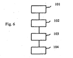
Figure 6 is a flowchart depicting a method of determining a reference torque to be applied on a steering control member. - As illustrated in
Figure 1 , the steer-by-wire steering system comprises acontrol member 2, which, in the case illustrated, is a steering wheel. Thecontrol member 2 could be a joystick, a lever or a rocker. It is through this member that a driver sets the reference path to be given to the vehicle. - The control angle α that the driver applies to the
control member 2 is measured by asensor 3, the signal from which is sent to aCPU 4. TheCPU 4 can suitably include a microprocessor, a data memory such as a RAM memory and a program memory such as a ROM memory. - The
CPU 4 may also receive a signal representative of the vehicle speed from aspeed sensor 5. - Using a preloaded computing routine, which takes into account the angle α of the control member and, possibly, the speed of the vehicle, the
CPU 4 generates an output signal that is sent to anactuator 6 responsible for the steering angle θ of the normally two or more steer wheels 7 (only a single steer wheel is shown inFigure 1 ) relative to the longitudinal axis of the vehicle. It is also conceivable to provide the steering system with two or several actuators, which each act on one steer wheel each. - As has just been described, a stream of signals goes from the
control member 2 to thesteer wheels 7, and in return thecontrol member 2 is subjected to a torque. To exert this torque, according to the invention, thecontrol member 2 is connected to anelastic element 12 such as a spring and to a torque generator 9. The torque generator 9 may, for example, be a DC motor connected to a resistor, the value of which may be adjusted by theCPU 4. The torque generator 9 is shown schematically by arotor 10, which is fastened to a shaft driven by thecontrol member 2, and by a stator 11. The torque generator 9 is connected to theCPU 4. - It may also be seen that the torque which is applied to the control member is delivered by an
elastic element 12, whose behaviour is therefore dictated by its elasticity coefficient, and a torque generator 9, whose behaviour can be parameterized. InFigure 1 , theelastic element 12 is shown by a spring. In other embodiments of the invention, theelastic element 12 may, for example, be a steel spring or a spring made of a composite material. It may also comprise a block of elastic composite material linked to the rotation shaft of thecontrol member 2. - It may also be pointed out that the steering system may be equipped with a
torque sensor 14 which measures the torque applied to thecontrol member 2. The signal transmitted by thesensor 14, representative of the torque applied to the control member, can be sent to theCPU 4. The function of thetorque sensor 14 will appear later. - According to the invention, the
control member 2 is subjected to a combined torque, delivered by theelastic element 12 and by the torque generator 9. - As this appears on
figure 5 , the invention provides for a method in which a reference torque has to be applied on thecontrol member 2. In afirst step 100, this reference torque can either have a predetermined value or be a function of the force exerted by awheel 7 on the steering actuator. - From this reference step, the
CPU 4 determines 200 a difference with the torque delivered by theelastic element 12. - The
CPU 4issues 300 an output signal towards the torque generator 9 which has the effect of adding to or subtracting from a torque to the torque produced by theelastic element 12. - In practice, essentially two types of torque that the torque generating means have to exert on the
control member 2 may be distinguished. - In one case, this is a static force that corresponds to the situation in which the driver applies a steady steering angle. This situation is illustrated in
Figure 3 . - Plotted on the y-axis in
Figure 2 is the torque applied to thecontrol member 2, which, in the example shown, varies between -10 and + 10 N.m against the angle α of the control member which, in the example shown varies between -600° and +600°. - In this case, it is necessary for the resistive torque generating means to exert an action on the
control member 2 for the purpose of bringing it back to its mid-point, that is to say a position in which the steer wheels are oriented along the longitudinal direction of the vehicle. In this situation, which may be termed the static situation, it may be desirable, for an angle of thecontrol member 2 of between approximately -600° and +600° about the mid-point, for the torque to have a substantially linear portion over a certain range about the mid-point, for example from -200° to +200° (for a small angle of the steering wheel, the resistive torque is low) about the mid-point, whereas, for angle values of less than -200° and greater than +200°, the torque may be constant and equal to the maximum value of the torque. Thecurve 31 showing the reference resistive torque is shown by the double lines. - The
elastic element 12 has a resistive torque that varies in a completely known manner according to its coefficient of elasticity. The resistive torque of theelastic element 12 is shown by the continuoussolid line 32. As this can be seen InFigure 3 , when thecontrol member 2 is at its mid point, theelastic element 12 is at its neutral position, i.e. for an angle of 0° of thecontrol member 2, theelastic element 12 exert on action of 0 N.m over thecontrol member 2. - As clearly shown in
Figure 2 , the torque generator 9 is used to deliver a torque that is added to or subtracted from the resistive torque delivered by theelastic element 12 in order to obtain the desired reference torque. It will be seen later how the reference value of the resistive torque is determined. - Furthermore, in the dynamic range, which corresponds to the situation in which a driver exerts an action on the
steering wheel 2 in order to steer the wheels,Figure 3 shows this situation.Figure 3 shows an action on thecontrol member 2 by a driver as a function of time; for example,Figure 3 illustrates the situation in which a control angle α of about 270° is demanded in 0.5 s. It is necessary for the action that the driver exerts on the steering wheel to be counteracted so that the driver communicates to the steering wheel a control signal that is compatible with the response time of the actuator or actuators which control the orientation of the driven wheels relative to the vehicle. Moreover, it may be a risk as regards the stability of the vehicle, especially at high speed, if the driver has the possibility of giving the control member 2 a high-amplitude impulse. -
Figure 4 shows the response of the resistive means as a function of time; plotted on the y-axis ofFigure 4 is the torque in N.m as a function of time. The reference torque is shown by thecurve 51. The resistive torque exerted by theelastic element 12 is shown by the continuous single line 62, while the resistive torque exerted by the torque generator 9 is shown by the broken line 63. It may be seen that the combined action of theelastic element 12 and the torque generator 9 makes it possible to approximate the theoretical reference resistive torque. - The combined operation of the
elastic element 12 and the torque generator 9 is similar in the unsteering case, that is to say in the case when the steering wheel is brought back to its mid-point from a steered position. - As regards the determination of the reference resistive torque, it may be envisaged to set the torque value relative to predetermined values that depend on the control angle α and on the speed of the vehicle. These reference torque values may, for example, be stored in a memory of the
CPU 4. In this situation, in which the reference resistive torque and the torque of theelastic element 12 are known for a given angle and a given speed, it is possible to determine the resistive torque that the torque generator 9 must exert. - It may also be envisaged to define the reference torque to be applied to the
control member 2 as a function of the force deployed by the turningactuator 7 for orienting the steer wheels.Figure 6 illustrates this possible method of defining the reference torque. In afirst step 101, thetorque sensor 14 is provided for this purpose; thesensor 14 measures the resistive torque exerted by theelastic element 12 and the torque generator 9. - In a
second step 102, the torque on the control member is compared to the or to a function of the torque exerted by awheel 7 on thesteering actuator 6, the difference is used to generate a signal that is sent, in athird step 103, to the torque generator 9 so that the latter adds torque to the resistive torque delivered by theelastic element 12 or subtracts this therefrom, depending on the case. This method of determining the reference torque provides a steering feeling which is closer to the steering feeling of a conventional mechanical steering system. - Of course, the invention is not restricted to the embodiment that has just been described by way of non-limiting example, but on the contrary it encompasses all embodiments thereof. The numerical values are, of course, purely indicative and are given merely as examples in order to make the invention easier to understand. In no way do they restrict the invention.
Claims (10)
- Steer-by-wire steering system for a motor vehicle, comprising:- a control member (2) allowing a user to give a set direction to the vehicle, the position α of which is identified by at least one sensor (3);- at least one steering actuator (6) that can orient at least one steer wheel (7) relative to the vehicle by an angle θ;- a processing means (4) that can receive an input signal representing the position of the control member coming from the at least one sensor (3) and that can transmit an output signal representing the angle θ to each of the steering actuators (6);- a means for generating a torque on the control member (2) having:characterized in that the torque generator (9) is capable of generating a torque that is added to or subtracted from the resistive torque generated by the elastic element (12) to obtain a reference torque defined for a given vehicle speed and a given control member angle.(i) an elastic element (12) that can generate, according to a known elasticity law, a resistive torque in reaction to an action exerted on the control member (2); and(ii) a torque generator (9);
- Steer-by-wire steering system according to claim 1, characterized in that it comprises a torque sensor (14) that can measure the torque actually applied to the control member (2).
- Steer-by-wire steering system according to Claim 1 or Claim 2, characterized in that the elastic element (12) obeys a linear elasticity law.
- Steer-by-wire steering system according to Claim 1 or Claim 2, characterized in that the elastic element (12) obeys a non-linear elasticity law.
- Steer-by-wire steering system according to one of Claims 1 to 4, characterized in that the elastic element (12) is a spring.
- Steer-by-wire steering system according to Claims 1 to 5, characterized in that the torque generator (9) is an electric motor.
- Method of determining a torque to be applied to a control member (2) for a given control position of said control member of a steer-by-wire steering system, characterized in that it comprises the steps of:- i. defining (100) a reference torque to be applied to the control member (2);- ii. determining (200) a difference between the reference torque and a resistive torque delivered by an elastic element (12) for the given position of the control member, and converting this difference into a signal; and- iii. delivering (300) this signal to a torque generator (9) in order to deliver a torque that is added to or subtracted from the resistive torque of the elastic element (12) in order to produce the reference torque.
- Method according to Claim 7, characterized in that the reference torque to be applied to the control member (2) is predetermined as a function of the control angle and the speed of the vehicle.
- Method according to Claim 7, characterized in that the reference torque to be applied to the control member (2) is a function of the force exerted by a wheel (7) on a steering actuator (6).
- Method according to Claim 9, characterized in that it comprises the steps of:- measuring (101) the torque applied to the control member (2);- comparing (102) the measured torque with the torque or a function of the torque exerted by a wheel (6) on a steering actuator (7) and converting the difference into a signal; and- transmitting (103) this signal to the torque generator (9) in order to deliver a torque that is added to or subtracted to the resistive torque from the elastic element (12) in order to produce the reference torque.
Applications Claiming Priority (1)
| Application Number | Priority Date | Filing Date | Title |
|---|---|---|---|
| PCT/IB2005/003110 WO2007017711A1 (en) | 2005-08-09 | 2005-08-09 | Steer-by-wire steering system and method of controlling the same |
Publications (2)
| Publication Number | Publication Date |
|---|---|
| EP1924482A1 EP1924482A1 (en) | 2008-05-28 |
| EP1924482B1 true EP1924482B1 (en) | 2009-11-04 |
Family
ID=36001126
Family Applications (1)
| Application Number | Title | Priority Date | Filing Date |
|---|---|---|---|
| EP05789456A Expired - Lifetime EP1924482B1 (en) | 2005-08-09 | 2005-08-09 | Steer-by-wire steering system and method of controlling the same |
Country Status (4)
| Country | Link |
|---|---|
| EP (1) | EP1924482B1 (en) |
| AT (1) | ATE447516T1 (en) |
| DE (1) | DE602005017521D1 (en) |
| WO (1) | WO2007017711A1 (en) |
Family Cites Families (5)
| Publication number | Priority date | Publication date | Assignee | Title |
|---|---|---|---|---|
| FR2678884B1 (en) * | 1991-07-12 | 1996-08-14 | Sextant Avionique | ROTARY ACTUATOR CAPABLE OF GENERATING ON THE HANDWHEEL OF A CONTROL SYSTEM, A VARIABLE RESISTANT TORQUE ACCORDING TO ADAPTIVE LAW. |
| JPH10203393A (en) * | 1997-01-21 | 1998-08-04 | Koyo Seiko Co Ltd | Vehicle steering system |
| US6557662B1 (en) * | 2000-11-22 | 2003-05-06 | Visteon Global Technologies, Inc. | Magneto-rheological simulated steering feel system |
| US6799654B2 (en) * | 2002-02-05 | 2004-10-05 | Delphi Technologies, Inc. | Hand wheel actuator |
| US6938720B2 (en) * | 2002-05-09 | 2005-09-06 | Delphi Technologies, Inc. | Steering input devices for steer-by-wire systems |
-
2005
- 2005-08-09 DE DE602005017521T patent/DE602005017521D1/en not_active Expired - Lifetime
- 2005-08-09 AT AT05789456T patent/ATE447516T1/en not_active IP Right Cessation
- 2005-08-09 WO PCT/IB2005/003110 patent/WO2007017711A1/en not_active Ceased
- 2005-08-09 EP EP05789456A patent/EP1924482B1/en not_active Expired - Lifetime
Also Published As
| Publication number | Publication date |
|---|---|
| ATE447516T1 (en) | 2009-11-15 |
| DE602005017521D1 (en) | 2009-12-17 |
| WO2007017711A1 (en) | 2007-02-15 |
| EP1924482A1 (en) | 2008-05-28 |
Similar Documents
| Publication | Publication Date | Title |
|---|---|---|
| CN111661149B (en) | Method for operating a steering system and steering system | |
| US6799654B2 (en) | Hand wheel actuator | |
| US7908056B2 (en) | Steer-by-wire system for automobiles | |
| US6154696A (en) | Steering control system for controlling torque steer | |
| US6095277A (en) | Vehicle steering system | |
| US5931256A (en) | Device for controlling a reaction force using an electric motor to provide a steering assistance force in a hydraulic power steering system | |
| EP2448806B1 (en) | A method and a system for assisting a driver of a vehicle during operation | |
| US7036626B2 (en) | Vehicle steering system for controlling a steering or steering lock angle of at least one wheel of a vehicle | |
| US6938720B2 (en) | Steering input devices for steer-by-wire systems | |
| EP1905670A2 (en) | Electric power steering apparatus | |
| US12509137B2 (en) | Steer-by-wire steering system with acceleration dependent steering torque feedback | |
| US12397854B2 (en) | Steering apparatus | |
| Baxter | Analysis of stiffness and feel for a power-assisted rack and pinion steering gear | |
| US12497095B2 (en) | Steering apparatus | |
| EP2585358B1 (en) | Method for electromechanically setting a steering angle and motor vehicle comprising an electromechanical steering system | |
| US20070235240A1 (en) | Power Steering | |
| EP1375299A1 (en) | Vehicle steering system, steer feel control system and method for providing steer feel | |
| US20110272204A1 (en) | Hydraulic Power-Assisted Steering and Method for Determining Steering Wheel Torque | |
| JP2000510627A (en) | Motor vehicle having at least one part controllable via at least one operating lever | |
| EP1710652A1 (en) | Bilatral servo controller | |
| EP1924482A1 (en) | Steer-by-wire steering system and method of controlling the same | |
| JP4434261B2 (en) | Steering device | |
| US7677352B2 (en) | Method for steering a vehicle by means of a superimposed steering system | |
| US12319371B2 (en) | Method for determining a steering damping requirement, steering system, computer program product and storage medium | |
| US20260035034A1 (en) | Method for Operating a Steering System |
Legal Events
| Date | Code | Title | Description |
|---|---|---|---|
| PUAI | Public reference made under article 153(3) epc to a published international application that has entered the european phase |
Free format text: ORIGINAL CODE: 0009012 |
|
| 17P | Request for examination filed |
Effective date: 20080310 |
|
| AK | Designated contracting states |
Kind code of ref document: A1 Designated state(s): AT BE BG CH CY CZ DE DK EE ES FI FR GB GR HU IE IS IT LI LT LU LV MC NL PL PT RO SE SI SK TR |
|
| 17Q | First examination report despatched |
Effective date: 20080718 |
|
| GRAP | Despatch of communication of intention to grant a patent |
Free format text: ORIGINAL CODE: EPIDOSNIGR1 |
|
| GRAS | Grant fee paid |
Free format text: ORIGINAL CODE: EPIDOSNIGR3 |
|
| DAX | Request for extension of the european patent (deleted) | ||
| GRAA | (expected) grant |
Free format text: ORIGINAL CODE: 0009210 |
|
| AK | Designated contracting states |
Kind code of ref document: B1 Designated state(s): AT BE BG CH CY CZ DE DK EE ES FI FR GB GR HU IE IS IT LI LT LU LV MC NL PL PT RO SE SI SK TR |
|
| REG | Reference to a national code |
Ref country code: GB Ref legal event code: FG4D |
|
| REG | Reference to a national code |
Ref country code: CH Ref legal event code: EP |
|
| REG | Reference to a national code |
Ref country code: IE Ref legal event code: FG4D |
|
| REF | Corresponds to: |
Ref document number: 602005017521 Country of ref document: DE Date of ref document: 20091217 Kind code of ref document: P |
|
| REG | Reference to a national code |
Ref country code: SE Ref legal event code: TRGR |
|
| LTIE | Lt: invalidation of european patent or patent extension |
Effective date: 20091104 |
|
| PG25 | Lapsed in a contracting state [announced via postgrant information from national office to epo] |
Ref country code: PT Free format text: LAPSE BECAUSE OF FAILURE TO SUBMIT A TRANSLATION OF THE DESCRIPTION OR TO PAY THE FEE WITHIN THE PRESCRIBED TIME-LIMIT Effective date: 20100304 Ref country code: LT Free format text: LAPSE BECAUSE OF FAILURE TO SUBMIT A TRANSLATION OF THE DESCRIPTION OR TO PAY THE FEE WITHIN THE PRESCRIBED TIME-LIMIT Effective date: 20091104 Ref country code: FI Free format text: LAPSE BECAUSE OF FAILURE TO SUBMIT A TRANSLATION OF THE DESCRIPTION OR TO PAY THE FEE WITHIN THE PRESCRIBED TIME-LIMIT Effective date: 20091104 Ref country code: ES Free format text: LAPSE BECAUSE OF FAILURE TO SUBMIT A TRANSLATION OF THE DESCRIPTION OR TO PAY THE FEE WITHIN THE PRESCRIBED TIME-LIMIT Effective date: 20100215 Ref country code: IS Free format text: LAPSE BECAUSE OF FAILURE TO SUBMIT A TRANSLATION OF THE DESCRIPTION OR TO PAY THE FEE WITHIN THE PRESCRIBED TIME-LIMIT Effective date: 20100304 |
|
| PG25 | Lapsed in a contracting state [announced via postgrant information from national office to epo] |
Ref country code: SI Free format text: LAPSE BECAUSE OF FAILURE TO SUBMIT A TRANSLATION OF THE DESCRIPTION OR TO PAY THE FEE WITHIN THE PRESCRIBED TIME-LIMIT Effective date: 20091104 Ref country code: CY Free format text: LAPSE BECAUSE OF FAILURE TO SUBMIT A TRANSLATION OF THE DESCRIPTION OR TO PAY THE FEE WITHIN THE PRESCRIBED TIME-LIMIT Effective date: 20091104 Ref country code: LV Free format text: LAPSE BECAUSE OF FAILURE TO SUBMIT A TRANSLATION OF THE DESCRIPTION OR TO PAY THE FEE WITHIN THE PRESCRIBED TIME-LIMIT Effective date: 20091104 Ref country code: PL Free format text: LAPSE BECAUSE OF FAILURE TO SUBMIT A TRANSLATION OF THE DESCRIPTION OR TO PAY THE FEE WITHIN THE PRESCRIBED TIME-LIMIT Effective date: 20091104 |
|
| PG25 | Lapsed in a contracting state [announced via postgrant information from national office to epo] |
Ref country code: AT Free format text: LAPSE BECAUSE OF FAILURE TO SUBMIT A TRANSLATION OF THE DESCRIPTION OR TO PAY THE FEE WITHIN THE PRESCRIBED TIME-LIMIT Effective date: 20091104 Ref country code: BE Free format text: LAPSE BECAUSE OF FAILURE TO SUBMIT A TRANSLATION OF THE DESCRIPTION OR TO PAY THE FEE WITHIN THE PRESCRIBED TIME-LIMIT Effective date: 20091104 |
|
| PG25 | Lapsed in a contracting state [announced via postgrant information from national office to epo] |
Ref country code: DK Free format text: LAPSE BECAUSE OF FAILURE TO SUBMIT A TRANSLATION OF THE DESCRIPTION OR TO PAY THE FEE WITHIN THE PRESCRIBED TIME-LIMIT Effective date: 20091104 Ref country code: BG Free format text: LAPSE BECAUSE OF FAILURE TO SUBMIT A TRANSLATION OF THE DESCRIPTION OR TO PAY THE FEE WITHIN THE PRESCRIBED TIME-LIMIT Effective date: 20100204 Ref country code: EE Free format text: LAPSE BECAUSE OF FAILURE TO SUBMIT A TRANSLATION OF THE DESCRIPTION OR TO PAY THE FEE WITHIN THE PRESCRIBED TIME-LIMIT Effective date: 20091104 Ref country code: RO Free format text: LAPSE BECAUSE OF FAILURE TO SUBMIT A TRANSLATION OF THE DESCRIPTION OR TO PAY THE FEE WITHIN THE PRESCRIBED TIME-LIMIT Effective date: 20091104 |
|
| PG25 | Lapsed in a contracting state [announced via postgrant information from national office to epo] |
Ref country code: SK Free format text: LAPSE BECAUSE OF FAILURE TO SUBMIT A TRANSLATION OF THE DESCRIPTION OR TO PAY THE FEE WITHIN THE PRESCRIBED TIME-LIMIT Effective date: 20091104 Ref country code: CZ Free format text: LAPSE BECAUSE OF FAILURE TO SUBMIT A TRANSLATION OF THE DESCRIPTION OR TO PAY THE FEE WITHIN THE PRESCRIBED TIME-LIMIT Effective date: 20091104 |
|
| PLBE | No opposition filed within time limit |
Free format text: ORIGINAL CODE: 0009261 |
|
| STAA | Information on the status of an ep patent application or granted ep patent |
Free format text: STATUS: NO OPPOSITION FILED WITHIN TIME LIMIT |
|
| 26N | No opposition filed |
Effective date: 20100805 |
|
| PG25 | Lapsed in a contracting state [announced via postgrant information from national office to epo] |
Ref country code: GR Free format text: LAPSE BECAUSE OF FAILURE TO SUBMIT A TRANSLATION OF THE DESCRIPTION OR TO PAY THE FEE WITHIN THE PRESCRIBED TIME-LIMIT Effective date: 20100205 |
|
| PG25 | Lapsed in a contracting state [announced via postgrant information from national office to epo] |
Ref country code: MC Free format text: LAPSE BECAUSE OF NON-PAYMENT OF DUE FEES Effective date: 20100831 |
|
| REG | Reference to a national code |
Ref country code: CH Ref legal event code: PL |
|
| PG25 | Lapsed in a contracting state [announced via postgrant information from national office to epo] |
Ref country code: CH Free format text: LAPSE BECAUSE OF NON-PAYMENT OF DUE FEES Effective date: 20100831 Ref country code: LI Free format text: LAPSE BECAUSE OF NON-PAYMENT OF DUE FEES Effective date: 20100831 |
|
| PG25 | Lapsed in a contracting state [announced via postgrant information from national office to epo] |
Ref country code: IE Free format text: LAPSE BECAUSE OF NON-PAYMENT OF DUE FEES Effective date: 20100809 |
|
| PG25 | Lapsed in a contracting state [announced via postgrant information from national office to epo] |
Ref country code: HU Free format text: LAPSE BECAUSE OF FAILURE TO SUBMIT A TRANSLATION OF THE DESCRIPTION OR TO PAY THE FEE WITHIN THE PRESCRIBED TIME-LIMIT Effective date: 20100505 Ref country code: LU Free format text: LAPSE BECAUSE OF NON-PAYMENT OF DUE FEES Effective date: 20100809 |
|
| PG25 | Lapsed in a contracting state [announced via postgrant information from national office to epo] |
Ref country code: TR Free format text: LAPSE BECAUSE OF FAILURE TO SUBMIT A TRANSLATION OF THE DESCRIPTION OR TO PAY THE FEE WITHIN THE PRESCRIBED TIME-LIMIT Effective date: 20091104 |
|
| PGFP | Annual fee paid to national office [announced via postgrant information from national office to epo] |
Ref country code: DE Payment date: 20140806 Year of fee payment: 10 Ref country code: NL Payment date: 20140809 Year of fee payment: 10 |
|
| PGFP | Annual fee paid to national office [announced via postgrant information from national office to epo] |
Ref country code: FR Payment date: 20140808 Year of fee payment: 10 Ref country code: GB Payment date: 20140806 Year of fee payment: 10 Ref country code: SE Payment date: 20140826 Year of fee payment: 10 |
|
| REG | Reference to a national code |
Ref country code: DE Ref legal event code: R082 Ref document number: 602005017521 Country of ref document: DE Representative=s name: V. FUENER EBBINGHAUS FINCK HANO, DE |
|
| PGFP | Annual fee paid to national office [announced via postgrant information from national office to epo] |
Ref country code: IT Payment date: 20140818 Year of fee payment: 10 |
|
| REG | Reference to a national code |
Ref country code: GB Ref legal event code: 732E Free format text: REGISTERED BETWEEN 20141229 AND 20141231 |
|
| REG | Reference to a national code |
Ref country code: DE Ref legal event code: R082 Ref document number: 602005017521 Country of ref document: DE Representative=s name: V. FUENER EBBINGHAUS FINCK HANO, DE Effective date: 20141219 Ref country code: DE Ref legal event code: R081 Ref document number: 602005017521 Country of ref document: DE Owner name: VOLVO TRUCK CORP., SE Free format text: FORMER OWNER: RENAULT TRUCKS, SAINT PRIEST, FR Effective date: 20141219 |
|
| REG | Reference to a national code |
Ref country code: FR Ref legal event code: TP Owner name: VOLVO LASTVAGNAR AKTIEBOLAG, SE Effective date: 20150209 |
|
| REG | Reference to a national code |
Ref country code: NL Ref legal event code: SD Effective date: 20150703 |
|
| REG | Reference to a national code |
Ref country code: DE Ref legal event code: R119 Ref document number: 602005017521 Country of ref document: DE |
|
| REG | Reference to a national code |
Ref country code: SE Ref legal event code: EUG |
|
| GBPC | Gb: european patent ceased through non-payment of renewal fee |
Effective date: 20150809 |
|
| PG25 | Lapsed in a contracting state [announced via postgrant information from national office to epo] |
Ref country code: IT Free format text: LAPSE BECAUSE OF NON-PAYMENT OF DUE FEES Effective date: 20150809 |
|
| REG | Reference to a national code |
Ref country code: NL Ref legal event code: MM Effective date: 20150901 |
|
| PG25 | Lapsed in a contracting state [announced via postgrant information from national office to epo] |
Ref country code: SE Free format text: LAPSE BECAUSE OF NON-PAYMENT OF DUE FEES Effective date: 20150810 |
|
| REG | Reference to a national code |
Ref country code: FR Ref legal event code: ST Effective date: 20160429 |
|
| PG25 | Lapsed in a contracting state [announced via postgrant information from national office to epo] |
Ref country code: NL Free format text: LAPSE BECAUSE OF NON-PAYMENT OF DUE FEES Effective date: 20150901 |
|
| PG25 | Lapsed in a contracting state [announced via postgrant information from national office to epo] |
Ref country code: GB Free format text: LAPSE BECAUSE OF NON-PAYMENT OF DUE FEES Effective date: 20150809 Ref country code: DE Free format text: LAPSE BECAUSE OF NON-PAYMENT OF DUE FEES Effective date: 20160301 |
|
| PG25 | Lapsed in a contracting state [announced via postgrant information from national office to epo] |
Ref country code: FR Free format text: LAPSE BECAUSE OF NON-PAYMENT OF DUE FEES Effective date: 20150831 |