EP1923866A1 - Sound source separating device, speech recognizing device, portable telephone, and sound source separating method, and program - Google Patents
Sound source separating device, speech recognizing device, portable telephone, and sound source separating method, and program Download PDFInfo
- Publication number
- EP1923866A1 EP1923866A1 EP06782692A EP06782692A EP1923866A1 EP 1923866 A1 EP1923866 A1 EP 1923866A1 EP 06782692 A EP06782692 A EP 06782692A EP 06782692 A EP06782692 A EP 06782692A EP 1923866 A1 EP1923866 A1 EP 1923866A1
- Authority
- EP
- European Patent Office
- Prior art keywords
- sound source
- sound
- microphones
- processing
- speech
- Prior art date
- Legal status (The legal status is an assumption and is not a legal conclusion. Google has not performed a legal analysis and makes no representation as to the accuracy of the status listed.)
- Granted
Links
Images
















Classifications
-
- G—PHYSICS
- G10—MUSICAL INSTRUMENTS; ACOUSTICS
- G10L—SPEECH ANALYSIS TECHNIQUES OR SPEECH SYNTHESIS; SPEECH RECOGNITION; SPEECH OR VOICE PROCESSING TECHNIQUES; SPEECH OR AUDIO CODING OR DECODING
- G10L15/00—Speech recognition
- G10L15/20—Speech recognition techniques specially adapted for robustness in adverse environments, e.g. in noise, of stress induced speech
-
- G—PHYSICS
- G10—MUSICAL INSTRUMENTS; ACOUSTICS
- G10L—SPEECH ANALYSIS TECHNIQUES OR SPEECH SYNTHESIS; SPEECH RECOGNITION; SPEECH OR VOICE PROCESSING TECHNIQUES; SPEECH OR AUDIO CODING OR DECODING
- G10L21/00—Speech or voice signal processing techniques to produce another audible or non-audible signal, e.g. visual or tactile, in order to modify its quality or its intelligibility
- G10L21/02—Speech enhancement, e.g. noise reduction or echo cancellation
- G10L21/0272—Voice signal separating
-
- H—ELECTRICITY
- H04—ELECTRIC COMMUNICATION TECHNIQUE
- H04R—LOUDSPEAKERS, MICROPHONES, GRAMOPHONE PICK-UPS OR LIKE ACOUSTIC ELECTROMECHANICAL TRANSDUCERS; ELECTRIC HEARING AIDS; PUBLIC ADDRESS SYSTEMS
- H04R1/00—Details of transducers, loudspeakers or microphones
- H04R1/20—Arrangements for obtaining desired frequency or directional characteristics
- H04R1/32—Arrangements for obtaining desired frequency or directional characteristics for obtaining desired directional characteristic only
- H04R1/40—Arrangements for obtaining desired frequency or directional characteristics for obtaining desired directional characteristic only by combining a number of identical transducers
- H04R1/406—Arrangements for obtaining desired frequency or directional characteristics for obtaining desired directional characteristic only by combining a number of identical transducers microphones
-
- G—PHYSICS
- G10—MUSICAL INSTRUMENTS; ACOUSTICS
- G10L—SPEECH ANALYSIS TECHNIQUES OR SPEECH SYNTHESIS; SPEECH RECOGNITION; SPEECH OR VOICE PROCESSING TECHNIQUES; SPEECH OR AUDIO CODING OR DECODING
- G10L21/00—Speech or voice signal processing techniques to produce another audible or non-audible signal, e.g. visual or tactile, in order to modify its quality or its intelligibility
- G10L21/02—Speech enhancement, e.g. noise reduction or echo cancellation
- G10L21/0208—Noise filtering
- G10L21/0216—Noise filtering characterised by the method used for estimating noise
- G10L2021/02161—Number of inputs available containing the signal or the noise to be suppressed
- G10L2021/02166—Microphone arrays; Beamforming
-
- H—ELECTRICITY
- H04—ELECTRIC COMMUNICATION TECHNIQUE
- H04R—LOUDSPEAKERS, MICROPHONES, GRAMOPHONE PICK-UPS OR LIKE ACOUSTIC ELECTROMECHANICAL TRANSDUCERS; ELECTRIC HEARING AIDS; PUBLIC ADDRESS SYSTEMS
- H04R2430/00—Signal processing covered by H04R, not provided for in its groups
- H04R2430/20—Processing of the output signals of the acoustic transducers of an array for obtaining a desired directivity characteristic
-
- H—ELECTRICITY
- H04—ELECTRIC COMMUNICATION TECHNIQUE
- H04R—LOUDSPEAKERS, MICROPHONES, GRAMOPHONE PICK-UPS OR LIKE ACOUSTIC ELECTROMECHANICAL TRANSDUCERS; ELECTRIC HEARING AIDS; PUBLIC ADDRESS SYSTEMS
- H04R2499/00—Aspects covered by H04R or H04S not otherwise provided for in their subgroups
- H04R2499/10—General applications
- H04R2499/11—Transducers incorporated or for use in hand-held devices, e.g. mobile phones, PDA's, camera's
-
- H—ELECTRICITY
- H04—ELECTRIC COMMUNICATION TECHNIQUE
- H04R—LOUDSPEAKERS, MICROPHONES, GRAMOPHONE PICK-UPS OR LIKE ACOUSTIC ELECTROMECHANICAL TRANSDUCERS; ELECTRIC HEARING AIDS; PUBLIC ADDRESS SYSTEMS
- H04R2499/00—Aspects covered by H04R or H04S not otherwise provided for in their subgroups
- H04R2499/10—General applications
- H04R2499/13—Acoustic transducers and sound field adaptation in vehicles
Definitions
- the present invention relates to a sound source separation device, a speech recognition device, a mobile telephone, a sound source separation method, and a program which uses a plurality of microphones and separates a sound source signal of a target sound source from a signal which consists of a plurality of acoustic signals emitted from a plurality of sound sources such as a plurality of speech signals and various background noises.
- the current speech recognition technology has a problem of degradation of recognition performance when a plurality of speakers speaks simultaneously. Since the current speech recognition technology does not provide high speech recognition accuracy for a mixed simultaneous speech of two speakers, a passenger other than a speaker is not allowed to speak during the speech recognition device is used. Under this situation, behavior of the passenger is restricted. Although a principal independent component analysis method or the like have applied to separate such sound sources, it is not practical enough because of computational complexity, variations of the number of sound sources, and the like.
- these uneven characteristic In processing of an addition type array such as a delay-and-sum array in microphone array technologies, these uneven characteristic only prevents microphone array performance to be achieved as designed. However, in a so-called subtraction type array such as an adaptive array, these uneven characteristic may degrade performance especially in low frequencies less than or equal to about 1 kHz compared to a case where one microphone is used.
- the adaptive beamforming processing is basically a processing to suppress noise by a filter which forms a directional beam having a directional null (blind spot) in a direction of a noise source, and a generalized sidelobe canceller is known to have relatively high performance especially among them.
- the GSC has a problem that a target signal is suppressed and degraded when the target signal is arrived from a direction different from a direction of a specified target sound source.
- Patent Documents 6 and 7 discloses a method which performs processing in a frequency domain so that a computational complexity is reduced, and a direction of a speaker and a direction of a specific noise are successively detected by using filter coefficients in the frequency domain, a target sound is separated from a noise other than the target sound to some extent, and spectral subtraction is applied as well, so that a noise from unknown arrival direction and a diffuse noise are reduced.
- Patent Document 1 JP5-131866A
- Patent Document 2 JP2002-99297A
- Patent Document 3 JP2003-153372A
- Patent Document 4 JP2004-343700A
- Patent Document 5 JP2004-289762A
- Patent Document 6 JP2001-100800A
- Patent Document 7 JP2000-47699A
- Non-Patent Document 1 The Institute of Electronics, Information and Communication Engineers, "Acoustic Systems and Digital Processing” [Non-Patent Document 2] HAykin, "ADAptive Filter Theory (Prentice HAll)"
- a reference signal which is a suppressed target sound
- a reference signal which is a suppressed target sound
- the target sound cannot be sufficiently suppressed and thus the target sound is contained in both the reference signal and a target signal in the adaptive filter section. Therefore the target sound is distorted and quality of the sound is degraded as a result of application of adaptive filter processing. Also in a closed space where an initial reflection is strong, a target sound signal is leaked into a reference signal so that the similar phenomenon occurs.
- an adaptive filter in general, if there is a high correlation between a reference signal and a target signal, estimation process of the adaptive filter cannot perform well and thereby estimation accuracy is significantly degraded. As an example, there is a case where a target sound and a noise are both speech signals. A similar problem occurs in an echo canceller, and in an adaptive filter which estimates an echo mixed from a far-end signal into a near-end signal, when two persons speak simultaneously at far and near ends, a so-called double-talk state occurs and thereby performance of the echo canceller is degraded. Therefore, it is an important condition to maintain the performance how precise a double-talk state is detected in order to stop parameter estimation of an adaptive filter or slow down the speed of the estimation.
- the present invention is made in view of the above described problems, and is intended to provide a sound source separation device, a speech recognition device, a mobile telephone, a sound source separation method, and a program which allow to separate a sound source signal of a target sound source from a mixed sound which includes sound source signals emitted from a plurality of sound sources without being affected by uneven sensitivity of microphone elements.
- an invention provides a sound source separation device for separating a sound source signal of a target sound source from a mixed sound which includes sound source signals emitted from a plurality of sound sources using at least two microphones arranged separately from each other comprising: beamforming means for performing a first beamforming processing to attenuate a sound source signal arriving from a predetermined direction by performing computations using first coefficients on an output signal of said microphones, and performing a second beamforming processing to attenuate a sound source signal arriving from a direction symmetrical to said predetermined direction with respect to a perpendicular line to a straight line connecting the two microphones by performing computations using second coefficients which are complex conjugate of said first coefficients in a frequency domain on the output signal of said microphones; power computation means for computing power spectrum information with respect to each of sound source signals obtained by said beamforming means; and target sound spectrum extraction means for extracting spectrum information of a target sound source based on a difference between the power spectrum information calculated by said power computation means
- the sound source separation device provides a directional characteristics which is not affected by sensitivities of microphone elements, and allows to separate a sound source signal of a target sound source from a mixed sound which includes sound source signals emitted from a plurality of sound sources without being affected by uneven sensitivity of the microphone elements.
- An invention according to claim 2 is the sound source separation device according to claim 1, wherein said beamforming means applies said first beamforming processing and said second beamforming processing to each of a combination of any two microphones among three microphones which arranged separately from each other and another combination of two microphones among said three microphones.
- a sound source signal from a target sound source which locates in each area whose boundary is a perpendicular line to a straight line connecting two microphones among three microphones.
- An invention according to claim 3 is the sound source separation device according to claim 1 or 2, further comprising directional characteristics control means for applying a delay to an output signal of a microphone. According to this invention, directional characteristics can be compensated to its optimum condition by applying a delay, and separation performance of sound sources can be improved.
- An invention according to claim 4 is the sound source separation device according to claim 3, wherein said directional characteristics control means virtually generates output signals of three microphones by applying a delay to an output signal of at least one microphone among two microphones. According to this invention, since output signals from three microphones can be virtually generated, a sound source signal arriving from a direction of a perpendicular line to a straight line connecting two microphones can be separated and extracted using only the two microphones.
- An invention according to claim 5 is the sound source separation device according to claim 3 or 4, further comprising arrival direction estimating means for estimating a arrival direction of said sound source signal, wherein said directional characteristics control means applies a delay to an output signal of the microphone such that two sound sources virtually locate symmetrically with respect to a perpendicular line to a straight line connecting the two microphones based on an arrival direction estimated by said arrival direction estimating means. According to this invention, delay operation can be performed such that high separation performance of sound sources is obtained.
- An invention according to claim 6 is the sound source separation device according to any one of claims 1 to 5, further comprising spectral subtraction means for performing spectral subtraction processing on the power spectrum information extracted by said target sound extraction means. According to this invention, a stationary noise whose arrival direction is unknown, a diffuse noise, and the like can be suppressed by performing the spectral subtraction processing.
- An invention according to claim 7 is the sound source separation device according to any one of claims 1 to 6, further comprising stationary noise reduction means for performing processing to reduce noise before the processing by said beamforming means is performed. According to this invention, generation of a perceptually unpleasant noise such as a musical noise can be reduced.
- An invention according to claim 8 provides a speech recognition device comprising speech recognition means for performing speech recognition of a sound source signal separated by the sound source separation device according to any one of claims 1 to 7.
- An invention according to claim 9 is the speech recognition device according to claim 8, further comprising recognition vocabulary list storage means for storing a driver's seat side recognition vocabulary list which is a list of candidates of vocabulary spoken from a driver's seat side of a vehicle and a passenger's seat side recognition vocabulary list which is a list of candidates of vocabulary spoken from a passenger's seat side, wherein said speech recognition means performs speech recognition processing of a sound source signal separated by said sound source separation device based on the driver's seat side recognition vocabulary list and the passenger's seat side recognition vocabulary list stored in said recognition vocabulary list storage means.
- the speech recognition device since the speech recognition device performs speech recognition processing based on the passenger's seat side recognition vocabulary list and the driver's seat side recognition vocabulary list stored in the recognition vocabulary list storage means, an optimal vocabulary item can be selected from a vocabulary list separately between a driver's seat side and a passenger's seat side so that accurate speech recognition can be performed.
- An invention according to claim 10 is the speech recognition device according to claim 8 or 9, further comprising: state transition means for managing a current state of a vehicle; valid vocabulary list storage means for storing a valid vocabulary list of the passenger's seat side and the driver's seat side depending on a state of the vehicle; and control means for determining whether a vocabulary item recognized by said speech recognition means is valid or not based on the current state of the vehicle managed by said state transition means and the vocabulary list stored in said valid vocabulary list storage means, and controlling depending on the determination result.
- control contributes to the comforts of persons in vehicle because validness of recognized vocabulary item can be determined based on a current state of a vehicle and a valid vocabulary list, and control can be performed depending on the determination result.
- a valid vocabulary list and contents of control can be designed freely so that flexibility can be given to application design using speech recognition.
- An invention according to claim 11 provides a mobile phone comprising the sound source separation device according to any one of claims 1 to 7.
- a mobile phone can be used as a sound collecting microphone in a medium sized conference room and the like.
- An invention according to claim 12 provides a sound source separation method comprising: a sound source signal receiving step of inputting sound source signals emitted from a plurality of sound sources to at least two microphones arranged separately from each other; a beamforming processing step of performing a first beamforming processing and a second beamforming processing to attenuate sound source signals arriving from predetermined directions symmetrical with respect to a perpendicular line to a straight line connecting two microphones respectively by performing computations using two weighted coefficients which are complex conjugate to each other in a frequency domain on an output signal of said microphone respectively; a power computation step of computing power spectrum information with respect to each of sound source signals obtained in said beamforming processing step; and a target sound spectrum extracting step of extracting spectrum information of a target sound source based on a difference between the power spectrum information calculated in said power computation step.
- An invention according to claim 13 provides a program for causing a computer to perform: an output signal acquisition step of acquiring an output signal which includes sound source signals emitted from a plurality of sound sources are mixed from at least two microphones arranged separately from each other; a beamforming processing step of performing a first beamforming processing and a second beamforming processing to attenuate sound source signals arriving from predetermined directions symmetrical with respect to a perpendicular line to a straight line connecting two microphones respectively by performing computations using two weighted coefficients which are complex conjugate to each other in a frequency domain on the output signal acquired in said output signal acquisition step respectively; a power computation step of computing power spectrum information with respect to each of sound source signals obtained in said beamforming processing step; and a target sound spectrum extracting step of extracting spectrum information of a target sound source based on a difference between the power spectrum information calculated in said power computation step.
- a first beamforming processing and a second beamforming processing are performed for attenuating sound source signals arriving from predetermined directions symmetrical with respect to a perpendicular line to a straight line connecting two microphones respectively by performing operations using two weighted coefficients which are complex conjugate to each other in a frequency domain, thereby the sound source signals arriving from the predetermined directions symmetrical with respect to the perpendicular line to the straight line connecting two the microphones respectively are attenuated, and spectrum information of a target sound source is extracted based on a difference between respective power spectrum information of sound source signals obtained by the first beamforming processing and the second beamforming processing.
- a directional characteristics which is not affected by sensitivity of microphone elements can be achieved, and a sound source signal from a target sound source can be separated from a mixed sound which contains sound source signals emitted from a plurality of sound sources without being affected by uneven sensitivity of the microphone elements.
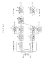
- FIG. 1 is a diagram which shows a basic configuration of a sound source separation system according to the first embodiment of the present invention.
- This system is comprised of two microphones (hereinafter referred to as MIC) 10, 11 and a sound source separation device 1.
- This sound source separation device 1 includes a CPU that performs overall control and arithmetic processing, hardware including storage devices a ROM, a RAM, and a hard disk device, and software including a program, data, and the like stored in the storage devices, which are not shown. Function blocks shown in Figure 1 are implemented by these hardware and software.
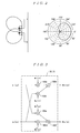
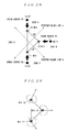
- the two MICs 10 and 11 are non-directional MICs and arranged separately by a few centimeters from each other on a plane. Although the MICs 10 and 11 are basically omnidirectional, unidirectional microphones may be used as shown in Figure 2 .
- the MICs 10 and 11 receive signals emitted from two sound sources R1 and R2. At this time, these two sound sources R1 and R2 locate in two areas divided by a perpendicular line to a straight line connecting the two MICs 10 and 11 as a boundary (hereinafter referred to as "left and right of a perpendicular line") respectively, but their location do not have to be symmetrical with respect to the perpendicular line.
- Frequency analysis is performed for each output of the MICs 10 and 11 which pick up two sound source signals by spectrum analysis sections 20 and 21.
- the frequency-analyzed sound source signals is filtered by beamformers 30 and 31 which form symmetrical directional nulls in the left and right of the perpendicular line to the straight line connecting the two MICs 10 and 11 in the beamformer section 3.
- Power of the filer output is computed by power computation sections 40 and 41.
- processing is performed by target sound spectrum extraction sections 50 and 51 such that respective differences are computed, and a computed result value is outputted if the value is grater than or equal to a certain value, and if not, the value is set to zero.
- These processings differs from common processing for forming a directional null for a specific noise, and configures the beamformer section 3 under some conditions and performs the above described processings, so that the conventional problem of degradation of characteristics of a microphone array due to uneven sensitivity of microphone elements can be solved, and a directional characteristic which separates sounds from left and right with respect to the perpendicular line as described above can be achieved for a broad frequency band.
- Each functional block will be described in detail below.
- signals x 1 ( ⁇ ) and x 2 ( ⁇ ) which are decomposed for each frequency component by spectrum analysis sections 20 and 21 are inputted, and are multiplied by weighted coefficients of filter w 1 ( ⁇ ), w 2 ( ⁇ ), w 1 *( ⁇ ), w 2 *( ⁇ ) (* indicates complex conjugate) respectively by multipliers 100a, 100b, 100c and 100d. And two multiplication results are added by adders 100e and 100f, and filtering processing results ds 1 ( ⁇ ), ds 2 ( ⁇ ) are outputted as outputs of them.
- the beamformer section 3 forms directional nulls in symmetrical positions with respect to a perpendicular line to a straight line connecting the MICs 10 and 11 by using complex conjugate filter coefficients.
- the power computation sections 40 and 41 convert outputs ds 1 ( ⁇ ) and ds 2 ( ⁇ ) from the beamformer 30 and the beamformer 31 to power spectrum information ps 1 ( ⁇ ) and ps 2 ( ⁇ ) by the following calculating equations.
- ps 1 ( ⁇ ) and ps 2 ( ⁇ ), which are outputs of the power computation sections 40 and 41, are used as two inputs to the target sound spectrum extraction sections 50 and 51.
- the target sound spectrum extraction sections 50 and 51 receive power spectrum information outputted from the two beamformers 30 and 31 as inputs, and output left and right target sounds as outputs respectively.
- the target sound spectrum extraction sections 50 and 51 are internally composed of difference calculation sections 500 and 510 and coefficient conversion sections 501 and 511.
- the difference calculation section 500 subtracts power spectrum information of the beamformer 31 from that of the beamformer 30 in the subtractor 500a, and similarly the difference calculation section 510 subtracts power spectrum information of the beamformer 30 from that of the beamformer 31 in the subtractor 501a, and their results are then inputted to the coefficient conversion sections 501 and 511 respectively.
- the coefficient conversion sections 501 and 511 are blocks for separating left and right sounds respectively.
- the coefficient conversion sections 501 and 511 output spectrum information that are values greater than or equal to certain threshold values as signals from target directions respectively. Although a threshold value is typically "0" as used herein, an optimum threshold value may be obtained by actual measurement and individually set depending on a use environment.
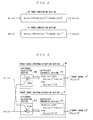
- the spectrum-analyzed two signals are filtered by the beamformers 30 and 31 in which directional nulls are formed symmetrically with respect to the perpendicular line to the straight line connecting the MICs 10 and 11, so that a signal from a specific direction is attenuated. However, in this case, it is not intended to precisely estimate an arrival direction of specific sound source and direct a directional null to the precisely estimated sound source direction.
- This filtering using inputs of two channels are performed for each frequency component, and outputs of the beamformers 30 and 31 are converted to spectrum power information by the power computation sections 40 and 41, at the same time phase information ⁇ 1 and ⁇ 2 are extracted from the outputs of the beamformers 30 and 31 by a phase extraction sections 60 and 61.
- the outputs of the beamformers 30 and 31 which have been converted to the spectrum power information by the power calculation sections 40 and 41 are sent to the target sound spectrum extraction sections 50 and 51.
- power spectrum information of a sound source signal coming from right direction (0 degree to 90 degrees) is extracted by the target sound spectrum extraction section 50
- power spectrum information of a sound source signal coming from left direction is extracted by the target sound spectrum extraction section 51.
- the relevant power spectrum information is sent to an acoustic parameter analysis section (not shown) in which acoustic analysis processing is performed on the power spectrum information.
- the phase information extracted by the phase extraction sections 60 and 61 and the spectrum information extracted by the target sound spectrum extraction sections 50 and 51 are inputted to a time waveform conversion sections 70 and 71 to be converted back to time signal information.
- weight vector W and directional vector V are defined by the following expressions.
- dr 1 ( ⁇ ) which is an output of the difference operation section 500 in the target sound spectrum extraction section 50 can be obtained as follows.
- ⁇ is introduced as a parameter representing an uneven sensitivity of MIC elements, and a sensitivity of one MIC element is assumed to be ⁇ , times of that of the other MIC element.
- a directional characteristic is not changed even if a sensitivity of microphone element is changed. Then, if a sound source is sufficiently away from a MIC, i.e., in case of a plane wave, the direction vector is expressed as:
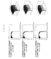
- Figure 8 is an example of a directional characteristic of a difference result in a design in which, when a directional null is formed in direction of ⁇ 45 degrees from the perpendicular line as described above, constrains for maintaining gains of the beamformers 30 and 31 are specified in symmetrical positions ( ⁇ 45 degrees) with respect to the perpendicular line.
- a directional characteristics of a single beamformer is shown in Figure 10 in which a difference of sensitivity of MIC elements ⁇ is varied to 0 db, +6 db, and -6 db, and it can be seen from this figure that, if the sensitivity of MIC element is varied by 6 db, operation desired for the beamformer to form a direction null in a specific direction is almost unachievable.
- a resulting directional characteristics is the same as in the case that sensitivity of MIC elements are uniform in spite of using a beamformer with degraded directional characteristics as shown in Figure 10 .
- the technique for forming a sharp directional null in a specific direction by a beamformer can be theoretically realized even with a few MICs, and therefore a measured signal is used for increasing an S/N ratio or used in a blocking matrix portion which is a reference signal generation section of a generalized sidelobe canceller that is often used as an adaptive filter.
- the technique can not form a directional null with performance as designed because of difference of sensitivity of MIC elements as described above. And this is one of major reasons why a predetermined performance cannot be achieved in an actual environment when mass production is intended.
- Figure 11 shows an example where a directional characteristics of 360 degree is obtained using the sound source separation device 1 as described above.
- the sound source separation device 1 has a directional characteristics for each 180 degree, and two directional characteristics are separated by their boundary without overlapping.
- such directional characteristics are not affected by sensitivity of MIC elements.
- a directional characteristics in a range other than range from -90 degrees to 90 degrees is symmetrical to that in a range from 0 degree to 90 degrees, and from -90 degrees to 0 degree. In this way, a directional characteristics is allowed to be divided into two zones with a boundary of a perpendicular line to a line connecting two microphones.
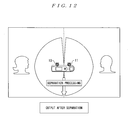
- Figure 12 is an application to a voice memo device.
- a voice memo device has been used for making a memo of a conference in a conference or meeting.
- a recorded content may be difficult to listen because a surrounding noise and voices of two persons are recorded simultaneously.
- two MICs 10 and 11 are directed to two speakers respectively, and contents of conversation at each person's side is enhanced and recorded by the sound source separation device 1, so that it is easy to listen at a later day.
- the sound source separation device 1 as described above, voices of facing two persons can be separated and collected, so that the device can be applied to a voice memo for minutes of conference and simultaneous speech recognition for each of two person's speech in minutes of conference.
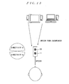
- Figure 13 shows an example of application to a simple hands-free device and a microphone for a speech recognition device.
- a PC personal computer
- a PC without echo canceller function requires a countermeasure such as a headset microphone or the like to reduce the echo from loudspeaker to a MIC.
- an echo canceller function may be implemented as software inside a PC, or a hands-free device with built-in echo canceller function may be connected to outside of the PC.
- the echo canceller function is implemented inside the PC, played speech to a loudspeaker and input speech from microphone needs to be synchronized, and thus there are problems for implementation that a delay between played speech and input speech is large, a delay depends on PC model, and so on. It is costly that the hands-free device with built-in echo canceller function is connected to outside of the PC.
- the MICs 10 and 11 have to be arranged between a loudspeaker and a speaker, they are not required to be synchronized with a played signal of the loudspeaker. Because sound source separation can be performed based on software installed on the PC by preparing two MICs 10 and 11 and feeding signals from them into PC, its implementation is easy. In addition, it considered as an environment under which speech recognition is performed most frequently at home that users speak voice command toward a controlled device such as a television.
- a loudspeaker of the television or the like controlled device is placed facing toward a speaker side from a controlled device side, and it may happen that the speaker wants to speak a control command to a microphone device in a situation where speech or various guidance is coming from the loudspeaker. In this situation, it is necessary that the sound coming from loudspeaker to the microphone device is attenuated by some sort of means.
- a speech from the controlled device can be easily separated from a speech coming from the loudspeaker by using the sound source separation device 1, thereby speech recognition performance is improved.
- speech recognition technology which realizes the followings features: (1) separation between speech of a driver in a driver's seat and speech of a passenger in a passenger's seat (hereinafter referred to as " speech of the driver's seat and the passenger's seat"), (2) movement of a speaker's head position is allowable, (3) both large beam width and separation performance are achieved at the same time, (4) function is provided using a few MICs, and (5) a driver or a passenger is not forced to be quiet during use of speech recognition.
- the MICs may be installed such that a mounting direction roughly faces toward front when the MICs are mounted or a directional characteristics control function described later may be provided. Since beam width is originally large in the sound source separation device 1, precise positioning is not required. In addition, when they are installed in the mounting position L2, it may be useful for suppressing a reflection from backside to devise a microphone module or use a directional microphone. Conditions of the evaluation experiment are shown in Figure 15 , and results of the evaluation experiment after sound separation are shown in Figures 16A and 16B .
- Figure 16A in a case of simultaneous speech of two speakers in a car (in-car simultaneous speech), when processing was not applied, i.e., in a conventional method 1 which uses only 1-channel microphone, 29% (in stopping), 27% (in driving at 60 km/h) were shown, and when the present speech separation technique was applied, improvements were shown as 78%(in stopping), 78%(in driving at 60 km/h).
- Figure 16B shows the evaluation result of the percentage of the case that a speech of the passenger's seat side is speech-recognized in mistake for a speech of the driver's seat side or a speech of the driver's seat side is speech-recognized in mistake for a speech of the passenger's seat side.
- the conventional method 2 is a scheme which performs adaptive beamforming processing while estimating arrival directions of a target sound and a noise, emphasizes the target sound and the noise, and performs spectral subtraction in a frequency domain to subtract a signal of the emphasized noise from a signal of the emphasized target sound, for preventing the effect of estimation error of arrival direction
- processing was performed in which a target sound and a noise are both assumed to be known (arrive from a fixed direction), and an optimum value of an adaptive beamformer section is obtained, and then a target sound (a speaker 1) and a noise (a speaker 2) are simultaneously played, and the target sound is extracted (see Figure 16A ).
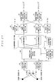
- Figure 17 shows a configuration of a sound source separation system according to the second embodiment.
- inputs from the MICs 10 and 11 are converted into frequency components at first by the spectrum analysis sections 20 and 21 in the above described first embodiment
- a directional null is formed in a time domain by beamformers 80 and 81 at first, and generate a signal in which a signal from a specific arrival direction is attenuated by beamformers 80 and 81, and then conversion into frequency components is performed by the spectrum analysis sections 20 and 21.
- those having the same functions as in Figure 1 are given the same reference numbers.
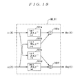
- Configurations of the beamformers 80 and 81 are implemented by performing filter processing configured as a form of an FIR filter or the like as shown in Figure 18 .
- coefficients of the FIR filter can be obtained by converting the weighted coefficients that are in complex conjugate pairs in the frequency domain shown in Figure 3 into filter coefficients in a time domain.
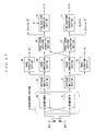
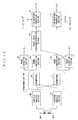
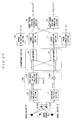
- Figure 19 and Figure 20 are diagrams which show configurations of sound source separation systems according to the third embodiment.
- the target sound spectrum extraction sections 50 and 51 shown in Figure 1 and Figure 17 are implemented as the configuration shown in Figure 5 , and are configured to perform sound source separation processing using an optimum threshold value obtained by experiment.
- thresholds are set to "0" in the coefficient conversion sections 501 and 511 in the target sound spectrum extraction sections 50 and 51 by checking only signs in the calculation sections 500 and 501, if it is positive, power spectrum information of a sound source signal coming from right direction (0 degree to 90 degrees) is extracted, and if it is negative, power spectrum information of a sound source signal coming from left direction (-90 degrees to 0 degree) is extracted. Accordingly, the entire configurations shown in Figure 1 and Figure 17 are simplified to configurations as shown in Figure 19 and Figure 20 .
- a target sound spectrum extraction section 90 in Figure 19 and Figure 20 is implemented as a configuration shown in Figure 21 .
- power spectrum information of the beamformers 30 and 31 computed by the power computation sections 40 and 41 is inputted to a difference calculation section 900 inside the target sound spectrum extraction section 90. Then, subtraction processing is performed by a subtractor 900a, and sound source signals only from targets direction are extracted by coefficient conversion sections 910 and 920 respectively.
- the coefficient conversion section 910 is a block for extracting a sound source from right direction (0 degree to 90 degrees), and if an input is positive, its spectrum information is outputted as information coming from right direction (0 degree to 90 degrees), and if an input is negative, spectrum information is considered as information of a sound source arriving from a direction other than the target, and thus not outputted.
- the coefficient conversion section 920 is a block for extracting a sound source from left direction (-90 degrees to 0 degree), and if an input is negative, its spectrum information is outputted as information coming from left direction (-90 degrees to 0 degree), and if an input is positive, spectrum information is considered as information of a sound source arriving from a direction other than the target, and thus not outputted.
- the above described operation allows separation of sound signals arriving from left and right with respect to the perpendicular line to the straight line connecting the two MICs 10 and 11.
- Configurations of the sound source separation system shown in Figure 19 and the sound source separation system shown in Figure 20 are different in that beamforming processing is performed in a frequency domain or a time domain. In Figure 19 , beamforming processing is performed in a frequency domain, and in Figure 20 , it is performed in a time domain.
- Figure 22 is a diagram which shows a configuration of a sound source separation system according to the fourth embodiment.
- Spectral subtraction sections 100 and 101 shown in the figure performs spectral subtraction processing for eliminating a stationary noise, a diffuse noise, and the like whose arrival direction is unknown, which have superimposed on each target sound extracted by the target sound spectrum extraction sections 50 and 51.
- This configuration is effective when it is used in an environment in which there is a fan noise of an air-conditioner or a projector, or the like in a meeting room, but is particularly effective when it is used in an automobile.
- the spectrum subtraction processing there are a type in which a voice activity detection is performed for an input signal of one MIC, a noise spectrum in non-speech section is estimated, and a previously estimated noise component is scaled and subtracted from the speech section; and a type in which, using a spectrum of a signal in which a noise is dominantly recorded and a spectrum of a signal in which a speech is dominantly recorded, a spectrum of the signal in which the noise is dominantly recorded is scaled and subtracted from a spectrum of the signal in which the speech is dominantly recorded. Processing based on a 1-microphone system is enough for speech recognition in many cases, and this is employed also in the present embodiment. To support this, in the sound source separation system according to the present embodiment, a voice activity detection section 110 and the spectral subtraction sections 100 and 101 are newly added to the sound source separation system according to the first embodiment.
- sound sources R1 and R2 are target sounds
- a sound source R3 represents noises such as a stationary noise whose arrival direction is unknown and a diffuse noise. Many of these noises do not have clear directivity.
- a noise having weak directivity is often contained in a target sound spectrum extraction section which extracts a sound source from its direction, and a noise having no directivity, an impact noise occurred when a joint of a road is passed, or the like is often detected in spectrums extracted from left and right alternately.
- these noises can be eliminated by the spectral subtraction sections 100 and 101.
- a continuous spectral subtraction which does not require voice activity detection section may be used.
- Figure 23 shows a configuration of a sound source separation system according to the fifth embodiment.
- a measure is shown in a case where the two target sound sources R1 and R2 to be separated are placed far away from positions symmetrical with respect to the perpendicular line to the straight line connecting the two MICs 10 and 11.
- the sound source separation system includes arrival direction estimation section 120 for detecting approximate positions of two target sound sources R1 and R2, and delay operation is applied to input of one of the MICs by a directional characteristics control section 140 so as to make the two target sound sources R1 and R2 to be separated virtually symmetrical with respect to the perpendicular line to the straight line connecting the two MICs 10 and 11 as much as possible with approximate sound source arrival direction information of the two target sound sources R1 and R2 based on its positions estimated by the arrival direction estimation section 120.
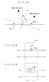
- Figure 24 shows a situation where two sound sources R1 and R2 are symmetrical with respect to a straight line which has rotated by ⁇ with respect to the perpendicular line to the straight line connecting the MICs 10 and 11.
- a situation equivalent to ⁇ rotation can be achieved by applying a certain delay ⁇ d to a signal captured by one of the MICs.
- filter parameters of the beamformers 30 and 31 which are optimum for separating two sound sources are prepared based on positional relationships with respect to the perpendicular line to the straight line connecting the two MICs for some combinations of two sound sources, beamformer's filter parameters which are assumed to be optimum for separating the two sound sources in a current situation are selected by beamformer control based on approximate arrival direction information of the two sound sources from the arrival direction estimation section 120, and the selected beamformer's filter parameters are set in the beamformers 30 and 31.
- Figures 25A and 25B show configuration examples of the directional characteristics control section 140.
- a configuration example shown in Figure 25A shows an example in which a certain delay ⁇ d is applied to each frequency component in a frequency domain of a signal captured by one of the MICs.
- x 1 ( ⁇ ) is multiplied by e -j ⁇ by the multiplier 100a, thereby achieving a delay operation.
- filtering processing needs to be performed by a delay device 100b in an FIR filter form as shown in Figure 25B .
- a half of the delay may be applied to each of inputs of both the MICs so that the same quantity of the delay operation is achieved as an entire processing.
- a delay ⁇ d instead of applying a delay ⁇ d to a signal captured by one of the MICs, a delay ⁇ d/2 is applied to the signal captured by the one of the MICs and a delay - ⁇ d/2 is applied to a signal captured by the other of the MICs, so that a total delay difference can be ⁇ d.
- Figure 26 is a diagram which shows a configuration of a sound source separation system according to the sixth embodiment.
- the sound source separation system according to the present embodiment has a configuration which lays weight on audibility in consideration of application to hands-free call in an automobile and the like.
- speech of the driver's seat and the passenger's seat can be separately extracted using the foregoing scheme.
- one whose arriving direction is unknown and diffuse noise such as a blower sound of an air conditioner, a road noise, and a wind noise cannot be eliminated by the foregoing method.
- influence of these noises can be eliminated by adding spectrum subtraction processing in a subsequent stage of the process, and this is most suitable for applications such as speech recognition in which sound quality in terms of audibility is not taken in account.
- a residual unremoved noise called a musical noise may become a problem.
- a noise such as a diffuse noise whose directivity continually varies may be allocated into left and right separation results irregularly, thereby degrading sound quality.
- the sound source separation scheme according to the present invention is not affected by time variation of a microphone gain, post-filter processing which is typically used in a subsequent stage of microphone array processing is added in a previous stage of beamformer processing so that a diffuse noise, a stationary noise, and the like are reduced, thereby a musical noise after sound source separation is prevented.
- FIG. 27 is a diagram which shows a configuration of a sound source separation system according to the seventh embodiment.
- This sound source separation system illustrates a configuration in which three MICs 10, 11 and 12 are used to separate three sound sources.
- FIG. 1 using MICs 10 and 12 and MICs 10 and 12, left and right sound source signals are separated with respect to a perpendicular line to a straight line connecting respective two MICs, and using a total of four sound source signals which have been separated using two pairs of MICs, a sound source R3 arriving from the vicinity of front of the MICs 10 and 11 is finally separated by a target sound extracting section 160.
- the separation section b0 can separate a sound source signal S A ( ⁇ ) from zone A and a signal in which sound source signals S Bmix ( ⁇ ) and S Cmix ( ⁇ ) from zones B and C are mixed, and similarly the separation section b1 can separate a signal in which sound source signals S Amix ( ⁇ ) and S Bmix ( ⁇ ) from zones A and B are mixed and a sound source signal S C ( ⁇ ) from zone C, and thus S A ( ⁇ ) and S C ( ⁇ ) have been separated in this stage. From the four signals obtained in this way, S B ( ⁇ ) can be obtained by a predetermined operation in a power spectrum domain by the target sound extraction section 160. As used herein, S Amix ( ⁇ ), S Bmix ( ⁇ ), S Cmix ( ⁇ ) represent respective signals which mixed with other signals.
- Figure 29 shows an example of installation of a unidirectional microphone. While, in general, when directional microphones are used in this way, performance as designed may not be achieved at a beamformer section of an array microphone due to uneven directional characteristics of each MIC or the like, certain performance can be achieved without being affected by uneven directional characteristics as in the case where the present scheme is not affected by uneven sensitivity of MIC elements by its nature.
- a processing scheme in the target sound extraction section 160 will be described in detail with reference to Figures 30 to 32 .
- a processing scheme shown in Figure 30 is a processing scheme similar to 2-channel spectral subtraction processing.
- a target sound S B ( ⁇ ) can be obtained by performing subtraction on them by a subtractor 100a.
- minimum value calculations 102a and 102b are used instead of the adders 101a and 101b shown in Figure 31 .
- O.E.F is preferably around 1.0 in Figure 32 .
- minimum value calculation is performed in Figure 32
- maximum value calculation may be performed instead of minimum value calculation.
- operation for obtaining optimum separation performance as much as possible can be performed by applying a delay to an input signal outputted from a MIC so as to virtually change an arrival direction of a sound source.
- Figure 33 shows a usage example of the sound source separation system according to the present embodiment.
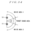
- shown example has a directional characteristics to capture a speech from the front side of the PC by using three MICs 10, 11 and 12 with a small area for implementation.
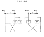
- directional characteristics control means applies a delay to an output signal from one of the two MICs 10 and 11 to create a virtual microphone position of the third channel as shown in Figure 35B , so that 3-microphone input shown in Figure 35A can be virtually realized.
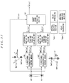
- Figure 37 shows a configuration example of a sound source separation device system according to the present embodiment.
- Directional characteristics control means 141 and 142 are composed of spectrum analysis sections 20 and 21 and delay elements which performs delay processing. In a processing sequence, delay processing may be performed after spectrum analysis processing (Type. 1 in the figure), or spectrum analysis processing may be performed after delay processing (Type. 2 in the figure).
- Output signals of the directional characteristics control means 141 and 142 are processed by the beamformers 30 and 31 and the power computation sections 40 and 41 or the like, which are blocks in later half part of the present technique from NBF, and the processed signals are inputted to a target sound extraction section 52.
- Figure 38 and Figure 39 examples of processing schemes in the target sound extraction section 52 are shown.
- Figure 38 shows one example of a processing scheme in which ⁇ 1 and ⁇ 2 are angles symmetrical with respect to the perpendicular line to the straight line connecting the MICs 11 and 12
- Figure 39 shows one example of a processing scheme in which ⁇ 1 and ⁇ 2 are angles asymmetrical with respect to the perpendicular line.
- Figure 40 is a diagram which shows a configuration of a speech recognition system for controlling on-vehicle equipment according to the ninth embodiment.
- the sound source separation device 1 according to the present invention is applied to the speech recognition system for controlling on-vehicle equipment provided in a vehicle such as an automobile.
- speech of the driver's seat and the passenger's seat are captured by the two MICs 10 and 11, the speech of the driver's seat and the passenger's seat are separated by the sound source separation device 1.
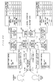
- the speech recognition system for controlling on-vehicle equipment stores a passenger's seat side recognition vocabulary list 190, a driver's seat side recognition vocabulary list 191, a passenger's seat side valid vocabulary list 210, and a driver's seat side valid vocabulary list 211 in a storage device, as characteristic data of this system.
- the driver's seat side recognition vocabulary list 191 is a list of candidates of vocabulary spoken from the driver's seat side
- the passenger's seat side recognition vocabulary list 190 is a list of candidates of vocabulary spoken from the passenger's seat side.
- the driver's seat side valid vocabulary list 211 is a list of valid vocabulary in the driver's seat side depending on a state of the vehicle (a running state of the automobile and other driving states).
- the passenger's seat side valid vocabulary list 210 is a list of valid vocabulary in the passenger's seat side depending on a state of the vehicle. "Valid” used herein refers to a state in which output of a control command corresponding to a vocabulary item (a voice command) is allowed.
- Speech spoken by a driver in a driver's seat and a passenger in a passenger's seat are captured by the two MICs 10 and 11, separated into a speech of the driver's seat and a speech of the passenger's seat by the sound source separation device 1, and then inputted to voice activity detection sections 170 and 171 and speech recognition sections 180 and 181, which have been prepared for the driver and the passenger in the passenger's seat respectively.
- speech sections of the both speaker can be accurately separated by the passenger's seat side voice activity detection section 170 and the driver's seat side voice activity detection section 171, as well as information in which a speech of the other speaker is suppressed can be provided to the passenger's seat side speech recognition section 180 and the driver's seat side speech recognition section 181, so that speech recognition processing without being affected by a speech of the other speaker can be accurately performed.
- speech recognition sections 180 and 181 are provided with the passenger's seat side recognition vocabulary list 190 and the driver's seat side recognition vocabulary list 191 for indicating what kind of vocabulary should be recognized independent of a state of the system, which are dedicated to the sections respectively.
- Each of the speech recognition sections 180 and 181 performs speech recognition according to these vocabulary lists and outputs a speech recognition result to a control section/state transition section 200.
- a state transition section 201 provided in the control section/state transition section 200 can transit to a next state based on the speech recognition result and a current state.
- a control section 202 provided in the control section/state transition section 200 checks which voice commands can be responded (a control command can be outputted), based on the current state obtained from the state transition section 201 and the speech recognition result from the speech recognition sections 180 and 181, and the passenger's seat side valid vocabulary list 210 and the driver's seat side valid vocabulary list 211 which have been prepared for the passenger's seat side and the driver's seat side respectively.
- the valid vocabulary lists 210 and 211 shown in the figure when a set of a state and a voice command corresponds to "O", response to the voice command is allowed.
- voice commands to which a response is allowed when a state is “driving” are “more”, “turn on light”, and “ cool down”, and voice commands to which a response is forbidden are "air-conditioner control", "CD”, and "MD”.
- simultaneous speech of a driver in a drive's seat and a passenger in a passenger's seat can be recognized at the same time, and whether speech is from the driver's seat or the passenger's seat can be surely detected and recognized even if either one speaks, so that behavior of a passenger is not limited, and a speaker and a response to a voice command of the speaker can be designed individually.
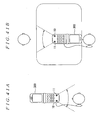
- Figures 41A and 41B show a mobile phone 300 according to the present embodiment.
- the mobile phone 300 is mounted with MICs 10 and 11 and a not shown sound source separation device.
- This mobile phone 300 is normally used for visual telephone, and can be used as a sound collecting microphone by switching a mode.
- Figure 41A is a diagram which shows that the MICs 10 and 11 operate as a sound collecting microphone for visual telephone
- Figure 41B is a diagram which shows that the MICs 10 and 11 operate as a microphone.
- At least two MICs are arranged separately from each other, directional nulls are formed in a time domain or a frequency domain at angles symmetrical with respect to a perpendicular line to a straight line connecting the two MICs by beamformers, signals are converted into a frequency domain if a directional null is formed in a time domain, a difference between power spectrums of the both beamformers is calculated, and coefficient conversion is performed on the obtained result, and thereby directional characteristics having some width with respect to left and right directional nulls are formed, so that sound source separation can be performed.
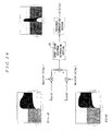
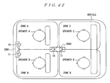
- Figure 42 shows an example in which a target sound in zone A is extracted in a situation where the target sound to be extracted locates in zone A (for example, a zone of a driver's seat) and interfering sounds locates in places other than that (zone B, zone C and zone D).
- an array microphone 2001 ((For example, it is located in the front of a car cabin) for example, it is mounted at a rear-view mirror) is used, although sounds locating in zone A/C (for example, zones of a driver's seat and a seat behind it) and zone B/D (for example, zones of a passenger's seat and a seat behind it) can be separated, sounds locating in zone A (for example the zone of the driver's seat) and zone C (for example, the zone of the seat behind it) cannot be separated.
- zone A/C for example, zones of a driver's seat and a seat behind it
- zone B/D for example, zones of a passenger's seat and a seat behind it
- a sound from zone A/B and a sound from zone C/D can be separated.
- a sound from zone A/C and a sound form zone B/D can be separated by the microphone array 2001.
- the sound from zone A/C obtained by using the microphone array 2001 is compared with the sound from zone A/B obtained by using the microphone array 2002 for each frequency domain, and thereby a frequency component existing in both of the sounds in common can be separated as a sound from zone A. Sounds also from zones B, C and D can be obtained by similar processing respectively.
- Figure 43 a situation is assumed where equipment is operated by speech recognition in an environment such as an automobile.
- Figure 44 shows a relation between a guidance speech for the equipment operation and speech of speakers.
- a guidance speech such as "Please say your destination.” is played from a loudspeaker 15 to prompt timing of speech of a speaker A, and then a machine sound such as "pip" is played, and after that, the speaker A speaks a voice command.
- a situation where the speaker A starts speak during guidance speech is played occurs as shown in Figure 44 , thereby speech recognition performance degrades.
- an echo canceller is generally used to adaptively estimate and eliminate a guidance sound mixed in a sound captured from the MIC 10.
- spectral subtraction is performed with respect to on input signal to the MIC 10 after frequency analysis ( Figure 45 , Figure 46 ), and a major contained speech which is guidance speech or speech of speaker A for each frequency component is estimated, and only a frequency component in which major contained speech is the speech of the speaker A is extracted as speech of the speaker A ( Figure 47 , Figure 48 ).
- a filter section 1001 is a filter which simulates an acoustic reflection path from the loudspeaker 15 to the MIC 10, and it may be obtained previously using an impulse response from the loudspeaker 15 to the MIC 10 or may be dynamically obtained by adaptive filter processing.
- a gain operation section 1002 is a section for determining an over subtraction factor that is used in performing spectral subtraction, and selects one gain from about 1 to 10 according to volume of the loudspeaker 15 and uses the selected gain.
- a target sound extraction section 1003 in Figure 45 performs processing as shown in Figure 46 based on outputs from the gain operation section 1002 and the spectrum analysis section 21 and outputs a signal of processing result to a time waveform conversion section 1004.
- a threshold calculation section 1011 in Figure 47 determines a threshold th based on average energy of guidance speech.
- a target sound extraction section 1012 in Figure 47 performs processing as shown in Figure 48 based on outputs from the threshold calculation section 1011 and the spectrum analysis section 21 and outputs a signal of processing result to the time waveform conversion section 1004.
- th mim shown in Figure 48 becomes a threshold value for determining that X Far ( ⁇ ) shown in the figure is a valid input.
- the time waveform conversion section 1004 performs processing similar to the time waveform conversion sections 70 and 71 of the first embodiment.
- the conventional method can handle a situation where only the speaker A speaks by the above described configuration as shown in Figure 43 .
- the speaker B speaks as shown in Figure 50 when there are not only the speaker A (for example, an occupant in the driver's seat) but also the speaker B (for example, an occupant in the passenger's seat) as shown in Figure 49 , and this situation cannot be handled by the above described configuration.
- this situation can be handled by combining the present technique with guidance speech elimination sections 1021 and 1022 shown in Figure 45 or 47 .
- an input on which a guidance speech, a speech of the speaker A, and a speech of the speaker B are superimposed is given to the MIC 10 and the MIC 11 in a situation where a guidance speech is played from the loudspeaker 15, and both the speaker A and the speaker B speak simultaneously.
- the guidance sound deleting section 1021 and the guidance speech elimination section 1022 eliminate the guidance speech by the method shown in Figure 45 or 47 , and as a result, outputs a signal on which both speech of the speaker A and the speaker B are superimposed.
- a frequency component is inputted to the present technique ( Figure 1 ) as is without being converted back to a time waveform. Processing of a spectrum analysis section is omitted since frequency component information is inputted in the latter stage of the present technique, and it is directly inputted to a beamformer section and processed by applying the present technique, so that a speech of the speaker A and a speech of the speaker B can be obtained as an output result independently, and therefore reliability and performance of the speech recognition device and flexibility of application can be greatly enhanced.
- each functional block of a sound source separation system is implemented by a program, it may be implemented by hardware using circuitry or the like.
- the present invention is applicable to all of industries in which sound sources needs to be accurately separated such as for a speech recognition device, a car navigation system, a sound collector, a recorder, and control of equipment by a voice command.
Landscapes
- Engineering & Computer Science (AREA)
- Health & Medical Sciences (AREA)
- Physics & Mathematics (AREA)
- Acoustics & Sound (AREA)
- Audiology, Speech & Language Pathology (AREA)
- Human Computer Interaction (AREA)
- Computational Linguistics (AREA)
- Multimedia (AREA)
- Otolaryngology (AREA)
- Signal Processing (AREA)
- Quality & Reliability (AREA)
- Circuit For Audible Band Transducer (AREA)
- Obtaining Desirable Characteristics In Audible-Bandwidth Transducers (AREA)
Abstract
Description
- The present invention relates to a sound source separation device, a speech recognition device, a mobile telephone, a sound source separation method, and a program which uses a plurality of microphones and separates a sound source signal of a target sound source from a signal which consists of a plurality of acoustic signals emitted from a plurality of sound sources such as a plurality of speech signals and various background noises.
- When a specific speech signal or the like is to be recorded under various environments, it is difficult to record only a signal of a target sound using a microphone since there are various noise sources in a peripheral environment, and therefore some sort of noise reduction processing or sound source separation processing is necessary.
As an example where such processing is especially needed, there is an automotive environment. Under an automotive environment, due to the spread of mobile phones, a microphone installed far from speaker's mouth in a car is typical situation of a telephone call using a mobile phone during driving, and thereby speech quality is significantly degraded. In addition, also when speech recognition is performed during driving under an automotive environment, because utterance is performed in similar condition, speech recognition performance is degraded. The current progress in speech recognition technology makes speech recognition much more robust against stationary noise than before. However, the current speech recognition technology has a problem of degradation of recognition performance when a plurality of speakers speaks simultaneously. Since the current speech recognition technology does not provide high speech recognition accuracy for a mixed simultaneous speech of two speakers, a passenger other than a speaker is not allowed to speak during the speech recognition device is used. Under this situation, behavior of the passenger is restricted. Although a principal independent component analysis method or the like have applied to separate such sound sources, it is not practical enough because of computational complexity, variations of the number of sound sources, and the like. - To solve the above described problems, various kinds of methods, which use a plurality of microphones installed in a car cabin and record only a speech from a certain direction, have been proposed. However, it is difficult to secure space for installing many microphones in a car cabin. Furthermore, it is also difficult to use microphones having uniform characteristics under the cost restriction. Therefore, a method is desired which allows the number of microphones to be as small as possible and uneven characteristic of the microphones.
Generally, when a plurality of microphones are used, the lower the cost of microphones, the larger the uneven sensitivity characteristics thereof, and it is said that uneven frequency characteristics is about ±3 dB. In processing of an addition type array such as a delay-and-sum array in microphone array technologies, these uneven characteristic only prevents microphone array performance to be achieved as designed. However, in a so-called subtraction type array such as an adaptive array, these uneven characteristic may degrade performance especially in low frequencies less than or equal to about 1 kHz compared to a case where one microphone is used. - Uneven characteristic of microphones as sensors are a critical problem for the microphone array technology. To solve this problem, methods for uniforming sensitivities of a plurality of microphone elements have been proposed in
Patent Documents 1 to 5, etc.
Conventionally, as for a microphone array that utilizes an adaptive beamforming processing technology which has a great effect with a few number of microphones, various methods such as a generalized sidelobe canceller (GSC), a Frost type beamformer, and a reference signal method have been known as described in, for example, Non-PatentDocuments - The adaptive beamforming processing is basically a processing to suppress noise by a filter which forms a directional beam having a directional null (blind spot) in a direction of a noise source, and a generalized sidelobe canceller is known to have relatively high performance especially among them. However, the GSC has a problem that a target signal is suppressed and degraded when the target signal is arrived from a direction different from a direction of a specified target sound source. To deal with this problem, Patent Documents 6 and 7 discloses a method which performs processing in a frequency domain so that a computational complexity is reduced, and a direction of a speaker and a direction of a specific noise are successively detected by using filter coefficients in the frequency domain, a target sound is separated from a noise other than the target sound to some extent, and spectral subtraction is applied as well, so that a noise from unknown arrival direction and a diffuse noise are reduced.
[Patent Document 1]JP5-131866A
[Patent Document 2]JP2002-99297A
[Patent Document 3]JP2003-153372A
[Patent Document 4]JP2004-343700A
[Patent Document 5]JP2004-289762A
[Patent Document 6]JP2001-100800A
[Patent Document 7]JP2000-47699A
[Non-Patent Document 1] The Institute of Electronics, Information and Communication Engineers, "Acoustic Systems and Digital Processing"
[Non-Patent Document 2] HAykin, "ADAptive Filter Theory (Prentice HAll)" - In the technology which combines the adaptive beamformer with the spectral subtraction as described in the Patent Documents 6 and 7, a reference signal, which is a suppressed target sound, needs to be generated as an input signal of an adaptive filter section. If there is an uneven sensitivity of microphone elements, the target sound cannot be sufficiently suppressed and thus the target sound is contained in both the reference signal and a target signal in the adaptive filter section. Therefore the target sound is distorted and quality of the sound is degraded as a result of application of adaptive filter processing. Also in a closed space where an initial reflection is strong, a target sound signal is leaked into a reference signal so that the similar phenomenon occurs.
To solve this problem, there is a method of compensating sensitivity of microphone elements, which measures a uneven characteristic of microphone elements in assembly process to generate data for compensation, and compensates the characteristic based on the data when the microphone elements are used, or which calibrates individual differences of sensitivities of microphone elements and successive changes caused by aging change of components or peripheral temperature using a reference signal from a specific direction while in use. However, there are problems about increase of production cost, when a reference signal should be played, how to determine whether or not a recorded signal contains only a reference signal, and so on. - Paying attention to operation of an adaptive filter, in general, if there is a high correlation between a reference signal and a target signal, estimation process of the adaptive filter cannot perform well and thereby estimation accuracy is significantly degraded. As an example, there is a case where a target sound and a noise are both speech signals.
A similar problem occurs in an echo canceller, and in an adaptive filter which estimates an echo mixed from a far-end signal into a near-end signal, when two persons speak simultaneously at far and near ends, a so-called double-talk state occurs and thereby performance of the echo canceller is degraded. Therefore, it is an important condition to maintain the performance how precise a double-talk state is detected in order to stop parameter estimation of an adaptive filter or slow down the speed of the estimation. - Therefore, also in the case of the adaptive filter, if a target sound and a specific noise are both speech, a state in which the both are speaking needs to be detected. The more frequent this state is, the more frequent adaptive filter estimation is stopped. As a result, there is a problem that noise reduction performance of the adaptive filter is degraded.
Further, in a situation where a large diffuse noise such as a noise of a running car is generated, estimation accuracy of the adaptive filter is degraded due to the diffuse noise. And as a result, filter parameter estimated by adaptive filter degrades an estimation accuracy of arrival direction of a speaker and a specific noise, and thus overall system performance is degraded. - In addition, in the case that the above method described in the Patent Documents 6 and 7 is applied to a noise component suppression device using a low-cost microphone for an automobile or the like, a desired operation cannot be achieved as an entire device if an initial reflections of a sound source in a car cabin is strong, a diffuse noise component is large, a uneven characteristic of used microphone elements is large (about ±3 db), and a target signal and a specific noise are generated simultaneously and their correlation is high because a driver and a passenger speak simultaneously, or so on.
The present invention is made in view of the above described problems, and is intended to provide a sound source separation device, a speech recognition device, a mobile telephone, a sound source separation method, and a program which allow to separate a sound source signal of a target sound source from a mixed sound which includes sound source signals emitted from a plurality of sound sources without being affected by uneven sensitivity of microphone elements.
To solve the above described problems, an invention according toclaim 1 provides a sound source separation device for separating a sound source signal of a target sound source from a mixed sound which includes sound source signals emitted from a plurality of sound sources using at least two microphones arranged separately from each other comprising: beamforming means for performing a first beamforming processing to attenuate a sound source signal arriving from a predetermined direction by performing computations using first coefficients on an output signal of said microphones, and performing a second beamforming processing to attenuate a sound source signal arriving from a direction symmetrical to said predetermined direction with respect to a perpendicular line to a straight line connecting the two microphones by performing computations using second coefficients which are complex conjugate of said first coefficients in a frequency domain on the output signal of said microphones; power computation means for computing power spectrum information with respect to each of sound source signals obtained by said beamforming means; and target sound spectrum extraction means for extracting spectrum information of a target sound source based on a difference between the power spectrum information calculated by said power computation means. - According to this invention, the sound source separation device provides a directional characteristics which is not affected by sensitivities of microphone elements, and allows to separate a sound source signal of a target sound source from a mixed sound which includes sound source signals emitted from a plurality of sound sources without being affected by uneven sensitivity of the microphone elements.
An invention according toclaim 2 is the sound source separation device according toclaim 1, wherein said beamforming means applies said first beamforming processing and said second beamforming processing to each of a combination of any two microphones among three microphones which arranged separately from each other and another combination of two microphones among said three microphones. - According to this invention, a sound source signal from a target sound source which locates in each area whose boundary is a perpendicular line to a straight line connecting two microphones among three microphones.
An invention according toclaim 3 is the sound source separation device according toclaim
According to this invention, directional characteristics can be compensated to its optimum condition by applying a delay, and separation performance of sound sources can be improved. - An invention according to claim 4 is the sound source separation device according to
claim 3, wherein said directional characteristics control means virtually generates output signals of three microphones by applying a delay to an output signal of at least one microphone among two microphones.
According to this invention, since output signals from three microphones can be virtually generated, a sound source signal arriving from a direction of a perpendicular line to a straight line connecting two microphones can be separated and extracted using only the two microphones. - An invention according to
claim 5 is the sound source separation device according toclaim 3 or 4, further comprising arrival direction estimating means for estimating a arrival direction of said sound source signal, wherein said directional characteristics control means applies a delay to an output signal of the microphone such that two sound sources virtually locate symmetrically with respect to a perpendicular line to a straight line connecting the two microphones based on an arrival direction estimated by said arrival direction estimating means.
According to this invention, delay operation can be performed such that high separation performance of sound sources is obtained. - An invention according to claim 6 is the sound source separation device according to any one of
claims 1 to 5, further comprising spectral subtraction means for performing spectral subtraction processing on the power spectrum information extracted by said target sound extraction means.
According to this invention, a stationary noise whose arrival direction is unknown, a diffuse noise, and the like can be suppressed by performing the spectral subtraction processing. - An invention according to claim 7 is the sound source separation device according to any one of
claims 1 to 6, further comprising stationary noise reduction means for performing processing to reduce noise before the processing by said beamforming means is performed.
According to this invention, generation of a perceptually unpleasant noise such as a musical noise can be reduced.
An invention according toclaim 8 provides a speech recognition device comprising speech recognition means for performing speech recognition of a sound source signal separated by the sound source separation device according to any one ofclaims 1 to 7. - According to this invention, highly accurate speech recognition can be performed based on a separated sound source signal with high accuracy.
An invention according to claim 9 is the speech recognition device according toclaim 8, further comprising recognition vocabulary list storage means for storing a driver's seat side recognition vocabulary list which is a list of candidates of vocabulary spoken from a driver's seat side of a vehicle and a passenger's seat side recognition vocabulary list which is a list of candidates of vocabulary spoken from a passenger's seat side, wherein said speech recognition means performs speech recognition processing of a sound source signal separated by said sound source separation device based on the driver's seat side recognition vocabulary list and the passenger's seat side recognition vocabulary list stored in said recognition vocabulary list storage means. - According to this invention, since the speech recognition device performs speech recognition processing based on the passenger's seat side recognition vocabulary list and the driver's seat side recognition vocabulary list stored in the recognition vocabulary list storage means, an optimal vocabulary item can be selected from a vocabulary list separately between a driver's seat side and a passenger's seat side so that accurate speech recognition can be performed.
An invention according toclaim 10 is the speech recognition device according toclaim 8 or 9, further comprising: state transition means for managing a current state of a vehicle; valid vocabulary list storage means for storing a valid vocabulary list of the passenger's seat side and the driver's seat side depending on a state of the vehicle; and control means for determining whether a vocabulary item recognized by said speech recognition means is valid or not based on the current state of the vehicle managed by said state transition means and the vocabulary list stored in said valid vocabulary list storage means, and controlling depending on the determination result. - According to this invention, control contributes to the comforts of persons in vehicle because validness of recognized vocabulary item can be determined based on a current state of a vehicle and a valid vocabulary list, and control can be performed depending on the determination result. In addition, a valid vocabulary list and contents of control can be designed freely so that flexibility can be given to application design using speech recognition.
An invention according toclaim 11 provides a mobile phone comprising the sound source separation device according to any one ofclaims 1 to 7. - According to this invention, a mobile phone can be used as a sound collecting microphone in a medium sized conference room and the like.
An invention according toclaim 12 provides a sound source separation method comprising: a sound source signal receiving step of inputting sound source signals emitted from a plurality of sound sources to at least two microphones arranged separately from each other; a beamforming processing step of performing a first beamforming processing and a second beamforming processing to attenuate sound source signals arriving from predetermined directions symmetrical with respect to a perpendicular line to a straight line connecting two microphones respectively by performing computations using two weighted coefficients which are complex conjugate to each other in a frequency domain on an output signal of said microphone respectively; a power computation step of computing power spectrum information with respect to each of sound source signals obtained in said beamforming processing step; and a target sound spectrum extracting step of extracting spectrum information of a target sound source based on a difference between the power spectrum information calculated in said power computation step. - An invention according to claim 13 provides a program for causing a computer to perform: an output signal acquisition step of acquiring an output signal which includes sound source signals emitted from a plurality of sound sources are mixed from at least two microphones arranged separately from each other; a beamforming processing step of performing a first beamforming processing and a second beamforming processing to attenuate sound source signals arriving from predetermined directions symmetrical with respect to a perpendicular line to a straight line connecting two microphones respectively by performing computations using two weighted coefficients which are complex conjugate to each other in a frequency domain on the output signal acquired in said output signal acquisition step respectively; a power computation step of computing power spectrum information with respect to each of sound source signals obtained in said beamforming processing step; and a target sound spectrum extracting step of extracting spectrum information of a target sound source based on a difference between the power spectrum information calculated in said power computation step.
According to the present invention, a first beamforming processing and a second beamforming processing are performed for attenuating sound source signals arriving from predetermined directions symmetrical with respect to a perpendicular line to a straight line connecting two microphones respectively by performing operations using two weighted coefficients which are complex conjugate to each other in a frequency domain, thereby the sound source signals arriving from the predetermined directions symmetrical with respect to the perpendicular line to the straight line connecting two the microphones respectively are attenuated, and spectrum information of a target sound source is extracted based on a difference between respective power spectrum information of sound source signals obtained by the first beamforming processing and the second beamforming processing. Therefore, a directional characteristics which is not affected by sensitivity of microphone elements can be achieved, and a sound source signal from a target sound source can be separated from a mixed sound which contains sound source signals emitted from a plurality of sound sources without being affected by uneven sensitivity of the microphone elements. -
-
Figure 1 is a diagram which shows a basic configuration of a sound source separation system according to a first embodiment of the present invention; -
Figure 2 is a diagram which shows one example of a type of microphone according to the embodiment; -
Figure 3 is a diagram which shows a configuration of a beamformer section according to the embodiment; -
Figure 4 is a diagram which shows a configuration of a power computation section according to the embodiment; -
Figure 5 is a diagram which shows a configuration of a target sound spectrum extraction section according to the embodiment; -
Figure 6 is a diagram for describing a null beamformer according to the embodiment; -
Figure 7 is a diagram for describing the null beamformer according to the embodiment; -
Figure 8 is a diagram which shows one example of a directional characteristic of a difference result according to the embodiment; -
Figure 9 is a diagram which shows directional characteristic of conjugate beamformers when a sensitivity of microphone elements is varied according to the embodiment; -
Figure 10 is a diagram which shows directional characteristics of a single beamformer when a difference of sensitivity of microphone elements is varied according to the embodiment; -
Figure 11 is a diagram which shows a 360-degree directional characteristic of the sound source separation device according to the embodiment; -
Figure 12 is a diagram which shows an example of individual recording of two speakers using a directional characteristic of the sound source separation device according to the embodiment; -
Figure 13 is a diagram which shows an example of a simple hands-free device and a microphone for a speech recognition device using a directional characteristic of the sound source separation device according to the embodiment; -
Figure 14 is a diagram which shows mounting positions of microphones in an evaluation experiment according to the embodiment; -
Figure 15 is a diagram which shows conditions of the evaluation experiment according to the embodiment; -
Figures 16A and 16B are diagrams which show a result of the evaluation experiment according to the embodiment; -
Figure 17 is a diagram which shows a configuration of a sound source separation system according to a second embodiment; -
Figure 18 is a diagram which shows a configuration of a beamformer according to the embodiment; -
Figure 19 is a diagram which shows a configuration of a sound source separation system according to a third embodiment; -
Figure 20 is a diagram which shows a configuration of another sound source separation system according to the embodiment; -
Figure 21 is a diagram which shows a configuration of a target sound spectrum extraction section according to the embodiment; -
Figure 22 is a diagram which shows a configuration of a sound source separation system according to a fourth embodiment; -
Figure 23 is a diagram which shows a configuration of a sound source separation system according to a fifth embodiment; -
Figure 24 is a diagram which shows an example of directional characteristic control according to the embodiment; -
Figures 25A and 25B are diagrams which show a configuration of a directional characteristic control section according to the embodiment; -
Figure 26 is a diagram which shows a configuration of a sound source separation system according to a sixth embodiment; -
Figure 27 is a diagram which shows a configuration of a sound source separation system according to a seventh embodiment; -
Figure 28 is a diagram for describing positions of sound sources to be separated according to the embodiment; -
Figure 29 is a diagram which shows an example of installation of a unidirectional microphone according to the embodiment; -
Figure 30 is a diagram which shows one example of a configuration of a target sound extraction section according to the embodiment; -
Figure 31 is a diagram which shows one example of a configuration of the target sound extraction section according to the embodiment; -
Figure 32 is a diagram which shows one example of a configuration of the target sound extraction section according to the embodiment; -
Figure 33 is a diagram which shows an example of speech input to a personal computer using a sound source separation device according to the embodiment; -
Figure 34 is a diagram for describing a target sound area and a noise area according to an eighth embodiment; -
Figures 35A and 35B are diagrams for describing a delay operation according to the embodiment; -
Figure 36 is a diagram which shows a configuration example of directional characteristics control means according to the embodiment; -
Figure 37 is a diagram which shows a configuration example of a sound source separation device system according to the embodiment; -
Figure 38 is a diagram which shows one example of a processing scheme in a target sound extraction section according to the embodiment; -
Figure 39 is a diagram which shows one example of a processing scheme in the target sound extraction section according to the embodiment; -
Figure 40 is a diagram which shows a configuration of a speech recognition system for controlling on-vehicle equipment according to a ninth embodiment; -
Figures 41A and 41B are diagrams which shows a mobile phone according to a tenth embodiment; -
Figure 42 is a diagram which shows a microphone arrangement in a sound source separation system according to an eleventh embodiment; -
Figure 43 is a diagram which shows an environment to which a sound source separation system is applied according to a twelfth embodiment; -
Figure 44 is a diagram which shows a state of input speech to which the sound source separation system is applied according to the embodiment; -
Figure 45 is a diagram which shows a configuration of a guidance speech elimination section according to the embodiment; -
Figure 46 is a diagram which shows a configuration of a target speech extraction section according to the embodiment; -
Figure 47 is a diagram which shows another configuration of the guidance speech elimination section according to the embodiment; -
Figure 48 is a diagram which shows a configuration of a target speech extraction section in the another configuration of the guidance speech elimination section according to the embodiment; -
Figure 49 is a diagram which shows another environment to which the sound source separation system is applied according to the embodiment; -
Figure 50 is a diagram which shows another state of input speech to which the sound source separation system is applied according to the embodiment; and -
Figure 51 is a diagram which shows another configuration of the sound source separation system according to the embodiment. - Hereinafter, embodiments according to the present invention will be described with reference to the drawings.
-
Figure 1 is a diagram which shows a basic configuration of a sound source separation system according to the first embodiment of the present invention. This system is comprised of two microphones (hereinafter referred to as MIC) 10, 11 and a soundsource separation device 1. This soundsource separation device 1 includes a CPU that performs overall control and arithmetic processing, hardware including storage devices a ROM, a RAM, and a hard disk device, and software including a program, data, and the like stored in the storage devices, which are not shown. Function blocks shown inFigure 1 are implemented by these hardware and software. - The two
MICs MICs Figure 2 . TheMICs MICs - Frequency analysis is performed for each output of the
MICs spectrum analysis sections beamformers MICs beamformer section 3. Power of the filer output is computed bypower computation sections spectrum extraction sections beamformer section 3 under some conditions and performs the above described processings, so that the conventional problem of degradation of characteristics of a microphone array due to uneven sensitivity of microphone elements can be solved, and a directional characteristic which separates sounds from left and right with respect to the perpendicular line as described above can be achieved for a broad frequency band. Each functional block will be described in detail below. - First, a configuration of the
beamformer section 3 will be described with reference toFigure 3 . InFigure 3 , signals x1(ω) and x2(ω) which are decomposed for each frequency component byspectrum analysis sections multipliers adders beamformer section 3 forms directional nulls in symmetrical positions with respect to a perpendicular line to a straight line connecting theMICs - Next,
power computation sections Figure 4 . Thepower computation sections beamformer 30 and thebeamformer 31 to power spectrum information ps1(ω) and ps2(ω) by the following calculating equations.

- Next, the target sound
spectrum extraction sections Figure 5 . ps1(ω) and ps2(ω), which are outputs of thepower computation sections spectrum extraction sections spectrum extraction sections spectrum extraction sections difference calculation sections coefficient conversion sections
Thedifference calculation section 500 subtracts power spectrum information of thebeamformer 31 from that of thebeamformer 30 in thesubtractor 500a, and similarly thedifference calculation section 510 subtracts power spectrum information of thebeamformer 30 from that of thebeamformer 31 in the subtractor 501a, and their results are then inputted to thecoefficient conversion sections coefficient conversion sections coefficient conversion sections - Next, operation of the entire sound source separation device system will be described with reference to
Figure 1 .
Firstly, two omnidirectional ordirectional MICs MICs MICs spectrum analysis sections
The spectrum-analyzed two signals are filtered by the beamformers 30 and 31 in which directional nulls are formed symmetrically with respect to the perpendicular line to the straight line connecting theMICs beamformers power computation sections beamformers phase extraction sections beamformers power calculation sections spectrum extraction sections spectrum extraction section 50, power spectrum information of a sound source signal coming from left direction (-90 degrees to 0 degree) is extracted by the target soundspectrum extraction section 51. - In a case the power spectrum information extracted by the target sound
spectrum extraction section 51 is used as preprocessing of speech recognition processing, the relevant power spectrum information is sent to an acoustic parameter analysis section (not shown) in which acoustic analysis processing is performed on the power spectrum information. On the other hand, when the extracted power spectrum information of the sound source signals needs to be converted back to time signal, the phase information extracted by thephase extraction sections spectrum extraction sections waveform conversion sections - In the following, it will be proved that, if directional nulls in symmetrical positions with respect to the perpendicular line to the straight line connecting the two
MICs beamformers beamformer section 3, a directional characteristic (directivity) is not affected by sensitivity of microphone elements. - In a case where two microphone elements are used, as shown in
Figure 6 , a design example of a null beamformer in which a gain for a target direction θ1 is 1 and one directional null (gain 0) is formed in another direction θ2 will be described below.
When an output signal of the null beamformer is S(f)=[s1(f), s2(f)]', and an observed signal is X(f)=[x1(f), x2(f)]', W(f, θ1, θ2)=[w1(f), w2(f)]' which is a weighted coefficients vector of the null beamformer at a given frequency f (where ' denotes transposition operation) can be obtained by the following calculation. -

then,

- On the other hand, as shown in
Figure 7 , when a target direction and a null direction are set in directions line-symmetrical to the positions shown inFigure 6 with respect to the perpendicular line to the straight line connecting the twoMICs -

- Then,
-

- is calculated. A relationship between the two weighted coefficients vectors is:
-

- and therefore respective weighted coefficients have complex conjugate relationship.
Next, a directional characteristic is derived in thepower computation sections spectrum extraction sections -

- Then, directional characteristic of an output of the
power computation section 40 ps1(ω) and an output of thepower computation section 41 ps2(ω) can be expressed as follows. -

- where * denotes conjugate operation and H denotes conjugate transposition operation. Therefore, dr1(ω) which is an output of the
difference operation section 500 in the target soundspectrum extraction section 50 can be obtained as follows. -

- Now, α is introduced as a parameter representing an uneven sensitivity of MIC elements, and a sensitivity of one MIC element is assumed to be α, times of that of the other MIC element. In this case, the fact that output of one MIC is α times of output of the other MIC is equivalent to the fact that weight multiplied to one channel is α times of that to the other channel. Accordingly, assuming w2=α worg2 in consideration of an uneven sensitivity of MIC elements,
-

- Thus, a directional characteristic is not changed even if a sensitivity of microphone element is changed.
Then, if a sound source is sufficiently away from a MIC, i.e., in case of a plane wave, the direction vector is expressed as: -

- As a result,
-

- However, the above described technique retains a similar characteristic also in the case of a spherical wave.
Figure 8 is an example of a directional characteristic of a difference result in a design in which, when a directional null is formed in direction of ±45 degrees from the perpendicular line as described above, constrains for maintaining gains of thebeamformers Figure 8 , with the boundary in 0 degree direction, a sound source signal coming from right direction (right direction when viewed from theMICs - To illustrate that a directional characteristics of a microphone array is not affected by a sensitivity of a MIC elements by applying above described processing in which weighted coefficients used in multipliers of the
beamformers Figure 9 . Although a directional characteristics symmetrical with respect to the perpendicular line to the straight line connecting theMICs Figure 9 . As can be seen fromFigure 9 , when a gain is varied, an output level of the array microphone is varied, but a directional characteristics is not varied. Thus, a stable directional characteristics can be achieved in spite of using low-cost MICs and uneven sensitivity of MIC elements. In addition, while a directional null is formed in direction of ±45 degrees in the directional characteristics shown in the figure, since the directional characteristics has some width as can be seen from the figure, the directional null does not need to be precisely formed with respect to an actual target sound source. In addition, a directional characteristics of a single beamformer is shown inFigure 10 in which a difference of sensitivity of MIC elements α is varied to 0 db, +6 db, and -6 db, and it can be seen from this figure that, if the sensitivity of MIC element is varied by 6 db, operation desired for the beamformer to form a direction null in a specific direction is almost unachievable. On the other hand, it is the most remarkable feature of the present invention that a resulting directional characteristics is the same as in the case that sensitivity of MIC elements are uniform in spite of using a beamformer with degraded directional characteristics as shown inFigure 10 .
The technique for forming a sharp directional null in a specific direction by a beamformer can be theoretically realized even with a few MICs, and therefore a measured signal is used for increasing an S/N ratio or used in a blocking matrix portion which is a reference signal generation section of a generalized sidelobe canceller that is often used as an adaptive filter. However, the technique can not form a directional null with performance as designed because of difference of sensitivity of MIC elements as described above. And this is one of major reasons why a predetermined performance cannot be achieved in an actual environment when mass production is intended. -
Figure 11 shows an example where a directional characteristics of 360 degree is obtained using the soundsource separation device 1 as described above. As can been seen from the figure, the soundsource separation device 1 has a directional characteristics for each 180 degree, and two directional characteristics are separated by their boundary without overlapping. As a further feature, such directional characteristics are not affected by sensitivity of MIC elements. In a liner array, a directional characteristics in a range other than range from -90 degrees to 90 degrees is symmetrical to that in a range from 0 degree to 90 degrees, and from -90 degrees to 0 degree. In this way, a directional characteristics is allowed to be divided into two zones with a boundary of a perpendicular line to a line connecting two microphones. - Examples using this directional characteristics are shown in
Figure 12 andFigure 13 .Figure 12 is an application to a voice memo device. Conventionally, a voice memo device has been used for making a memo of a conference in a conference or meeting. In this example, a recorded content may be difficult to listen because a surrounding noise and voices of two persons are recorded simultaneously. In this case, twoMICs source separation device 1, so that it is easy to listen at a later day. By using the soundsource separation device 1 as described above, voices of facing two persons can be separated and collected, so that the device can be applied to a voice memo for minutes of conference and simultaneous speech recognition for each of two person's speech in minutes of conference. -
Figure 13 shows an example of application to a simple hands-free device and a microphone for a speech recognition device. Recently, an internet conference and the like have been held using a personal computer (hereinafter referred to a "PC"). When an internet conference is held from home or the like, a PC without echo canceller function requires a countermeasure such as a headset microphone or the like to reduce the echo from loudspeaker to a MIC. However, people do not easily accept an apparatus like a headset microphone closely worn on a part of human body. To address this, an echo canceller function may be implemented as software inside a PC, or a hands-free device with built-in echo canceller function may be connected to outside of the PC. If the echo canceller function is implemented inside the PC, played speech to a loudspeaker and input speech from microphone needs to be synchronized, and thus there are problems for implementation that a delay between played speech and input speech is large, a delay depends on PC model, and so on. It is costly that the hands-free device with built-in echo canceller function is connected to outside of the PC. - On the other hand, in the present example, although the
MICs MICs
In addition, it considered as an environment under which speech recognition is performed most frequently at home that users speak voice command toward a controlled device such as a television. In this case, a loudspeaker of the television or the like controlled device is placed facing toward a speaker side from a controlled device side, and it may happen that the speaker wants to speak a control command to a microphone device in a situation where speech or various guidance is coming from the loudspeaker. In this situation, it is necessary that the sound coming from loudspeaker to the microphone device is attenuated by some sort of means. A speech from the controlled device can be easily separated from a speech coming from the loudspeaker by using the soundsource separation device 1, thereby speech recognition performance is improved. - Next, result of evaluation experiment will be described. Conventionally, speech recognition has been applied to device control in automobiles and other purposes. Although technologies for reducing noises such as a blower sound of an air conditioner, a road noise, and a engine sound have conventionally been established, a speech recognition technology without being affected by a voice and the like has not been established. In view of the above, it is important to provide a speech recognition technology which realizes the followings features: (1) separation between speech of a driver in a driver's seat and speech of a passenger in a passenger's seat (hereinafter referred to as " speech of the driver's seat and the passenger's seat"), (2) movement of a speaker's head position is allowable, (3) both large beam width and separation performance are achieved at the same time, (4) function is provided using a few MICs, and (5) a driver or a passenger is not forced to be quiet during use of speech recognition.
- To show the effectiveness of the sound
source separation device 1, speech recognition experiment was conducted in which two speakers spoke simultaneously in a car, recording was performed by two MICs, and sound sources were separated by the sound source separation device. This sound source separation device has been developed for purpose of separation of two sound sources, and allows, for example, separation of speech of the driver's seat and the passenger's seat as usage in an automobile. As installation positions of the MICs for this purpose, a central part in the automobile such as a mounting position L1 or a mounting position L2 is suitable as shown inFigure 14 . If they are installed in the mounting position L2, since a rear-view mirror 400 faces toward the driver, the MICs may be installed such that a mounting direction roughly faces toward front when the MICs are mounted or a directional characteristics control function described later may be provided. Since beam width is originally large in the soundsource separation device 1, precise positioning is not required. In addition, when they are installed in the mounting position L2, it may be useful for suppressing a reflection from backside to devise a microphone module or use a directional microphone.
Conditions of the evaluation experiment are shown inFigure 15 , and results of the evaluation experiment after sound separation are shown inFigures 16A and 16B . As shown inFigure 16A , in a case of simultaneous speech of two speakers in a car (in-car simultaneous speech), when processing was not applied, i.e., in aconventional method 1 which uses only 1-channel microphone, 29% (in stopping), 27% (in driving at 60 km/h) were shown, and when the present speech separation technique was applied, improvements were shown as 78%(in stopping), 78%(in driving at 60 km/h). In addition,Figure 16B shows the evaluation result of the percentage of the case that a speech of the passenger's seat side is speech-recognized in mistake for a speech of the driver's seat side or a speech of the driver's seat side is speech-recognized in mistake for a speech of the passenger's seat side. When the conventional 1-channel microphone was only used (in-car one person speech), such speech recognition results were outputted in 93% of all the speeches (rejection rate 7%), and when the present technique was applied, the percentage of output of such speech recognition results was 0% (rejection rate 100%). In addition, performance comparison in stop states was performed in which "METHOD AND DEVICE FOR NOISE COMPONENT SUPPRESSION PROCESSING METHOD" (Patent No. 3484112) as a conventional art using two MICs was defined as aconventional method 2. Although theconventional method 2 is a scheme which performs adaptive beamforming processing while estimating arrival directions of a target sound and a noise, emphasizes the target sound and the noise, and performs spectral subtraction in a frequency domain to subtract a signal of the emphasized noise from a signal of the emphasized target sound, for preventing the effect of estimation error of arrival direction, processing was performed in which a target sound and a noise are both assumed to be known (arrive from a fixed direction), and an optimum value of an adaptive beamformer section is obtained, and then a target sound (a speaker 1) and a noise (a speaker 2) are simultaneously played, and the target sound is extracted (seeFigure 16A ). - Next, the second embodiment will be described.
Figure 17 shows a configuration of a sound source separation system according to the second embodiment. Although inputs from theMICs spectrum analysis sections beamformers beamformers spectrum analysis sections Figure 17 , those having the same functions as inFigure 1 are given the same reference numbers. Configurations of thebeamformers Figure 18 . At this time, coefficients of the FIR filter can be obtained by converting the weighted coefficients that are in complex conjugate pairs in the frequency domain shown inFigure 3 into filter coefficients in a time domain. - Next, the third embodiment will be described.
Figure 19 andFigure 20 are diagrams which show configurations of sound source separation systems according to the third embodiment. As described above, the target soundspectrum extraction sections Figure 1 andFigure 17 are implemented as the configuration shown inFigure 5 , and are configured to perform sound source separation processing using an optimum threshold value obtained by experiment. On the other hand, as shown inFigure 8 , it is understood that dri(ω)(i=1, 2) which are outputs of thedifference calculation sections spectrum extraction sections front 0 degree. Therefore, when thresholds are set to "0" in thecoefficient conversion sections spectrum extraction sections calculation sections Figure 1 andFigure 17 are simplified to configurations as shown inFigure 19 andFigure 20 . A target soundspectrum extraction section 90 inFigure 19 andFigure 20 is implemented as a configuration shown inFigure 21 . - In
Figure 21 , power spectrum information of thebeamformers power computation sections difference calculation section 900 inside the target soundspectrum extraction section 90. Then, subtraction processing is performed by asubtractor 900a, and sound source signals only from targets direction are extracted bycoefficient conversion sections coefficient conversion section 910 is a block for extracting a sound source from right direction (0 degree to 90 degrees), and if an input is positive, its spectrum information is outputted as information coming from right direction (0 degree to 90 degrees), and if an input is negative, spectrum information is considered as information of a sound source arriving from a direction other than the target, and thus not outputted. On the other hand, thecoefficient conversion section 920 is a block for extracting a sound source from left direction (-90 degrees to 0 degree), and if an input is negative, its spectrum information is outputted as information coming from left direction (-90 degrees to 0 degree), and if an input is positive, spectrum information is considered as information of a sound source arriving from a direction other than the target, and thus not outputted. The above described operation allows separation of sound signals arriving from left and right with respect to the perpendicular line to the straight line connecting the twoMICs
Configurations of the sound source separation system shown inFigure 19 and the sound source separation system shown inFigure 20 are different in that beamforming processing is performed in a frequency domain or a time domain. InFigure 19 , beamforming processing is performed in a frequency domain, and inFigure 20 , it is performed in a time domain. - Next, the fourth embodiment will be described.
Figure 22 is a diagram which shows a configuration of a sound source separation system according to the fourth embodiment.Spectral subtraction sections spectrum extraction sections activity detection section 110 and thespectral subtraction sections - In
Figure 22 , sound sources R1 and R2 are target sounds, and a sound source R3 represents noises such as a stationary noise whose arrival direction is unknown and a diffuse noise. Many of these noises do not have clear directivity. In the case of these noises, at output of a target sound spectrum extraction sections, a noise having weak directivity is often contained in a target sound spectrum extraction section which extracts a sound source from its direction, and a noise having no directivity, an impact noise occurred when a joint of a road is passed, or the like is often detected in spectrums extracted from left and right alternately. However, these noises can be eliminated by thespectral subtraction sections - Next, the fifth embodiment will be described.
Figure 23 shows a configuration of a sound source separation system according to the fifth embodiment. In the present embodiment, a measure is shown in a case where the two target sound sources R1 and R2 to be separated are placed far away from positions symmetrical with respect to the perpendicular line to the straight line connecting the twoMICs direction estimation section 120 for detecting approximate positions of two target sound sources R1 and R2, and delay operation is applied to input of one of the MICs by a directional characteristics controlsection 140 so as to make the two target sound sources R1 and R2 to be separated virtually symmetrical with respect to the perpendicular line to the straight line connecting the twoMICs direction estimation section 120. -
Figure 24 shows a situation where two sound sources R1 and R2 are symmetrical with respect to a straight line which has rotated by θτ with respect to the perpendicular line to the straight line connecting theMICs beamformers direction estimation section 120, and the selected beamformer's filter parameters are set in thebeamformers -
Figures 25A and 25B show configuration examples of the directional characteristics controlsection 140. A configuration example shown inFigure 25A shows an example in which a certain delay τd is applied to each frequency component in a frequency domain of a signal captured by one of the MICs. In the case of the configuration example shown inFigure 25A , x1(ω) is multiplied by e-jωτ by themultiplier 100a, thereby achieving a delay operation. On the other hand, when beamformer is performed in a time domain, filtering processing needs to be performed by adelay device 100b in an FIR filter form as shown inFigure 25B .
In addition, instead of applying a delay to input of one of the MICs, a half of the delay may be applied to each of inputs of both the MICs so that the same quantity of the delay operation is achieved as an entire processing. In other words, instead of applying a delay τd to a signal captured by one of the MICs, a delay τd/2 is applied to the signal captured by the one of the MICs and a delay -τd/2 is applied to a signal captured by the other of the MICs, so that a total delay difference can be τd. - Next, the sixth embodiment will be described.
Figure 26 is a diagram which shows a configuration of a sound source separation system according to the sixth embodiment. The sound source separation system according to the present embodiment has a configuration which lays weight on audibility in consideration of application to hands-free call in an automobile and the like. Such as in a case where a driver and a passenger in a passenger's seat is on board in an automobile, for example, speech of the driver's seat and the passenger's seat can be separately extracted using the foregoing scheme. However, one whose arriving direction is unknown and diffuse noise such as a blower sound of an air conditioner, a road noise, and a wind noise cannot be eliminated by the foregoing method. In these cases, as described in the fourth embodiment, influence of these noises can be eliminated by adding spectrum subtraction processing in a subsequent stage of the process, and this is most suitable for applications such as speech recognition in which sound quality in terms of audibility is not taken in account. However, when this is used in a MIC for a hands-free call device, a residual unremoved noise called a musical noise may become a problem. In the present invention, since left and right sounds are separated with respect to the perpendicular line to the straight line connecting the twoMICs - Therefore, in the present embodiment, utilizing that the sound source separation scheme according to the present invention is not affected by time variation of a microphone gain, post-filter processing which is typically used in a subsequent stage of microphone array processing is added in a previous stage of beamformer processing so that a diffuse noise, a stationary noise, and the like are reduced, thereby a musical noise after sound source separation is prevented.
- Next, the seventh embodiment will be described.
Figure 27 is a diagram which shows a configuration of a sound source separation system according to the seventh embodiment. This sound source separation system illustrates a configuration in which threeMICs MICs MICs MICs sound extracting section 160. - When sound sources to be separated by this configuration is described using
Figure 28 , sound sources arriving from right and left to a perpendicular line can be separated with respect to a perpendicular line a and a perpendicular line b which are connecting two MICs respectively as shown inFigure 28 . InFigure 28 , when assuming that a sound source locates in each area of zones A, B and C, sound source signals arriving from zone A and zones B and C can be separated using the perpendicular line a, and sound source signals arriving from zones A and B and zone C can be separated using the perpendicular line b. InFigure 27 , blocks for performing these separations are separation sections b0 and b1. From a signal on which the three sound sources are superimposed, the separation section b0 can separate a sound source signal SA(ω) from zone A and a signal in which sound source signals SBmix(ω) and SCmix(ω) from zones B and C are mixed, and similarly the separation section b1 can separate a signal in which sound source signals SAmix(ω) and SBmix(ω) from zones A and B are mixed and a sound source signal SC(ω) from zone C, and thus SA(ω) and SC(ω) have been separated in this stage. From the four signals obtained in this way, SB(ω) can be obtained by a predetermined operation in a power spectrum domain by the targetsound extraction section 160. As used herein, SAmix(ω), SBmix(ω), SCmix(ω) represent respective signals which mixed with other signals. - Although it is assumed that sound source information does not exists in zone D or, even if sound information exists, its level is low in the above description, if a sound source exists in zone D, interfusion of a sound signal from zone D can be greatly reduced by using directional microphones as the three
MICs
Figure 29 shows an example of installation of a unidirectional microphone. While, in general, when directional microphones are used in this way, performance as designed may not be achieved at a beamformer section of an array microphone due to uneven directional characteristics of each MIC or the like, certain performance can be achieved without being affected by uneven directional characteristics as in the case where the present scheme is not affected by uneven sensitivity of MIC elements by its nature. - A processing scheme in the target
sound extraction section 160 will be described in detail with reference toFigures 30 to 32 . A processing scheme shown inFigure 30 is a processing scheme similar to 2-channel spectral subtraction processing. Thus a sum of power spectrums of a target sound and an interfering sound has been determined for a channel, and a power spectrum of an interfering sound has been determined for the other channel, therefore a target sound SB(ω) can be obtained by performing subtraction on them by asubtractor 100a. - In a processing scheme shown in
Figure 31 , since two signals in which an interfering sound is superimposed on a target sound can be obtained, they are added by anadder 101b so that a value of power spectrum information of the target sound is doubled, and on the other hand, interfering sounds are summed by theadder 101a so that a power spectrum of the interfering sound is obtained, and then it is multiplied by a certain factor (O.E.F 1 to 2) by amultiplier 101c and a difference between the output of themultiplier 101c and the output of theadder 101b is calculated by asubtractor 101d, thereby the target sound is extracted. In addition, since the sound volume is larger than that of the original sound signal at the stage of output from thesubtractor 101d, level adjustment is performed by alevel adjustment section 101e. - In a processing scheme shown in
Figure 32 ,minimum value calculations adders Figure 31 . Although inFigure 31 sound quality is good when O.E.F is larger than 1.0 in many cases, O.E.F is preferably around 1.0 inFigure 32 . Although minimum value calculation is performed inFigure 32 , maximum value calculation may be performed instead of minimum value calculation.
Although there may be a case where a position of a target sound source to be separated is placed far away from a position at which optimum separation performance is obtained by the present technique, as described in the fifth embodiment, operation for obtaining optimum separation performance as much as possible can be performed by applying a delay to an input signal outputted from a MIC so as to virtually change an arrival direction of a sound source. -
Figure 33 shows a usage example of the sound source separation system according to the present embodiment. For purpose of speech input to a PC, shown example has a directional characteristics to capture a speech from the front side of the PC by using threeMICs - Next, the eighth embodiment will be described. While, in the foregoing embodiments, (1) an embodiment which separates sound from left and right with respect to a straight line connecting between MICs using the two MICs, and (2) an embodiment which separates a sound from front side and sounds from the left and right of it using three MICs have been described, there is a case that it is desirable that a sound from front of a line connecting the two
MICs MICs Figure 34 . - In this case, directional characteristics control means applies a delay to an output signal from one of the two
MICs Figure 35B , so that 3-microphone input shown inFigure 35A can be virtually realized.Figure 36 shows a configuration example of the directional characteristics control means shown inFigures 35A and 35B which performs delay operation. While Di (i=1,2,3,4) denotes a delay element in the figure, in actual delay operation, delay operation may be performed in a time domain, or may be performed in a frequency domain after spectrum analysis. -
Figure 37 shows a configuration example of a sound source separation device system according to the present embodiment. Directional characteristics control means 141 and 142 are composed ofspectrum analysis sections power computation sections sound extraction section 52. - In
Figure 38 andFigure 39 , examples of processing schemes in the targetsound extraction section 52 are shown.Figure 38 shows one example of a processing scheme in which θ1 and θ2 are angles symmetrical with respect to the perpendicular line to the straight line connecting theMICs Figure 39 shows one example of a processing scheme in which θ1 and θ2 are angles asymmetrical with respect to the perpendicular line. - Next, the ninth embodiment will be described.
Figure 40 is a diagram which shows a configuration of a speech recognition system for controlling on-vehicle equipment according to the ninth embodiment. In the present embodiment, an example in which the soundsource separation device 1 according to the present invention is applied to the speech recognition system for controlling on-vehicle equipment provided in a vehicle such as an automobile. In this example of application, speech of the driver's seat and the passenger's seat are captured by the twoMICs source separation device 1. And control of equipment, system response, and the like are performed by using only valid recognition result of each of the speech from the driver's seat and the passenger's seat depending on voice activity detection, speech recognition processing, speech recognition result and a running state of an automobile and other driving states. Thereby, improvement of reliability, extension of flexibility of response, and the like of the speech recognition system for controlling on-vehicle equipment are provided. - The speech recognition system for controlling on-vehicle equipment stores a passenger's seat side
recognition vocabulary list 190, a driver's seat siderecognition vocabulary list 191, a passenger's seat sidevalid vocabulary list 210, and a driver's seat sidevalid vocabulary list 211 in a storage device, as characteristic data of this system. The driver's seat siderecognition vocabulary list 191 is a list of candidates of vocabulary spoken from the driver's seat side, and the passenger's seat siderecognition vocabulary list 190 is a list of candidates of vocabulary spoken from the passenger's seat side. The driver's seat sidevalid vocabulary list 211 is a list of valid vocabulary in the driver's seat side depending on a state of the vehicle (a running state of the automobile and other driving states). The passenger's seat sidevalid vocabulary list 210 is a list of valid vocabulary in the passenger's seat side depending on a state of the vehicle. "Valid" used herein refers to a state in which output of a control command corresponding to a vocabulary item (a voice command) is allowed. - Operation of the present system will be described with reference to
Figure 40 . Speech spoken by a driver in a driver's seat and a passenger in a passenger's seat are captured by the twoMICs source separation device 1, and then inputted to voiceactivity detection sections speech recognition sections source separation device 1 according to the present embodiment, speech sections of the both speaker can be accurately separated by the passenger's seat side voiceactivity detection section 170 and the driver's seat side voiceactivity detection section 171, as well as information in which a speech of the other speaker is suppressed can be provided to the passenger's seat sidespeech recognition section 180 and the driver's seat sidespeech recognition section 181, so that speech recognition processing without being affected by a speech of the other speaker can be accurately performed. - In this example of application,
speech recognition sections recognition vocabulary list 190 and the driver's seat siderecognition vocabulary list 191 for indicating what kind of vocabulary should be recognized independent of a state of the system, which are dedicated to the sections respectively. Each of thespeech recognition sections state transition section 200.
Astate transition section 201 provided in the control section/state transition section 200 can transit to a next state based on the speech recognition result and a current state. Acontrol section 202 provided in the control section/state transition section 200 checks which voice commands can be responded (a control command can be outputted), based on the current state obtained from thestate transition section 201 and the speech recognition result from thespeech recognition sections valid vocabulary list 210 and the driver's seat sidevalid vocabulary list 211 which have been prepared for the passenger's seat side and the driver's seat side respectively. In the valid vocabulary lists 210 and 211 shown in the figure, when a set of a state and a voice command corresponds to "O", response to the voice command is allowed. For example, in the driver's seat side, voice commands to which a response is allowed when a state is "driving" are "more", "turn on light", and " cool down", and voice commands to which a response is forbidden are "air-conditioner control", "CD", and "MD". - Then, response is made only to an allowed voice command, and control is performed for operating an air-conditioner, turning on a light, or so on, so that an occupant of the vehicle can get comfortable in the car. In addition, reliability of the speech recognition system for controlling on-vehicle equipment can be improved as well as higher degree of flexibility of specification design can be provided for creating an application using speech recognition. According to the above described usage example, simultaneous speech of a driver in a drive's seat and a passenger in a passenger's seat can be recognized at the same time, and whether speech is from the driver's seat or the passenger's seat can be surely detected and recognized even if either one speaks, so that behavior of a passenger is not limited, and a speaker and a response to a voice command of the speaker can be designed individually.
- Next, the tenth embodiment will be described.
Figures 41A and 41B show amobile phone 300 according to the present embodiment. Themobile phone 300 is mounted withMICs mobile phone 300 is normally used for visual telephone, and can be used as a sound collecting microphone by switching a mode.Figure 41A is a diagram which shows that theMICs Figure 41B is a diagram which shows that theMICs - As described above, at least two MICs are arranged separately from each other, directional nulls are formed in a time domain or a frequency domain at angles symmetrical with respect to a perpendicular line to a straight line connecting the two MICs by beamformers, signals are converted into a frequency domain if a directional null is formed in a time domain, a difference between power spectrums of the both beamformers is calculated, and coefficient conversion is performed on the obtained result, and thereby directional characteristics having some width with respect to left and right directional nulls are formed, so that sound source separation can be performed. In this way, a feature that a directional characteristics is not affected by sensitivity of MIC elements can be achieved, and without being affected by uneven sensitivity of MIC elements, a deviation from a supposed arrival direction of a sound source and a strong initial reflection can be handled by a moderately wide directional characteristics, and therefore a stable separation characteristics of two sound sources can be achieved.
- Next, the eleventh embodiment will be described.
Figure 42 shows an example in which a target sound in zone A is extracted in a situation where the target sound to be extracted locates in zone A (for example, a zone of a driver's seat) and interfering sounds locates in places other than that (zone B, zone C and zone D). When an array microphone 2001 ((For example, it is located in the front of a car cabin) for example, it is mounted at a rear-view mirror) is used, although sounds locating in zone A/C (for example, zones of a driver's seat and a seat behind it) and zone B/D (for example, zones of a passenger's seat and a seat behind it) can be separated, sounds locating in zone A (for example the zone of the driver's seat) and zone C (for example, the zone of the seat behind it) cannot be separated. However, by providing anarray microphone 2002 using the present technique in a position which is a boundary of zone A/B and zone C/D as shown in the figure, sounds locating in zone A/B and zone C/D can be separated, and therefore only a sound locating in zone A can be extracted. - Specifically, if speakers A, B, C and D locating in zone A, B, C and D speak simultaneously, by using the
array microphone 2002 placed on the boundary of zone A/B and zone C/D at first, a sound from zone A/B and a sound from zone C/D can be separated. Then, a sound from zone A/C and a sound form zone B/D can be separated by themicrophone array 2001. Lastly, the sound from zone A/C obtained by using themicrophone array 2001 is compared with the sound from zone A/B obtained by using themicrophone array 2002 for each frequency domain, and thereby a frequency component existing in both of the sounds in common can be separated as a sound from zone A. Sounds also from zones B, C and D can be obtained by similar processing respectively. - Next, the twelfth embodiment will be described. In
Figure 43 , a situation is assumed where equipment is operated by speech recognition in an environment such as an automobile.Figure 44 shows a relation between a guidance speech for the equipment operation and speech of speakers. - In this case, a guidance speech such as "Please say your destination." is played from a
loudspeaker 15 to prompt timing of speech of a speaker A, and then a machine sound such as "pip" is played, and after that, the speaker A speaks a voice command. However, as the user gets familiar with equipment operation using voice commands, a situation where the speaker A starts speak during guidance speech is played occurs as shown inFigure 44 , thereby speech recognition performance degrades.
As a measure against such a situation, an echo canceller is generally used to adaptively estimate and eliminate a guidance sound mixed in a sound captured from theMIC 10. As other measures, as shown inFigures 45 to 48 , spectral subtraction is performed with respect to on input signal to theMIC 10 after frequency analysis (Figure 45 ,Figure 46 ), and a major contained speech which is guidance speech or speech of speaker A for each frequency component is estimated, and only a frequency component in which major contained speech is the speech of the speaker A is extracted as speech of the speaker A (Figure 47 ,Figure 48 ). - In
Figure 45 andFigure 47 , afilter section 1001 is a filter which simulates an acoustic reflection path from theloudspeaker 15 to theMIC 10, and it may be obtained previously using an impulse response from theloudspeaker 15 to theMIC 10 or may be dynamically obtained by adaptive filter processing.
Again operation section 1002 is a section for determining an over subtraction factor that is used in performing spectral subtraction, and selects one gain from about 1 to 10 according to volume of theloudspeaker 15 and uses the selected gain. - In addition, a target
sound extraction section 1003 inFigure 45 performs processing as shown inFigure 46 based on outputs from thegain operation section 1002 and thespectrum analysis section 21 and outputs a signal of processing result to a timewaveform conversion section 1004.
Athreshold calculation section 1011 inFigure 47 determines a threshold th based on average energy of guidance speech.
In addition, a targetsound extraction section 1012 inFigure 47 performs processing as shown inFigure 48 based on outputs from thethreshold calculation section 1011 and thespectrum analysis section 21 and outputs a signal of processing result to the timewaveform conversion section 1004. Incidentally, thmim shown inFigure 48 becomes a threshold value for determining that XFar(ω) shown in the figure is a valid input. - In addition, the time
waveform conversion section 1004 performs processing similar to the timewaveform conversion sections
The conventional method can handle a situation where only the speaker A speaks by the above described configuration as shown inFigure 43 . However, there may be a case where not only the speaker A but also the speaker B speaks as shown inFigure 50 when there are not only the speaker A (for example, an occupant in the driver's seat) but also the speaker B (for example, an occupant in the passenger's seat) as shown inFigure 49 , and this situation cannot be handled by the above described configuration. - As shown in
Figure 51 , this situation can be handled by combining the present technique with guidancespeech elimination sections Figure 45 or47 .
Specifically, inFigure 51 , an input on which a guidance speech, a speech of the speaker A, and a speech of the speaker B are superimposed is given to theMIC 10 and theMIC 11 in a situation where a guidance speech is played from theloudspeaker 15, and both the speaker A and the speaker B speak simultaneously. In this case, the guidancesound deleting section 1021 and the guidancespeech elimination section 1022 eliminate the guidance speech by the method shown inFigure 45 or47 , and as a result, outputs a signal on which both speech of the speaker A and the speaker B are superimposed. In addition, to avoid waste of computation for input to the present technique to be used as post-processing, a frequency component is inputted to the present technique (Figure 1 ) as is without being converted back to a time waveform. Processing of a spectrum analysis section is omitted since frequency component information is inputted in the latter stage of the present technique, and it is directly inputted to a beamformer section and processed by applying the present technique, so that a speech of the speaker A and a speech of the speaker B can be obtained as an output result independently, and therefore reliability and performance of the speech recognition device and flexibility of application can be greatly enhanced. - In addition, by combination of the above described various functions and delay operation of a signal from a MIC, a directional characteristics that is narrow in front direction can be provided and a sound source signal only from a specific direction can be detected.
In addition, since high separation performance can be ensured even in low frequencies without widening an interval between MICs, space for implementation can be reduced and application to portable devices and the like is allowed.
In the above described embodiments, each functional block of a sound source separation system is implemented by a program, it may be implemented by hardware using circuitry or the like. - The present invention is applicable to all of industries in which sound sources needs to be accurately separated such as for a speech recognition device, a car navigation system, a sound collector, a recorder, and control of equipment by a voice command.
Claims (13)
- A sound source separation device for separating a sound source signal of a target sound source from a mixed sound which includes sound source signals emitted from a plurality of sound sources using at least two microphones arranged separately from each other comprising:beamforming means forperforming a first beamforming processing to attenuate a sound source signal arriving from a predetermined direction by performing computations using first coefficients on an output signal of said microphones, andperforming a second beamforming processing to attenuate a sound source signal arriving from a direction symmetrical to said predetermined direction with respect to a perpendicular line to a straight line connecting the two microphones by performing computations using second coefficients which are complex conjugate of said first coefficients in a frequency domain on the output signal of said microphone;power computation means for computing power spectrum information with respect to each of sound source signals obtained by said beamforming means; andtarget sound spectrum extraction means for extracting spectrum information of a target sound source based on a difference between the power spectrum information calculated by said power computation means.
- The sound source separation device according to claim 1, wherein said beamforming means applies said first beamforming processing and said second beamforming processing to each of a combination of any two microphones among three microphones which arranged separately from each other and another combination of two microphones among said three microphones.
- The sound source separation device according to claim 1 or 2, further comprising directional characteristics control means for applying a delay to an output signal of a microphone.
- The sound source separation device according to claim 3, wherein said directional characteristics control means virtually generates output signals of three microphones by applying a delay to an output signal of at least one microphone among two microphones.
- The sound source separation device according to claim 3 or 4, further comprising arrival direction estimating means for estimating a arrival direction of said sound source signal,
wherein said directional characteristics control means applies a delay to an output signal of the microphone such that two sound sources virtually locate symmetrically with respect to a perpendicular line to a straight line connecting the two microphones based on an arrival direction estimated by said arrival direction estimating means. - The sound source separation device according to any one of claims 1 to 5, further comprising spectral subtraction means for performing spectral subtraction processing on the power spectrum information extracted by said target sound extraction means.
- The sound source separation device according to any one of claims 1 to 6, further comprising stationary noise reduction means for performing processing to reduce noise before the processing by said beamforming means is performed.
- A speech recognition device comprising speech recognition means for performing speech recognition of a sound source signal separated by the sound source separation device according to any one of claims 1 to 7.
- The speech recognition device according to claim 8, further comprising recognition vocabulary list storage means for storing a driver seat side recognition vocabulary list which is a list of candidates of vocabulary spoken from a driver's seat side of a vehicle and a passenger's seat side recognition vocabulary list which is a list of candidates of vocabulary spoken from a passenger's seat side,
wherein said speech recognition means performs speech recognition processing of a sound source signal separated by said sound source separation device based on the driver's seat side recognition vocabulary list and the passenger's seat side recognition vocabulary list stored in said recognition vocabulary list storage means. - The speech recognition device according to claim 8 or 9, further comprising:state transition means for managing a current state of a vehicle;valid vocabulary list storage means for storing a valid vocabulary list of the passenger's seat side and the driver's seat side depending on a state of the vehicle; andcontrol means for determining whether a vocabulary item recognized by said speech recognition means is valid or not based on the current state of the vehicle managed by said state transition means and the vocabulary list stored in said valid vocabulary list storage means, and controlling depending on the determination result.
- A mobile phone comprising the sound source separation device according to any one of claims 1 to 7.
- A sound source separation method comprising:a sound source signal receiving step of inputting sound source signals emitted from a plurality of sound sources to at least two microphones arranged separately from each other;a beamforming processing step of performing a first beamforming processing and a second beamforming processing to attenuate sound source signals arriving from predetermined directions symmetrical with respect to a perpendicular line to a straight line connecting two microphones respectively by performing computations using two weighted coefficients which are complex conjugate to each other in a frequency domain on an output signal of said microphone respectively;a power computation step of computing power spectrum information with respect to each of sound source signals obtained in said beamforming processing step; anda target sound spectrum extracting step of extracting spectrum information of a target sound source based on a difference between the power spectrum information calculated in said power computation step.
- A program for causing a computer to perform:an output signal acquisition step of acquiring an output signal which includes sound source signals emitted from a plurality of sound sources are mixed from at least two microphones arranged separately from each other;a beamforming processing step of performing a first beamforming processing and a second beamforming processing to attenuate sound source signals arriving from predetermined directions symmetrical with respect to a perpendicular line to a straight line connecting two microphones respectively by performing computations using two weighted coefficients which are complex conjugate to each other in a frequency domain on the output signal acquired in said output signal acquisition step respectively;a power computation step of computing power spectrum information with respect to each of sound source signals obtained in said beamforming processing step; anda target sound spectrum extracting step of extracting spectrum information of a target sound source based on a difference between the power spectrum information calculated in said power computation step.
Applications Claiming Priority (2)
| Application Number | Priority Date | Filing Date | Title |
|---|---|---|---|
| JP2005233195 | 2005-08-11 | ||
| PCT/JP2006/315953 WO2007018293A1 (en) | 2005-08-11 | 2006-08-11 | Sound source separating device, speech recognizing device, portable telephone, and sound source separating method, and program |
Publications (3)
| Publication Number | Publication Date |
|---|---|
| EP1923866A1 true EP1923866A1 (en) | 2008-05-21 |
| EP1923866A4 EP1923866A4 (en) | 2010-01-06 |
| EP1923866B1 EP1923866B1 (en) | 2014-01-01 |
Family
ID=37727469
Family Applications (1)
| Application Number | Title | Priority Date | Filing Date |
|---|---|---|---|
| EP06782692.5A Not-in-force EP1923866B1 (en) | 2005-08-11 | 2006-08-11 | Sound source separating device, speech recognizing device, portable telephone, sound source separating method, and program |
Country Status (6)
| Country | Link |
|---|---|
| US (1) | US8112272B2 (en) |
| EP (1) | EP1923866B1 (en) |
| JP (1) | JP4225430B2 (en) |
| KR (1) | KR100959983B1 (en) |
| CN (1) | CN101238511B (en) |
| WO (1) | WO2007018293A1 (en) |
Cited By (12)
| Publication number | Priority date | Publication date | Assignee | Title |
|---|---|---|---|---|
| WO2009077152A1 (en) * | 2007-12-17 | 2009-06-25 | Fraunhofer-Gesellschaft Zur Förderung Der Angewandten Forschung_E.V. | Signal pickup with a variable directivity characteristic |
| US20100014690A1 (en) * | 2008-07-16 | 2010-01-21 | Nuance Communications, Inc. | Beamforming Pre-Processing for Speaker Localization |
| CN102081925A (en) * | 2009-11-20 | 2011-06-01 | Nxp股份有限公司 | Speech detector |
| CN102595281A (en) * | 2011-01-14 | 2012-07-18 | 通用汽车环球科技运作有限责任公司 | Unified microphone pre-processing system and method |
| EP2562752A4 (en) * | 2010-08-25 | 2013-10-30 | Asahi Chemical Ind | Sound source separator device, sound source separator method, and program |
| GB2512979A (en) * | 2013-03-15 | 2014-10-15 | Csr Technology Inc | Method, apparatus, and manufacture for two-microphone array speech enhancement for an automotive environment |
| GB2522009A (en) * | 2013-11-07 | 2015-07-15 | Continental Automotive Systems | Cotalker nulling based on multi super directional beamformer |
| CN106952653A (en) * | 2017-03-15 | 2017-07-14 | 科大讯飞股份有限公司 | Noise remove method, device and terminal device |
| EP3264792A4 (en) * | 2015-02-16 | 2018-04-11 | Panasonic Intellectual Property Management Co., Ltd. | Vehicle-mounted sound processing device |
| EP3823315A1 (en) * | 2019-11-18 | 2021-05-19 | Panasonic Intellectual Property Corporation of America | Sound pickup device, sound pickup method, and sound pickup program |
| US11212608B2 (en) | 2017-08-10 | 2021-12-28 | Mitsubishi Electric Corporation | Noise elimination device and noise elimination method |
| EP4471767A1 (en) * | 2023-05-30 | 2024-12-04 | Koninklijke Philips N.V. | An audio apparatus and method of operation therefor |
Families Citing this family (202)
| Publication number | Priority date | Publication date | Assignee | Title |
|---|---|---|---|---|
| WO2006037014A2 (en) | 2004-09-27 | 2006-04-06 | Nielsen Media Research, Inc. | Methods and apparatus for using location information to manage spillover in an audience monitoring system |
| JP4873913B2 (en) * | 2004-12-17 | 2012-02-08 | 学校法人早稲田大学 | Sound source separation system, sound source separation method, and acoustic signal acquisition apparatus |
| US8706482B2 (en) * | 2006-05-11 | 2014-04-22 | Nth Data Processing L.L.C. | Voice coder with multiple-microphone system and strategic microphone placement to deter obstruction for a digital communication device |
| US9135797B2 (en) | 2006-12-28 | 2015-09-15 | International Business Machines Corporation | Audio detection using distributed mobile computing |
| JP4897519B2 (en) * | 2007-03-05 | 2012-03-14 | 株式会社神戸製鋼所 | Sound source separation device, sound source separation program, and sound source separation method |
| JP5034595B2 (en) * | 2007-03-27 | 2012-09-26 | ソニー株式会社 | Sound reproduction apparatus and sound reproduction method |
| US20080267423A1 (en) * | 2007-04-26 | 2008-10-30 | Kabushiki Kaisha Kobe Seiko Sho | Object sound extraction apparatus and object sound extraction method |
| JP4519900B2 (en) * | 2007-04-26 | 2010-08-04 | 株式会社神戸製鋼所 | Objective sound extraction device, objective sound extraction program, objective sound extraction method |
| JP2008288785A (en) * | 2007-05-16 | 2008-11-27 | Yamaha Corp | Video conference apparatus |
| JP4867804B2 (en) * | 2007-06-12 | 2012-02-01 | ヤマハ株式会社 | Voice recognition apparatus and conference system |
| JP4493690B2 (en) * | 2007-11-30 | 2010-06-30 | 株式会社神戸製鋼所 | Objective sound extraction device, objective sound extraction program, objective sound extraction method |
| US8249867B2 (en) * | 2007-12-11 | 2012-08-21 | Electronics And Telecommunications Research Institute | Microphone array based speech recognition system and target speech extracting method of the system |
| US8144896B2 (en) * | 2008-02-22 | 2012-03-27 | Microsoft Corporation | Speech separation with microphone arrays |
| KR101470528B1 (en) * | 2008-06-09 | 2014-12-15 | 삼성전자주식회사 | Apparatus and method for adaptive mode control based on user-oriented sound detection for adaptive beamforming |
| JP5339501B2 (en) * | 2008-07-23 | 2013-11-13 | インターナショナル・ビジネス・マシーンズ・コーポレーション | Voice collection method, system and program |
| JP5270259B2 (en) * | 2008-08-27 | 2013-08-21 | 村田機械株式会社 | Voice recognition device |
| US8073634B2 (en) * | 2008-09-22 | 2011-12-06 | University Of Ottawa | Method to extract target signals of a known type from raw data containing an unknown number of target signals, interference, and noise |
| US8401178B2 (en) * | 2008-09-30 | 2013-03-19 | Apple Inc. | Multiple microphone switching and configuration |
| JP4816711B2 (en) * | 2008-11-04 | 2011-11-16 | ソニー株式会社 | Call voice processing apparatus and call voice processing method |
| WO2010079526A1 (en) * | 2009-01-06 | 2010-07-15 | 三菱電機株式会社 | Noise cancellation device and noise cancellation program |
| JP5376635B2 (en) * | 2009-01-07 | 2013-12-25 | 国立大学法人 奈良先端科学技術大学院大学 | Noise suppression processing selection device, noise suppression device, and program |
| JP2010193323A (en) * | 2009-02-19 | 2010-09-02 | Casio Hitachi Mobile Communications Co Ltd | Sound recorder, reproduction device, sound recording method, reproduction method, and computer program |
| JP5289128B2 (en) * | 2009-03-25 | 2013-09-11 | 株式会社東芝 | Signal processing method, apparatus and program |
| JP5240026B2 (en) * | 2009-04-09 | 2013-07-17 | ヤマハ株式会社 | Device for correcting sensitivity of microphone in microphone array, microphone array system including the device, and program |
| EP2249334A1 (en) * | 2009-05-08 | 2010-11-10 | Fraunhofer-Gesellschaft zur Förderung der angewandten Forschung e.V. | Audio format transcoder |
| JP5272920B2 (en) * | 2009-06-23 | 2013-08-28 | 富士通株式会社 | Signal processing apparatus, signal processing method, and signal processing program |
| KR101581885B1 (en) * | 2009-08-26 | 2016-01-04 | 삼성전자주식회사 | Apparatus and Method for reducing noise in the complex spectrum |
| US8340943B2 (en) * | 2009-08-28 | 2012-12-25 | Electronics And Telecommunications Research Institute | Method and system for separating musical sound source |
| KR101253610B1 (en) | 2009-09-28 | 2013-04-11 | 한국전자통신연구원 | Apparatus for localization using user speech and method thereof |
| KR101612704B1 (en) * | 2009-10-30 | 2016-04-18 | 삼성전자 주식회사 | Apparatus and Method To Track Position For Multiple Sound Source |
| JP2011107603A (en) * | 2009-11-20 | 2011-06-02 | Sony Corp | Speech recognition device, speech recognition method and program |
| JP5170465B2 (en) * | 2009-12-11 | 2013-03-27 | 沖電気工業株式会社 | Sound source separation apparatus, method and program |
| JP4986248B2 (en) * | 2009-12-11 | 2012-07-25 | 沖電気工業株式会社 | Sound source separation apparatus, method and program |
| JP5493850B2 (en) * | 2009-12-28 | 2014-05-14 | 富士通株式会社 | Signal processing apparatus, microphone array apparatus, signal processing method, and signal processing program |
| KR101670313B1 (en) | 2010-01-28 | 2016-10-28 | 삼성전자주식회사 | Signal separation system and method for selecting threshold to separate sound source |
| JP5746717B2 (en) * | 2010-02-23 | 2015-07-08 | コーニンクレッカ フィリップス エヌ ヴェ | Sound source positioning |
| US8712069B1 (en) * | 2010-04-19 | 2014-04-29 | Audience, Inc. | Selection of system parameters based on non-acoustic sensor information |
| US8473287B2 (en) | 2010-04-19 | 2013-06-25 | Audience, Inc. | Method for jointly optimizing noise reduction and voice quality in a mono or multi-microphone system |
| US8958572B1 (en) * | 2010-04-19 | 2015-02-17 | Audience, Inc. | Adaptive noise cancellation for multi-microphone systems |
| US8538035B2 (en) | 2010-04-29 | 2013-09-17 | Audience, Inc. | Multi-microphone robust noise suppression |
| US8781137B1 (en) | 2010-04-27 | 2014-07-15 | Audience, Inc. | Wind noise detection and suppression |
| US9203489B2 (en) | 2010-05-05 | 2015-12-01 | Google Technology Holdings LLC | Method and precoder information feedback in multi-antenna wireless communication systems |
| US8447596B2 (en) | 2010-07-12 | 2013-05-21 | Audience, Inc. | Monaural noise suppression based on computational auditory scene analysis |
| CN102576543B (en) * | 2010-07-26 | 2014-09-10 | 松下电器产业株式会社 | Multi-input noise suppresion device, multi-input noise suppression method, program, and integrated circuit |
| US8433076B2 (en) * | 2010-07-26 | 2013-04-30 | Motorola Mobility Llc | Electronic apparatus for generating beamformed audio signals with steerable nulls |
| US9772815B1 (en) | 2013-11-14 | 2017-09-26 | Knowles Electronics, Llc | Personalized operation of a mobile device using acoustic and non-acoustic information |
| US20120066162A1 (en) * | 2010-09-09 | 2012-03-15 | Texas Instruments Incorporated | System and Method for Training an Adaptive Filter in an Alternate Domain with Constraints |
| KR20120031854A (en) * | 2010-09-27 | 2012-04-04 | 한국전자통신연구원 | Method and system for separating music sound source using time and frequency characteristics |
| KR101103794B1 (en) * | 2010-10-29 | 2012-01-06 | 주식회사 마이티웍스 | Multi Beam Acoustic System |
| JP5857403B2 (en) | 2010-12-17 | 2016-02-10 | 富士通株式会社 | Voice processing apparatus and voice processing program |
| EP2642768B1 (en) * | 2010-12-21 | 2018-03-14 | Nippon Telegraph And Telephone Corporation | Sound enhancement method, device, program, and recording medium |
| JP5939161B2 (en) * | 2011-01-13 | 2016-06-22 | 日本電気株式会社 | Audio processing apparatus, control method thereof, control program thereof, and information processing system |
| US9357307B2 (en) | 2011-02-10 | 2016-05-31 | Dolby Laboratories Licensing Corporation | Multi-channel wind noise suppression system and method |
| US9047867B2 (en) * | 2011-02-21 | 2015-06-02 | Adobe Systems Incorporated | Systems and methods for concurrent signal recognition |
| WO2012145709A2 (en) * | 2011-04-20 | 2012-10-26 | Aurenta Inc. | A method for encoding multiple microphone signals into a source-separable audio signal for network transmission and an apparatus for directed source separation |
| US9794678B2 (en) | 2011-05-13 | 2017-10-17 | Plantronics, Inc. | Psycho-acoustic noise suppression |
| GB2491366A (en) * | 2011-05-31 | 2012-12-05 | Nokia Corp | A configurable microphone or loudspeaker apparatus |
| JP6179081B2 (en) * | 2011-09-15 | 2017-08-16 | 株式会社Jvcケンウッド | Noise reduction device, voice input device, wireless communication device, and noise reduction method |
| JP6267860B2 (en) * | 2011-11-28 | 2018-01-24 | 三星電子株式会社Samsung Electronics Co.,Ltd. | Audio signal transmitting apparatus, audio signal receiving apparatus and method thereof |
| US9459276B2 (en) | 2012-01-06 | 2016-10-04 | Sensor Platforms, Inc. | System and method for device self-calibration |
| US8712076B2 (en) | 2012-02-08 | 2014-04-29 | Dolby Laboratories Licensing Corporation | Post-processing including median filtering of noise suppression gains |
| US9173025B2 (en) | 2012-02-08 | 2015-10-27 | Dolby Laboratories Licensing Corporation | Combined suppression of noise, echo, and out-of-location signals |
| US20130211828A1 (en) * | 2012-02-13 | 2013-08-15 | General Motors Llc | Speech processing responsive to active noise control microphones |
| EP2817801B1 (en) * | 2012-03-16 | 2017-02-22 | Nuance Communications, Inc. | User dedicated automatic speech recognition |
| US8725508B2 (en) * | 2012-03-27 | 2014-05-13 | Novospeech | Method and apparatus for element identification in a signal |
| US8935164B2 (en) * | 2012-05-02 | 2015-01-13 | Gentex Corporation | Non-spatial speech detection system and method of using same |
| EP2874411A4 (en) * | 2012-07-13 | 2016-03-16 | Sony Corp | DATA PROCESSING SYSTEM AND RECORDING MEDIUM |
| US9131295B2 (en) | 2012-08-07 | 2015-09-08 | Microsoft Technology Licensing, Llc | Multi-microphone audio source separation based on combined statistical angle distributions |
| US9269146B2 (en) | 2012-08-23 | 2016-02-23 | Microsoft Technology Licensing, Llc | Target object angle determination using multiple cameras |
| US9078057B2 (en) * | 2012-11-01 | 2015-07-07 | Csr Technology Inc. | Adaptive microphone beamforming |
| US9798799B2 (en) * | 2012-11-15 | 2017-10-24 | Sri International | Vehicle personal assistant that interprets spoken natural language input based upon vehicle context |
| WO2014081429A2 (en) | 2012-11-21 | 2014-05-30 | Empire Technology Development | Speech recognition |
| WO2014081401A1 (en) * | 2012-11-22 | 2014-05-30 | Gedik, Osman Serdar | A system for measuring and evaluating preterm feeding maturation based on sucking and swallowing patterns |
| US9726498B2 (en) | 2012-11-29 | 2017-08-08 | Sensor Platforms, Inc. | Combining monitoring sensor measurements and system signals to determine device context |
| US9813262B2 (en) | 2012-12-03 | 2017-11-07 | Google Technology Holdings LLC | Method and apparatus for selectively transmitting data using spatial diversity |
| US9591508B2 (en) | 2012-12-20 | 2017-03-07 | Google Technology Holdings LLC | Methods and apparatus for transmitting data between different peer-to-peer communication groups |
| US9979531B2 (en) | 2013-01-03 | 2018-05-22 | Google Technology Holdings LLC | Method and apparatus for tuning a communication device for multi band operation |
| US9460732B2 (en) | 2013-02-13 | 2016-10-04 | Analog Devices, Inc. | Signal source separation |
| US9021516B2 (en) | 2013-03-01 | 2015-04-28 | The Nielsen Company (Us), Llc | Methods and systems for reducing spillover by measuring a crest factor |
| WO2014137341A1 (en) * | 2013-03-07 | 2014-09-12 | Nuance Communications, Inc. | Method for training an automatic speech recognition system |
| US9118960B2 (en) | 2013-03-08 | 2015-08-25 | The Nielsen Company (Us), Llc | Methods and systems for reducing spillover by detecting signal distortion |
| US10229697B2 (en) * | 2013-03-12 | 2019-03-12 | Google Technology Holdings LLC | Apparatus and method for beamforming to obtain voice and noise signals |
| US9191704B2 (en) | 2013-03-14 | 2015-11-17 | The Nielsen Company (Us), Llc | Methods and systems for reducing crediting errors due to spillover using audio codes and/or signatures |
| US9813808B1 (en) * | 2013-03-14 | 2017-11-07 | Amazon Technologies, Inc. | Adaptive directional audio enhancement and selection |
| US9197930B2 (en) | 2013-03-15 | 2015-11-24 | The Nielsen Company (Us), Llc | Methods and apparatus to detect spillover in an audience monitoring system |
| CN105230044A (en) * | 2013-03-20 | 2016-01-06 | 诺基亚技术有限公司 | Space audio device |
| JP2014219467A (en) * | 2013-05-02 | 2014-11-20 | ソニー株式会社 | Sound signal processing apparatus, sound signal processing method, and program |
| US20180317019A1 (en) | 2013-05-23 | 2018-11-01 | Knowles Electronics, Llc | Acoustic activity detecting microphone |
| US9747899B2 (en) | 2013-06-27 | 2017-08-29 | Amazon Technologies, Inc. | Detecting self-generated wake expressions |
| US9640179B1 (en) * | 2013-06-27 | 2017-05-02 | Amazon Technologies, Inc. | Tailoring beamforming techniques to environments |
| US9386542B2 (en) | 2013-09-19 | 2016-07-05 | Google Technology Holdings, LLC | Method and apparatus for estimating transmit power of a wireless device |
| US9420368B2 (en) | 2013-09-24 | 2016-08-16 | Analog Devices, Inc. | Time-frequency directional processing of audio signals |
| EP3050056B1 (en) * | 2013-09-24 | 2018-09-05 | Analog Devices, Inc. | Time-frequency directional processing of audio signals |
| JP6197534B2 (en) * | 2013-09-26 | 2017-09-20 | 沖電気工業株式会社 | Sound source separation device, sound source separation method, and sound source separation program |
| EP3053356B8 (en) | 2013-10-30 | 2020-06-17 | Cerence Operating Company | Methods and apparatus for selective microphone signal combining |
| US9532138B1 (en) * | 2013-11-05 | 2016-12-27 | Cirrus Logic, Inc. | Systems and methods for suppressing audio noise in a communication system |
| US9431013B2 (en) * | 2013-11-07 | 2016-08-30 | Continental Automotive Systems, Inc. | Co-talker nulling for automatic speech recognition systems |
| US9781106B1 (en) | 2013-11-20 | 2017-10-03 | Knowles Electronics, Llc | Method for modeling user possession of mobile device for user authentication framework |
| KR101491354B1 (en) | 2013-11-25 | 2015-02-06 | 현대자동차주식회사 | Apparatus and Method for Recognize of Voice |
| US9549290B2 (en) | 2013-12-19 | 2017-01-17 | Google Technology Holdings LLC | Method and apparatus for determining direction information for a wireless device |
| US9390712B2 (en) * | 2014-03-24 | 2016-07-12 | Microsoft Technology Licensing, Llc. | Mixed speech recognition |
| US9500739B2 (en) | 2014-03-28 | 2016-11-22 | Knowles Electronics, Llc | Estimating and tracking multiple attributes of multiple objects from multi-sensor data |
| US20170178664A1 (en) * | 2014-04-11 | 2017-06-22 | Analog Devices, Inc. | Apparatus, systems and methods for providing cloud based blind source separation services |
| CN103971681A (en) * | 2014-04-24 | 2014-08-06 | 百度在线网络技术(北京)有限公司 | Voice recognition method and system |
| US9491007B2 (en) | 2014-04-28 | 2016-11-08 | Google Technology Holdings LLC | Apparatus and method for antenna matching |
| US9478847B2 (en) | 2014-06-02 | 2016-10-25 | Google Technology Holdings LLC | Antenna system and method of assembly for a wearable electronic device |
| CN105244036A (en) * | 2014-06-27 | 2016-01-13 | 中兴通讯股份有限公司 | Microphone speech enhancement method and microphone speech enhancement device |
| US10242690B2 (en) * | 2014-12-12 | 2019-03-26 | Nuance Communications, Inc. | System and method for speech enhancement using a coherent to diffuse sound ratio |
| JP2016126022A (en) * | 2014-12-26 | 2016-07-11 | アイシン精機株式会社 | Audio processing device |
| US10045140B2 (en) | 2015-01-07 | 2018-08-07 | Knowles Electronics, Llc | Utilizing digital microphones for low power keyword detection and noise suppression |
| US11694707B2 (en) | 2015-03-18 | 2023-07-04 | Industry-University Cooperation Foundation Sogang University | Online target-speech extraction method based on auxiliary function for robust automatic speech recognition |
| US10991362B2 (en) * | 2015-03-18 | 2021-04-27 | Industry-University Cooperation Foundation Sogang University | Online target-speech extraction method based on auxiliary function for robust automatic speech recognition |
| US10657958B2 (en) * | 2015-03-18 | 2020-05-19 | Sogang University Research Foundation | Online target-speech extraction method for robust automatic speech recognition |
| WO2016147020A1 (en) * | 2015-03-19 | 2016-09-22 | Intel Corporation | Microphone array speech enhancement |
| US9924224B2 (en) | 2015-04-03 | 2018-03-20 | The Nielsen Company (Us), Llc | Methods and apparatus to determine a state of a media presentation device |
| CN104900237B (en) * | 2015-04-24 | 2019-07-05 | 上海聚力传媒技术有限公司 | A kind of methods, devices and systems for audio-frequency information progress noise reduction process |
| US9554207B2 (en) | 2015-04-30 | 2017-01-24 | Shure Acquisition Holdings, Inc. | Offset cartridge microphones |
| US9565493B2 (en) | 2015-04-30 | 2017-02-07 | Shure Acquisition Holdings, Inc. | Array microphone system and method of assembling the same |
| JP6603919B2 (en) * | 2015-06-18 | 2019-11-13 | 本田技研工業株式会社 | Speech recognition apparatus and speech recognition method |
| US9848222B2 (en) | 2015-07-15 | 2017-12-19 | The Nielsen Company (Us), Llc | Methods and apparatus to detect spillover |
| JP6648377B2 (en) * | 2015-09-28 | 2020-02-14 | 本田技研工業株式会社 | Audio processing device and audio processing method |
| US11587559B2 (en) * | 2015-09-30 | 2023-02-21 | Apple Inc. | Intelligent device identification |
| CN105590633A (en) * | 2015-11-16 | 2016-05-18 | 福建省百利亨信息科技有限公司 | Method and device for generation of labeled melody for song scoring |
| JP2017102085A (en) * | 2015-12-04 | 2017-06-08 | キヤノン株式会社 | Information processing apparatus, information processing method, and program |
| US9747920B2 (en) * | 2015-12-17 | 2017-08-29 | Amazon Technologies, Inc. | Adaptive beamforming to create reference channels |
| US9773495B2 (en) | 2016-01-25 | 2017-09-26 | Ford Global Technologies, Llc | System and method for personalized sound isolation in vehicle audio zones |
| JP6433630B2 (en) * | 2016-07-21 | 2018-12-05 | 三菱電機株式会社 | Noise removing device, echo canceling device, abnormal sound detecting device, and noise removing method |
| JP6729186B2 (en) | 2016-08-30 | 2020-07-22 | 富士通株式会社 | Audio processing program, audio processing method, and audio processing apparatus |
| WO2018127447A1 (en) * | 2017-01-03 | 2018-07-12 | Koninklijke Philips N.V. | Method and apparatus for audio capture using beamforming |
| WO2018127450A1 (en) * | 2017-01-03 | 2018-07-12 | Koninklijke Philips N.V. | Audio capture using beamforming |
| US10367948B2 (en) | 2017-01-13 | 2019-07-30 | Shure Acquisition Holdings, Inc. | Post-mixing acoustic echo cancellation systems and methods |
| CN110447238B (en) | 2017-01-27 | 2021-12-03 | 舒尔获得控股公司 | Array microphone module and system |
| US10085087B2 (en) * | 2017-02-17 | 2018-09-25 | Oki Electric Industry Co., Ltd. | Sound pick-up device, program, and method |
| WO2018164699A1 (en) * | 2017-03-10 | 2018-09-13 | James Jordan Rosenberg | System and method for relative enhancement of vocal utterances in an acoustically cluttered environment |
| CN107248413A (en) * | 2017-03-19 | 2017-10-13 | 临境声学科技江苏有限公司 | Hidden method for acoustic based on Difference Beam formation |
| JP6472824B2 (en) * | 2017-03-21 | 2019-02-20 | 株式会社東芝 | Signal processing apparatus, signal processing method, and voice correspondence presentation apparatus |
| EP3392882A1 (en) * | 2017-04-20 | 2018-10-24 | Thomson Licensing | Method for processing an input audio signal and corresponding electronic device, non-transitory computer readable program product and computer readable storage medium |
| US10535360B1 (en) * | 2017-05-25 | 2020-01-14 | Tp Lab, Inc. | Phone stand using a plurality of directional speakers |
| CN107301869B (en) * | 2017-08-17 | 2021-01-29 | 珠海全志科技股份有限公司 | Microphone array pickup method, processor and storage medium thereof |
| DE112017007800B4 (en) * | 2017-09-07 | 2025-01-16 | Mitsubishi Electric Corporation | noise elimination device and noise elimination method |
| EP3692704B1 (en) * | 2017-10-03 | 2023-09-06 | Bose Corporation | Spatial double-talk detector |
| CN107742522B (en) * | 2017-10-23 | 2022-01-14 | 科大讯飞股份有限公司 | Target voice obtaining method and device based on microphone array |
| KR102469753B1 (en) * | 2017-11-30 | 2022-11-22 | 삼성전자주식회사 | method of providing a service based on a location of a sound source and a speech recognition device thereof |
| US10522167B1 (en) * | 2018-02-13 | 2019-12-31 | Amazon Techonlogies, Inc. | Multichannel noise cancellation using deep neural network masking |
| US11200902B2 (en) * | 2018-02-15 | 2021-12-14 | DMAI, Inc. | System and method for disambiguating a source of sound based on detected lip movement |
| CN108621981A (en) * | 2018-03-30 | 2018-10-09 | 斑马网络技术有限公司 | Speech recognition system based on seat and its recognition methods |
| CN108674344B (en) * | 2018-03-30 | 2024-04-02 | 斑马网络技术有限公司 | Voice processing system based on steering wheel and application thereof |
| CN108711434A (en) * | 2018-04-04 | 2018-10-26 | 北京小米移动软件有限公司 | Vehicle noise-reduction method and device |
| EP3804356A1 (en) | 2018-06-01 | 2021-04-14 | Shure Acquisition Holdings, Inc. | Pattern-forming microphone array |
| US11297423B2 (en) | 2018-06-15 | 2022-04-05 | Shure Acquisition Holdings, Inc. | Endfire linear array microphone |
| CN108932949A (en) * | 2018-09-05 | 2018-12-04 | 科大讯飞股份有限公司 | A kind of reference signal acquisition methods and device |
| US11511693B2 (en) * | 2018-09-18 | 2022-11-29 | Tactual Labs Co. | Biometric frequency |
| US11310596B2 (en) | 2018-09-20 | 2022-04-19 | Shure Acquisition Holdings, Inc. | Adjustable lobe shape for array microphones |
| US11109133B2 (en) | 2018-09-21 | 2021-08-31 | Shure Acquisition Holdings, Inc. | Array microphone module and system |
| TWI719385B (en) * | 2019-01-11 | 2021-02-21 | 緯創資通股份有限公司 | Electronic device and voice command identification method thereof |
| US20220091244A1 (en) * | 2019-01-18 | 2022-03-24 | University Of Washington | Systems, apparatuses, and methods for acoustic motion tracking |
| JP7252779B2 (en) * | 2019-02-21 | 2023-04-05 | 日清紡マイクロデバイス株式会社 | NOISE ELIMINATION DEVICE, NOISE ELIMINATION METHOD AND PROGRAM |
| US11741529B2 (en) | 2019-02-26 | 2023-08-29 | Xenial, Inc. | System for eatery ordering with mobile interface and point-of-sale terminal |
| US11049509B2 (en) | 2019-03-06 | 2021-06-29 | Plantronics, Inc. | Voice signal enhancement for head-worn audio devices |
| JP6822505B2 (en) * | 2019-03-20 | 2021-01-27 | 沖電気工業株式会社 | Sound collecting device, sound collecting program and sound collecting method |
| US11558693B2 (en) | 2019-03-21 | 2023-01-17 | Shure Acquisition Holdings, Inc. | Auto focus, auto focus within regions, and auto placement of beamformed microphone lobes with inhibition and voice activity detection functionality |
| TWI865506B (en) | 2019-03-21 | 2024-12-11 | 美商舒爾獲得控股公司 | Auto focus, auto focus within regions, and auto placement of beamformed microphone lobes with inhibition functionality |
| EP3942842B1 (en) | 2019-03-21 | 2026-03-11 | Shure Acquisition Holdings, Inc. | Housings and associated design features for ceiling array microphones |
| CN111755021B (en) * | 2019-04-01 | 2023-09-01 | 北京京东尚科信息技术有限公司 | Speech enhancement method and device based on binary microphone array |
| TWI715027B (en) * | 2019-05-07 | 2021-01-01 | 宏碁股份有限公司 | Speaker adjustment method and electronic device using the same |
| US10964305B2 (en) | 2019-05-20 | 2021-03-30 | Bose Corporation | Mitigating impact of double talk for residual echo suppressors |
| CN114051738B (en) | 2019-05-23 | 2024-10-01 | 舒尔获得控股公司 | Steerable speaker array, system and method thereof |
| CN114051637B (en) | 2019-05-31 | 2025-10-28 | 舒尔获得控股公司 | Low-latency automatic mixer with integrated voice and noise activity detection |
| WO2020248235A1 (en) * | 2019-06-14 | 2020-12-17 | 深圳市汇顶科技股份有限公司 | Differential beamforming method and module, signal processing method and apparatus, and chip |
| CN112216303B (en) * | 2019-07-11 | 2024-07-23 | 北京声智科技有限公司 | A voice processing method, device and electronic equipment |
| CN110364161A (en) * | 2019-08-22 | 2019-10-22 | 北京小米智能科技有限公司 | Method, electronic equipment, medium and the system of voice responsive signal |
| WO2021041275A1 (en) | 2019-08-23 | 2021-03-04 | Shore Acquisition Holdings, Inc. | Two-dimensional microphone array with improved directivity |
| CN112449236B (en) * | 2019-08-28 | 2023-03-24 | 海信视像科技股份有限公司 | Volume adjusting method and display device |
| KR102305850B1 (en) * | 2019-08-30 | 2021-09-28 | 엘지전자 주식회사 | Method for separating speech based on artificial intelligence in vehicle and device of the same |
| CN110631691B (en) * | 2019-09-09 | 2021-06-11 | 国网湖南省电力有限公司 | Power equipment noise separation effect verification method and system, separation equipment and medium |
| WO2021087377A1 (en) | 2019-11-01 | 2021-05-06 | Shure Acquisition Holdings, Inc. | Proximity microphone |
| CN110827849B (en) * | 2019-11-11 | 2022-07-26 | 广州国音智能科技有限公司 | Human voice separation method, device, terminal and readable storage medium for database building |
| US11552611B2 (en) | 2020-02-07 | 2023-01-10 | Shure Acquisition Holdings, Inc. | System and method for automatic adjustment of reference gain |
| US11410671B2 (en) * | 2020-02-21 | 2022-08-09 | Panasonic Intellectual Property Management Co., Ltd. | Speech processing device and speech processing meihod |
| US11790900B2 (en) | 2020-04-06 | 2023-10-17 | Hi Auto LTD. | System and method for audio-visual multi-speaker speech separation with location-based selection |
| WO2021243368A2 (en) | 2020-05-29 | 2021-12-02 | Shure Acquisition Holdings, Inc. | Transducer steering and configuration systems and methods using a local positioning system |
| JP7574563B2 (en) | 2020-07-30 | 2024-10-29 | ヤマハ株式会社 | Filter processing method, filter processing device, and filter processing program |
| US20230260509A1 (en) * | 2020-08-21 | 2023-08-17 | Amosense Co., Ltd. | Voice processing device for processing voices of speakers |
| CN112382306B (en) * | 2020-12-02 | 2022-05-10 | 思必驰科技股份有限公司 | Method and device for separating speaker audio |
| CN112634931B (en) * | 2020-12-22 | 2024-05-14 | 北京声智科技有限公司 | Voice enhancement method and device |
| JP7814400B2 (en) | 2021-01-28 | 2026-02-16 | シュアー アクイジッション ホールディングス インコーポレイテッド | Hybrid Audio Beamforming System |
| US12452584B2 (en) | 2021-01-29 | 2025-10-21 | Shure Acquisition Holdings, Inc. | Scalable conferencing systems and methods |
| US11438695B1 (en) * | 2021-03-17 | 2022-09-06 | GM Global Technology Operations LLC | Beamforming techniques for acoustic interference cancellation |
| US12542123B2 (en) | 2021-08-31 | 2026-02-03 | Shure Acquisition Holdings, Inc. | Mask non-linear processor for acoustic echo cancellation |
| US12289584B2 (en) | 2021-10-04 | 2025-04-29 | Shure Acquisition Holdings, Inc. | Networked automixer systems and methods |
| US12525083B2 (en) | 2021-11-05 | 2026-01-13 | Shure Acquisition Holdings, Inc. | Distributed algorithm for automixing speech over wireless networks |
| US12250526B2 (en) | 2022-01-07 | 2025-03-11 | Shure Acquisition Holdings, Inc. | Audio beamforming with nulling control system and methods |
| CN114724574B (en) * | 2022-02-21 | 2024-07-05 | 大连理工大学 | Dual-microphone noise reduction method with adjustable expected sound source direction |
| CN114758670B (en) * | 2022-04-22 | 2025-12-09 | 北京奕斯伟计算技术股份有限公司 | Beam forming method, device, electronic equipment and storage medium |
| US11804207B1 (en) | 2022-04-28 | 2023-10-31 | Ford Global Technologies, Llc | Motor vehicle workspace with enhanced privacy |
| US12416976B2 (en) * | 2022-07-28 | 2025-09-16 | Dell Products L.P. | Information handling system keyboard microphone array for audio capture and quality presentation |
| CN115482829B (en) * | 2022-08-24 | 2026-01-27 | 阿里巴巴达摩院(杭州)科技有限公司 | Voice processing method, audio and video communication device and vehicle |
| US12598261B2 (en) | 2022-09-28 | 2026-04-07 | Shure Acquisition Holdings, Inc. | Wideband doubletalk detection for optimization of acoustic echo cancellation |
| CN116364071B (en) * | 2023-03-29 | 2025-10-24 | 广州小鹏汽车科技有限公司 | Vehicle control method, vehicle, and storage medium |
| JP7749237B2 (en) * | 2023-06-12 | 2025-10-06 | 日本キャステム株式会社 | Voice communication device and program |
| CN119580759B (en) * | 2024-12-13 | 2026-02-06 | 科大讯飞股份有限公司 | A method and related apparatus for multi-speaker speech separation |
| CN120581022B (en) * | 2025-08-05 | 2025-10-21 | 歌尔股份有限公司 | Speech separation method, electronic device, storage medium and computer program product |
Family Cites Families (14)
| Publication number | Priority date | Publication date | Assignee | Title |
|---|---|---|---|---|
| JPH05131866A (en) | 1991-11-13 | 1993-05-28 | Omron Corp | Heads-up display for vehicles |
| US6420975B1 (en) * | 1999-08-25 | 2002-07-16 | Donnelly Corporation | Interior rearview mirror sound processing system |
| JP4163294B2 (en) | 1998-07-31 | 2008-10-08 | 株式会社東芝 | Noise suppression processing apparatus and noise suppression processing method |
| DE19943875A1 (en) * | 1999-09-14 | 2001-03-15 | Thomson Brandt Gmbh | Voice control system with a microphone array |
| JP3484112B2 (en) * | 1999-09-27 | 2004-01-06 | 株式会社東芝 | Noise component suppression processing apparatus and noise component suppression processing method |
| JP2002099297A (en) | 2000-09-22 | 2002-04-05 | Tokai Rika Co Ltd | Microphone device |
| JP2003153372A (en) | 2001-11-14 | 2003-05-23 | Matsushita Electric Ind Co Ltd | Microphone device |
| KR20040035150A (en) * | 2002-10-18 | 2004-04-29 | 현대모비스 주식회사 | Method for operating speech recognition apparatus of vehicle |
| US7577262B2 (en) * | 2002-11-18 | 2009-08-18 | Panasonic Corporation | Microphone device and audio player |
| JP4286637B2 (en) * | 2002-11-18 | 2009-07-01 | パナソニック株式会社 | Microphone device and playback device |
| JP4247037B2 (en) * | 2003-01-29 | 2009-04-02 | 株式会社東芝 | Audio signal processing method, apparatus and program |
| EP1453348A1 (en) | 2003-02-25 | 2004-09-01 | AKG Acoustics GmbH | Self-calibration of microphone arrays |
| DE102004005998B3 (en) * | 2004-02-06 | 2005-05-25 | Ruwisch, Dietmar, Dr. | Separating sound signals involves Fourier transformation, inverse transformation using filter function dependent on angle of incidence with maximum at preferred angle and combined with frequency spectrum by multiplication |
| CN1951147B (en) * | 2004-06-16 | 2011-08-17 | 松下电器产业株式会社 | Howling detection device and method |
-
2006
- 2006-08-11 KR KR1020077026955A patent/KR100959983B1/en not_active Expired - Fee Related
- 2006-08-11 JP JP2007529641A patent/JP4225430B2/en not_active Expired - Fee Related
- 2006-08-11 EP EP06782692.5A patent/EP1923866B1/en not_active Not-in-force
- 2006-08-11 WO PCT/JP2006/315953 patent/WO2007018293A1/en not_active Ceased
- 2006-08-11 US US11/990,200 patent/US8112272B2/en active Active
- 2006-08-11 CN CN2006800285029A patent/CN101238511B/en not_active Expired - Fee Related
Non-Patent Citations (2)
| Title |
|---|
| MCCOWAN I A ET AL: "Adaptive parameter compensation for robust hands-free speech recognition using a dual beamforming microphone array" INTELLIGENT MULTIMEDIA, VIDEO AND SPEECH PROCESSING, 2001. PROCEEDINGS OF 2001 INTERNATIONAL SYMPOSIUM ON 2-4 MAY 2001, PISCATAWAY, NJ, USA,IEEE, 2 May 2001 (2001-05-02), pages 547-550, XP010544783 ISBN: 978-962-85766-2-3 * |
| See also references of WO2007018293A1 * |
Cited By (21)
| Publication number | Priority date | Publication date | Assignee | Title |
|---|---|---|---|---|
| WO2009077152A1 (en) * | 2007-12-17 | 2009-06-25 | Fraunhofer-Gesellschaft Zur Förderung Der Angewandten Forschung_E.V. | Signal pickup with a variable directivity characteristic |
| US20100014690A1 (en) * | 2008-07-16 | 2010-01-21 | Nuance Communications, Inc. | Beamforming Pre-Processing for Speaker Localization |
| US8660274B2 (en) * | 2008-07-16 | 2014-02-25 | Nuance Communications, Inc. | Beamforming pre-processing for speaker localization |
| CN102081925A (en) * | 2009-11-20 | 2011-06-01 | Nxp股份有限公司 | Speech detector |
| EP2339574A1 (en) * | 2009-11-20 | 2011-06-29 | Nxp B.V. | Speech detector |
| US8798993B2 (en) | 2009-11-20 | 2014-08-05 | Nxp, B.V. | Speech detector |
| EP2562752A4 (en) * | 2010-08-25 | 2013-10-30 | Asahi Chemical Ind | Sound source separator device, sound source separator method, and program |
| CN102595281A (en) * | 2011-01-14 | 2012-07-18 | 通用汽车环球科技运作有限责任公司 | Unified microphone pre-processing system and method |
| GB2577809A (en) * | 2013-03-15 | 2020-04-08 | Csr Tech Inc | Method, apparatus and manufacture for two-microphone array speech enhancement for an automotive environment |
| GB2512979A (en) * | 2013-03-15 | 2014-10-15 | Csr Technology Inc | Method, apparatus, and manufacture for two-microphone array speech enhancement for an automotive environment |
| GB2577809B (en) * | 2013-03-15 | 2020-08-26 | Csr Technology Inc | Method, apparatus and manufacture for two-microphone array speech enhancement for an automotive environment |
| US9497528B2 (en) | 2013-11-07 | 2016-11-15 | Continental Automotive Systems, Inc. | Cotalker nulling based on multi super directional beamformer |
| GB2522009A (en) * | 2013-11-07 | 2015-07-15 | Continental Automotive Systems | Cotalker nulling based on multi super directional beamformer |
| EP3264792A4 (en) * | 2015-02-16 | 2018-04-11 | Panasonic Intellectual Property Management Co., Ltd. | Vehicle-mounted sound processing device |
| CN106952653A (en) * | 2017-03-15 | 2017-07-14 | 科大讯飞股份有限公司 | Noise remove method, device and terminal device |
| CN106952653B (en) * | 2017-03-15 | 2021-05-04 | 科大讯飞股份有限公司 | Noise removal method, device and terminal equipment |
| US11212608B2 (en) | 2017-08-10 | 2021-12-28 | Mitsubishi Electric Corporation | Noise elimination device and noise elimination method |
| EP3823315A1 (en) * | 2019-11-18 | 2021-05-19 | Panasonic Intellectual Property Corporation of America | Sound pickup device, sound pickup method, and sound pickup program |
| US11900920B2 (en) | 2019-11-18 | 2024-02-13 | Panasonic Intellectual Property Corporation Of America | Sound pickup device, sound pickup method, and non-transitory computer readable recording medium storing sound pickup program |
| EP4471767A1 (en) * | 2023-05-30 | 2024-12-04 | Koninklijke Philips N.V. | An audio apparatus and method of operation therefor |
| WO2024245887A1 (en) * | 2023-05-30 | 2024-12-05 | Koninklijke Philips N.V. | An audio apparatus and method of operation therefor |
Also Published As
| Publication number | Publication date |
|---|---|
| KR100959983B1 (en) | 2010-05-27 |
| US20090055170A1 (en) | 2009-02-26 |
| WO2007018293A1 (en) | 2007-02-15 |
| US8112272B2 (en) | 2012-02-07 |
| KR20080009211A (en) | 2008-01-25 |
| CN101238511A (en) | 2008-08-06 |
| JP4225430B2 (en) | 2009-02-18 |
| EP1923866B1 (en) | 2014-01-01 |
| CN101238511B (en) | 2011-09-07 |
| EP1923866A4 (en) | 2010-01-06 |
| JPWO2007018293A1 (en) | 2009-02-19 |
Similar Documents
| Publication | Publication Date | Title |
|---|---|---|
| EP1923866B1 (en) | Sound source separating device, speech recognizing device, portable telephone, sound source separating method, and program | |
| US7099821B2 (en) | Separation of target acoustic signals in a multi-transducer arrangement | |
| EP1879180B1 (en) | Reduction of background noise in hands-free systems | |
| US9002027B2 (en) | Space-time noise reduction system for use in a vehicle and method of forming same | |
| JP5307248B2 (en) | System, method, apparatus and computer readable medium for coherence detection | |
| EP1743323B1 (en) | Adaptive beamformer, sidelobe canceller, handsfree speech communication device | |
| EP1131892B1 (en) | Signal processing apparatus and method | |
| US5353376A (en) | System and method for improved speech acquisition for hands-free voice telecommunication in a noisy environment | |
| EP1855457B1 (en) | Multi channel echo compensation using a decorrelation stage | |
| EP1732352A1 (en) | Detection and suppression of wind noise in microphone signals | |
| US20040193411A1 (en) | System and apparatus for speech communication and speech recognition | |
| CN103907152B (en) | The method and system suppressing for audio signal noise | |
| JP5123473B2 (en) | Speech signal processing with combined noise reduction and echo compensation | |
| EP1718103B1 (en) | Compensation of reverberation and feedback | |
| JP2002062348A (en) | Signal processing device and signal processing method | |
| WO2020242758A1 (en) | Multi-channel microphone signal gain equalization based on evaluation of cross talk components | |
| US8639499B2 (en) | Formant aided noise cancellation using multiple microphones | |
| Fukui et al. | Sound source separation for plural passenger speech recognition in smart mobility system | |
| JP2005514668A (en) | Speech enhancement system with a spectral power ratio dependent processor | |
| EP1065909A2 (en) | Noise canceling microphone array | |
| EP1261961B1 (en) | Methods and systems for noise reduction for spatially displaced signal sources | |
| Saremi | Spatial Audio Signal Processing for Speech Telecommunication | |
| Qi | Real-time adaptive noise cancellation for automatic speech recognition in a car environment: a thesis presented in partial fulfillment of the requirements for the degree of Doctor of Philosophy in Computer Engineering at Massey University, School of Engineering and Advanced Technology, Auckland, New Zealand | |
| Qi | Real-Time Adaptive Noise Cancellation for Automatic Speech Recognition in a Car Environment | |
| Herbordt | 7 Efficient Real-Time Realization of an Acoustic Human/Machine Front-End |
Legal Events
| Date | Code | Title | Description |
|---|---|---|---|
| PUAI | Public reference made under article 153(3) epc to a published international application that has entered the european phase |
Free format text: ORIGINAL CODE: 0009012 |
|
| 17P | Request for examination filed |
Effective date: 20080211 |
|
| AK | Designated contracting states |
Kind code of ref document: A1 Designated state(s): DE FR GB |
|
| DAX | Request for extension of the european patent (deleted) | ||
| RBV | Designated contracting states (corrected) |
Designated state(s): DE FR GB |
|
| A4 | Supplementary search report drawn up and despatched |
Effective date: 20091207 |
|
| RIC1 | Information provided on ipc code assigned before grant |
Ipc: G10L 21/02 20060101AFI20070313BHEP Ipc: H04R 1/40 20060101ALI20091201BHEP Ipc: G10L 15/20 20060101ALI20091201BHEP |
|
| REG | Reference to a national code |
Ref country code: DE Ref legal event code: R079 Ref document number: 602006039891 Country of ref document: DE Free format text: PREVIOUS MAIN CLASS: G10L0021020000 Ipc: G10L0021027200 |
|
| GRAP | Despatch of communication of intention to grant a patent |
Free format text: ORIGINAL CODE: EPIDOSNIGR1 |
|
| R17P | Request for examination filed (corrected) |
Effective date: 20080211 |
|
| RIC1 | Information provided on ipc code assigned before grant |
Ipc: G10L 21/0216 20130101ALN20130710BHEP Ipc: G10L 21/0272 20130101AFI20130710BHEP Ipc: H04R 1/40 20060101ALI20130710BHEP Ipc: G10L 15/20 20060101ALI20130710BHEP |
|
| RIC1 | Information provided on ipc code assigned before grant |
Ipc: G10L 15/20 20060101ALI20130715BHEP Ipc: G10L 21/0272 20130101AFI20130715BHEP Ipc: H04R 1/40 20060101ALI20130715BHEP Ipc: G10L 21/0216 20130101ALN20130715BHEP |
|
| INTG | Intention to grant announced |
Effective date: 20130731 |
|
| GRAS | Grant fee paid |
Free format text: ORIGINAL CODE: EPIDOSNIGR3 |
|
| GRAA | (expected) grant |
Free format text: ORIGINAL CODE: 0009210 |
|
| AK | Designated contracting states |
Kind code of ref document: B1 Designated state(s): DE FR GB |
|
| REG | Reference to a national code |
Ref country code: GB Ref legal event code: FG4D |
|
| REG | Reference to a national code |
Ref country code: DE Ref legal event code: R096 Ref document number: 602006039891 Country of ref document: DE Effective date: 20140213 |
|
| REG | Reference to a national code |
Ref country code: DE Ref legal event code: R097 Ref document number: 602006039891 Country of ref document: DE |
|
| PLBE | No opposition filed within time limit |
Free format text: ORIGINAL CODE: 0009261 |
|
| STAA | Information on the status of an ep patent application or granted ep patent |
Free format text: STATUS: NO OPPOSITION FILED WITHIN TIME LIMIT |
|
| 26N | No opposition filed |
Effective date: 20141002 |
|
| REG | Reference to a national code |
Ref country code: DE Ref legal event code: R097 Ref document number: 602006039891 Country of ref document: DE Effective date: 20141002 |
|
| REG | Reference to a national code |
Ref country code: FR Ref legal event code: ST Effective date: 20150430 |
|
| PG25 | Lapsed in a contracting state [announced via postgrant information from national office to epo] |
Ref country code: FR Free format text: LAPSE BECAUSE OF NON-PAYMENT OF DUE FEES Effective date: 20140901 |
|
| PGFP | Annual fee paid to national office [announced via postgrant information from national office to epo] |
Ref country code: DE Payment date: 20180731 Year of fee payment: 13 |
|
| PGFP | Annual fee paid to national office [announced via postgrant information from national office to epo] |
Ref country code: GB Payment date: 20180808 Year of fee payment: 13 |
|
| REG | Reference to a national code |
Ref country code: DE Ref legal event code: R119 Ref document number: 602006039891 Country of ref document: DE |
|
| GBPC | Gb: european patent ceased through non-payment of renewal fee |
Effective date: 20190811 |
|
| PG25 | Lapsed in a contracting state [announced via postgrant information from national office to epo] |
Ref country code: DE Free format text: LAPSE BECAUSE OF NON-PAYMENT OF DUE FEES Effective date: 20200303 |
|
| PG25 | Lapsed in a contracting state [announced via postgrant information from national office to epo] |
Ref country code: GB Free format text: LAPSE BECAUSE OF NON-PAYMENT OF DUE FEES Effective date: 20190811 |