EP1923747A2 - Image Forming Apparatus and Facsimile Apparatus - Google Patents
Image Forming Apparatus and Facsimile Apparatus Download PDFInfo
- Publication number
- EP1923747A2 EP1923747A2 EP07119231A EP07119231A EP1923747A2 EP 1923747 A2 EP1923747 A2 EP 1923747A2 EP 07119231 A EP07119231 A EP 07119231A EP 07119231 A EP07119231 A EP 07119231A EP 1923747 A2 EP1923747 A2 EP 1923747A2
- Authority
- EP
- European Patent Office
- Prior art keywords
- image forming
- display
- forming apparatus
- dot matrix
- unit
- Prior art date
- Legal status (The legal status is an assumption and is not a legal conclusion. Google has not performed a legal analysis and makes no representation as to the accuracy of the status listed.)
- Withdrawn
Links
Images

Classifications
-
- G—PHYSICS
- G03—PHOTOGRAPHY; CINEMATOGRAPHY; ANALOGOUS TECHNIQUES USING WAVES OTHER THAN OPTICAL WAVES; ELECTROGRAPHY; HOLOGRAPHY
- G03G—ELECTROGRAPHY; ELECTROPHOTOGRAPHY; MAGNETOGRAPHY
- G03G15/00—Apparatus for electrographic processes using a charge pattern
- G03G15/50—Machine control of apparatus for electrographic processes using a charge pattern, e.g. regulating differents parts of the machine, multimode copiers, microprocessor control
- G03G15/5016—User-machine interface; Display panels; Control console
Definitions
- the present invention relates to a configuration of an image forming apparatus for forming images by operating a control panel.
- a copying machine disclosed in JP-A-2005-122450 includes an operation input unit which displays a setting status, an operating guide, and so on of the copying machine and allows the user to operate for inputting instructions or the like.
- the operation input unit includes a display panel composed of a liquid crystal panel, a touch panel overlaid thereon, and a key input unit including a plurality of operating keys.
- buttons or keys are arranged on the operating unit. Therefore, the appearance is complicated, and it gives in many cases the user the impression that it is difficult to operate.
- the operating unit includes a dot matrix display composed of light-emitting diodes, a light-transmissive display unit cover that covers a display area of the dot matrix display and constitutes at least a part of the contour of the upper surface of the housing, and a transparent touch panel sheet provided on a surface of the display unit cover so as to cover at least a part of the display area of the dot matrix display.
- the operation control unit displays patterns on the dot matrix display and, when the touch panel sheet senses a touch on the pattern display area, controls the apparatus to carry out the operation corresponding to the touched pattern.
- instructions for the operation of the apparatus can be given simply by touching the pattern displayed on the display unit cover on the top of the housing by means of the dot matrix display. Since the display unit cover constitutes the contour of the upper surface of the housing, the impression that the operating unit is integrated with the upper surface of the housing is given in appearance. Therefore, a simple, direct, and fresh operating feeling is provided to the user as if he/she gives an operating instruction not via the independent operating unit, but directly to the apparatus itself.
- the image forming apparatus described above is preferably configured in such a manner that the operating unit is not provided with a button having a configuration to be pushed in by the operating force of the user.
- the image forming apparatus described above is preferably configured in such a manner that it includes a microphone for voice input.
- the operation control unit controls the apparatus to recognize a voice entered through the microphone and carry out the operation corresponding to the result of recognition.
- the voice operation of the image forming apparatus is enabled, so that the ease of operation is further improved. It is also possible to selectively switch the operation between the operation through the touch on the touch panel sheet and the voice operation through the microphone according to the content of the operation.
- the image forming apparatus described above is preferably configured in such a manner that the display unit cover is formed with speaker holes at the side(s) of the position corresponding to the dot matrix display.
- a speaker(s) for voice output is provided at the position corresponding to the speaker holes.
- the operation control unit outputs guide voice from the speaker in the mode of the voice input operation through the microphone.
- the voice operation is further facilitated. Since the voice outputted from the speaker is propagated through the speaker holes formed on the display unit cover to the outside, the user who is operating the image forming apparatus can hear the guide voice clearly.
- a guide voice a navigation voice
- the image forming apparatus is preferably configured in such a manner that the operation control unit displays a predetermined pattern on the dot matrix display in the mode of the voice input operation through the microphone.
- the operation control unit displays a predetermined pattern on the dot matrix display in the mode of the voice input operation through the microphone.
- the touch panel sheet senses the touch on the pattern display area, the voice input operation is stopped, and the pattern corresponding to the voice input operation is displayed on the dot matrix display to switch the input operation to the operation through the touch panel sheet.
- the apparatus in this configuration, in a circumstance in which the voice operation is difficult due to the noise in the environment, the mode of operation can be switched easily to the operation through the touch panel sheet. Therefore, the apparatus can be operated with flexibility, and the user-friendliness is further improved.
- a facsimile apparatus as the image forming apparatus is provided.
- Fig. 1 is a perspective view showing a general configuration of a copy and facsimile multifunction peripheral according to an embodiment of the present invention.
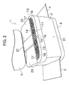
- Fig. 2 is a perspective view showing a state in which respective covers are rotated and opened from a state in Fig. 1.
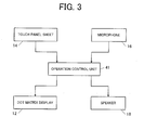
- Fig. 3 is a block diagram showing an electrical configuration for controlling an operating unit.
- Fig. 1 is a perspective view illustrating a general configuration of a copy and facsimile multifunction peripheral according to the embodiment of the present invention
- Fig. 2 is a perspective view illustrating a state in which covers are rotated and opened from a state in Fig. 1
- Fig. 3 is a block diagram illustrating a electrical configuration for controlling an operating unit.
- the copy and facsimile multifunction peripheral 1 as an image forming apparatus and a facsimile apparatus illustrated in Fig. 1 includes a housing 2 of a substantially rectangular parallelepiped shape, a scanner cover (top cover) 3 supported on the top of the housing 2 so as to be capable of opening and closing, a manual feed tray cover (side cover) 4 supported on one side surface of the housing 2 so as to be capable of opening and closing, a paper discharge cover (side cover) 5 supported on the other side surface of the housing 2 so as to be capable of opening and closing.
- an operating unit 11 Provided on the front side of the top of the housing 2 is an operating unit 11 for performing various operations with respect to the copy and facsimile multifunction peripheral 1.
- Fig. 2 illustrates a state in which the scanner cover 3, the manual feed tray cover 4 and the paper discharge cover 5 are opened, respectively.
- the housing 2 is provided with an image reading unit 21 on the upper portion thereof.
- the image reading unit 21 is provided with an original tray 22 on which a read original can be set, and a discharge tray 23 for discharge of the original fed from the original tray 22 with the content being read by a scanner unit (not illustrated).
- the image reading unit 21 is configured to be protected from the outside in a state in which the scanner cover 3 is closed (Fig. 1) when not in use.
- the housing 2 is provided with a paper feed tray 6 on the lower portion thereof, so that a sheet as a recording medium set on the paper feed tray 6 or a sheet set on the manual feed tray cover 4 is fed to an image forming unit 31 in the housing 2.
- the image forming unit 31 is configured to be able to form an image of the content of an original read by the image reading unit 21 or the content that is received through facsimile on a fed sheet and discharge the sheet onto the paper discharge cover 5.
- the operating unit 11 for giving instructions for the operation to the image reading unit 21 and the image forming unit 31 includes a dot matrix display 12 having light-emitting diodes (LEDs) as light-emitting elements arranged in a matrix pattern, a display unit cover 13 provided so as to cover the upper side of the dot matrix display 12, and an operation control unit (touch panel sheet) 14 adhered on a surface (upper surface) of the display unit cover 13.
- a dot matrix display 12 having light-emitting diodes (LEDs) as light-emitting elements arranged in a matrix pattern
- a display unit cover 13 provided so as to cover the upper side of the dot matrix display 12, and an operation control unit (touch panel sheet) 14 adhered on a surface (upper surface) of the display unit cover 13.
- the dot matrix display 12 includes a number of LEDs arranged in rows and columns, and is configured to display predetermined information such as characters and signs by causing these LED group to emit light in predetermined patterns.
- the display unit cover 13 is composed of transparent resin or solid thin film resin, and is configured to allow the user to recognize emitted light from the dot matrix display 12 provided below from above owing to its light-transmitting property. Furthermore, the display unit cover 13 constitutes a part of the contour of the upper surface of the housing 2 and, in the state in which the scanner cover 3 is closed as in Fig. 1, the scanner cover 3 and the display unit cover 13 form a flat contour having no level difference.
- the touch panel sheet 14 is adhered to the surface of the display unit cover 13 so as to cover substantially the entire part of the display area of the dot matrix display 12. With respect to the adhered portion, the display unit cover 13 is formed with a recess having a thickness corresponding to the thickness of the touch panel sheet 14 on the surface thereof, and the touch panel sheet 14 is attached to the recess. Consequently, generation of level difference between the surface of the touch panel sheet 14 and the surface of the display unit cover 13 is prevented. As the touch panel sheet 14 is transparent, the light-emitting display on the dot matrix display 12 can be recognized from above the touch panel sheet 14.
- the display unit cover 13 is formed with microphone holes 15 extending therethrough on the front side of the apparatus with respect to the touch panel sheet 14.
- a microphone 16 for voice input is provided in the housing 2 at a position corresponding to the microphone holes 15.
- the display unit cover 13 is formed with speaker holes 17 extending therethrough on both left and right sides of the touch panel sheet 14. Speakers 18 for voice output are provided in the housing 2 at positions corresponding to the speaker holes 17.
- the operating unit 11 includes an operation control unit 41 for controlling the respective units.
- the operation control unit 41 is configured as a known microcomputer and includes a CPU as computing means, and a ROM and a RAM as storage means.
- the touch panel sheet 14 is connected to the operation control unit 41, and is configured to be able to transmit whether the touch panel sheet 14 is touched or not, or information on the touched position, to the operation control unit 41.
- the microphone 16 is also connected to the operation control unit 41, so that entered voice signals are transmitted to the operation control unit 41.
- the operation control unit 41 is connected to the dot matrix display 12, and is configured to control the light-emitting pattern of the dot matrix display 12.
- the operation control unit 41 is connected to the speakers 18, and is configured to control the voice output from the speakers 18.
- the operation control unit 41 transmits display control signals to the dot matrix display 12, causes specific LEDs of the dot matrix display 12 to emit light, and displays a plurality of predetermined patterns arranged in a row as illustrated in Fig. 1 and Fig. 2. These patterns correspond to various operations such as starting copying operation, setting up the density of copy, starting facsimile transmission, or setting up dial numbers of facsimile destinations.
- the patterns displayed on the dot matrix display 12 are arbitrary, and may be displayed in various patterns such as small drawings (icons), characters, signs, and those similar to operation buttons.
- the touch panel sheet 14 senses the touch, and transmits information on the position touched by the finger (touched position) to the operation control unit 41.
- the operation control unit 41 recognizes the pattern corresponding to the touched position by inspecting which pattern on the dot matrix display 12 includes the touched position on its displayed area. Then, the operation control unit 41 gives an instruction to carry out the operation corresponding to the pattern, to the image reading unit 21, the image forming unit 31 or a facsimile transmission unit(not illustrated), as needed.
- the user is also able to operate the copy and facsimile multifunction peripheral 1 by speaking a predetermined phrase toward the microphone 16 provided on the front surface of the apparatus instead of touching the touch panel sheet 14 with his/her finger.
- the operation control unit 41 recognizes the voice with a known algorithm, so that the fact that the operation that the user intends to do is a registration of dial numbers of destinations of facsimile transmission is determined.
- the operation control unit 41 outputs a guide voice (navigation voice) such as "Please input dial number.” from the speakers 18.
- a guide voice such as "Please input dial number.”
- the user follows the voice, and speaks the dial number toward the microphone 16.
- the operation control unit 41 converts the voice to numerical data through voice input processing, and stores the data as dial information in RAM or the like, which is not illustrated in the drawing.
- the copy and facsimile multifunction peripheral 1 can be voice operated, and hence the operation is further facilitated. It is also possible to select the method of operation adequately according to the content of the operation in such a manner that the voice operation is employed for the operations - such as registration of a dial number - which the user can redo, and the touch operation of the touch panel sheet 14 is employed for the operations - such as the facsimile transmission - which the user cannot redo.
- the voice operation as described above demonstrates a sufficiently effective function in a quiet environment in the room.
- the voice operation cannot be employed easily, for example, when the environment around the copy and facsimile multifunction peripheral 1 is very noisy, or when the environment is not suitable for speaking loudly and clearly.
- the operation control unit 41 displays a specific pattern (a pattern for allowing the user to switch the input mode to the input through the touch panel sheet 14) on the dot matrix display 12 in the mode of the voice input operation using the microphone 16. Then, when the touch panel sheet 14 senses that the user touches the pattern on the display area, the operation control unit 41 stops the voice input operation, displays a pattern with numeric characters such as "1234567890" on the dot matrix display 12, and switches the input mode to the dial number input mode using the touch panel sheet 14, thereby allowing the user to input, for example, the number "4" by touching the pattern of "4" .
- this control various operating methods are provided according to the various environments, and ease of operation of the copy and facsimile multifunction peripheral 1 is improved.
- the copy and facsimile multifunction peripheral 1 in this embodiment is provided with the operating unit 11 on the top of the housing 2 on the front side of the apparatus, and the operation control unit 41 that controls the operation of the copy and facsimile multifunction peripheral 1 according to the operation of the operating unit 11.
- the operating unit 11 includes the dot matrix display 12 composed of the light-emitting diodes, the light-transmissive display unit cover 13 that covers the display area of the dot matrix display 12 and constitutes the contour of the upper surface of the housing 2 on the front side of the apparatus, and the transparent touch panel sheet 14 provided on the surface of the display unit cover 13 so as to cover the display area of the dot matrix display 12.
- the operation control unit 41 controls the apparatus to display the pattern on the dot matrix display 12 and, when the touch panel sheet 14 senses a touch on the pattern display area, carry out the operation corresponding to the touched pattern.
- the operating unit 11 in this embodiment is not provided with a button (key) having a configuration to be pushed in by an operating force of the user.
- the operating unit 11 in this embodiment is provided with the microphone 16 for voice input, and the operation control unit 41 controls the apparatus to recognize a voice entered through the microphone 16 and carries out the operation corresponding to the result of recognition.
- the voice operation of the copy and facsimile multifunction peripheral 1 is achieved, so that the ease of operation is further improved. It is also possible to selectively switch the operation between the operation through the touch on the touch panel sheet 14 and the voice operation through the microphone 16 according to the content of the operation.
- the display unit cover 13 is formed with speaker holes 17 at the sides of the position corresponding to the dot matrix display 12, and the speakers 18 for voice output are provided at positions corresponding to the speaker holes 17.
- the operation control unit 41 outputs guide voice from the speakers 18 in the mode of the voice input operation through the microphone 16.
- the voice operation is further facilitated. Since the voice outputted from the speakers 18 is propagated through the speaker holes 17 formed on the display unit cover 13 to the outside, the user who is operating the copy and facsimile multifunction peripheral 1 can hear the guide voice clearly.
- the operation control unit 41 in this embodiment controls the apparatus to display a predetermined pattern (a pattern for switching the operation to the touch operation through the touch panel sheet 14) on the dot matrix display 12 in the mode of the voice input operation for entering, for example, the dial number, through the microphone 16. Then, when the touch panel sheet 14 senses a touch on the pattern display area, the voice input operation is stopped, and the pattern corresponding to the voice input operation (numeric characters "1234567890" is displayed on the dot matrix display 12 to switch the input operation to the operation through the touch panel sheet 14.
- the mode of operation can be switched easily to the operation through the touch panel sheet 14. Therefore, the apparatus can be operated with flexibility, and the user-friendliness is further improved.
- the position, shape and size of the dot matrix display 12 may be changed as needed.
- the touch panel sheet 14 may be provided so as to cover only a part of the display area of the dot matrix display 12 instead of covering the entire display area of the dot matrix display 12. It is also possible to arrange an electrostatic capacitance displacement meter which functions as a sensor by measuring displacement of the electrostatic capacity instead of the touch panel sheet.
- the microphone 16 may be arranged, for example, in the vicinity of the speaker 18 on one side instead of the center of the display unit cover 13 on the front side of the apparatus. In this case, the microphone holes 15 may be omitted.
- the microphone 16 and the microphone holes 15 may also be arranged on the front surface (front face) of the housing 2 instead of the upper surface of the housing 2.
- the speakers 18 and the speaker holes 17 may be arranged, for example, on the front surface or the side surface of the housing 2.
- the speakers 18 may be controlled to output various sounds such as a guide voice or an alarm buzzer during the operation of the touch panel sheet 14.
- the dot matrix display 12 is controlled so as to display various contents such as the state of the apparatus or navigating phrases for guiding the operation in addition to displaying a pattern for operation by the touch panel sheet 14.
- the configuration of the embodiment illustrated above is not limited to the copy and facsimile multifunction peripheral 1.
- it is also applicable to a copying machine or a printer in which termination of the printing operation, scaling, the number of copies or prints, selection of the sheet tray, and the density of printing can be operated and set on the operating unit.
Landscapes
- Engineering & Computer Science (AREA)
- Microelectronics & Electronic Packaging (AREA)
- Physics & Mathematics (AREA)
- General Physics & Mathematics (AREA)
- Facsimiles In General (AREA)
- Control Or Security For Electrophotography (AREA)
- Accessory Devices And Overall Control Thereof (AREA)
Abstract
Description
- The present invention relates to a configuration of an image forming apparatus for forming images by operating a control panel.
- A copying machine disclosed in
JP-A-2005-122450 - However, in the configuration described above, a number of buttons or keys are arranged on the operating unit. Therefore, the appearance is complicated, and it gives in many cases the user the impression that it is difficult to operate.
- In view of such circumstances, it is an object of the present invention to achieve a simple design of a control unit and to give the user a fresh operation feeling associated with the impression of being easy to operate.
- The problem to be solved by the present invention is as described above, and means for solving the problem and the effect thereof will be described below.
- According to an aspect of the present invention, a configuration of an image forming apparatus having an operating unit on the upper surface of a housing on the front side of the apparatus and an operation control unit for controlling the operation of the apparatus according to operation of the operating unit as illustrated in the following description is provided. In other words, the operating unit includes a dot matrix display composed of light-emitting diodes, a light-transmissive display unit cover that covers a display area of the dot matrix display and constitutes at least a part of the contour of the upper surface of the housing, and a transparent touch panel sheet provided on a surface of the display unit cover so as to cover at least a part of the display area of the dot matrix display. The operation control unit displays patterns on the dot matrix display and, when the touch panel sheet senses a touch on the pattern display area, controls the apparatus to carry out the operation corresponding to the touched pattern.
- In this configuration, instructions for the operation of the apparatus can be given simply by touching the pattern displayed on the display unit cover on the top of the housing by means of the dot matrix display. Since the display unit cover constitutes the contour of the upper surface of the housing, the impression that the operating unit is integrated with the upper surface of the housing is given in appearance. Therefore, a simple, direct, and fresh operating feeling is provided to the user as if he/she gives an operating instruction not via the independent operating unit, but directly to the apparatus itself.
- The image forming apparatus described above is preferably configured in such a manner that the operating unit is not provided with a button having a configuration to be pushed in by the operating force of the user.
- In this configuration, the impression that the operation is complicated and difficult is not given to the user, and a simple and user-friendly operating feeling is realized. Since the button is eliminated, the appearance is simplified by reducing projections and depressions on the operating unit to the maximum, so that the apparatus is downsized with ease.
- The image forming apparatus described above is preferably configured in such a manner that it includes a microphone for voice input. The operation control unit controls the apparatus to recognize a voice entered through the microphone and carry out the operation corresponding to the result of recognition.
- In this configuration, the voice operation of the image forming apparatus is enabled, so that the ease of operation is further improved. It is also possible to selectively switch the operation between the operation through the touch on the touch panel sheet and the voice operation through the microphone according to the content of the operation.
- The image forming apparatus described above is preferably configured in such a manner that the display unit cover is formed with speaker holes at the side(s) of the position corresponding to the dot matrix display. A speaker(s) for voice output is provided at the position corresponding to the speaker holes. The operation control unit outputs guide voice from the speaker in the mode of the voice input operation through the microphone.
- In this configuration, since the user is able to carry out the voice operation by following a guide voice (a navigation voice) from the speaker, the voice operation is further facilitated. Since the voice outputted from the speaker is propagated through the speaker holes formed on the display unit cover to the outside, the user who is operating the image forming apparatus can hear the guide voice clearly.
- The image forming apparatus is preferably configured in such a manner that the operation control unit displays a predetermined pattern on the dot matrix display in the mode of the voice input operation through the microphone. When the touch panel sheet senses the touch on the pattern display area, the voice input operation is stopped, and the pattern corresponding to the voice input operation is displayed on the dot matrix display to switch the input operation to the operation through the touch panel sheet.
- In this configuration, in a circumstance in which the voice operation is difficult due to the noise in the environment, the mode of operation can be switched easily to the operation through the touch panel sheet. Therefore, the apparatus can be operated with flexibility, and the user-friendliness is further improved.
- According to another aspect of the present invention, a facsimile apparatus as the image forming apparatus is provided.
- Other features, elements, processes, steps, characteristics, and advantages of the present invention will become more apparent from the following detailed description of preferred embodiments of the present invention with reference to the attached drawings.
- Fig. 1 is a perspective view showing a general configuration of a copy and facsimile multifunction peripheral according to an embodiment of the present invention.
- Fig. 2 is a perspective view showing a state in which respective covers are rotated and opened from a state in Fig. 1.
- Fig. 3 is a block diagram showing an electrical configuration for controlling an operating unit.
- Embodiments of the present invention will be described. Fig. 1 is a perspective view illustrating a general configuration of a copy and facsimile multifunction peripheral according to the embodiment of the present invention; Fig. 2 is a perspective view illustrating a state in which covers are rotated and opened from a state in Fig. 1; and Fig. 3 is a block diagram illustrating a electrical configuration for controlling an operating unit.
- The copy and facsimile multifunction peripheral 1 as an image forming apparatus and a facsimile apparatus illustrated in Fig. 1 includes a
housing 2 of a substantially rectangular parallelepiped shape, a scanner cover (top cover) 3 supported on the top of thehousing 2 so as to be capable of opening and closing, a manual feed tray cover (side cover) 4 supported on one side surface of thehousing 2 so as to be capable of opening and closing, a paper discharge cover (side cover) 5 supported on the other side surface of thehousing 2 so as to be capable of opening and closing. Provided on the front side of the top of thehousing 2 is anoperating unit 11 for performing various operations with respect to the copy and facsimile multifunction peripheral 1. - Fig. 2 illustrates a state in which the
scanner cover 3, the manualfeed tray cover 4 and thepaper discharge cover 5 are opened, respectively. As shown in Fig. 2, thehousing 2 is provided with animage reading unit 21 on the upper portion thereof. Theimage reading unit 21 is provided with anoriginal tray 22 on which a read original can be set, and adischarge tray 23 for discharge of the original fed from theoriginal tray 22 with the content being read by a scanner unit (not illustrated). Theimage reading unit 21 is configured to be protected from the outside in a state in which thescanner cover 3 is closed (Fig. 1) when not in use. - The
housing 2 is provided with apaper feed tray 6 on the lower portion thereof, so that a sheet as a recording medium set on thepaper feed tray 6 or a sheet set on the manualfeed tray cover 4 is fed to animage forming unit 31 in thehousing 2. Theimage forming unit 31 is configured to be able to form an image of the content of an original read by theimage reading unit 21 or the content that is received through facsimile on a fed sheet and discharge the sheet onto thepaper discharge cover 5. - The
operating unit 11 for giving instructions for the operation to theimage reading unit 21 and theimage forming unit 31 includes adot matrix display 12 having light-emitting diodes (LEDs) as light-emitting elements arranged in a matrix pattern, adisplay unit cover 13 provided so as to cover the upper side of thedot matrix display 12, and an operation control unit (touch panel sheet) 14 adhered on a surface (upper surface) of thedisplay unit cover 13. - The
dot matrix display 12 includes a number of LEDs arranged in rows and columns, and is configured to display predetermined information such as characters and signs by causing these LED group to emit light in predetermined patterns. Thedisplay unit cover 13 is composed of transparent resin or solid thin film resin, and is configured to allow the user to recognize emitted light from thedot matrix display 12 provided below from above owing to its light-transmitting property. Furthermore, thedisplay unit cover 13 constitutes a part of the contour of the upper surface of thehousing 2 and, in the state in which thescanner cover 3 is closed as in Fig. 1, thescanner cover 3 and thedisplay unit cover 13 form a flat contour having no level difference. - The
touch panel sheet 14 is adhered to the surface of thedisplay unit cover 13 so as to cover substantially the entire part of the display area of thedot matrix display 12. With respect to the adhered portion, thedisplay unit cover 13 is formed with a recess having a thickness corresponding to the thickness of thetouch panel sheet 14 on the surface thereof, and thetouch panel sheet 14 is attached to the recess. Consequently, generation of level difference between the surface of thetouch panel sheet 14 and the surface of thedisplay unit cover 13 is prevented. As thetouch panel sheet 14 is transparent, the light-emitting display on thedot matrix display 12 can be recognized from above thetouch panel sheet 14. - The
display unit cover 13 is formed withmicrophone holes 15 extending therethrough on the front side of the apparatus with respect to thetouch panel sheet 14. Amicrophone 16 for voice input is provided in thehousing 2 at a position corresponding to themicrophone holes 15. - The
display unit cover 13 is formed withspeaker holes 17 extending therethrough on both left and right sides of thetouch panel sheet 14.Speakers 18 for voice output are provided in thehousing 2 at positions corresponding to thespeaker holes 17. - Referring now to Fig. 3, the electrical configuration of the
operating unit 11 of the copy and facsimile multifunction peripheral 1 will be described. Theoperating unit 11 includes anoperation control unit 41 for controlling the respective units. Theoperation control unit 41 is configured as a known microcomputer and includes a CPU as computing means, and a ROM and a RAM as storage means. - The
touch panel sheet 14 is connected to theoperation control unit 41, and is configured to be able to transmit whether thetouch panel sheet 14 is touched or not, or information on the touched position, to theoperation control unit 41. Themicrophone 16 is also connected to theoperation control unit 41, so that entered voice signals are transmitted to theoperation control unit 41. - The
operation control unit 41 is connected to thedot matrix display 12, and is configured to control the light-emitting pattern of thedot matrix display 12. Theoperation control unit 41 is connected to thespeakers 18, and is configured to control the voice output from thespeakers 18. - In this configuration, the
operation control unit 41 transmits display control signals to thedot matrix display 12, causes specific LEDs of thedot matrix display 12 to emit light, and displays a plurality of predetermined patterns arranged in a row as illustrated in Fig. 1 and Fig. 2. These patterns correspond to various operations such as starting copying operation, setting up the density of copy, starting facsimile transmission, or setting up dial numbers of facsimile destinations. The patterns displayed on thedot matrix display 12 are arbitrary, and may be displayed in various patterns such as small drawings (icons), characters, signs, and those similar to operation buttons. - When a user touches a pattern corresponding to the desired operation with his/her finger, the
touch panel sheet 14 senses the touch, and transmits information on the position touched by the finger (touched position) to theoperation control unit 41. Theoperation control unit 41 recognizes the pattern corresponding to the touched position by inspecting which pattern on thedot matrix display 12 includes the touched position on its displayed area. Then, theoperation control unit 41 gives an instruction to carry out the operation corresponding to the pattern, to theimage reading unit 21, theimage forming unit 31 or a facsimile transmission unit(not illustrated), as needed. - On the other hand, the user is also able to operate the copy and facsimile multifunction peripheral 1 by speaking a predetermined phrase toward the
microphone 16 provided on the front surface of the apparatus instead of touching thetouch panel sheet 14 with his/her finger. For example, when the user says "Dial Number Registration" toward the microphone, theoperation control unit 41 recognizes the voice with a known algorithm, so that the fact that the operation that the user intends to do is a registration of dial numbers of destinations of facsimile transmission is determined. - Then, the
operation control unit 41 outputs a guide voice (navigation voice) such as "Please input dial number." from thespeakers 18. The user follows the voice, and speaks the dial number toward themicrophone 16. Theoperation control unit 41 converts the voice to numerical data through voice input processing, and stores the data as dial information in RAM or the like, which is not illustrated in the drawing. - With the procedure described above, the copy and facsimile multifunction peripheral 1 can be voice operated, and hence the operation is further facilitated. It is also possible to select the method of operation adequately according to the content of the operation in such a manner that the voice operation is employed for the operations - such as registration of a dial number - which the user can redo, and the touch operation of the
touch panel sheet 14 is employed for the operations - such as the facsimile transmission - which the user cannot redo. - The voice operation as described above demonstrates a sufficiently effective function in a quiet environment in the room. However, there are cases where the voice operation cannot be employed easily, for example, when the environment around the copy and facsimile multifunction peripheral 1 is very noisy, or when the environment is not suitable for speaking loudly and clearly.
- In view of such circumstances, in this embodiment, the
operation control unit 41 displays a specific pattern (a pattern for allowing the user to switch the input mode to the input through the touch panel sheet 14) on thedot matrix display 12 in the mode of the voice input operation using themicrophone 16. Then, when thetouch panel sheet 14 senses that the user touches the pattern on the display area, theoperation control unit 41 stops the voice input operation, displays a pattern with numeric characters such as "1234567890" on thedot matrix display 12, and switches the input mode to the dial number input mode using thetouch panel sheet 14, thereby allowing the user to input, for example, the number "4" by touching the pattern of "4" . With this control, various operating methods are provided according to the various environments, and ease of operation of the copy and facsimile multifunction peripheral 1 is improved. - As described above, the copy and facsimile multifunction peripheral 1 in this embodiment is provided with the operating
unit 11 on the top of thehousing 2 on the front side of the apparatus, and theoperation control unit 41 that controls the operation of the copy and facsimile multifunction peripheral 1 according to the operation of the operatingunit 11. The operatingunit 11 includes thedot matrix display 12 composed of the light-emitting diodes, the light-transmissive display unit cover 13 that covers the display area of thedot matrix display 12 and constitutes the contour of the upper surface of thehousing 2 on the front side of the apparatus, and the transparenttouch panel sheet 14 provided on the surface of the display unit cover 13 so as to cover the display area of thedot matrix display 12. Theoperation control unit 41 controls the apparatus to display the pattern on thedot matrix display 12 and, when thetouch panel sheet 14 senses a touch on the pattern display area, carry out the operation corresponding to the touched pattern. - Accordingly, instructions for the operation of the apparatus are given to the apparatus easily by touching a pattern displayed on the display unit cover 13 on the top of the
housing 2 by thedot matrix display 12 with a finger. Since thedisplay unit cover 13 constitutes the contour of the upper surface of thehousing 2, the impression that the operatingunit 11 is integrated in the upper surface of thehousing 2 is given in appearance. Therefore, a simple, direct, and fresh operating feeling is provided to the user as if he/she gives the operating instruction not via the independent operating unit, but directly to the apparatus itself. - The operating
unit 11 in this embodiment is not provided with a button (key) having a configuration to be pushed in by an operating force of the user. - In this configuration, the impression that the operation is complicated and difficult is not given to the user, and a simple and user-friendly operating feeling is realized. Since the button (key) is eliminated, the appearance is simplified by reducing projections and depressions on the operating
unit 11 to the maximum, so that the apparatus is downsized with ease. - The operating
unit 11 in this embodiment is provided with themicrophone 16 for voice input, and theoperation control unit 41 controls the apparatus to recognize a voice entered through themicrophone 16 and carries out the operation corresponding to the result of recognition. - In this configuration, the voice operation of the copy and facsimile multifunction peripheral 1 is achieved, so that the ease of operation is further improved. It is also possible to selectively switch the operation between the operation through the touch on the
touch panel sheet 14 and the voice operation through themicrophone 16 according to the content of the operation. - In this embodiment, the
display unit cover 13 is formed with speaker holes 17 at the sides of the position corresponding to thedot matrix display 12, and thespeakers 18 for voice output are provided at positions corresponding to the speaker holes 17. Theoperation control unit 41 outputs guide voice from thespeakers 18 in the mode of the voice input operation through themicrophone 16. - Accordingly, since the user is able to carry out the voice operation by following a guide voice from the
speakers 18, the voice operation is further facilitated. Since the voice outputted from thespeakers 18 is propagated through the speaker holes 17 formed on the display unit cover 13 to the outside, the user who is operating the copy and facsimile multifunction peripheral 1 can hear the guide voice clearly. - The
operation control unit 41 in this embodiment controls the apparatus to display a predetermined pattern (a pattern for switching the operation to the touch operation through the touch panel sheet 14) on thedot matrix display 12 in the mode of the voice input operation for entering, for example, the dial number, through themicrophone 16. Then, when thetouch panel sheet 14 senses a touch on the pattern display area, the voice input operation is stopped, and the pattern corresponding to the voice input operation (numeric characters "1234567890") is displayed on thedot matrix display 12 to switch the input operation to the operation through thetouch panel sheet 14. - Accordingly, in a circumstance in which the voice operation is difficult due to the noise in the environment, the mode of operation can be switched easily to the operation through the
touch panel sheet 14. Therefore, the apparatus can be operated with flexibility, and the user-friendliness is further improved. - The embodiment of the invention has been described thus far, the configuration illustrated above may be modified, for example, as follows.
- The position, shape and size of the
dot matrix display 12 may be changed as needed. Thetouch panel sheet 14 may be provided so as to cover only a part of the display area of thedot matrix display 12 instead of covering the entire display area of thedot matrix display 12. It is also possible to arrange an electrostatic capacitance displacement meter which functions as a sensor by measuring displacement of the electrostatic capacity instead of the touch panel sheet. - The
microphone 16 may be arranged, for example, in the vicinity of thespeaker 18 on one side instead of the center of the display unit cover 13 on the front side of the apparatus. In this case, the microphone holes 15 may be omitted. Themicrophone 16 and the microphone holes 15 may also be arranged on the front surface (front face) of thehousing 2 instead of the upper surface of thehousing 2. Thespeakers 18 and the speaker holes 17 may be arranged, for example, on the front surface or the side surface of thehousing 2. - The
speakers 18 may be controlled to output various sounds such as a guide voice or an alarm buzzer during the operation of thetouch panel sheet 14. Thedot matrix display 12 is controlled so as to display various contents such as the state of the apparatus or navigating phrases for guiding the operation in addition to displaying a pattern for operation by thetouch panel sheet 14. - The configuration of the embodiment illustrated above is not limited to the copy and facsimile multifunction peripheral 1. For example, it is also applicable to a copying machine or a printer in which termination of the printing operation, scaling, the number of copies or prints, selection of the sheet tray, and the density of printing can be operated and set on the operating unit.
- While the present invention has been described with respect to preferred embodiments thereof, it will be apparent to those skilled in the art that the disclosed invention may be modified in numerous ways and may assume many embodiments other than those specifically set out and described above. Accordingly, it is intended by the appended claims to cover all modifications of the present invention that fall within the true scope of the present invention.
Claims (11)
- An image forming apparatus having an operating unit (11) on the upper surface of a housing on the front side of the apparatus and an operation control unit (41) for controlling the operation of the apparatus according to the operation of the operating unit (11),
wherein the operating unit includes:a dot matrix display (12) including a light-emitting element;a light-transmissive display unit cover (13) that covers a display area of the dot matrix display and constitutes at least a part of the contour of the upper surface of the housing; andan operation input unit (14) provided on the surface of the display unit cover so as to cover at least a part of the display area of the dot matrix display, andwherein the operation control unit displays patterns on the dot matrix display and, when the operation input unit senses a touch on the pattern display area, controls the apparatus to carry out the operation corresponding to the touched pattern. - An image forming apparatus according to claim 1, wherein the light-emitting element is a light-emitting diode.
- An image forming apparatus according to claim 1 or 2, wherein the operation input unit is a transparent touch panel sheet.
- An image forming apparatus according to any preceding claim, wherein the operating unit is not provided with any button having a configuration to be pushed in by an operating force of a user.
- An image forming apparatus according to any preceding claim, wherein the display unit cover is formed of transparent resin.
- An image forming apparatus according to any of claims 1 to 4, wherein the display unit cover is formed of solid thin film resin.
- An image forming apparatus according to any preceding claim, comprising a microphone (16) for voice input,
wherein the operation control unit recognizes a voice entered through the microphone and controls the apparatus to carry out an operation corresponding to the result of recognition. - An image forming apparatus according to claim 7, comprising:speaker holes (17) formed on the display unit cover; anda speaker (18) for voice output provided at a position corresponding to the speaker holes;wherein the operation control unit outputs a guide voice from the speaker in the mode of voice input operation by means of the microphone.
- An image forming apparatus according to claim 8, wherein the speaker holes are formed through the display unit cover at positions on both left and right sides of the touch panel sheet.
- An image forming apparatus according to any of claims 7 to 9, wherein the operation control unit displays a predetermined pattern on the dot matrix display unit in the mode of voice input operation by means of the microphone and, when the operation input unit senses a touch on the pattern display area, stops the voice input operation and displays a pattern corresponding to the voice input operation on the dot matrix display to switch the operation to the mode of the operation by the touch panel sheet 14.
- A facsimile apparatus as the image forming apparatus according to any of claims 1 to 10.
Applications Claiming Priority (1)
| Application Number | Priority Date | Filing Date | Title |
|---|---|---|---|
| JP2006310224A JP2008129054A (en) | 2006-11-16 | 2006-11-16 | Image forming apparatus and facsimile apparatus |
Publications (2)
| Publication Number | Publication Date |
|---|---|
| EP1923747A2 true EP1923747A2 (en) | 2008-05-21 |
| EP1923747A3 EP1923747A3 (en) | 2009-10-14 |
Family
ID=38949728
Family Applications (1)
| Application Number | Title | Priority Date | Filing Date |
|---|---|---|---|
| EP07119231A Withdrawn EP1923747A3 (en) | 2006-11-16 | 2007-10-24 | Image Forming Apparatus and Facsimile Apparatus |
Country Status (4)
| Country | Link |
|---|---|
| US (1) | US20080117180A1 (en) |
| EP (1) | EP1923747A3 (en) |
| JP (1) | JP2008129054A (en) |
| CN (1) | CN101183236A (en) |
Families Citing this family (8)
| Publication number | Priority date | Publication date | Assignee | Title |
|---|---|---|---|---|
| JP2012108365A (en) * | 2010-11-18 | 2012-06-07 | Konica Minolta Business Technologies Inc | Image forming apparatus |
| US9904316B2 (en) * | 2014-03-24 | 2018-02-27 | Htc Corporation | Method of controlling a mobile electronic device through a cover, mobile electronic device using the same and storage medium thereof |
| US20150294639A1 (en) * | 2014-04-14 | 2015-10-15 | Sony Corporation | Method and system for switching a mode of an electronic device |
| JP6058614B2 (en) | 2014-10-31 | 2017-01-11 | 京セラドキュメントソリューションズ株式会社 | Image processing apparatus and image processing method |
| CN107786696B (en) * | 2017-12-13 | 2024-06-18 | 京东方科技集团股份有限公司 | Display screen and mobile terminal |
| JP2019176294A (en) * | 2018-03-28 | 2019-10-10 | シャープ株式会社 | Image formation apparatus, control method for image formation apparatus, and control program |
| JP2022015459A (en) * | 2020-07-09 | 2022-01-21 | セイコーエプソン株式会社 | Image forming device and inkjet recording device |
| US20260099635A1 (en) * | 2024-10-09 | 2026-04-09 | Dell Products L.P. | Information handling system secure keyboard with collapsible keys at a numberpad area |
Family Cites Families (14)
| Publication number | Priority date | Publication date | Assignee | Title |
|---|---|---|---|---|
| JPS63231366A (en) * | 1987-03-19 | 1988-09-27 | Toshiba Corp | Composite display and input device |
| CA2061878C (en) * | 1991-02-28 | 2001-06-19 | Takashi Saito | Information processing apparatus |
| JPH06105052A (en) * | 1991-04-05 | 1994-04-15 | Konica Corp | Facsimile equipment |
| US6243682B1 (en) * | 1998-11-09 | 2001-06-05 | Pitney Bowes Inc. | Universal access photocopier |
| JP4000728B2 (en) * | 1999-12-15 | 2007-10-31 | 村田機械株式会社 | Facsimile device |
| JP2002197439A (en) * | 2000-09-22 | 2002-07-12 | Ricoh Co Ltd | Document capture device, document filing system, image processing device, electronic document notarization system, and image processing system |
| US7006249B2 (en) * | 2001-01-18 | 2006-02-28 | Kabushiki Kaisha Toshiba | Image forming system |
| US7515288B2 (en) * | 2001-04-06 | 2009-04-07 | Sharp Kabushiki Kaisha | Image processing apparatus |
| JP2005122450A (en) * | 2003-10-16 | 2005-05-12 | Kyocera Mita Corp | Apparatus provided with display input part |
| JP2005191771A (en) * | 2003-12-25 | 2005-07-14 | Oki Data Corp | Image input apparatus and image processing apparatus |
| JP4324011B2 (en) * | 2004-05-19 | 2009-09-02 | キヤノン株式会社 | Data processing apparatus, image processing apparatus, information notification method thereof, and program |
| TWI264381B (en) * | 2004-11-08 | 2006-10-21 | Benq Corp | Copier |
| JP4659505B2 (en) * | 2005-04-04 | 2011-03-30 | キヤノン株式会社 | Information processing method and apparatus |
| JP4507999B2 (en) * | 2005-06-21 | 2010-07-21 | 富士ゼロックス株式会社 | Printing system, image reading apparatus, and control method thereof |
-
2006
- 2006-11-16 JP JP2006310224A patent/JP2008129054A/en active Pending
-
2007
- 2007-10-24 EP EP07119231A patent/EP1923747A3/en not_active Withdrawn
- 2007-10-25 US US11/923,877 patent/US20080117180A1/en not_active Abandoned
- 2007-11-14 CN CNA2007101659800A patent/CN101183236A/en active Pending
Also Published As
| Publication number | Publication date |
|---|---|
| US20080117180A1 (en) | 2008-05-22 |
| JP2008129054A (en) | 2008-06-05 |
| CN101183236A (en) | 2008-05-21 |
| EP1923747A3 (en) | 2009-10-14 |
Similar Documents
| Publication | Publication Date | Title |
|---|---|---|
| US20080117180A1 (en) | Image forming apparatus and facsimile apparatus | |
| JP5054147B2 (en) | Image reading device | |
| JP5590974B2 (en) | Operating device and image reading device | |
| KR101192279B1 (en) | Integrated Keypad System | |
| JP5065431B2 (en) | Image reading apparatus and operation panel | |
| JP5595128B2 (en) | Operating device and image reading device | |
| US9203404B2 (en) | Image reading apparatus and operation device | |
| JP2006127516A (en) | Reconfigurable lighted keypad | |
| EP0676781B1 (en) | portable electronic device | |
| JPH1091305A (en) | Input device | |
| JP6724818B2 (en) | Touch operation device and image forming apparatus | |
| JP5414845B2 (en) | Operating device and image reading device | |
| JP2008140245A (en) | Input device and image forming apparatus for visually impaired persons | |
| JP5936730B2 (en) | Image reading device | |
| JP4501680B2 (en) | Display device, operation instruction device and method | |
| JP5709970B2 (en) | Image reading device | |
| JP2005122450A (en) | Apparatus provided with display input part | |
| JP5197869B2 (en) | Image reading device | |
| US12289432B2 (en) | Shortcut copying method for multi-function printer and multi-function printer using the same | |
| JP6375968B2 (en) | Input device and image forming apparatus | |
| JP6395757B2 (en) | Image reading device | |
| JP5436705B2 (en) | Image reading device | |
| JP2006030359A (en) | Electronics | |
| JP2008259002A (en) | Image reading device | |
| JP2006155016A (en) | Operation display device and operation display method for the same |
Legal Events
| Date | Code | Title | Description |
|---|---|---|---|
| PUAI | Public reference made under article 153(3) epc to a published international application that has entered the european phase |
Free format text: ORIGINAL CODE: 0009012 |
|
| AK | Designated contracting states |
Kind code of ref document: A2 Designated state(s): AT BE BG CH CY CZ DE DK EE ES FI FR GB GR HU IE IS IT LI LT LU LV MC MT NL PL PT RO SE SI SK TR |
|
| AX | Request for extension of the european patent |
Extension state: AL BA HR MK RS |
|
| PUAL | Search report despatched |
Free format text: ORIGINAL CODE: 0009013 |
|
| AK | Designated contracting states |
Kind code of ref document: A3 Designated state(s): AT BE BG CH CY CZ DE DK EE ES FI FR GB GR HU IE IS IT LI LT LU LV MC MT NL PL PT RO SE SI SK TR |
|
| AX | Request for extension of the european patent |
Extension state: AL BA HR MK RS |
|
| AKX | Designation fees paid | ||
| REG | Reference to a national code |
Ref country code: DE Ref legal event code: 8566 |
|
| STAA | Information on the status of an ep patent application or granted ep patent |
Free format text: STATUS: THE APPLICATION IS DEEMED TO BE WITHDRAWN |
|
| 18D | Application deemed to be withdrawn |
Effective date: 20100415 |