EP1923677A2 - Verfahren und Vorrichtung zur Zeitbereichsreflektometrie - Google Patents
Verfahren und Vorrichtung zur Zeitbereichsreflektometrie Download PDFInfo
- Publication number
- EP1923677A2 EP1923677A2 EP07254471A EP07254471A EP1923677A2 EP 1923677 A2 EP1923677 A2 EP 1923677A2 EP 07254471 A EP07254471 A EP 07254471A EP 07254471 A EP07254471 A EP 07254471A EP 1923677 A2 EP1923677 A2 EP 1923677A2
- Authority
- EP
- European Patent Office
- Prior art keywords
- voltage output
- method further
- pulse
- dsp
- electrical pulses
- Prior art date
- Legal status (The legal status is an assumption and is not a legal conclusion. Google has not performed a legal analysis and makes no representation as to the accuracy of the status listed.)
- Withdrawn
Links
Images


Classifications
-
- G—PHYSICS
- G01—MEASURING; TESTING
- G01F—MEASURING VOLUME, VOLUME FLOW, MASS FLOW OR LIQUID LEVEL; METERING BY VOLUME
- G01F23/00—Indicating or measuring liquid level or level of fluent solid material, e.g. indicating in terms of volume or indicating by means of an alarm
- G01F23/22—Indicating or measuring liquid level or level of fluent solid material, e.g. indicating in terms of volume or indicating by means of an alarm by measuring physical variables, other than linear dimensions, pressure or weight, dependent on the level to be measured, e.g. by difference of heat transfer of steam or water
- G01F23/28—Indicating or measuring liquid level or level of fluent solid material, e.g. indicating in terms of volume or indicating by means of an alarm by measuring physical variables, other than linear dimensions, pressure or weight, dependent on the level to be measured, e.g. by difference of heat transfer of steam or water by measuring the variations of parameters of electromagnetic or acoustic waves applied directly to the liquid or fluent solid material
- G01F23/284—Electromagnetic waves
-
- G—PHYSICS
- G01—MEASURING; TESTING
- G01S—RADIO DIRECTION-FINDING; RADIO NAVIGATION; DETERMINING DISTANCE OR VELOCITY BY USE OF RADIO WAVES; LOCATING OR PRESENCE-DETECTING BY USE OF THE REFLECTION OR RERADIATION OF RADIO WAVES; ANALOGOUS ARRANGEMENTS USING OTHER WAVES
- G01S13/00—Systems using the reflection or reradiation of radio waves, e.g. radar systems; Analogous systems using reflection or reradiation of waves whose nature or wavelength is irrelevant or unspecified
- G01S13/02—Systems using reflection of radio waves, e.g. primary radar systems; Analogous systems
- G01S13/06—Systems determining position data of a target
- G01S13/08—Systems for measuring distance only
- G01S13/10—Systems for measuring distance only using transmission of interrupted, pulse modulated waves
-
- G—PHYSICS
- G01—MEASURING; TESTING
- G01S—RADIO DIRECTION-FINDING; RADIO NAVIGATION; DETERMINING DISTANCE OR VELOCITY BY USE OF RADIO WAVES; LOCATING OR PRESENCE-DETECTING BY USE OF THE REFLECTION OR RERADIATION OF RADIO WAVES; ANALOGOUS ARRANGEMENTS USING OTHER WAVES
- G01S13/00—Systems using the reflection or reradiation of radio waves, e.g. radar systems; Analogous systems using reflection or reradiation of waves whose nature or wavelength is irrelevant or unspecified
- G01S13/88—Radar or analogous systems specially adapted for specific applications
-
- G—PHYSICS
- G01—MEASURING; TESTING
- G01S—RADIO DIRECTION-FINDING; RADIO NAVIGATION; DETERMINING DISTANCE OR VELOCITY BY USE OF RADIO WAVES; LOCATING OR PRESENCE-DETECTING BY USE OF THE REFLECTION OR RERADIATION OF RADIO WAVES; ANALOGOUS ARRANGEMENTS USING OTHER WAVES
- G01S7/00—Details of systems according to groups G01S13/00, G01S15/00, G01S17/00
- G01S7/02—Details of systems according to groups G01S13/00, G01S15/00, G01S17/00 of systems according to group G01S13/00
- G01S7/03—Details of HF subsystems specially adapted therefor, e.g. common to transmitter and receiver
- G01S7/032—Constructional details for solid-state radar subsystems
-
- G—PHYSICS
- G01—MEASURING; TESTING
- G01S—RADIO DIRECTION-FINDING; RADIO NAVIGATION; DETERMINING DISTANCE OR VELOCITY BY USE OF RADIO WAVES; LOCATING OR PRESENCE-DETECTING BY USE OF THE REFLECTION OR RERADIATION OF RADIO WAVES; ANALOGOUS ARRANGEMENTS USING OTHER WAVES
- G01S13/00—Systems using the reflection or reradiation of radio waves, e.g. radar systems; Analogous systems using reflection or reradiation of waves whose nature or wavelength is irrelevant or unspecified
- G01S13/87—Combinations of radar systems, e.g. primary radar and secondary radar
Definitions
- This invention relates to methods and apparatus to detect liquid levels in containers.
- Detecting fluid levels is important for a variety of reasons. Marine and aviation applications require accurate measurements of fuel to ensure sufficient supplies to reach intended destinations. Aviation applications are exceptionally important to monitor the fuel levels in multiple tanks to ensure proper balance of levels to impart the least impact on a plane's aerodynamics, which can be significantly affected by changes in a plane's three-dimensional center of gravity.
- Another important measurement function is to ascertain the presence of, and amount of, any contaminants in fuel to ensure the safe and proper operation of engines operated with the fuel. Entry of contaminants into an operating engine can lead to severe performance problems and even engine failure.
- a means to constantly monitor the presence and amount of contaminants, particularly water, is an essential component of any fuel measurement system.
- An accurate, reliable and safe method of measuring the amount of liquid in a container is essential.
- Applications include fuel tanks containing volatile liquids, although the invention described herein can accommodate a wide range of liquids, regardless of their volatility characteristics.
- Other parameters that must be ascertained with accuracy and consistency are the type of fuel and the contamination content, if any.
- a further consideration is a need for hardware that meets the EMI, ESD and Interface requirements of a container, such as an aviation fuel tank, in its environment in a safe manner.
- Prior radar technology includes methods to scan, lock on and track targets.
- the basic approach is to transmit a signal that scans targets, perform gating on a receiver and select targets to lock onto and track. Analysis of the received signal can then be used to determine the distance (range) of the target and to perform signature recognition to define the type of target and its characteristics.
- Combining radar technology with transmission line theory through a shielded cable solves the problems attendant with sensing liquid levels in containers, particularly those used in the aviation field.
- a coaxial probe (tube) is connected to a power source and circuitry designed to provide time domain reflectometric readings to determine the level of, and presence of, impurities in a liquid.
- a power source also called Micropower Impulse radar, the system involves sending a very low microwave pulse along a waveguide, a probe. At least part of the pulse is reflected at the fluid being measured. The transmitted and reflected pulse times are measured and used as the basis for calculating the fluid's level in a container.
- the coaxial probe connected to the circuitry suitably enables the apparatus to meet all aircraft intrinsic safety requirements such as low electromagnetic interference sensitivity.
- Embodiments of apparatus works exceptionally well in a very noisy environment while creating very little noise out.
- the apparatus can be hermetically sealed and require a very low voltage to operate.
- a closed loop configuration is used to scan, track and lock onto transmitted and reflected pulses.
- the propagation speed of the microwave pulse through a material can be used to ascertain the identity of the material through which the pulse is traveling.
- the propagation speed is directly related to the material's dielectric constant. Materials with different dielectric constants will result in different propagation speeds.
- the apparatus can be used to measure fluid and/or gas contamination.
- the transit time of the pulse can be used to measure the dielectric constant also known as the material's relative permittivity.
- a further aspect of the invention is to employ a digital signal processor (DSP) to substantially reduce signal-to-noise ratio and improve signal clarity with a novel algorithm to scan, lock and track fluid levels in a container.
- DSP digital signal processor
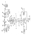
- FIG. 1 is a schematic diagram of the circuitry according to one embodiment of the invention.
- FIG. 2 is a block diagram and flowchart of the DSP integrate and limit algorithms according to one embodiment of the invention.
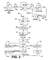
- FIG. 3 is a block diagram and flowchart of DSP algorithms using a low pass/high pass filter according to another embodiment of the invention.
- FIG. 4a is a flow chart of the calculations made to convert reflected signals into measurements of height, weight and temperature of a monitored fluid according to one embodiment of the invention.
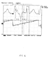
- FIG. 4b shows measured receiver data and results calculated there from according one embodiment of the invention.
- FIG. 5 is shows a series of coaxial probes attached to a central processing unit.
- FIG. 6 is a graphical representation/plot of a recorded pulse showing the presence of air and fuel in a fuel tank half full with fuel.
- FIG. 7 is a graphical representation/plot of a recorded pulse showing the presence of air in an empty fuel tank.
- the diagram illustrates the basic implementation of the analog transmit and receive channels.
- a digital signal processor used to close the scan, lock and track loops and analyze the data is shown.
- the DSP is particularly beneficial in this application as it provides a superior signal-to-noise ratio and enhanced fidelity or image clarity, provides very accurate crystal-based timing and is independent of temperature variations as compared to prior art analog circuitry.
- a square wave pulse from about 1 to about 3 MHz is generated by a clock in the DSP and is buffered by passing through amplifier 12.
- the transmission pulse is delayed by delay 14 to synchronize the transmitter and receiver.
- Delay 14 may be analog or digital and fixes the leading edge of the transmit signal with respect to the receiver being gated.
- the output of delay 14 is inverted at a high speed digital logic gate (inverting amplifier) 16, the output of which is buffered by high speed transistor 17.
- Transistor 17 acts as a switch that turns on when a positive or relatively high voltage, e.g., 3.3 volts, is received and turns off when the voltage is low or ground. In one embodiment, inverter 14 puts out either ground or 3+ volts.
- the output of transistor 17 is converted to a pulse by a capacitor 18 that functions as an open circuit for the slow speed signal or rising edge of the pulse wave, and as a short circuit for the high speed signal or falling edge. In this manner, capacitor 18 prevents passage of the low speed signal.
- Capacitor 18 drives the shielded probe which forms a transmission line driven from the source impedance R7.
- the high speed edge continues along the transmit line into a probe 22, which in one embodiment is shielded, where the source, characteristic and load impedances are optimized to produce large, clearly delineated reflections of various points in a fuel container such as the container bottom (a) and container top (b).
- the propagation time of the wave forms or reflections are directly dependent on the dielectric constant of the material being traversed. For example, the propagation time through air will be faster than through fuel because of the differences between the dielectric constants of air and fuel. Additionally, the propagation time will be affected by the amount of fuel or other fluid in the container. A higher fuel content will lead to a slower return pulse.
- the depth and type of liquid and size of the container dictate the minimum propagation time and what frequency should be used for the transmitter and receiver rates.
- the frequency must allow time for the propagation of the transmit signal to the bottom of the container and return to the receiver.
- the maximum frequency is used thus allowing integration of the maximum number of returns for good signal to noise ratio.
- the 1-3 MHz transmit cycle is constantly repeated in a substantially constant manner.
- the clock output is low pass filtered via resistor 30 and added to the dc signal from amplifier 42 so that the combined signal sets the threshold for comparator 28.
- the amplifier output is inverted similar to the inversion performed by inverter 16 except without the preceding delay.
- the output is buffered by high speed transistor 29 and converted to a pulse by capacitor 26 that couples the high speed falling edge of the waveform to turn a switch 24 on and off.
- Switch 24 may be implemented by either a Fet switch 68 or a diode switch 70. The result is a receiver gate signal synchronized to the transmit pulse but shifted in time depending on the dc signal from amplifier 42.
- a charge pump 23 is incorporated into the system to follow the transmitted and reflected signals.
- the sampling switch is closed for relatively short periods of time ( ⁇ 1 nanosecond) and shifted in picoseconds over about a 200 to about a 500 ms cycle depending on the length of the tube and reflection times. Multiple samples are measured at almost the same time spot to insure a high signal to noise ratio.
- the charge pump includes a capacitor 60 and a resistor 62. Whether the charge pump is charged is dependent on the voltage of the received reflections. If positive voltages are received, the pump is charged.
- the relatively high frequency reflection is converted to a low frequency dc voltage signal that accommodates the limitations of the DSP.
- reducing the frequency rather than having to take measurements in nanoseconds or picoseconds, measurements can be made in milliseconds.
- sampling can be conducted in the same spot relative to the transmit pulse for a relatively long period of time by being shifted (at a picoseconds rate) each time the switch is turned on over this incrementally increasing time differential. Sampling at other spots is accomplished by incrementally increasing the time gap between adjacent switch operation events. DSP 72 initiates the process of setting the time gaps.
- An initial command is sent by receiver gate 75 to an amplifier 42 via an integrate and limit algorithm 90 and a 12 bit pulse width modulator (PWM) 94.
- the dc voltage passes to resistor 36 and a 2 pole low pass filter 37 that includes capacitors 34 and 40 and resistor 38.
- the voltage is then buffered by amplifier 42.
- the output voltage of amplifier 42 passes to a resistor 32 and is summed with the output of resistor 30, the sum of which passes to comparator 28.
- the first command sent results in the initial voltage into resistor 32 being 0 so that there is no time delay effect on the initial signal to switch 24.
- comparator 28 which is inverted, passes to switch 44 and resistor 46. Simultaneously with the exception of the delay produced by delay 14, the transmit line pulse travels to switch 48 and resistor 50.
- the outputs from resistors 46 and 48 are summed and pass through a 2 pole low pass filter 55 that includes capacitors 52 and 56 and resistor 54.
- the filtered dc signal is amplified by amplifier 58 and enters DSP 72 via a 12 bit a/d converter.
- the digitized signal is summed with the command from receiver gate control 75 and processed by the integrate and limit algorithm 90.
- the amplifier 58 dc output represents the time between when the transmit pulse begins and the receiver gate is started. This time is compared to the time commanded by receiver gate control 75. The difference forms the error signal for the scan, lock and track loops. The error is input into the loop compensation (sets the loop bandwidth) shown in FIG. 2 .
- the signal processing begins at start 110.
- a timer 112 controls the operation. If the timer is ready, the a/d conversion begins at 114. If not, the system loops back and tries again until timer 112 is ready.
- the signal from amplifier 58 (represented as v p ) is put through a summation step 116 with the voltage command signal from receiver gate control 75 (represented as V r ).
- the result V in is multiplied by a constant at step 118 and added at step 120 to the immediately preceding voltage output Vout-1 to produce Vout.
- the magnitude of the resulting Vout is checked at step 122 to determine its magnitude. If the magnitude is greater than a preselected limit, the Vout is set to the selected limit at step 126. If the Vout is less than the selected limit, is passes to the PWM 94. Vout also loops back and is delayed at step 124 to be added to the next V in .
- the output of algorithm 90 is used to set the width of the PWM 94 DSP output and controls the time the receiver gate is started (opened) and ended (closed). The loop will drive the error to zero and thus track any or all return propagation times from the transmit time to the bottom of the container.
- the receiver gate controller 75 output begins at zero time (transmit) and increases until the fluid level and the bottom of the tank/container are detected. Once these times are known, the mode can be commanded to change to lock and track the propagation time (distance) with respect to a) the top of the fuel level, b) through the fluid between the top of the fluid and the bottom of the tank, and c) the bottom of the container only.
- the low frequency signals are buffered by amplifier 66 and input to the DSP 72 and into a 12bit a/d converter 73.
- the amount of filtering and amplification can be varied as is known in the art to optimize the tracking analysis.
- the signal is digitized, it is processed through a low pass/high pass filter to shape the signal and remove any noise.
- the filter process begins at start 160.
- a timer 162 controls the operation. If the timer is ready, the a/d conversion begins at 164. If not, the system loops back and tries again until timer 162 is ready. After the conversion, a check is made as to whether the a/d conversion is complete at step 166. If not, the system loops back and continues the conversion.
- the digitized signal represented as Vin is multiplied by a constant K3 at step 170. The result is put through a unit delay at 174 to produce K3 Vin-1. Initially Vin is put through a magnitude check at step 172.
- the Vin is set to the Vmax and exists to pulse shapers 76 and 78 as Vout. If not, if passes to the pulse shapers 76 and 78 as Vout. Vout also loops back and is multiplied by constant K2 at step 176 and put through a unit delay at 178 to become Vout-1. K3Vin is then added to Vout-1 and subtracted from K3 Vin-1. The result is again checked for magnitude at step 172 and passed out as Vout.
- Filters 76 and 78 are used for gain adjustments to keep the returns in a linear region for analysis.
- the filters shape the pulses and pass the shaped pulses to comparators 86 and 88, respectively.
- Hi and low references 80 are put into the comparators.
- a transmit pulse is obtained (+) signal when the transmit pulse is larger than the high reference.
- a bottom tank pulse is obtained when the signal is lower than the low reference.
- the time between the two values is proportional to the amount of fuel in the tank. The more fuel, the larger the time separation will be.
- Algorithm filter 92 (also shown in FIG. 1 ) is used to calculate the propagation time and determine the dielectric constant, the temperature and height and weight of the fluid, which is a function of the fluid. The range of these parameters is then used to determine if any harmful contaminates are present.
- FIGS. 4A shows the calculations necessary to convert the signals into measurements of the height, weight and temperature of the fluid being monitored. Measured receiver data and the results calculated thereof are shown in FIG. 4B .
- a series of TDR fuel probes can be used to monitor fuel levels in one or more fuel tanks found in a conventional aircraft wing.
- two independent systems having a plurality of probes connected to independent power sources and independent fuel quantity indicators are used to monitor fuel levels in separate fuel tanks such as left and right fuel tanks positioned in left and right wings, respectively, of a conventional aircraft.
- FIGS. 6 and 7 plots are shown of readings taken from tanks with the novel coaxial probe system.
- FIG. 6 shows readings taken from a tank half full with fuel.
- the points on the plot representing the air component and fuel or fluid component of the tank are labeled for clarity.
- FIG. 7 is provided to show readings taken from the same tank when essentially empty.
Applications Claiming Priority (2)
| Application Number | Priority Date | Filing Date | Title |
|---|---|---|---|
| US85975606P | 2006-11-17 | 2006-11-17 | |
| US11/650,841 US7650785B1 (en) | 2006-11-17 | 2007-01-08 | Scan lock and track fluid characterization and level sensor apparatus and method |
Publications (2)
| Publication Number | Publication Date |
|---|---|
| EP1923677A2 true EP1923677A2 (de) | 2008-05-21 |
| EP1923677A3 EP1923677A3 (de) | 2009-09-23 |
Family
ID=42229573
Family Applications (1)
| Application Number | Title | Priority Date | Filing Date |
|---|---|---|---|
| EP07254471A Withdrawn EP1923677A3 (de) | 2006-11-17 | 2007-11-15 | Verfahren und Vorrichtung zur Zeitbereichsreflektometrie |
Country Status (3)
| Country | Link |
|---|---|
| US (2) | US7650785B1 (de) |
| EP (1) | EP1923677A3 (de) |
| CA (1) | CA2610510C (de) |
Families Citing this family (7)
| Publication number | Priority date | Publication date | Assignee | Title |
|---|---|---|---|---|
| US8746045B2 (en) * | 2006-11-17 | 2014-06-10 | Meggitt (Orange County), Inc. | System and method for identifying fluids and monitoring fluid quality in a vessel |
| US8281655B2 (en) * | 2009-04-03 | 2012-10-09 | Eaton Corporation | Fuel gauging system utilizing a digital fuel gauging probe |
| WO2011073366A1 (en) * | 2009-12-18 | 2011-06-23 | Total Petrochemicals Research Feluy | Method for monitoring the level of an ethylene polymerization catalyst slurry |
| DE102011082367A1 (de) * | 2011-09-08 | 2013-03-14 | Endress + Hauser Gmbh + Co. Kg | Verfahren zur Füllstandsmessung nach dem Laufzeitprinzip |
| US8935694B2 (en) * | 2012-01-23 | 2015-01-13 | International Business Machines Corporation | System and method for selectively saving and restoring state of branch prediction logic through separate hypervisor-mode and guest-mode and/or user-mode instructions |
| US9081081B2 (en) * | 2012-11-05 | 2015-07-14 | Magnetrol International, Incorporated | Diode switched front end for guided wave radar level transmitter |
| US10379131B2 (en) | 2015-11-18 | 2019-08-13 | Elbit Systems Of America/Kmc Systems, Inc. | Systems and methods for detecting a liquid level |
Citations (2)
| Publication number | Priority date | Publication date | Assignee | Title |
|---|---|---|---|---|
| US5734346A (en) * | 1992-05-23 | 1998-03-31 | Cambridge Consultants Limited | Method of an apparatus for detecting the displacement of a target |
| US20050024259A1 (en) * | 2003-07-30 | 2005-02-03 | Berry James M. | Guided wave radar level transmitter with automatic velocity compensation |
Family Cites Families (28)
| Publication number | Priority date | Publication date | Assignee | Title |
|---|---|---|---|---|
| US3824597A (en) * | 1970-11-09 | 1974-07-16 | Data Transmission Co | Data transmission network |
| CA1214858A (en) * | 1984-09-27 | 1986-12-02 | Stanley Panton | Acoustic ranging system |
| US5160933A (en) * | 1990-08-28 | 1992-11-03 | Honeywell Inc. | Radar altimeter with self-calibration feature |
| US5457990A (en) | 1991-12-03 | 1995-10-17 | Cambridge Consultants Limited | Method and apparatus for determining a fluid level in the vicinity of a transmission line |
| US20050192727A1 (en) | 1994-05-09 | 2005-09-01 | Automotive Technologies International Inc. | Sensor Assemblies |
| US5609059A (en) * | 1994-12-19 | 1997-03-11 | The Regents Of The University Of California | Electronic multi-purpose material level sensor |
| US5610611A (en) | 1994-12-19 | 1997-03-11 | The Regents Of The University Of California | High accuracy electronic material level sensor |
| US5827985A (en) | 1995-12-19 | 1998-10-27 | Endress + Hauser Gmbh + Co. | Sensor apparatus for process measurement |
| US5841666A (en) | 1995-12-21 | 1998-11-24 | Endress + Hauser Gmbh + Co. | Processor apparatus and method for a process measurement signal |
| US6281801B1 (en) | 1997-06-04 | 2001-08-28 | Bechtel Bwxt Idaho, Llc | System and method for monitoring water content or other dielectric influences in a medium |
| US5943908A (en) | 1997-09-08 | 1999-08-31 | Teleflex Incorporated | Probe for sensing fluid level |
| US5943003A (en) * | 1997-11-18 | 1999-08-24 | Raytheon Company | Radar system |
| US6078280A (en) | 1998-01-09 | 2000-06-20 | Endress + Hauser Gmbh + Co. | Periodic probe mapping |
| US5973637A (en) | 1998-01-09 | 1999-10-26 | Endress + Hauser Gmbh + Co. | Partial probe mapping |
| US6069581A (en) * | 1998-02-20 | 2000-05-30 | Amerigon | High performance vehicle radar system |
| US6626038B1 (en) * | 1998-06-18 | 2003-09-30 | Magnetrol International Inc. | Time domain reflectometry measurement instrument |
| US6559657B1 (en) | 1999-01-13 | 2003-05-06 | Endress+Hauser Gmbh+Co. | Probe mapping diagnostic methods |
| US6644114B1 (en) * | 1999-12-30 | 2003-11-11 | Mcewan Technologies, Llc | Direct PWM reflectometer |
| US6690320B2 (en) * | 2000-06-13 | 2004-02-10 | Magnetrol International Incorporated | Time domain reflectometry measurement instrument |
| US6650280B2 (en) | 2000-12-08 | 2003-11-18 | The United States Of America As Represented By The Administrator Of The National Aeronautics And Space Administration | Measurement system and method |
| US6556511B1 (en) * | 2001-11-01 | 2003-04-29 | Techno Research | Method of locking onto and tracking a target |
| US6993967B2 (en) | 2002-07-12 | 2006-02-07 | Ti Group Automotive Systems, L.L.C. | Fluid level sensor |
| US7068051B2 (en) | 2003-02-19 | 2006-06-27 | Technical Development Consultants, Inc. | Permittivity monitor uses ultra wide band transmission |
| JP4689617B2 (ja) | 2003-10-15 | 2011-05-25 | アクセンサー エービー | 流体面高さ測定装置 |
| US7162922B2 (en) | 2003-12-23 | 2007-01-16 | Freger David I | Non-invasive method for detecting and measuring filling material in vessels |
| US7489745B2 (en) | 2005-10-11 | 2009-02-10 | L-3 Communications Integrated Systems L.P. | Reconfigurable direct RF bandpass sampling receiver and related methods |
| US7446695B2 (en) * | 2006-08-22 | 2008-11-04 | Mcewan Thomas Edward | Precision pulse detection system for radar sensors |
| CA2701375C (en) * | 2007-10-01 | 2015-11-24 | Vibro-Meter, Inc. | System and method for accurately measuring fluid level in a vessel |
-
2007
- 2007-01-08 US US11/650,841 patent/US7650785B1/en active Active
- 2007-11-14 CA CA2610510A patent/CA2610510C/en active Active
- 2007-11-15 EP EP07254471A patent/EP1923677A3/de not_active Withdrawn
-
2009
- 2009-12-03 US US12/630,225 patent/US8020438B2/en active Active
Patent Citations (2)
| Publication number | Priority date | Publication date | Assignee | Title |
|---|---|---|---|---|
| US5734346A (en) * | 1992-05-23 | 1998-03-31 | Cambridge Consultants Limited | Method of an apparatus for detecting the displacement of a target |
| US20050024259A1 (en) * | 2003-07-30 | 2005-02-03 | Berry James M. | Guided wave radar level transmitter with automatic velocity compensation |
Also Published As
| Publication number | Publication date |
|---|---|
| US7650785B1 (en) | 2010-01-26 |
| EP1923677A3 (de) | 2009-09-23 |
| CA2610510A1 (en) | 2008-05-17 |
| CA2610510C (en) | 2013-07-02 |
| US20100139393A1 (en) | 2010-06-10 |
| US8020438B2 (en) | 2011-09-20 |
Similar Documents
| Publication | Publication Date | Title |
|---|---|---|
| US8020438B2 (en) | Scan lock and track fluid characterization and level sensor apparatus and method | |
| EP2198252B1 (de) | System und verfahren zur genauen messung eines fluidstands in einem behälter | |
| US5457990A (en) | Method and apparatus for determining a fluid level in the vicinity of a transmission line | |
| EP0641448B1 (de) | Verfahren und Vorrichtungzur Detektion der Verschiebung eines Ziels | |
| US5898308A (en) | Time-based method and device for determining the dielectric constant of a fluid | |
| US6831594B2 (en) | Guided waver radar level transmitter | |
| CA2270453C (en) | Level measuring device operating with microwave | |
| US9316480B2 (en) | Method of filling level measurement of layered media | |
| US20080048905A1 (en) | Precision pulse detection system for radar sensors | |
| US9121742B2 (en) | Apparatus and method for correcting an offset | |
| EP0807261A2 (de) | Verbesserungen mit bezug auf impulsecho-entfernungsmessung | |
| CA2286439A1 (en) | Improvements in time domain reflectometry | |
| US6023237A (en) | Method and device for measuring the distance between an object and an apparatus for measuring said distance | |
| Grimaldi et al. | Noise-tolerant ultrasonic distance sensor based on a multiple driving approach | |
| JPH04506255A (ja) | 伝送路 | |
| CA2880952C (en) | System and method for accurately measuring fluid level in a vessel | |
| US11193809B2 (en) | Expert control systems and methods for level measurement | |
| UA20804U (en) | Method for determining properties of liquid or free-flowing material | |
| Hardcastle | A high resolution near bed coherent acoustic Doppler current profiler for measurement of turbulent flow | |
| SU972238A1 (ru) | Акустический уровнемер | |
| JPH04147083A (ja) | 超音波式積雪深計用変換器 |
Legal Events
| Date | Code | Title | Description |
|---|---|---|---|
| PUAI | Public reference made under article 153(3) epc to a published international application that has entered the european phase |
Free format text: ORIGINAL CODE: 0009012 |
|
| AK | Designated contracting states |
Kind code of ref document: A2 Designated state(s): AT BE BG CH CY CZ DE DK EE ES FI FR GB GR HU IE IS IT LI LT LU LV MC MT NL PL PT RO SE SI SK TR |
|
| AX | Request for extension of the european patent |
Extension state: AL BA HR MK RS |
|
| REG | Reference to a national code |
Ref country code: HK Ref legal event code: DE Ref document number: 1112638 Country of ref document: HK |
|
| RAP1 | Party data changed (applicant data changed or rights of an application transferred) |
Owner name: VIBRO-METER, INC. |
|
| PUAL | Search report despatched |
Free format text: ORIGINAL CODE: 0009013 |
|
| AK | Designated contracting states |
Kind code of ref document: A3 Designated state(s): AT BE BG CH CY CZ DE DK EE ES FI FR GB GR HU IE IS IT LI LT LU LV MC MT NL PL PT RO SE SI SK TR |
|
| AX | Request for extension of the european patent |
Extension state: AL BA HR MK RS |
|
| 17P | Request for examination filed |
Effective date: 20100128 |
|
| 17Q | First examination report despatched |
Effective date: 20100305 |
|
| AKX | Designation fees paid |
Designated state(s): AT BE BG CH CY CZ DE DK EE ES FI FR GB GR HU IE IS IT LI LT LU LV MC MT NL PL PT RO SE SI SK TR |
|
| RAP1 | Party data changed (applicant data changed or rights of an application transferred) |
Owner name: MEGGITT (NEW HAMPSHIRE), INC. |
|
| RAP1 | Party data changed (applicant data changed or rights of an application transferred) |
Owner name: MEGGITT (ORANGE COUNTY), INC. |
|
| REG | Reference to a national code |
Ref country code: HK Ref legal event code: WD Ref document number: 1112638 Country of ref document: HK |
|
| STAA | Information on the status of an ep patent application or granted ep patent |
Free format text: STATUS: THE APPLICATION IS DEEMED TO BE WITHDRAWN |
|
| 18D | Application deemed to be withdrawn |
Effective date: 20170817 |