EP1923115A1 - Filtereinsatz - Google Patents
Filtereinsatz Download PDFInfo
- Publication number
- EP1923115A1 EP1923115A1 EP07116803A EP07116803A EP1923115A1 EP 1923115 A1 EP1923115 A1 EP 1923115A1 EP 07116803 A EP07116803 A EP 07116803A EP 07116803 A EP07116803 A EP 07116803A EP 1923115 A1 EP1923115 A1 EP 1923115A1
- Authority
- EP
- European Patent Office
- Prior art keywords
- filter
- sealing
- sealing element
- filter insert
- sealing portion
- Prior art date
- Legal status (The legal status is an assumption and is not a legal conclusion. Google has not performed a legal analysis and makes no representation as to the accuracy of the status listed.)
- Granted
Links
Images
Classifications
-
- B—PERFORMING OPERATIONS; TRANSPORTING
- B01—PHYSICAL OR CHEMICAL PROCESSES OR APPARATUS IN GENERAL
- B01D—SEPARATION
- B01D29/00—Filters with filtering elements stationary during filtration, e.g. pressure or suction filters, not covered by groups B01D24/00 - B01D27/00; Filtering elements therefor
- B01D29/01—Filters with filtering elements stationary during filtration, e.g. pressure or suction filters, not covered by groups B01D24/00 - B01D27/00; Filtering elements therefor with flat filtering elements
- B01D29/05—Filters with filtering elements stationary during filtration, e.g. pressure or suction filters, not covered by groups B01D24/00 - B01D27/00; Filtering elements therefor with flat filtering elements supported
- B01D29/07—Filters with filtering elements stationary during filtration, e.g. pressure or suction filters, not covered by groups B01D24/00 - B01D27/00; Filtering elements therefor with flat filtering elements supported with corrugated, folded or wound filtering sheets
-
- B—PERFORMING OPERATIONS; TRANSPORTING
- B01—PHYSICAL OR CHEMICAL PROCESSES OR APPARATUS IN GENERAL
- B01D—SEPARATION
- B01D46/00—Filters or filtering processes specially modified for separating dispersed particles from gases or vapours
- B01D46/0002—Casings; Housings; Frame constructions
- B01D46/0005—Mounting of filtering elements within casings, housings or frames
-
- B—PERFORMING OPERATIONS; TRANSPORTING
- B01—PHYSICAL OR CHEMICAL PROCESSES OR APPARATUS IN GENERAL
- B01D—SEPARATION
- B01D46/00—Filters or filtering processes specially modified for separating dispersed particles from gases or vapours
- B01D46/10—Particle separators, e.g. dust precipitators, using filter plates, sheets or pads having plane surfaces
-
- B—PERFORMING OPERATIONS; TRANSPORTING
- B01—PHYSICAL OR CHEMICAL PROCESSES OR APPARATUS IN GENERAL
- B01D—SEPARATION
- B01D46/00—Filters or filtering processes specially modified for separating dispersed particles from gases or vapours
- B01D46/52—Particle separators, e.g. dust precipitators, using filters embodying folded corrugated or wound sheet material
- B01D46/521—Particle separators, e.g. dust precipitators, using filters embodying folded corrugated or wound sheet material using folded, pleated material
-
- B—PERFORMING OPERATIONS; TRANSPORTING
- B01—PHYSICAL OR CHEMICAL PROCESSES OR APPARATUS IN GENERAL
- B01D—SEPARATION
- B01D2201/00—Details relating to filtering apparatus
- B01D2201/34—Seals or gaskets for filtering elements
-
- B—PERFORMING OPERATIONS; TRANSPORTING
- B01—PHYSICAL OR CHEMICAL PROCESSES OR APPARATUS IN GENERAL
- B01D—SEPARATION
- B01D2271/00—Sealings for filters specially adapted for separating dispersed particles from gases or vapours
- B01D2271/02—Gaskets, sealings
Definitions
- the invention relates to a filter insert, which is preferably used sealingly in a filter housing, with a filter element whose at least one end face is bordered by a reinforcing bracket, on which a sealing element is arranged.
- a filter cartridge which comprises a pleated filter which is insertable into a filter housing.
- the end faces of the pleated filter are bordered by shape-stabilizing, clamp-shaped reinforcing elements, on which a seal is integrally formed, which can be applied under elastic prestressing sealingly against the adjacent housing wall of the filter housing.
- the reinforcing element and the seal are combined to form a common component. Since the reinforcing element and the gasket are made of the same material and must be ensured that the gasket can be placed under elastic prestressing, a relatively soft and resilient material must be selected, otherwise the required sealing properties can not be realized.
- the invention has for its object to provide with simple design measures and in a cost effective manner a filter cartridge, which can be used sealingly in a filter housing. According to a further aspect of the invention, it is expedient to accomplish both a radial and an axial seal by simple means.
- a reinforcing clip which encloses the filter element, which is part of the filter insert, on at least one end face.
- a sealing element is arranged, which is designed as independent of the reinforcing bracket, a separate component.
- This sealing element has two outer sealing portions, which are interconnected via a central sealing portion which is fixed to a wall of the reinforcing bracket.
- the outer sealing portions of the reinforcing bracket are movably held on the central sealing portion, they can relative to the central sealing portion perform a relative movement.
- one of the outer sealing sections extends beyond the axial end face of the reinforcing clip and the second outer sealing section is laterally located on a wall of the reinforcing clip, which permits sealing both on the front side, ie in the axial direction, and in the radial direction ,
- the sealing element expediently extends over the entire length of the reinforcing bracket.
- a U-shaped component is advantageously used, which embraces an end face of the filter element, wherein a filter element made of fleece or paper or a paper-like material made of natural or artificial material is expediently used as the filter element.
- a filter element made of fleece or paper or a paper-like material made of natural or artificial material is expediently used as the filter element.
- Such filter elements are used in particular in air filters, for example for internal combustion engines, or in liquid filters, for example for oil or fuel use.
- the reinforcing bracket and the sealing element can be made of different materials, which are best suited for the particular application of the component in question.
- the sealing element is designed for example as foam strips.
- a predetermined bending point can be introduced into the sealing body in the transition between these two sections, which ensures a defined bending behavior with sealing loading of the outer sealing portion.
- This predetermined bending point is formed for example as a tapered wall portion in the sealing body or has an impression, which facilitates the bend.
- the sealing member may be molded with the central sealing portion either to a wall of the reinforcing bracket or the sealing member is glued to the central sealing portion of the wall of the reinforcing bracket. Both versions can be realized with simple measures and ensure a sufficiently secure connection between reinforcement clamp and sealing element. However, other types of connection, such as mechanical connections such as pinching, screwing or the like come into consideration.
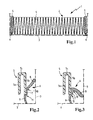
- Fig. 1 shows a section through a filter insert which is sealingly inserted into a filter housing, with frontally arranged reinforcing elements which surround the end fold of the filter element designed as a folded filter element of the filter insert, wherein on the outer wall of the reinforcing clamp, a sealing element is arranged, via which a flow-tight connection between the filter cartridge and the enclosing filter housing,
- FIG. 2 shows a reinforcing clip in section in an enlarged view, including the sealing element, which consists of a central sealing portion, via which the sealing element is connected to the reinforcing bracket, and two outer sealing portions, which are relatively movable relative to the central sealing portion,
- Fig. 3 is a Fig. 2 corresponding representation, with the lateral, outer sealing portion of the sealing element in an angled position.
- the filter shown in Fig. 1 - a gas filter, in particular air filter, or liquid filter such as oil or fuel filter - comprises a filter cartridge 2, which is sealingly inserted into a filter housing 3 of the filter.
- the Filter insert 2 consists of a filter element 4, which is designed as a pleated filter, and of reinforcing brackets 5, each encompassing a frontal fold of the pleated filter clinging.
- a sealing element 6 is arranged, via which the tightness between the filter element 2 and the female filter housing 3 is ensured.
- the sealing member 6 is formed as an independent and independent of the reinforcing bracket 5 component, but which is firmly connected to the reinforcing bracket 5, in particular glued or molded.
- the reinforcing clip 5 is U-shaped and comprises two side walls 5a and 5b and a connecting web 5c, whereby a groove is formed in the reinforcing clip 5, which is provided for receiving the end fold of the filter element is.
- the sealing element 6 On the radially outer wall 5b of the reinforcing bracket is the sealing element 6, which is designed in three parts with a central sealing portion 7 and two integral with the central sealing portion, outer sealing portions 8 and 9.
- the central sealing portion 7 is fixedly connected to the outer side of the radially outer side wall 5b, whereas the outer sealing portions 8 and 9 relative to the central sealing portion 7 are designed to be relatively movable, in particular pivotally.
- the first outer sealing portion 8 extends on the side of the side wall 5 b
- the second outer sealing portion 9 extends on the axial end side of this side wall 5b.
- the respective free end faces of the outer sealing portions 8 and 9 arrive in the sealing position, which is identical to the installation position of the filter insert in abutment against the inner walls of the filter housing 3, wherein the lateral outer sealing portion 8 to the corresponding, lateral inner wall of the housing and the axial protruding outer sealing portion 9 rests against the associated axial inner wall of the filter housing.
- the outer sealing sections 8 and 9 are held pivotably relative to the central sealing section 7.
- This pivoting mobility is made possible by the fact that the central sealing portion 7 is connected over its entire reinforcing bracket 5 facing surface with the outside of the side wall 5b of the reinforcing bracket, in particular glued or molded, whereas the outer sealing portions 8 and 9 no direct connection to the reinforcing bracket 5 have.
- the pivoting mobility is supported and improved by the fact that in the transition region between the central sealing portion 7 and the two outer sealing portions 8 and 9 each have a predetermined bending point 10 and 11 is introduced into the sealing body of the sealing element, which produced by a constriction, a tapered portion or the like becomes. This will become a defined Bending behavior of the outer sealing sections achieved in relation to the central sealing portion, whereby even after frequent use, a defined contact of the sealing element is ensured to the filter housing in the sealing position.
Landscapes
- Chemical & Material Sciences (AREA)
- Chemical Kinetics & Catalysis (AREA)
- Filtering Of Dispersed Particles In Gases (AREA)
- Lubrication Details And Ventilation Of Internal Combustion Engines (AREA)
- Retarders (AREA)
- Liquid Crystal Substances (AREA)
Abstract
Description
- Die Erfindung bezieht sich auf einen Filtereinsatz, der vorzugsweise dichtend in ein Filtergehäuse einsetzbar ist, mit einem Filterelement, dessen mindestens eine Stirnseite von einer Verstärkungsklammer eingefasst ist, an welcher ein Dichtungselement angeordnet ist.
- In der
DE 197 57 423 C1 wird ein Filtereinsatz beschrieben, der einen Faltenfilter umfasst, welcher in ein Filtergehäuse einsetzbar ist. Die Stirnseiten des Faltenfilters sind von formstabilisierenden, klammerförmigen Verstärkungselementen eingefasst, an denen einstückig eine Dichtung angeformt ist, die unter elastischer Vorspannung dichtend an die angrenzende Gehäusewand des Filtergehäuses anlegbar ist. Für kostengünstige Herstellung sind das Verstärkungselement und die Dichtung zu einem gemeinsamen Bauteil zusammengefasst. Da das Verstärkungselement und die Dichtung aus dem gleichen Werkstoff bestehen und gewährleistet sein muss, dass die Dichtung unter elastische Vorspannung gesetzt werden kann, muss ein verhältnismäßig weicher und nachgiebiger Werkstoff gewählt werden, andernfalls können die geforderten Dichtungseigenschaften nicht realisiert werden. - Der Erfindung liegt die Aufgabe zugrunde, mit einfachen konstruktiven Maßnahmen und in kostengünstiger Weise einen Filtereinsatz zu schaffen, der dichtend in ein Filtergehäuse einsetzbar ist. Gemäß eines weiteren Aspektes der Erfindung soll zweckmäßig sowohl eine radiale als auch eine axiale Abdichtung mit einfachen Mitteln zu bewerkstelligen sein.
- Diese Aufgabe wird erfindungsgemäß mit den Merkmalen des Anspruches 1 gelöst. Die Unteransprüche geben zweckmäßige Weiterbildungen an.
- An dem erfindungsgemäßen Filtereinsatz ist eine Verstärkungsklammer vorgesehen, die das Filterelement, welches Bestandteil des Filtereinsatzes ist, an zumindest einer Stirnseite einfasst. An der Verstärkungsklammer ist ein Dichtungselement angeordnet, das als von der Verstärkungsklammer unabhängiges, separates Bauteil ausgeführt ist. Dieses Dichtungselement weist zwei äußere Dichtabschnitte auf, die über einen zentralen Dichtabschnitt miteinander verbunden sind, welcher an einer Wandung der Verstärkungsklammer befestigt ist. Die äußeren Dichtabschnitte der Verstärkungsklammer sind dagegen beweglich am zentralen Dichtabschnitt gehalten, sie können gegenüber dem zentralen Dichtabschnitt eine Relativbewegung ausführen. Auf diese Weise ist es möglich, dass die äußeren Dichtabschnitte bei der Überführung von der unbelasteten Ruhestellung in die Dichtposition ihre Relativlage, bezogen auf den zentralen Dichtabschnitt, ändern, ohne dass von dieser Relativbewegung die Verbindung zwischen dem zentralen Dichtabschnitt und dem Wandabschnitt an der Verstärkungsklammer beeinträchtigt ist. Insbesondere sind die Einzelbewegungen der äußeren Dichtabschnitte unabhängig voneinander, so dass jeder äußere Dichtabschnitt ungeachtet der Bewegung des gegenüberliegenden Dichtabschnittes zwischen Ruhestellung und Dichtstellung überführbar ist. Aufgrund der Zugehörigkeit zu einem gemeinsamen Dichtungselement ist trotz der unabhängigen Bewegungsmöglichkeiten eine konstruktive einfache Abdichtung gegeben, die leicht zu montieren ist und an die jeweiligen konstruktiven Gegebenheiten mit geringem Aufwand angepasst werden kann.
- In zweckmäßiger Weiterbildung ist vorgesehen, dass sich einer der äußeren Dichtabschnitte über die axiale Stirnseite der Verstärkungsklammer erstreckt und der zweite äußere Dichtabschnitt sich seitlich an einer Wandung der Verstärkungsklammer befindet, was eine Abdichtung sowohl an der Stirnseite, also in Axialrichtung, als auch in Radialrichtung ermöglicht. Das Dichtungselement erstreckt sich hierbei zweckmäßig über die gesamte Länge der Verstärkungsklammer.
- Als Verstärkungsklammer wird vorteilhaft ein U-förmiges Bauteil eingesetzt, das eine Stirnseite des Filterelementes umklammert, wobei als Filterelement zweckmäßig ein Faltenfilter aus Vlies oder Papier oder einem papierähnlichen Material aus natürlichem oder künstlichem Werkstoff eingesetzt wird. Derartige Filterelemente finden insbesondere in Luftfiltern, beispielsweise für Brennkraftmaschinen, oder auch in Flüssigkeitsfiltern, beispielsweise für Öl oder Kraftstoff Verwendung.
- Aufgrund der Ausführung als separate Bauteile können die Verstärkungsklammer und das Dichtungselement aus unterschiedlichen Werkstoffen gefertigt sein, die für den jeweiligen Verwendungszweck des betreffenden Bauteiles am besten geeignet sind. Das Dichtungselement ist beispielsweise als Schaumstoffstreifen ausgeführt.
- Um die Relativbeweglichkeit zwischen äußerem Dichtabschnitt und zentralem Dichtabschnitt zu verbessern, kann im Übergang zwischen diesen beiden Abschnitten eine Sollbiegestelle in den Dichtkörper eingebracht sein, die ein definiertes Biegeverhalten bei Dichtbelastung des äußeren Dichtabschnittes sicherstellt. Diese Sollbiegestelle ist beispielsweise als verjüngter Wandabschnitt im Dichtkörper ausgebildet oder besitzt eine Einprägung, welche die Umbiegung erleichtert.
- Das Dichtungselement kann mit dem zentralen Dichtabschnitt entweder an eine Wandung der Verstärkungsklammer angespritzt sein oder das Dichtungselement ist mit dem zentralen Dichtabschnitt an die Wandung der Verstärkungsklammer angeklebt. Beide Ausführungen sind mit einfachen Maßnahmen zu realisieren und gewährleisten eine ausreichend sichere Verbindung zwischen Verstärkungsklammer und Dichtungselement. In Betracht kommen aber auch anderweitige Verbindungsarten, beispielsweise mechanische Verbindungen wie Einklemmen, Anschrauben oder dergleichen.
- Weitere Ausführungen und zweckmäßige Weiterbildungen sind den weiteren Ansprüchen, der Figurenbeschreibung und den Zeichnungen zu entnehmen. Es zeigen:
- Fig. 1 einen Schnitt durch einen Filtereinsatz, der dichtend in ein Filtergehäuse eingesetzt ist, mit stirnseitig angeordneten Verstärkungselementen, welche die Stirnfalte des als Faltenfilter ausgebildeten Filterelementes des Filtereinsatzes einfassen, wobei an der Außenwand der Verstärkungsklammer ein Dichtungselement angeordnet ist, über das eine strömungsdichte Verbindung zwischen dem Filtereinsatz und dem umschließenden Filtergehäuse gegeben ist,
- Fig. 2 eine Verstärkungsklammer im Schnitt in vergrößerter Darstellung einschließlich des Dichtungselementes, welches aus einem zentralen Dichtabschnitt besteht, über das das Dichtungselement mit der Verstärkungsklammer verbunden ist, sowie zwei äußeren Dichtabschnitten, die gegenüber dem zentralen Dichtabschnitt relativbeweglich ausgebildet sind,
- Fig. 3 eine Fig. 2 entsprechende Darstellung, mit dem seitlichen, äußeren Dichtabschnitt des Dichtungselementes in einer abgewinkelten Position.
- Der in Fig. 1 dargestellte Filter - ein Gasfilter, insbesondere Luftfilter, oder Flüssigkeitsfilter wie Öl- oder Kraftstofffilter - umfasst einen Filtereinsatz 2, der dichtend in ein Filtergehäuse 3 des Filters eingesetzt ist. Der Filtereinsatz 2 besteht aus einem Filterelement 4, das als Faltenfilter ausgeführt ist, und aus Verstärkungsklammern 5, die jeweils eine stirnseitige Falte des Faltenfilters klammernd umgreifen. An der außen liegenden Wandseite jeder Verstärkungsklammer 5 ist ein Dichtungselement 6 angeordnet, über das die Dichtigkeit zwischen dem Filtereinsatz 2 und dem aufnehmenden Filtergehäuse 3 sichergestellt wird. Das Dichtungselement 6 ist als eigenständiges und von der Verstärkungsklammer 5 unabhängiges Bauteil ausgebildet, das aber fest mit der Verstärkungsklammer 5 verbunden ist, insbesondere angeklebt oder angespritzt ist.
- Wie der vergrößerten Darstellung gemäß Fig. 2 zu entnehmen, ist die Verstärkungsklammer 5 U-förmig ausgebildet und umfasst zwei Seitenwände 5a und 5b sowie einen verbindenden Steg 5c, wodurch eine Nut in der Verstärkungsklammer 5 gebildet ist, die zur Aufnahme der Stirnfalte des Filterelementes vorgesehen ist. An der radial außen liegenden Wand 5b der Verstärkungsklammer befindet sich das Dichtungselement 6, welches dreiteilig mit einem zentralen Dichtabschnitt 7 und zwei einstückig mit dem zentralen Dichtabschnitt ausgebildeten, äußeren Dichtabschnitten 8 und 9 ausgeführt ist. Der zentrale Dichtabschnitt 7 ist fest mit der Außenseite der radial äußeren Seitenwand 5b verbunden, wohingegen die äußeren Dichtabschnitte 8 und 9 gegenüber dem zentralen Dichtabschnitt 7 relativbeweglich ausgebildet sind, insbesondere schwenkbeweglich. Der erste äußere Dichtabschnitt 8 erstreckt sich an der Seite der Seitenwand 5b, der zweite äußere Dichtabschnitt 9 erstreckt sich dagegen an der axialen Stirnseite dieser Seitenwand 5b. Die jeweiligen freien Stirnseiten der äußeren Dichtabschnitte 8 und 9 gelangen in der Dichtposition, die mit der Einbaulage des Filtereinsatzes identisch ist, in Anlage an die Innenwandungen des Filtergehäuses 3, wobei der seitliche äußere Dichtabschnitt 8 an die entsprechende, seitliche Innenwand des Gehäuses und der axial überstehende äußere Dichtabschnitt 9 an der zugeordneten axialen Innenwand des Filtergehäuses anliegt.
- Wie insbesondere einem Vergleich der Fig. 2 und 3 zu entnehmen, sind die äußeren Dichtabschnitte 8 und 9 gegenüber dem zentralen Dichtabschnitt 7 schwenkbeweglich gehalten. Diese Schwenkbeweglichkeit wird zum einen dadurch ermöglicht, dass der zentrale Dichtabschnitt 7 über seine gesamte der Verstärkungsklammer 5 zugewandte Fläche mit der Außenseite der Seitenwand 5b der Verstärkungsklammer verbunden ist, insbesondere verklebt oder angespritzt ist, wohingegen die äußeren Dichtabschnitte 8 und 9 keine unmittelbare Verbindung zur Verstärkungsklammer 5 aufweisen. Zum anderen wird die Schwenkbeweglichkeit dadurch unterstützt und verbessert, dass im Übergangsbereich zwischen zentralem Dichtabschnitt 7 und den beiden äußeren Dichtabschnitten 8 und 9 jeweils eine Sollbiegestelle 10 und 11 in den Dichtkörper des Dichtungselementes eingebracht ist, die durch eine Einschnürung, einen verjüngten Abschnitt oder dergleichen hergestellt wird. Hierdurch wird ein definiertes Biegeverhalten der äußeren Dichtabschnitte in Bezug auf den zentralen Dichtabschnitt erreicht, wodurch auch nach häufigem Einsatz noch eine definierte Anlage des Dichtungselementes an das Filtergehäuse in der Dichtstellung gewährleistet ist.
Claims (9)
- Filtereinsatz, der dichtend in ein Filtergehäuse (3) einsetzbar ist, mit einem Filterelement (4), dessen mindestens eine Stirnseite von einer Verstärkungsklammer (5) eingefasst ist, an der ein Dichtungselement (6) angeordnet ist, dadurch gekennzeichnet, dass die Verstärkungsklammer (5) und das Dichtungselement (6) als separate Bauteile ausgeführt sind und das Dichtungselement (6) mindestens zwei äußere Dichtabschnitte (8, 9) aufweist, die über einen zentralen Dichtabschnitt (7) miteinander verbunden sind, der mit einer Wandung (5b) der Verstärkungsklammer (5) verbunden ist, wobei die äußeren Dichtabschnitte (8, 9) beweglich am zentralen Dichtabschnitt (7) gehalten sind.
- Filtereinsatz nach Anspruch 1, dadurch gekennzeichnet, dass ein äußerer Dichtabschnitt (8) sich seitlich der Wandung (5b) der Verstärkungsklammer (5) befindet.
- Filtereinsatz nach Anspruch 1 oder 2, dadurch gekennzeichnet, dass ein äußerer Dichtabschnitt (9) der Stirnseite der Wandung (5b) der Verstärkungsklammer (5) axial vorgelagert ist.
- Filtereinsatz nach einem der Ansprüche 1 bis 3, dadurch gekennzeichnet, dass in den Übergang zwischen zentralem Dichtabschnitt (7) und mindestens einem äußeren Dichtabschnitt (8, 9) eine Sollbiegestelle (10, 11) in den Dichtkörper des Dichtungselements (6) eingebracht ist.
- Filtereinsatz nach einem der Ansprüche 1 bis 4, dadurch gekennzeichnet, dass das Dichtungselement (6) an die Verstärkungsklammer (5) angespritzt ist.
- Filtereinsatz nach einem der Ansprüche 1 bis 4, dadurch gekennzeichnet, dass das Dichtungselement (6) an die Verstärkungsklammer (5) angeklebt ist.
- Filtereinsatz nach einem der Ansprüche 1 bis 6, dadurch gekennzeichnet, dass das Filterelement (4) als Faltenfilter ausgeführt ist.
- Filtereinsatz nach einem der Ansprüche 1 bis 7, dadurch gekennzeichnet, dass zwei gegenüberliegende Stirnseiten des Filterelements (4) von jeweils einer Verstärkungsklammer (5) mit daran angeordnetem Dichtungselement (6) eingefasst sind.
- Filtereinsatz nach einem der Ansprüche 1 bis 8, dadurch gekennzeichnet, dass das Dichtungselement (6) als Schaumstoffstreifen ausgeführt ist.
Applications Claiming Priority (1)
| Application Number | Priority Date | Filing Date | Title |
|---|---|---|---|
| DE202006017617U DE202006017617U1 (de) | 2006-11-16 | 2006-11-16 | Filtereinsatz |
Publications (2)
| Publication Number | Publication Date |
|---|---|
| EP1923115A1 true EP1923115A1 (de) | 2008-05-21 |
| EP1923115B1 EP1923115B1 (de) | 2010-03-24 |
Family
ID=39106282
Family Applications (1)
| Application Number | Title | Priority Date | Filing Date |
|---|---|---|---|
| EP07116803A Active EP1923115B1 (de) | 2006-11-16 | 2007-09-20 | Filtereinsatz |
Country Status (4)
| Country | Link |
|---|---|
| US (1) | US20080115474A1 (de) |
| EP (1) | EP1923115B1 (de) |
| AT (1) | ATE461739T1 (de) |
| DE (2) | DE202006017617U1 (de) |
Cited By (1)
| Publication number | Priority date | Publication date | Assignee | Title |
|---|---|---|---|---|
| DE102009041113A1 (de) * | 2009-09-15 | 2011-03-24 | Carl Freudenberg Kg | Filteranordnung mit einrastbaren V-Laschen |
Families Citing this family (9)
| Publication number | Priority date | Publication date | Assignee | Title |
|---|---|---|---|---|
| DE202006018187U1 (de) * | 2006-11-29 | 2008-04-10 | Mann + Hummel Gmbh | Filtereinsatz |
| DE202007018076U1 (de) * | 2007-12-21 | 2009-05-07 | Mann+Hummel Gmbh | Filtereinrichtung, insbesondere Flüssigkeitsfilter |
| DE102008027507A1 (de) * | 2008-06-10 | 2009-12-31 | Carl Freudenberg Kg | Filterelement mit einem 2-K-Rahmen |
| DE202008009504U1 (de) * | 2008-07-15 | 2009-12-03 | Mann+Hummel Gmbh | Filterelement und Filtersystem insbesondere für eine Brennkraftmaschine |
| US8163054B1 (en) | 2009-01-23 | 2012-04-24 | Glasfloss Industries, LP | Air filter with internal frame support |
| US9039801B2 (en) * | 2012-05-01 | 2015-05-26 | Camfil Usa, Inc. | Filter holding frame with filter gasket |
| DE102015004336B4 (de) * | 2015-04-09 | 2023-05-04 | Mann+Hummel Gmbh | Filterelement mit Lasche und Filtersystem |
| EP3101244B1 (de) | 2015-06-01 | 2021-04-07 | Mann + Hummel Gmbh | Dichtelement, ringfilterelement, ölabscheider sowie verfahren zum öffnen des filtergehäuses eines ölabscheiders |
| WO2018175950A1 (en) * | 2017-03-24 | 2018-09-27 | Donaldson Company, Inc. | Air filter system, air filter element for use in same, and method for servicing same |
Citations (7)
| Publication number | Priority date | Publication date | Assignee | Title |
|---|---|---|---|---|
| US3397518A (en) * | 1966-07-21 | 1968-08-20 | Gen Motors Corp | Method of sealing the peripheral edge of a flat pleated filter panel and the filter formed thereby |
| DE19548197A1 (de) * | 1995-12-22 | 1997-06-26 | Freudenberg Carl Fa | Verfahren zur Herstellung eines Faltenfiltereinsatzes |
| DE19757423C1 (de) | 1997-12-23 | 1998-11-26 | Freudenberg Carl Fa | Filtereinsatz |
| DE19840146A1 (de) * | 1998-09-03 | 2000-03-09 | Mann & Hummel Filter | Filter, insbesondere für den Einsatz im Zuluftbereich von Innenräumen |
| EP1464372A1 (de) * | 2003-04-02 | 2004-10-06 | Dana Corporation | Filterelemente mit in Spritzgussverfahren hergestellten thermoplastischen Dichtungen sowie Herstellungsverfahren dafür |
| DE20313468U1 (de) | 2003-08-28 | 2004-12-30 | B & S Industrieservice Gmbh | Filtereinsatz zum Einbau in einen Strömungskanal |
| DE102004037468A1 (de) * | 2004-07-30 | 2006-03-23 | Carl Freudenberg Kg | Luftfilter, Luftfilteranordnung und Verwendung eines Luftfilters |
Family Cites Families (8)
| Publication number | Priority date | Publication date | Assignee | Title |
|---|---|---|---|---|
| JP3299622B2 (ja) * | 1994-03-11 | 2002-07-08 | 豊田紡織株式会社 | エアクリーナ装置 |
| DE19718603A1 (de) * | 1996-05-02 | 1997-11-06 | Knecht Filterwerke Gmbh | Endscheibe für ein Ringfilterelement |
| JP3761585B2 (ja) * | 1996-10-24 | 2006-03-29 | スリーエム カンパニー | 流体濾過用フィルタ装置 |
| DE29904204U1 (de) * | 1999-03-09 | 1999-05-12 | Mann & Hummel Filter | Filterelement zur Filtrierung von flüssigen oder gasförmigen Medien |
| DE19935297A1 (de) * | 1999-07-27 | 2001-02-01 | Mahle Filtersysteme Gmbh | Filterkörper eines Fluidfilters, insbesondere Luftfilters |
| US20030177745A1 (en) * | 2002-03-25 | 2003-09-25 | Jauw Tjoen Liang | Filter device securing mechanism for an air cleaner |
| US7300486B1 (en) * | 2003-04-02 | 2007-11-27 | Wix Filtration Corp Llc | Filter elements having injection molded thermoplastic seals and methods of making same |
| US20050229563A1 (en) * | 2004-04-19 | 2005-10-20 | Holzmann Mark V | Filter element |
-
2006
- 2006-11-16 DE DE202006017617U patent/DE202006017617U1/de not_active Expired - Lifetime
-
2007
- 2007-09-20 AT AT07116803T patent/ATE461739T1/de active
- 2007-09-20 DE DE502007003206T patent/DE502007003206D1/de active Active
- 2007-09-20 EP EP07116803A patent/EP1923115B1/de active Active
- 2007-11-14 US US11/940,153 patent/US20080115474A1/en not_active Abandoned
Patent Citations (7)
| Publication number | Priority date | Publication date | Assignee | Title |
|---|---|---|---|---|
| US3397518A (en) * | 1966-07-21 | 1968-08-20 | Gen Motors Corp | Method of sealing the peripheral edge of a flat pleated filter panel and the filter formed thereby |
| DE19548197A1 (de) * | 1995-12-22 | 1997-06-26 | Freudenberg Carl Fa | Verfahren zur Herstellung eines Faltenfiltereinsatzes |
| DE19757423C1 (de) | 1997-12-23 | 1998-11-26 | Freudenberg Carl Fa | Filtereinsatz |
| DE19840146A1 (de) * | 1998-09-03 | 2000-03-09 | Mann & Hummel Filter | Filter, insbesondere für den Einsatz im Zuluftbereich von Innenräumen |
| EP1464372A1 (de) * | 2003-04-02 | 2004-10-06 | Dana Corporation | Filterelemente mit in Spritzgussverfahren hergestellten thermoplastischen Dichtungen sowie Herstellungsverfahren dafür |
| DE20313468U1 (de) | 2003-08-28 | 2004-12-30 | B & S Industrieservice Gmbh | Filtereinsatz zum Einbau in einen Strömungskanal |
| DE102004037468A1 (de) * | 2004-07-30 | 2006-03-23 | Carl Freudenberg Kg | Luftfilter, Luftfilteranordnung und Verwendung eines Luftfilters |
Cited By (1)
| Publication number | Priority date | Publication date | Assignee | Title |
|---|---|---|---|---|
| DE102009041113A1 (de) * | 2009-09-15 | 2011-03-24 | Carl Freudenberg Kg | Filteranordnung mit einrastbaren V-Laschen |
Also Published As
| Publication number | Publication date |
|---|---|
| DE502007003206D1 (de) | 2010-05-06 |
| DE202006017617U1 (de) | 2008-03-27 |
| ATE461739T1 (de) | 2010-04-15 |
| EP1923115B1 (de) | 2010-03-24 |
| US20080115474A1 (en) | 2008-05-22 |
Similar Documents
| Publication | Publication Date | Title |
|---|---|---|
| EP1923115B1 (de) | Filtereinsatz | |
| DE202007018076U1 (de) | Filtereinrichtung, insbesondere Flüssigkeitsfilter | |
| EP1946811A1 (de) | Filterelement | |
| EP2133550A2 (de) | Filterelement mit einem 2-K-Rahmen | |
| DE102010033669A1 (de) | Dichtvorrichtung eines Filtersystems zur Filtrierung von Fluiden | |
| DE102008013207A1 (de) | Schellenfixierung für ein Schlauchende | |
| DE102011089092A1 (de) | Gehäuse insbesondere für eine Kraftfahrzeugklimaanlage | |
| DE202008015078U1 (de) | Luftfiltereinsatz | |
| EP2754880B1 (de) | Filtereinrichtung | |
| EP1896155B1 (de) | Filteranordnung für flüssigkeiten | |
| DE102004034302A1 (de) | Faltenfiltereinsatz | |
| DE102009013988A1 (de) | Spritzwand mit Kupplungsgeberzylinder | |
| EP3457014B1 (de) | Kanalanordnung mit einem flachkanal und einem flachkanalverbinder | |
| EP3226999A1 (de) | Plattenförmiges filterelement sowie filtereinrichtung | |
| DE102012107263B4 (de) | Steckvorrichtung in einem Endbereich einer Leitung und Verfahren zur Herstellung einer Steckvorrichtung | |
| DE102011110194A1 (de) | Ansatzstutzen für Filterschläuche | |
| DE102009012946A1 (de) | Ventileinrichtung | |
| DE102015016237A1 (de) | Filterbalg und Filterelement | |
| DE102009021512A1 (de) | Luftfilter für eine Brennkraftmaschine | |
| DE102008027847A1 (de) | Luftfilter, insbesondere für die Ansaugluft einer Brennkraftmaschine | |
| EP0307971A2 (de) | Kupplungsmuffe zum Verbinden von zwei Rohrleitungsenden | |
| DE102014008702B4 (de) | Filter mit schräger Dichtungsebene | |
| EP2078554B1 (de) | Filtereinrichtung zur Filtration gasförmiger Fluide | |
| DE102007008553B4 (de) | Drehschieber mit einem drehbar gelagerten Schieberglied | |
| EP1890056A1 (de) | Bürstendichtung für eine Strömungsmaschine |
Legal Events
| Date | Code | Title | Description |
|---|---|---|---|
| PUAI | Public reference made under article 153(3) epc to a published international application that has entered the european phase |
Free format text: ORIGINAL CODE: 0009012 |
|
| AK | Designated contracting states |
Kind code of ref document: A1 Designated state(s): AT BE BG CH CY CZ DE DK EE ES FI FR GB GR HU IE IS IT LI LT LU LV MC MT NL PL PT RO SE SI SK TR |
|
| AX | Request for extension of the european patent |
Extension state: AL BA HR MK RS |
|
| 17P | Request for examination filed |
Effective date: 20080805 |
|
| 17Q | First examination report despatched |
Effective date: 20080910 |
|
| AKX | Designation fees paid |
Designated state(s): AT BE BG CH CY CZ DE DK EE ES FI FR GB GR HU IE IS IT LI LT LU LV MC MT NL PL PT RO SE SI SK TR |
|
| GRAP | Despatch of communication of intention to grant a patent |
Free format text: ORIGINAL CODE: EPIDOSNIGR1 |
|
| GRAS | Grant fee paid |
Free format text: ORIGINAL CODE: EPIDOSNIGR3 |
|
| GRAA | (expected) grant |
Free format text: ORIGINAL CODE: 0009210 |
|
| AK | Designated contracting states |
Kind code of ref document: B1 Designated state(s): AT BE BG CH CY CZ DE DK EE ES FI FR GB GR HU IE IS IT LI LT LU LV MC MT NL PL PT RO SE SI SK TR |
|
| REG | Reference to a national code |
Ref country code: GB Ref legal event code: FG4D Free format text: NOT ENGLISH |
|
| REG | Reference to a national code |
Ref country code: CH Ref legal event code: EP |
|
| REG | Reference to a national code |
Ref country code: IE Ref legal event code: FG4D |
|
| REF | Corresponds to: |
Ref document number: 502007003206 Country of ref document: DE Date of ref document: 20100506 Kind code of ref document: P |
|
| REG | Reference to a national code |
Ref country code: NL Ref legal event code: VDEP Effective date: 20100324 |
|
| PG25 | Lapsed in a contracting state [announced via postgrant information from national office to epo] |
Ref country code: LT Free format text: LAPSE BECAUSE OF FAILURE TO SUBMIT A TRANSLATION OF THE DESCRIPTION OR TO PAY THE FEE WITHIN THE PRESCRIBED TIME-LIMIT Effective date: 20100324 |
|
| LTIE | Lt: invalidation of european patent or patent extension |
Effective date: 20100324 |
|
| PG25 | Lapsed in a contracting state [announced via postgrant information from national office to epo] |
Ref country code: LV Free format text: LAPSE BECAUSE OF FAILURE TO SUBMIT A TRANSLATION OF THE DESCRIPTION OR TO PAY THE FEE WITHIN THE PRESCRIBED TIME-LIMIT Effective date: 20100324 Ref country code: FI Free format text: LAPSE BECAUSE OF FAILURE TO SUBMIT A TRANSLATION OF THE DESCRIPTION OR TO PAY THE FEE WITHIN THE PRESCRIBED TIME-LIMIT Effective date: 20100324 Ref country code: PL Free format text: LAPSE BECAUSE OF FAILURE TO SUBMIT A TRANSLATION OF THE DESCRIPTION OR TO PAY THE FEE WITHIN THE PRESCRIBED TIME-LIMIT Effective date: 20100324 Ref country code: SI Free format text: LAPSE BECAUSE OF FAILURE TO SUBMIT A TRANSLATION OF THE DESCRIPTION OR TO PAY THE FEE WITHIN THE PRESCRIBED TIME-LIMIT Effective date: 20100324 |
|
| REG | Reference to a national code |
Ref country code: IE Ref legal event code: FD4D |
|
| PG25 | Lapsed in a contracting state [announced via postgrant information from national office to epo] |
Ref country code: RO Free format text: LAPSE BECAUSE OF FAILURE TO SUBMIT A TRANSLATION OF THE DESCRIPTION OR TO PAY THE FEE WITHIN THE PRESCRIBED TIME-LIMIT Effective date: 20100324 Ref country code: GR Free format text: LAPSE BECAUSE OF FAILURE TO SUBMIT A TRANSLATION OF THE DESCRIPTION OR TO PAY THE FEE WITHIN THE PRESCRIBED TIME-LIMIT Effective date: 20100625 Ref country code: ES Free format text: LAPSE BECAUSE OF FAILURE TO SUBMIT A TRANSLATION OF THE DESCRIPTION OR TO PAY THE FEE WITHIN THE PRESCRIBED TIME-LIMIT Effective date: 20100705 Ref country code: NL Free format text: LAPSE BECAUSE OF FAILURE TO SUBMIT A TRANSLATION OF THE DESCRIPTION OR TO PAY THE FEE WITHIN THE PRESCRIBED TIME-LIMIT Effective date: 20100324 Ref country code: EE Free format text: LAPSE BECAUSE OF FAILURE TO SUBMIT A TRANSLATION OF THE DESCRIPTION OR TO PAY THE FEE WITHIN THE PRESCRIBED TIME-LIMIT Effective date: 20100324 Ref country code: SE Free format text: LAPSE BECAUSE OF FAILURE TO SUBMIT A TRANSLATION OF THE DESCRIPTION OR TO PAY THE FEE WITHIN THE PRESCRIBED TIME-LIMIT Effective date: 20100324 |
|
| PG25 | Lapsed in a contracting state [announced via postgrant information from national office to epo] |
Ref country code: BG Free format text: LAPSE BECAUSE OF FAILURE TO SUBMIT A TRANSLATION OF THE DESCRIPTION OR TO PAY THE FEE WITHIN THE PRESCRIBED TIME-LIMIT Effective date: 20100624 Ref country code: IS Free format text: LAPSE BECAUSE OF FAILURE TO SUBMIT A TRANSLATION OF THE DESCRIPTION OR TO PAY THE FEE WITHIN THE PRESCRIBED TIME-LIMIT Effective date: 20100724 Ref country code: SK Free format text: LAPSE BECAUSE OF FAILURE TO SUBMIT A TRANSLATION OF THE DESCRIPTION OR TO PAY THE FEE WITHIN THE PRESCRIBED TIME-LIMIT Effective date: 20100324 Ref country code: CZ Free format text: LAPSE BECAUSE OF FAILURE TO SUBMIT A TRANSLATION OF THE DESCRIPTION OR TO PAY THE FEE WITHIN THE PRESCRIBED TIME-LIMIT Effective date: 20100324 |
|
| PLBE | No opposition filed within time limit |
Free format text: ORIGINAL CODE: 0009261 |
|
| STAA | Information on the status of an ep patent application or granted ep patent |
Free format text: STATUS: NO OPPOSITION FILED WITHIN TIME LIMIT |
|
| PG25 | Lapsed in a contracting state [announced via postgrant information from national office to epo] |
Ref country code: DK Free format text: LAPSE BECAUSE OF FAILURE TO SUBMIT A TRANSLATION OF THE DESCRIPTION OR TO PAY THE FEE WITHIN THE PRESCRIBED TIME-LIMIT Effective date: 20100324 Ref country code: PT Free format text: LAPSE BECAUSE OF FAILURE TO SUBMIT A TRANSLATION OF THE DESCRIPTION OR TO PAY THE FEE WITHIN THE PRESCRIBED TIME-LIMIT Effective date: 20100726 Ref country code: IE Free format text: LAPSE BECAUSE OF FAILURE TO SUBMIT A TRANSLATION OF THE DESCRIPTION OR TO PAY THE FEE WITHIN THE PRESCRIBED TIME-LIMIT Effective date: 20100324 |
|
| 26N | No opposition filed |
Effective date: 20101228 |
|
| BERE | Be: lapsed |
Owner name: MANN+HUMMEL G.M.B.H. Effective date: 20100930 |
|
| PG25 | Lapsed in a contracting state [announced via postgrant information from national office to epo] |
Ref country code: IT Free format text: LAPSE BECAUSE OF FAILURE TO SUBMIT A TRANSLATION OF THE DESCRIPTION OR TO PAY THE FEE WITHIN THE PRESCRIBED TIME-LIMIT Effective date: 20100324 |
|
| PG25 | Lapsed in a contracting state [announced via postgrant information from national office to epo] |
Ref country code: MC Free format text: LAPSE BECAUSE OF NON-PAYMENT OF DUE FEES Effective date: 20100930 |
|
| PG25 | Lapsed in a contracting state [announced via postgrant information from national office to epo] |
Ref country code: BE Free format text: LAPSE BECAUSE OF NON-PAYMENT OF DUE FEES Effective date: 20100930 |
|
| PG25 | Lapsed in a contracting state [announced via postgrant information from national office to epo] |
Ref country code: MT Free format text: LAPSE BECAUSE OF FAILURE TO SUBMIT A TRANSLATION OF THE DESCRIPTION OR TO PAY THE FEE WITHIN THE PRESCRIBED TIME-LIMIT Effective date: 20100324 |
|
| REG | Reference to a national code |
Ref country code: CH Ref legal event code: PL |
|
| GBPC | Gb: european patent ceased through non-payment of renewal fee |
Effective date: 20110920 |
|
| PG25 | Lapsed in a contracting state [announced via postgrant information from national office to epo] |
Ref country code: CH Free format text: LAPSE BECAUSE OF NON-PAYMENT OF DUE FEES Effective date: 20110930 Ref country code: LI Free format text: LAPSE BECAUSE OF NON-PAYMENT OF DUE FEES Effective date: 20110930 |
|
| PG25 | Lapsed in a contracting state [announced via postgrant information from national office to epo] |
Ref country code: CY Free format text: LAPSE BECAUSE OF FAILURE TO SUBMIT A TRANSLATION OF THE DESCRIPTION OR TO PAY THE FEE WITHIN THE PRESCRIBED TIME-LIMIT Effective date: 20100324 Ref country code: GB Free format text: LAPSE BECAUSE OF NON-PAYMENT OF DUE FEES Effective date: 20110920 |
|
| PG25 | Lapsed in a contracting state [announced via postgrant information from national office to epo] |
Ref country code: HU Free format text: LAPSE BECAUSE OF FAILURE TO SUBMIT A TRANSLATION OF THE DESCRIPTION OR TO PAY THE FEE WITHIN THE PRESCRIBED TIME-LIMIT Effective date: 20100925 Ref country code: LU Free format text: LAPSE BECAUSE OF NON-PAYMENT OF DUE FEES Effective date: 20100920 |
|
| PG25 | Lapsed in a contracting state [announced via postgrant information from national office to epo] |
Ref country code: TR Free format text: LAPSE BECAUSE OF FAILURE TO SUBMIT A TRANSLATION OF THE DESCRIPTION OR TO PAY THE FEE WITHIN THE PRESCRIBED TIME-LIMIT Effective date: 20100324 |
|
| REG | Reference to a national code |
Ref country code: AT Ref legal event code: MM01 Ref document number: 461739 Country of ref document: AT Kind code of ref document: T Effective date: 20120920 |
|
| PG25 | Lapsed in a contracting state [announced via postgrant information from national office to epo] |
Ref country code: AT Free format text: LAPSE BECAUSE OF NON-PAYMENT OF DUE FEES Effective date: 20120920 |
|
| REG | Reference to a national code |
Ref country code: FR Ref legal event code: PLFP Year of fee payment: 10 |
|
| REG | Reference to a national code |
Ref country code: FR Ref legal event code: PLFP Year of fee payment: 11 |
|
| REG | Reference to a national code |
Ref country code: DE Ref legal event code: R081 Ref document number: 502007003206 Country of ref document: DE Owner name: MANN+HUMMEL GMBH, DE Free format text: FORMER OWNER: MANN + HUMMEL GMBH, 71638 LUDWIGSBURG, DE |
|
| REG | Reference to a national code |
Ref country code: FR Ref legal event code: PLFP Year of fee payment: 12 |
|
| PGFP | Annual fee paid to national office [announced via postgrant information from national office to epo] |
Ref country code: FR Payment date: 20190926 Year of fee payment: 13 |
|
| PG25 | Lapsed in a contracting state [announced via postgrant information from national office to epo] |
Ref country code: FR Free format text: LAPSE BECAUSE OF NON-PAYMENT OF DUE FEES Effective date: 20200930 |
|
| PGFP | Annual fee paid to national office [announced via postgrant information from national office to epo] |
Ref country code: DE Payment date: 20250919 Year of fee payment: 19 |