EP1923009A2 - Chirurgisches Greifinstrument - Google Patents
Chirurgisches Greifinstrument Download PDFInfo
- Publication number
- EP1923009A2 EP1923009A2 EP08001902A EP08001902A EP1923009A2 EP 1923009 A2 EP1923009 A2 EP 1923009A2 EP 08001902 A EP08001902 A EP 08001902A EP 08001902 A EP08001902 A EP 08001902A EP 1923009 A2 EP1923009 A2 EP 1923009A2
- Authority
- EP
- European Patent Office
- Prior art keywords
- axis
- jaw members
- instrument according
- longitudinal axis
- grasping instrument
- Prior art date
- Legal status (The legal status is an assumption and is not a legal conclusion. Google has not performed a legal analysis and makes no representation as to the accuracy of the status listed.)
- Withdrawn
Links
Images


Classifications
-
- A—HUMAN NECESSITIES
- A61—MEDICAL OR VETERINARY SCIENCE; HYGIENE
- A61B—DIAGNOSIS; SURGERY; IDENTIFICATION
- A61B17/00—Surgical instruments, devices or methods, e.g. tourniquets
- A61B17/28—Surgical forceps
- A61B17/29—Forceps for use in minimally invasive surgery
-
- A—HUMAN NECESSITIES
- A61—MEDICAL OR VETERINARY SCIENCE; HYGIENE
- A61B—DIAGNOSIS; SURGERY; IDENTIFICATION
- A61B17/00—Surgical instruments, devices or methods, e.g. tourniquets
- A61B17/11—Surgical instruments, devices or methods, e.g. tourniquets for performing anastomosis; Buttons for anastomosis
- A61B17/115—Staplers for performing anastomosis in a single operation
- A61B17/1155—Circular staplers comprising a plurality of staples
-
- A—HUMAN NECESSITIES
- A61—MEDICAL OR VETERINARY SCIENCE; HYGIENE
- A61B—DIAGNOSIS; SURGERY; IDENTIFICATION
- A61B17/00—Surgical instruments, devices or methods, e.g. tourniquets
- A61B17/11—Surgical instruments, devices or methods, e.g. tourniquets for performing anastomosis; Buttons for anastomosis
- A61B2017/1125—Forceps, specially adapted for performing or assisting anastomosis
-
- A—HUMAN NECESSITIES
- A61—MEDICAL OR VETERINARY SCIENCE; HYGIENE
- A61B—DIAGNOSIS; SURGERY; IDENTIFICATION
- A61B17/00—Surgical instruments, devices or methods, e.g. tourniquets
- A61B17/28—Surgical forceps
- A61B17/29—Forceps for use in minimally invasive surgery
- A61B2017/2926—Details of heads or jaws
- A61B2017/2945—Curved jaws
Definitions
- the present invention relates to surgical instruments, and more particularly, to an endoscopic grasping instrument having jaw members advantageously designed to engage and firmly secure a surgical implement at a desired orientation to facilitate manipulation of the implement about the surgical site, and/or mounting of the instrument to other surgical devices, for example, to a surgical stapler.
- Circular anastomosis is the surgical joining of separate hollow body organ sections so that the sections intercommunicate.
- the anastomosis procedure follows surgery in which a diseased or defective section of hollow tissue is removed and the remaining end sections are to be joined.
- the operative tissue is exposed by making at least one extensive tissue incision, in the body cavity wall and folding the cut tissue back to provide access to the surgical site.
- the diseased section of the organ is removed thereby leaving two separate end sections of organ to be thereafter fastened by anastomosis by means of a stapling instrument.
- the stapling instrument drives a circular array of staples through the end sections and simultaneously cores out any overlapping tissue to free the tubular passages.
- the intestinal section in question is removed leaving the first and second intestinal end sections to be joined by anastomosis.
- the stapling instrument having the anvil component operatively coupled thereto, is applied to the operative site.
- Each end of the intestinal sections to be attached is then secured to their respective stapler cartridge and anvil assembly by a well-known purse string stitch to cause the tissue portions to tighten and to remain on the apparatus in position for permanent attachment by the staples.
- the anvil component is manually brought into close proximity to the staple cartridge.
- the instrument is fired and the intestinal sections are attached by circular rows of staples or fasteners.
- the anvil component typically an anvil assembly comprised of an anvil head and a shaft
- the stapling instrument is introduced either surgically or transanally into the first intestinal section without the anvil assembly in place.
- the anvil assembly is subsequently surgically inserted within the second intestinal section.
- Both intestinal sections are then secured respectively to the anvil assembly and stapler cartridge by a drawstring type suture. It is then necessary to grasp and hold the shaft of the anvil assembly in order to properly mount the anvil assembly or component onto or within the cartridge assembly portion of the instrument.
- the instrument is then fired to complete the anastomosis.
- the present disclosure is directed to an endoscopic surgical instrument having jaws which are adapted to provide a secure grip of the shaft of or for an anvil together with enhanced freedom of movement of the surgical instrument within the patients' body without slippage and/or interference with body organs or tissue of the patient, or other obstructions.
- the surgical jaws are suitably disposed to provide improved holding of a cylindrical or rod-like object at a desired orientation in which the longitudinal central axis of the cylindrical or rod-like object is substantially parallel or slightly oblique with respect to the longitudinal central axis of the elongated shaft of the surgical instrument.
- Such a configuration requires less space in the abdominal cavity to grasp and manipulate the instrument.
- the anvil shaft is suitably designed to facilitate mounting of the shaft to the anastomosis instrument.
- the surgical jaws according to the present invention are adapted for use with an endoscopic surgical instrument and are advantageously configured to facilitate grasping of a shaft of or for an anvil assembly of a circular surgical stapling device and manipulation of the anvil assembly about the operative site.
- the present invention is directed to a surgical instrument including a frame or handle member and an elongated shaft member that has a longitudinal axis, and is operatively coupled to the frame or handle member.
- a pair of jaw members are operatively connected to the elongated member, and are adapted for movement between an open position and a closed position. At least one of the pair of jaw members includes a facing surface having a recess therein and arranged about a central recess axis extending at an angle of about 35° or less relative to the longitudinal axis of the elongated member. In use, upon movement of the jaw members to the closed position, the jaw members form a holding groove that engages and firmly secures an elongated implement therein. Each of the jaw members can have a recess formed therein.
- the central recess axis is about 25° relative to the longitudinal axis of the elongated member.
- each jaw member includes a distal gripper portion wherein at least one distal gripper portion of the pair has the recess therethrough.
- Each distal gripper portion extends along an axis ranging from about 55° to about 75° relative to the longitudinal axis of the elongated member.
- the axis of each gripper portion is about 65° relative to the longitudinal axis.
- the endoscopic surgical instrument includes a frame member and an elongate shaft, wherein the elongate shaft has a proximal end operatively coupled to the frame member and a distal end.
- the elongate shaft defines a longitudinal axis.
- the endoscopic surgical instrument further includes an actuation mechanism coupled to the frame and jaw members, and includes a pair of jaw members operatively coupled to the distal end of the elongate shaft, the pair of jaw members being adapted to move between an open and a closed position.
- Each of the pair of jaw members includes a jaw axis and includes a distal gripper portion having a recess therein.
- the recesses are juxtaposed relative to one another for grasping a shaft of or for an anvil therein.
- the recesses define a holding groove having an axis that is oriented at an angle which is about 35° or less relative to the jaw axis.
- the axis of the holding groove is oriented at an angle which is between about 15° to about 35° relative to the jaw axis. More preferably, the axis of the holding groove is oriented at an angle which is about 25° relative to the jaw axis.
- the axis of the holding groove can be parallel to the jaw axis.
- each jaw member of the endoscopic surgical instrument includes a base portion adapted to engage the distal end of the elongated shaft and a distal end portion having a longitudinal axis and that is located between the gripper portion and the base portion.
- the axis of the holding groove is oriented at an angle which is about 35° or less relative to the longitudinal axis of the distal end portion.
- the axis of the holding groove is oriented at an angle which is about 25° relative to the jaw axis.
- the axis of the holding groove can be parallel to the jaw axis.
- each jaw member includes a base portion that has a diametric hole therethrough and about which the pair of jaws pivot and wherein each base portion includes a cam slot formed proximally of the diametric holes, wherein the cam slots cooperate with one another to transform an axial movement of the actuation means into the opening and closing of the pair of jaw members.
- each jaw member includes a base portion and an adjacent intermediate body portion that includes a distal end portion which is parallel to the jaw axis and which is spaced a distance transversely from an axis defined by each base portion.
- distal refers to that portion which is further from the user
- proximal refers to that portion which is closer to the user
- Endoscopic instrument 100 includes a pair of surgical jaw members 102 and 104 operatively coupled to a distal end of an enlongate shaft 105 defining a longitudinal axis, which jaw members 102 and 104 move, here pivot, in response to the operation of controls on or remote from a frame, e.g., the opening and closing of a handle assembly 106.
- Handle assembly 106 includes a pivoting handle 106A and a stationary handle 106B.
- an actuation mechanism here shown as an inner rod 107, reciprocates in the longitudinal direction indicated by arrow "A" within elongate shaft 105 to operate jaw members 102 and 104.
- a proximal end of elongate shaft 105 and a proximal end of inner rod 107 i.e., the actuation means
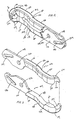
- each jaw member 102 and 104 respectively includes a base portion 108 and 110 at their proximal end, a gripper portion 112 and 114 at their distal end, and an intermediate body portion 116 and 118 interconnecting base portion 108 and 110 to gripper portion 112 and 114, respectively.
- Each base portion 108 and 110 includes a diametric radial hole 120 and 122, respectively for accepting a pivot pin (not shown) therethrough, which pivot pin is secured to surgical instrument 100.
- gripper portions 112 and 114 of jaw members 102 and 104 pivot about the pivot pin passing through radial holes 120 and 122 during an opening and a closing operation.
- Each base portion 108 and 110 is further provided with a cam slot 124 and 126, respectively, which slots are configured and adapted to receive a bearing post 127 ( FIG. 1 ) therethrough.
- cam slots 124 and 126 are formed proximally of radial holes 120 and 122, however, it is envisioned that cam slots 124 and 126 can be formed distally of radial holes 120 and 122.
- bearing post 127 is operatively coupled to handle assembly 106 via the inner rod 107.
- the bearing post translates proximally and distally.
- bearing post 127 slides within cam slots 124 and 126 in order to pivot gripper portions 112 and 114 about pivot pin, thereby opening and closing jaw members 102 and 104.
- handle assembly 106 is actuated closed, the bearing post slides away from jaw members 102 and 104 within cam slots 124 and 126 thereby drawing jaw members 102 and 104 closed.
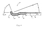
- Each intermediate body portion 116 and 118 of jaw members 102 and 104 includes a proximal end portion 128 and 130 extending substantially axially and distally from base portion 108 and 110, respectively, wherein an axis "A1"of proximal end portions 128 and 130 is in the same plane as an axis "A2" of base portion 108 and 110 (see FIG. 4 ); and a distal end portion 132 and 134 extending substantially axially from an intermediate neck portion 136 and 138, respectively, wherein an axis "B1" of distal end portion 132 and 134 is in a plane spaced a distance "X" from axis "A1, A2" of base portion 108 and 100.
- Intermediate neck portion 136 and 138 interconnects proximal end portions 128 and 130 to distal end portions 132 and 134.
- the axis "A1, A2" is considered to be the axis of the jaw member, i.e., the jaw axis.
- Gripper portions 112 and 114 extend distally from the ends of distal end portions 132 and 134 of jaw members 102 and 104.
- Each gripper portion 112 and 114 is provided with a recess 140, 142, preferably semi-cylindrical formed on corresponding facing surfaces 143.
- recesses 140, 142 form a holding groove "G".
- Holding groove "G” extends through the entire thickness of each gripper portion 112 and 114.
- recesses 140, 142, and holding groove “G” are formed to have a central axis which is orthogonal to the plane of gripper portions 112 and 114.
- gripper portions 112 and 114 are oriented at an angle " ⁇ " that is preferably from about 55° to about 75° relative to the longitudinal axis of elongated shaft 105, rod 107 or to axis "A1" of proximal end portions 128 and 130, axis "A2” of base portions 108 and 110 or axis “B1” of distal end portions 132 and 134. More preferably, angle “ ⁇ " of the plane of gripper portions 112 and 114 is about 70° relative to axes "A1", “A2” or “B1". Most preferably, angle " ⁇ " of the plane of gripper portions 112 and 114 is about 65° relative to axes "A1", “A2” or “B1".
- the central axis of recesses 140, 142 and of holding groove “G” is at an angle " ⁇ " that is preferably from about 15° to about 35°, more preferably about 20° and most preferably about 25° relative to axes "A1", “A2" or "B1".
- each jaw member 102 and 104 can be provided with a gripper portion 112 and 114, at least one, preferably each, having one or more recesses 140 and/or 142, which recess or recesses form(s) a holding groove "G" when the jaw members are in the closed position.
- each recess and holding groove has a central axis that is about 35° or less relative to the longitudinal axis of elongate shaft 105, rod 107 or axis "A1", “A2” or “B1".
- the central axis of recesses 140, 142 and/or of holding groove "G" can be co-axial or co-planar with any one or more of such axes.
- the axis of the shaft can be substantially co-planar with axes "A1", “A2” or “B1” thereby resulting in a substantially co-linear arrangement.
- the central axis of recesses 140, 142 and/or of holding groove "G” can be at an angle " ⁇ " which is 0° or parallel to the longitudinal axis of the elongate shaft.
- holding groove "G" is a substantially circular opening. While a substantially circular opening is preferred, especially for grasping a cylindrical portion of an anvil shaft, it is envisioned that the formed opening can take on any shape, including and not limited to, polygonal, rectangular, triangular, ovular, etc.
- the inner surface of holding grooves 140 and 142 are smooth, however, it is envisioned that the inner surface of holding grooves 140 and 142 can be provided with a textured surface, including but not limited to, knurled, toothed, serrated, etc. The inner surface is designed to allow it to grasp the intended portion, e.g., one or more recesses of or for the anvil shaft.
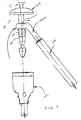
- FIGS. 5 and 6 illustrate one example of the use of the invention in accordance with the present disclosure.
- typical instruments for performing a circular anastomosis of hollow organs include a detachable anvil assembly 200 having a shaft 202 and an attached or detachable anvil head 204, and/or a staple cartridge or cartridge assembly 212 (see FIG. 7 ) to provide circular stapling of the intestinal sections.
- shaft 202 can be detached from an anvil, or can be a trocar shaft.
- anvil assembly 200 is previously inserted into an intestinal section (not shown) with the aid of an insertion instrument "T".
- the open end of the intestinal section is sutured or tied over the anvil head and about an attachment portion of the anvil shaft 202.
- the cartridge assembly 212 (see FIG. 7 ) is previously inserted into the opposite intestinal section (not shown) whose open end is likewise disposed over and sutured about the distal end of the cartridge assembly.
- Shaft 202 may have a recessed grasping portion 206, with a reduced cross section, near a distal end thereof, which, in accordance with the present invention, in FIG. 6 , is to be engaged by recesses 140 and 142 of jaw members 102 and 104.
- the operating surgeon grasps grasping portion 206 of shaft 202 with holding groove "G" of surgical jaw members 102 and 104 while manually or robotically holding or manipulating the frame or handle 14 of, or the endoscopic instrument 10 itself. The surgeon then pulls shaft 202 toward the cartridge assembly for insertion of tip 208 of shaft 202 into a guiding, receiving and engaging portion or the like (not shown) of the cartridge assembly.
- jaw members 102 and 104 are adapted to engage and surround shaft 202 of anvil assembly 200 at various locations and orientations relative thereto.
- jaw members 102 and 104 grasp shaft 202 at a location above or distally of splines 210, e.g., at recess "R" (dashed lines), which splines 210 are used to align shaft 202 with the staple firing mechanism 212 (i.e., cartridge assembly) with anvil assembly 200. In this manner, jaw members 102 and 104 do not interfere with the insertion of shaft 202 into the cartridge assembly 212.
- anvil shaft 202 preferably is adapted to be grasped at a location that is sufficiently removed, for example, more than a third, or half or more than half of the length of shaft 202 measured from the proximal end of the shaft.
- endoscopic surgical instrument 10 is such that instrument 10 can be inserted into the patient via a 15 mm or 10 mm trocar. While an instrument which is insertable through a 15 mm or 10 mm trocar is disclosed, it is envisioned that the instrument can have any size and dimension.
- the present invention provides substantial benefits to users compared to prior art devices.
- the jaws of the invention facilitate grasping and manipulation of an object, such as shaft 202 of anvil assembly 200, toward and mounting it onto or into a targeted structure.
- the surgical instrument of the invention may be used with any other elongated surgical instrument.
- the ease of manipulation provided by the design of the instrument is especially advantageous if there is limited operative space, e.g. if there are certain obstacles limiting the path of movement of the grasping instrument.
- the jaws of the present invention enable the surgeon to approach and grasp the object, e.g., the shaft of or for the anvil, or a trocar, from a substantially longitudinally aligned direction with respect to the surgical instrument that has the jaws.
Applications Claiming Priority (2)
| Application Number | Priority Date | Filing Date | Title |
|---|---|---|---|
| US27352201P | 2001-03-05 | 2001-03-05 | |
| EP02719106A EP1367949B1 (de) | 2001-03-05 | 2002-03-05 | Chirurgische greifvorrichtung |
Related Parent Applications (1)
| Application Number | Title | Priority Date | Filing Date |
|---|---|---|---|
| EP02719106A Division EP1367949B1 (de) | 2001-03-05 | 2002-03-05 | Chirurgische greifvorrichtung |
Publications (2)
| Publication Number | Publication Date |
|---|---|
| EP1923009A2 true EP1923009A2 (de) | 2008-05-21 |
| EP1923009A3 EP1923009A3 (de) | 2009-06-03 |
Family
ID=39313398
Family Applications (1)
| Application Number | Title | Priority Date | Filing Date |
|---|---|---|---|
| EP08001902A Withdrawn EP1923009A3 (de) | 2001-03-05 | 2002-03-05 | Chirurgisches Greifinstrument |
Country Status (1)
| Country | Link |
|---|---|
| EP (1) | EP1923009A3 (de) |
Cited By (4)
| Publication number | Priority date | Publication date | Assignee | Title |
|---|---|---|---|---|
| US8740915B2 (en) | 2010-04-27 | 2014-06-03 | DePuy Synthes Products, LLC | Bone fixation systems and methods of use |
| CN103932750A (zh) * | 2014-05-08 | 2014-07-23 | 黄宇清 | 胸腔镜食管吻合器钉砧把持钳头和具有该钳头的把持钳 |
| EP2774557A1 (de) * | 2013-03-05 | 2014-09-10 | Covidien LP | Ambosszange |
| US8936615B2 (en) | 2010-04-27 | 2015-01-20 | DePuy Synthes Products, LLC | Bone fixation system including K-wire compression |
Citations (6)
| Publication number | Priority date | Publication date | Assignee | Title |
|---|---|---|---|---|
| US4304236A (en) | 1977-05-26 | 1981-12-08 | United States Surgical Corporation | Stapling instrument having an anvil-carrying part of particular geometric shape |
| US4379457A (en) | 1981-02-17 | 1983-04-12 | United States Surgical Corporation | Indicator for surgical stapler |
| US4573468A (en) | 1977-05-26 | 1986-03-04 | United States Surgical Corporation | Hollow body organ stapling instrument and disposable cartridge employing relief vents |
| US4576167A (en) | 1981-09-03 | 1986-03-18 | United States Surgical Corporation | Surgical stapler apparatus with curved shaft |
| US4603693A (en) | 1977-05-26 | 1986-08-05 | United States Surgical Corporation | Instrument for circular surgical stapling of hollow body organs and disposable cartridge therefor |
| WO2001066020A2 (en) | 2000-03-06 | 2001-09-13 | United States Surgical | Apparatus and method for performing a bypass procedure in a digestive system |
Family Cites Families (4)
| Publication number | Priority date | Publication date | Assignee | Title |
|---|---|---|---|---|
| DE4223162C2 (de) * | 1992-07-10 | 1995-09-07 | Ethicon Gmbh | Greifvorrichtung zum Greifen eines chirurgischen Instruments |
| US5354312A (en) * | 1992-09-18 | 1994-10-11 | Ethicon, Inc. | Endoscopic anvil grasping instrument |
| US5443479A (en) * | 1994-02-07 | 1995-08-22 | Bressi, Jr.; Thomas E. | Surgical forceps |
| DE4422621C1 (de) * | 1994-06-28 | 1995-08-31 | Aesculap Ag | Chirurgisches Instrument |
-
2002
- 2002-03-05 EP EP08001902A patent/EP1923009A3/de not_active Withdrawn
Patent Citations (7)
| Publication number | Priority date | Publication date | Assignee | Title |
|---|---|---|---|---|
| US4304236A (en) | 1977-05-26 | 1981-12-08 | United States Surgical Corporation | Stapling instrument having an anvil-carrying part of particular geometric shape |
| US4573468A (en) | 1977-05-26 | 1986-03-04 | United States Surgical Corporation | Hollow body organ stapling instrument and disposable cartridge employing relief vents |
| US4603693A (en) | 1977-05-26 | 1986-08-05 | United States Surgical Corporation | Instrument for circular surgical stapling of hollow body organs and disposable cartridge therefor |
| US4379457A (en) | 1981-02-17 | 1983-04-12 | United States Surgical Corporation | Indicator for surgical stapler |
| US4576167A (en) | 1981-09-03 | 1986-03-18 | United States Surgical Corporation | Surgical stapler apparatus with curved shaft |
| US4646745A (en) | 1981-09-03 | 1987-03-03 | United States Surgical Corporation | Surgical stapler apparatus with curved shaft |
| WO2001066020A2 (en) | 2000-03-06 | 2001-09-13 | United States Surgical | Apparatus and method for performing a bypass procedure in a digestive system |
Cited By (7)
| Publication number | Priority date | Publication date | Assignee | Title |
|---|---|---|---|---|
| US8740915B2 (en) | 2010-04-27 | 2014-06-03 | DePuy Synthes Products, LLC | Bone fixation systems and methods of use |
| US8936615B2 (en) | 2010-04-27 | 2015-01-20 | DePuy Synthes Products, LLC | Bone fixation system including K-wire compression |
| US9113969B2 (en) | 2010-04-27 | 2015-08-25 | DePuy Synthes Products, Inc. | Bone fixation systems and methods of use |
| US9597130B2 (en) | 2010-04-27 | 2017-03-21 | DePuy Synthes Products, Inc. | Bone fixation system including K-wire compression |
| EP2774557A1 (de) * | 2013-03-05 | 2014-09-10 | Covidien LP | Ambosszange |
| US10335178B2 (en) | 2013-03-05 | 2019-07-02 | Covidien Lp | Anvil grasper |
| CN103932750A (zh) * | 2014-05-08 | 2014-07-23 | 黄宇清 | 胸腔镜食管吻合器钉砧把持钳头和具有该钳头的把持钳 |
Also Published As
| Publication number | Publication date |
|---|---|
| EP1923009A3 (de) | 2009-06-03 |
Similar Documents
| Publication | Publication Date | Title |
|---|---|---|
| US7722640B2 (en) | Surgical grasping instrument | |
| AU2002250207A1 (en) | Surgical grasping instrument | |
| US5718360A (en) | Surgical apparatus and detachable anvil rod therefor | |
| US5344059A (en) | Surgical apparatus and anvil delivery system therefor | |
| CA2462536C (en) | Tilt top anvil for a surgical fastener device | |
| US7648514B1 (en) | Deep endoscopic staple and stapler | |
| US8029520B2 (en) | Method for performing trans-anal resection with a curved cutter stapler | |
| AU2002362751A1 (en) | Tilt top anvil for a surgical fastener device | |
| JP2013529981A (ja) | 内視鏡下縫合デバイス、システム及び縫合方法 | |
| JP2009072602A (ja) | アンビル送達デバイスの付属品 | |
| CN111616762A (zh) | 具有可独立移动钳口的外科缝合装置 | |
| EP1923009A2 (de) | Chirurgisches Greifinstrument | |
| US11779342B2 (en) | Laparoscopic purse string suture device | |
| EP3936060A1 (de) | Tabaksbeutelnahtinstrument |
Legal Events
| Date | Code | Title | Description |
|---|---|---|---|
| PUAI | Public reference made under article 153(3) epc to a published international application that has entered the european phase |
Free format text: ORIGINAL CODE: 0009012 |
|
| AC | Divisional application: reference to earlier application |
Ref document number: 1367949 Country of ref document: EP Kind code of ref document: P |
|
| AK | Designated contracting states |
Kind code of ref document: A2 Designated state(s): DE ES FR GB IE IT |
|
| PUAL | Search report despatched |
Free format text: ORIGINAL CODE: 0009013 |
|
| AK | Designated contracting states |
Kind code of ref document: A3 Designated state(s): DE ES FR GB IE IT |
|
| 17P | Request for examination filed |
Effective date: 20091127 |
|
| 17Q | First examination report despatched |
Effective date: 20100108 |
|
| AKX | Designation fees paid |
Designated state(s): DE ES FR GB IE IT |
|
| RAP1 | Party data changed (applicant data changed or rights of an application transferred) |
Owner name: COVIDIEN LP |
|
| STAA | Information on the status of an ep patent application or granted ep patent |
Free format text: STATUS: THE APPLICATION IS DEEMED TO BE WITHDRAWN |
|
| 18D | Application deemed to be withdrawn |
Effective date: 20141001 |