EP1922979A1 - Image display device - Google Patents
Image display device Download PDFInfo
- Publication number
- EP1922979A1 EP1922979A1 EP06796982A EP06796982A EP1922979A1 EP 1922979 A1 EP1922979 A1 EP 1922979A1 EP 06796982 A EP06796982 A EP 06796982A EP 06796982 A EP06796982 A EP 06796982A EP 1922979 A1 EP1922979 A1 EP 1922979A1
- Authority
- EP
- European Patent Office
- Prior art keywords
- image
- area
- average
- color
- areas
- Prior art date
- Legal status (The legal status is an assumption and is not a legal conclusion. Google has not performed a legal analysis and makes no representation as to the accuracy of the status listed.)
- Granted
Links
Images





Classifications
-
- A—HUMAN NECESSITIES
- A61—MEDICAL OR VETERINARY SCIENCE; HYGIENE
- A61B—DIAGNOSIS; SURGERY; IDENTIFICATION
- A61B1/00—Instruments for performing medical examinations of the interior of cavities or tubes of the body by visual or photographical inspection, e.g. endoscopes; Illuminating arrangements therefor
- A61B1/00002—Operational features of endoscopes
- A61B1/00004—Operational features of endoscopes characterised by electronic signal processing
- A61B1/00009—Operational features of endoscopes characterised by electronic signal processing of image signals during a use of endoscope
- A61B1/000094—Operational features of endoscopes characterised by electronic signal processing of image signals during a use of endoscope extracting biological structures
-
- A—HUMAN NECESSITIES
- A61—MEDICAL OR VETERINARY SCIENCE; HYGIENE
- A61B—DIAGNOSIS; SURGERY; IDENTIFICATION
- A61B1/00—Instruments for performing medical examinations of the interior of cavities or tubes of the body by visual or photographical inspection, e.g. endoscopes; Illuminating arrangements therefor
- A61B1/00002—Operational features of endoscopes
- A61B1/00043—Operational features of endoscopes provided with output arrangements
- A61B1/00045—Display arrangement
-
- A—HUMAN NECESSITIES
- A61—MEDICAL OR VETERINARY SCIENCE; HYGIENE
- A61B—DIAGNOSIS; SURGERY; IDENTIFICATION
- A61B1/00—Instruments for performing medical examinations of the interior of cavities or tubes of the body by visual or photographical inspection, e.g. endoscopes; Illuminating arrangements therefor
- A61B1/00002—Operational features of endoscopes
- A61B1/00043—Operational features of endoscopes provided with output arrangements
- A61B1/00045—Display arrangement
- A61B1/0005—Display arrangement combining images e.g. side-by-side, superimposed or tiled
-
- A—HUMAN NECESSITIES
- A61—MEDICAL OR VETERINARY SCIENCE; HYGIENE
- A61B—DIAGNOSIS; SURGERY; IDENTIFICATION
- A61B1/00—Instruments for performing medical examinations of the interior of cavities or tubes of the body by visual or photographical inspection, e.g. endoscopes; Illuminating arrangements therefor
- A61B1/04—Instruments for performing medical examinations of the interior of cavities or tubes of the body by visual or photographical inspection, e.g. endoscopes; Illuminating arrangements therefor combined with photographic or television appliances
- A61B1/041—Capsule endoscopes for imaging
-
- G—PHYSICS
- G06—COMPUTING OR CALCULATING; COUNTING
- G06T—IMAGE DATA PROCESSING OR GENERATION, IN GENERAL
- G06T1/00—General purpose image data processing
- G06T1/0007—Image acquisition
-
- G—PHYSICS
- G06—COMPUTING OR CALCULATING; COUNTING
- G06V—IMAGE OR VIDEO RECOGNITION OR UNDERSTANDING
- G06V10/00—Arrangements for image or video recognition or understanding
- G06V10/40—Extraction of image or video features
- G06V10/46—Descriptors for shape, contour or point-related descriptors, e.g. scale invariant feature transform [SIFT] or bags of words [BoW]; Salient regional features
- G06V10/462—Salient features, e.g. scale invariant feature transforms [SIFT]
-
- G—PHYSICS
- G06—COMPUTING OR CALCULATING; COUNTING
- G06V—IMAGE OR VIDEO RECOGNITION OR UNDERSTANDING
- G06V10/00—Arrangements for image or video recognition or understanding
- G06V10/40—Extraction of image or video features
- G06V10/56—Extraction of image or video features relating to colour
-
- A—HUMAN NECESSITIES
- A61—MEDICAL OR VETERINARY SCIENCE; HYGIENE
- A61B—DIAGNOSIS; SURGERY; IDENTIFICATION
- A61B1/00—Instruments for performing medical examinations of the interior of cavities or tubes of the body by visual or photographical inspection, e.g. endoscopes; Illuminating arrangements therefor
- A61B1/00002—Operational features of endoscopes
- A61B1/00011—Operational features of endoscopes characterised by signal transmission
- A61B1/00016—Operational features of endoscopes characterised by signal transmission using wireless means
-
- A—HUMAN NECESSITIES
- A61—MEDICAL OR VETERINARY SCIENCE; HYGIENE
- A61B—DIAGNOSIS; SURGERY; IDENTIFICATION
- A61B1/00—Instruments for performing medical examinations of the interior of cavities or tubes of the body by visual or photographical inspection, e.g. endoscopes; Illuminating arrangements therefor
- A61B1/04—Instruments for performing medical examinations of the interior of cavities or tubes of the body by visual or photographical inspection, e.g. endoscopes; Illuminating arrangements therefor combined with photographic or television appliances
- A61B1/05—Instruments for performing medical examinations of the interior of cavities or tubes of the body by visual or photographical inspection, e.g. endoscopes; Illuminating arrangements therefor combined with photographic or television appliances characterised by the image sensor, e.g. camera, being in the distal end portion
Definitions
- the present invention relates to an image display apparatus for displaying a series of images captured at multiple time points, specifically to an image display apparatus which is suitable for displaying a series of intra-subject images captured by using a capsule endoscope inserted in the subject.
- a swallowable capsule endoscope has been developed in the field of an endoscope.
- the capsule endoscope having an imaging function and a radio communication function is inserted from a mouth into a body of a subject for an observation, and travels to capture images of the inside of organs such as the stomach, the small intestine, and the large intestine according to their peristalsis until it is naturally excreted.
- image data captured by the capsule endoscope in the subject body is sequentially transmitted to the outside of the subject by a radio signal to be stored in a memory provided in a receiver placed outside of the subject, or displayed on a display provided to the receiver.
- a doctor, a nurse, or the like can make a diagnosis based on images displayed on a display based on the image data stored in the memory, or images displayed on the display provided to the receiver simultaneously with the receiver's data reception.
- the image display apparatus displays a time scale which indicates an imaging period of the series of images, and also displays time-series average colors of respective images on the time sale. Since the average colors of the images correspond to captured-organ-specific colors, respectively, the doctor, nurse, or the like can easily recognize, by observing the average color displayed on the time scale, what organ the images at respective imaging time points capture.
- Patent Document 1 Japanese Patent Application Laid-Open No. 2004-337596
- the image display apparatus described above is configured to calculate average color of a whole image area with respect to each image, there has been a problem that, when an area of importance is present at a part of an image area, for example, a bleeding site and the like is present at a part of the image area, it is difficult to recognize the presence of the area of importance based on the average color of the image area. Consequently, there has been a problem of having a possibility that the image capturing the area of importance may be overlooked when images are searched and determined based on an observation of the average color.
- an object of the present invention is to provide an image display apparatus which is capable of displaying a feature of a series of images captured at multiple time points with respect to each display area having a plurality of image areas over an entire imaging period, and enables an easy recognition of a condition and the like of an imaging object with respect to respective image areas of each image captured at each imaging time point.
- an image display apparatus for displaying a series of images captured at multiple time points and a time scale indicating an imaging period of the series of images, includes an average color calculator that calculates area average-colors of respective divided image areas prepared by dividing each image among the series of images into predetermined image areas; and a display controller that controls to display the area average-colors of divided image areas that are associated with respective divided scale areas, on the divided scale areas which are prepared by dividing a display area of each time point on the time scale in association with the respective divided image areas.
- the area average-colors are period-area average-colors obtained by averaging the area average-colors of a plurality of images for each divided image areas over a predetermined partial imaging period.
- the respective divided image areas are formed by dividing each image into a predetermined dividing direction, and the display controller controls to divide a display area at each time point on the time scale in the same direction as the dividing direction, and to display one of the area average-colors and the period-area average-colors of divided image areas associated with the respective divided scale areas, on the respective divided scale areas associated with the respective divided image areas in the divided order.
- the respective divided image areas are formed by dividing each image into four in a lateral direction and a vertical direction on a display screen, and the display controller controls to divide a display area of each time point on the time scale into four in the lateral direction and the vertical direction on the display screen, and to display one of the area average-colors and the period-area average-colors of divided image areas associated with the respective divided scale areas, on the respective divided scale areas associated with the respective divided image areas in the divided order.
- the image display apparatus includes a feature-area detector that detects a feature image area having a predetermined feature among the respective divided image areas of the each image, wherein the average color calculator weights differently between color information in the feature image area and color information in each of the divided image areas other than the feature image area respectively, and calculates an averaged weighted-area average-color as the area average-color.
- the weighted-area average-color is a period-area average-color obtained by averaging the weighted-area average-colors of a plurality of images for the every divided image areas in a predetermined partial imaging period.
- the average color calculator weights differently between the weighted-area average-colors of the feature images containing the feature image area and the area average-colors of a plurality of images other than the feature images in the partial imaging period, and calculates a weighted-period-area average-color averaged as the period-area average-colors.
- the average color calculator calculates the period-area average-color by using a series of images in a predetermined sampling period of the partial imaging period.
- the average color calculator calculates the area average-color by using color information of each pixel at a predetermined sampling interval in the divided image areas.
- the series of images are intra-subject images captured by using a capsule endoscope inserted in a subject.
- the image display apparatus is capable of displaying a feature of a series of images captured at multiple time points with respect to each display area having a plurality of image areas over an entire imaging period, and enables an easy recognition of a condition and the like of an imaging object with respect to respective image areas of each image captured at each imaging time point.
- FIG. 1 is a schematic diagram of an entire configuration of the radio system for acquiring intra-subject information.
- the radio system for acquiring intra-subject information uses a capsule endoscope as one example of a body-insertable device.
- the radio system for acquiring intra-subject information includes a capsule endoscope 2 which is inserted into a body of a subject 1 to wirelessly transmit image data of a captured intra-subject image to a receiving device 3; the receiving device 3 which receives the image data wirelessly transmitted from the capsule endoscope 2; an image display apparatus 4 which displays the intra-subject image based on an image signal received by the receiving device 3; and a portable recording medium 5 which transfers image data and the like between the receiving device 3 and the image display apparatus 4.
- the receiving device 3 include a receiving antenna 6 having a plurality of antennas 6a to 6h which are attached on an outside surface of the subject 1.
- the receiving device 3 receives image data and the like wirelessly transmitted from the capsule endoscope 2 via the receiving antenna 6, and records every piece of the received image data so as to associate with reception intensity information of respective antennas 6a to 6h at the time of data reception.
- the antennas 6a to 6h realized by a loop antenna for example, are disposed at predetermined positions on the outside surface of the subject 1, i.e., positions respectively corresponding to organs as a path of the capsule endoscope 2 inside the subject 1.
- the antennas 6a to 6h may be arranged at predetermined positions on a jacket or the like to be worn by the subject 1. In this case, the antennas 6a to 6h are arranged at predetermined positions on the outside surface of the subject 1 through the jacket or the like.
- An arrangement of the antennas 6a to 6h may be changed arbitrarily depending on the purposes such as an observation, a diagnosis, or the like of the subject 1.
- the number of antennas provided to the receiving antenna 6 is not necessarily limited to eight as explained here as antennas 6a to 6h, and may be less or more than eight.
- the image display apparatus 4 realized by a work station having a cathode-ray tube (CRT), a liquid crystal display, or the like for example, displays an image based on image data obtained via the portable recording medium 5 or the like.
- the image display apparatus 4 may output the image data to an output device such as a printer.
- the image display apparatus 4 has a function of communicating with an external device, and obtains/outputs the image data via wired or radio communication.
- the portable recording medium 5 realized by a compact flash (registered trademark) memory, CD, DVD and the like, is detachable with respect to the receiving device 3 and the image display apparatus 4, and can record or output various types of information such as the image data and the like when the portable recording medium 5 is attached to the receiving device 3 and the image display apparatus 4.
- the portable recording medium 5 is attached to the receiving device 3 and records the image data and the like transmitted from the capsule endoscope 2 to the receiving device 3, while the capsule endoscope 2 travels inside the subject 1.
- the portable recording medium 5 is removed from the receiving device 3 and attached to the image display apparatus 4 to output the recorded image data and the like to the image display apparatus 4.
- the subject 1 can freely move while the capsule endoscope 2 is in the subject 1.
- the image data may be transferred through wired or radio communication between the receiving device 3 and the image display apparatus 4.
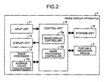
- FIG. 2 is a block diagram of a configuration of the image display apparatus 4.
- the image display apparatus 4 includes an input unit 11 which allows inputting various types of information; a display unit 12 which displays the various types of information; an image processor 13 which processes the input image; a storage unit 14 which stores the various types of information; and a control unit 15 which controls the process and operation of each unit of the image display apparatus 4.
- the input unit 11, the display unit 12, the image processor 13, and the storage unit 14 each are electrically connected to the control unit 15.
- the image display apparatus 4 further includes an interface for the portable recording medium 5 so that the portable recording medium can be detachably equipped.
- the portable recording medium 5 is electrically connected to the control unit 15 when attached to the image display apparatus 4.
- the input unit 11 includes various switches, an input key, a mouse, a touch screen, and the like, and inputs various types of information such as selection information of an image to be displayed.
- An observer of the displayed image as an operator of the image display apparatus 4 performs various operations of reading the displayed image, image selection, image recording and the like via the input unit 11.
- the input unit 11 may include an interface for wired or wireless communication such as a universal serial bus (USB), IEEE1394, or the like so that images can be input by an external device.
- USB universal serial bus
- the display unit 12 includes a liquid crystal display and the like, and displays various types of information such as image data. Particularly, the display unit 12 displays various data such as image data stored in the portable recording medium 5 or the storage unit 14, and the Graphical User Interface (GUI) window which requests the observer or the like of the image display apparatus 4 to input various types of processing information.
- GUI Graphical User Interface
- the storage unit 14 is realized by a ROM in which various processing programs and the like are stored in advance, and a RAM which stores processing parameters for each process, processing data, and the like.
- the storage unit 14 can store image data input via the portable recording medium 5 and the like, image data processed by the image processor 13, display control data processed by an image display controller 15a, and the like.
- the image processor 13 obtains image data from the portable recording medium 5 or the storage unit 14 based on a control by an image processing controller 15b, and performs various image processes on the obtained image data, such as a concentration conversion (gamma conversion and the like), a smoothing (noise elimination and the like), a sharpening (edge emphasis and the like), an image recognition (detection of feature image area, computing of an average color, and the like), and the like.
- concentration conversion gamma conversion and the like
- a smoothing noise elimination and the like
- sharpening edge emphasis and the like
- an image recognition detection of feature image area, computing of an average color, and the like
- the image processor 13 includes an average color calculator 13a that calculates average colors of the series of input images. Specifically, the average color calculator 13a divides each of the series of images into a predetermined plural number of image areas, and calculates an area average-color as an average color by averaging color information of each pixel in respective divided image areas separated as a result of division. The average calculator 13a further calculates a period-area average-color by averaging area average-colors of respective divided image areas of a plurality of images among the series of images with respect to each of equivalent divided image areas in the images, per predetermined period of time, i.e., partial imaging period.
- the control unit 15 is realized by a central processing unit (CPU) and the like which execute various processing programs stored in the storage unit 14. Specifically, the control unit 15 includes the image display controller 15a and the image processing controller 15b.
- the image display controller 15a controls to display a series of images captured at multiple time points as image data stored in the portable recording medium 5 or the storage unit 14 on the display unit 12. As the series of images specifically in the first embodiment, a series of images which capture the inside of organs of the subject 1 at multiple time points are displayed.
- the image display controller 15a controls to display a time scale indicating an imaging period of the series of the intra-subject images, to divide a display area of each time point on the time scale so as to be associated with the divided image areas, and to display area average-colors or period-area average-colors of divided image areas, which are respectively associated with divided scale areas, in the divided scale areas separated as a result of the division.
- the image display controller 15a divides the display area of each time point on the time scale in the same direction as the image division on the display screen of the time scale, and associates the divided scale areas with the divided image areas, respectively.
- the image display controller 15a then controls to display area average-colors or period-area average-colors of the divided image areas, which are respectively associated with the divided scale areas, in the divided scale areas.
- the image display controller 15a accordingly divides the display area of each time point on the time scale into four in the vertical direction (lateral direction) on the display screen in the same manner and associates the divided scale areas with divided image areas respectively in the divided order. Specifically, equivalent left side areas and right sides areas (top level areas and bottom level areas) of the divided scale areas and the divided image areas are associated with each other, respectively. It is preferable that when the time scale is divided in the vertical direction (lateral direction), the time axis of the time scale is set to the vertical direction (lateral direction). It is also preferable that the number of division of the divided image areas and divided scale areas is four or so, however the number thereof is not necessarily limited to four.
- the image processing controller 15b obtains image data stored in the portable recording medium 5 or the storage unit 14 to output to the image processor 13, and controls various image processes of the output image.
- the image processing controller 15b outputs the image data which is the result of processing in the image processor 13 to the storage unit 14 or the portable recording medium 5 for storage.
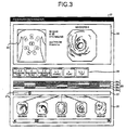
- FIG. 3 illustrates one example of the GUI window displayed based on a control by the image display controller 15a in the image display apparatus 4.
- the display unit 12 displays a window 21 ("Examination/Diagnosis" window) as the GUI window.
- the window 21 includes a main display area 22 which displays a main display image and the like; an image operation area 25 which has various image operation buttons shown as an icon; a color bar 26 and a time bar 27 as a time scale indicating an imaging period of the series of intra-subject images; and a display subarea 28 which exhibits a thumbnail and the like, each being arranged from top to bottom in parallel according to the order described above.
- the main display area 22 exhibits a main display image 23 which is an image selected from the series of intra-subject images based on instruction information input by the input unit 3; and an antenna arrangement plan 24 which schematically illustrates an arrangement of the antennas 6a to 6h on the outside surface of the subject 1.
- the main display area 22 further includes textual information of name, ID number, sex, age, birth date, imaging date, imaging time, and the like of the subject 1, which is associated with the intra-subject image selected as the main display image 23.
- the main display area 22 can house predetermined two or more number of main display images according to a predetermined operation.
- the antenna arrangement plan 24 schematically illustrates an arrangement of the antennas 6a to 6h together with a partial contour of the subject 1.
- an antenna number as an identification of each antenna is shown near each of the antennas 6a to 6h.
- numerals "1" to “8" are denoted for the antenna number, for example.
- the antenna which has maximum reception intensity among the antennas 6a to 6h when the intra-subject image displayed as the main display image 23 is captured, is exhibited discriminably from the other antennas.
- FIG. 3 illustrates a state where, as an antenna having maximum reception intensity, the antenna denoted by "4" is shown discriminably from the other antennas, for example.
- the image display controller 15a can control to display at least one of luminance, hue, and color saturation, of the antenna having the maximum reception intensity so as to be discriminable from the other antennas.
- each imaging time point on the color bar 26 indicates an average color of each intra-subject image captured at each imaging time point. Since the series of intra-subject images have organ-specific average colors respectively, the observer or the like can recognize the organ captured in the intra-subject image of each imaging time point based on the transition of the average colors along the time axis (lateral axis in FIG. 3 ) on the color bar 26.
- the color bar 26 has a format where the entire display area thereof is divided into four in the lateral direction on the display screen.
- Divided color bars 26a to 26d of respective divided levels indicate time-series area average-colors or time-series period-area average-colors on respective levels, which respectively correspond to divided image areas of the series of intra-subject images.
- the average colors of respective intra-subject images are calculated with respect to each divided image area of the entire image area divided into four, and area average-colors or period-area average-colors of respective divided image areas which are respectively associated with the divided scale areas in the divided order, are displayed in the divided scale areas where the display area of each time point is divided into four in the lateral direction on the color bar 26.
- the observer or the like not only can estimate organs captured in intra-subject images at multiple time points, respectively based on the transition in the average colors along the time axis of the divided color bars 26a to 26d of respective levels, but also can easily recognize the detailed condition inside the captured organ depending on the divided image areas. Accordingly, when an average color of a red color group is visually recognized on a divided color bar 26a which is the top level of four levels for a certain period, for example, the observer or the like can recognize that a bleeding site is present inside the organ whose image is captured in the period, the bleeding site is present within the imaged range corresponding to the divided image areas on the top level of all intra-subject images in the period, and the like.
- the observer or the like can recognize the condition of the inside of organs within the imaged range excluding the luminal portion.
- a slider 27a which is movable in the time axis direction is displayed on the time bar 27.
- the slider 27a indicates an imaging time point of an intra-subject image displayed as a main display image 23 on the time bar 27, and moves on the time bar 27 in response to a changeover of the main display image 23.
- any one of image operation buttons in the image operation area 25 is operated via a mouse and the like (not shown)
- an image displayed as the main display image 23 is changed from one to another, and then the slider 27a moves to a position indicating the imaging time point of the intra-subject image displayed as the main display image 23 after the changeover.
- an intra-subject image corresponding to an imaging time point which is indicated by the moved slider 27a is displayed as the main display image 23.
- images are each changed and displayed as the main display image 23 in a row correspondingly to the operations.
- the observer or the like can operate to move the slider 27a to an imaging time point corresponding to an intra-subject image of a desired organ which is picked out with reference to the color bar 26, so that the intra-subject image can be displayed immediately as the main display image 23.
- the left ends of the color bar 26 and the time bar 27 as serving as a time scale indicate an imaging time point of the first image of the time-series intra-subject images.
- the right ends thereof indicate an imaging time point of the last image of the time-series intra-subject images.
- the imaging time point at the left end corresponds to a start time point of image data reception by the receiving device 3
- the imaging time point at the right end corresponds to an end time point of the image data reception.
- an image selected and extracted from the series of intra-subject images is displayed as a thumbnail.
- the intra-subject image displayed as the main display image 23 according to a predetermined button operation or mouse operation is additionally displayed in the display subarea 28 as the thumbnail, for example.
- each thumbnail has individual additional information such as imaging time displayed in the neighborhood as textual information.
- the additional information to be displayed as the textual information is variable according to a predetermined operation. It is also possible to hide the textual information.
- the display subarea 28 includes lines which associate thumbnails and imaging time points of the thumbnails shown on the time bar 27, respectively.
- FIG. 3 illustrates a case where a batch display with up to five thumbnails is allowed.
- thumbnails over the predetermined number replace currently displayed thumbnails and are displayed in response to the operation of the scroll bar displayed in the display subarea 28.
- Each thumbnail displayed in the display subarea 28 is displayed as the main display image 23 in response to the predetermined button operation or mouse operation.
- FIG. 4 is a conceptual diagram of a general procedure for drawing period-area average-color in a divided scale area 26am at a time point Tm on the color bar 26.
- the image processing controller 15b first obtains a predetermined number of intra-subject images P1 to Pn in a predetermined partial imaging period corresponding to the time point Tm.
- the intra-subject images P1 to Pn time-series consecutive images or a series of images extracted in a predetermined sampling period are selectively obtained. Which to be selected either the time-series consecutive images or the series of images extracted in a predetermined sampling period is arbitrarily variable depending on a predetermined operation.
- the image to be selected here may also be an image at one time point.
- the image processing controller 15b controls the image processor 13 to divide each of the intra-subject images Pl to Pn into a plurality of divided image areas.
- FIG. 4 illustrates a state where the intra-subject image P1 is laterally divided into four divided image areas E11 to E14, the intra-subject image Pn is divided into four divided image areas En1 to En4, and other intra-subject images of multiple time points during the period are divided into four divided image areas, respectively in the same manner.
- the image processing controller 15b controls the average color calculator 13a to calculate area average-colors of divided image areas of each of the intra-subject images P1 to Pn, respectively.
- the average color calculator 13a uses color information of all pixels of each divided image area or a plurality of pixels extracted at a predetermined sampling interval to calculate the area average-colors. Which to use for the calculation either all pixels of each divided image area or the plurality of pixels extracted at a predetermined sampling interval is arbitrarily variable depending on a predetermined operation.
- the image processing controller 15b performs averaging of area average-colors of divided image areas equivalent in each of the intra-subject images P1 to Pn, respectively, and calculates period-area average-colors.
- the image processing controller 15b calculates period-area average-colors by averaging area average-colors of the divided image areas on each level of four levels. Specifically, as for divided image areas E11, E21, E31, ... E(n-1)1, En1 on the top level shaded with slash lines in FIG. 4 , for example, the image processing controller 15b averages the area average-colors of these equivalent divided image areas and calculates a period-area average-color Eave1.
- area average-colors of groups of divided image areas E12 to En2; divided image areas E13 to En3; and divided image areas E14 to En4 on the other levels are averaged to calculate period-area average-colors Eave2, Eave3, and Eave4, respectively.
- the image processing controller 15b then associates the period-area average-colors Eave1 to Eave4 with divided image areas on the levels in the intra-subject images P1 to Pn, and the time point Tm, respectively, and then records in the storage unit 14 as average color group Pavem corresponding to the display area at the time point Tm on the color bar 26.
- the image processing controller 15b repeats such series of processes for every time point of the entire imaging period.
- the image display controller 15a obtains a group of average colors of the multiple time points from the storage unit 14 to paint the divided scale areas of the multiple points in the period-area average-colors of divided image areas which are respectively associated with the divided scale areas. Specifically, in FIG. 4 , the divided scale area 26am at the time point Tm of the divided color bar 26a on the top level is painted in the period-area average-color Eave1 which is calculated for the time point Tm by using divided image areas on the top level.
- the image display controller 15a paints the divided scale areas of the multiple time points on the color bar 26 in the period-area average-colors of divided image areas associated by the image processing controller 15b, respectively.
- the image selected as the predetermined number of intra-subject images P1 to Pn is one image at one time point
- the period-area average-colors used in the drawing process is equal to the area average-colors of the image at the one time point.
- FIG. 5 is a flowchart of the procedure of the drawing process of the color bar 26.
- the image processing controller 15b reads a predetermined number of intra-subject images within a predetermined partial imaging period corresponding to the top time point of the time-series period among the series of intra-subject images stored in the portable recording medium 5 or the storage unit 14, and outputs to the image processing controller 13 (step S101).
- the image processing controller 15b controls the image processing controller 13 to divide each of the infra-subject images read at step S101 into a predetermined plural number of divided image areas (step S102).
- each intra-subject image is, for example, divided into four divided image areas.
- the image processing controller 15b controls the average color calculator 13a to calculate area average-colors of respective divided image areas divided at step S102, and performs an average calculation process in which area average-colors of all intra-subject images read at step S101 are averaged to calculate period-area average-colors (step S103).
- the image processing controller 15b then associates the area average-color and the period-area average-color calculated at step S103 respectively with the time point as a processing target and the divided images on respective levels of the intra-subject image, and records the result in the storage unit14 (step S104).
- the image processing controller 15b determines whether the average color calculation process over the entire imaging period is performed or not (step S105).
- the image processing controller 15b repeats the process from step S101 with respect to the time point whose average color is not calculated.
- the image processing controller 15b paints the color bar 26 per divided scale areas of a display area at each time point in the period-area average-colors associated therewith respectively (step S106), and ends the series of color bar drawing process.
- FIG. 6 is a flowchart of a procedure of the average color calculation process.
- the average color calculator 13a first performs a de-gamma process on each intra-subject image as a processing target (step S111).
- the average color calculator 13a calculates area average-colors of respective divided image areas of each intra-subject image (step S112), and calculates period-area average-colors by averaging area average-colors of all intra-subject images as a processing target (step S113).
- the average color calculator 13a performs a gamma process on the processing target of intra-subject images (step S114), and the process returns to step S103.
- step S113 is skipped.
- the average color painted by the image display controller 15a at step S106 is the area average-color instead of a period-area average-color.
- the image display controller 15a controls to display the color bar 26 as a time scale, to divide a display area of each time point on the color bar 26 so as to be associated with the divided image areas, and to display area average-colors or period-area average-colors of divided image areas, which are respectively associated with the divided scale areas separated as a result of the division, in the divided scale areas. Accordingly, a feature of the series of intra-subject images captured at multiple time points can be displayed with respect to each of the display scale areas associated with the divided image areas respectively on the color bar 26 over the entire imaging period. Thus, it is possible for the observer or the like to easily recognize a condition and the like of the imaging target with respect to respective divided image areas at each imaging point.
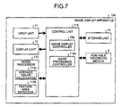
- FIG. 7 is a block diagram of a configuration of an image display apparatus 104 according to the second embodiment.
- the image display apparatus 104 which is prepared based on the image display apparatus 4, has an image processor 113 and a control unit 115 in place of the image processor 13 and the control unit 15 of the image display apparatus 4, respectively.
- the image processor 113 includes an average color calculator 113a and a feature-area detector 113b.
- the control unit 115 includes an image processing calculator 115b in place of the image processing calculator 15b of the control unit 15.
- the other structures of the second embodiment are the same as the first embodiment, and such components are denoted by the same numerals.
- the feature-area detector 113b detects a feature area as a feature image area having a predetermined feature among respective divided image areas of each of the input intra-subject images. In other words, the feature-area detector 113b identifies a predetermined feature such as a bleeding site and the like based on color information of each pixel constituting the intra-subject image for example to detect the feature area.
- the feature-area detector 113b may detect not only a bleeding site but also various sites suspected of being affected such as a discolored site, and an aberrantly-shaped site of the inside the organs as the feature area, for example.
- the feature-area detector 113b may detect the feature area based not only on the color information but also on various types of feature data such as a contour shape, a texture, and a concentration gradient.
- the average color calculator 113a similarly to the average color calculator 13a, calculates average colors of the series of input images. However, the average color calculator 113a weights the color information in a feature area detected by the feature-area detector 113b differently from color information in the divided image area excluding the feature area to calculate an weighted-area average-color averaged as an area average-color. The average color calculator 113a further calculates a period-area average-color by using the weighted-area average-color.
- the average color calculator 113a can weight the area average-color and the weighted-area average-color of the feature image containing the feature area differently from the area average-colors of multiple images excluding the feature image in the partial imaging period to calculate an average weighted-period-area color averaged as a period-area average-color.
- FIG. 8 is a flowchart of the procedure of drawing process of the color bar 26.
- the image processing controller 115b reads a predetermined number of intra-subject images within a predetermined partial imaging period corresponding to the top time point of the time-series period among the series of intra-subject images stored in the portable recording medium 5 or the storage unit 14, and outputs to the image processing controller 113 (step S201).
- the image processing controller 115b controls the image processing controller 113 to divide each of the intra-subject images read at step S201 into a predetermined plural number of divided image areas (step S202).
- each intra-subject image is divided into four divided image areas, for example.
- the image processing controller 115b controls the feature-area detector 113b to detect a feature area having a predetermined feature such as a bleeding site and the like from each of respective divided image areas divided at step S202 (step S203).
- the image processing controller 115b controls the average color calculator 113a to perform an average color calculation process for calculating average colors (step S204).
- the image processing controller 115b then associates the average colors calculated at step S204 with the imaging time point of the processing target image and divided images on each level of the intra-subject image respectively, and stores in the storage unit 14 (step S205). The image processing controller 115b then determines whether the average color calculation process is performed over the entire imaging period or not (step S206).
- the image processing controller 115b repeats the process from step S201 for the time point whose average color is not calculated yet.
- the image processing controller 115b paints the color bar 26 per divided scale areas of a display area at each time point in average colors associated with the divided scale areas, respectively (step S207), and ends the series of color bar drawing process.
- FIG. 9 is a flowchart of a procedure of the average color calculation process.
- the average color calculation process shown in FIG. 9 exemplifies a procedure of a case where a bleeding site is detected as the feature area at step S203.
- the average color calculator 113a performs a de-gamma process on each intra-subject image as a processing target (step S211), and determines whether there are any bleeding sites in respective divided image areas of each intra-subject image or not based on the detection result of the feature area at S203 (step S212).
- the average color calculator 113a similarly to the step S112 shown in FIG. 6 , calculates area average-colors of respective divided image areas of each intra-subject image (step S213).
- the average color calculator 113a greatly weights color information in the feature area indicating each bleeding site compared with color information of the divided image area excluding the feature area, and calculates weighted-area average-color by averaging color information with respect to respective divided image areas (step S214).
- the color information of the divided image area excluding the feature area may be zero-weighted, and the average weighted-area color may be calculated only by using color information in the feature area.
- the average color calculator 113a determines whether there are any bleeding images containing a bleeding site among the predetermined number of processing target intra-subject images (step S215). When no bleeding image is present ("No" at step S215), the average color calculator 113a, similarly to step S113 shown in FIG. 6 , calculates period-area average-colors by averaging area average-colors of all of the processing target intra-subject images (step S216).
- the average color calculator 113a greatly weights area average-colors and weighted-area average-colors of respective bleeding images compared with the area average-colors of intra-subject images other than the bleeding images, and calculates weighted-period-area average-colors (step S217).
- intra-subject images other than bleeding images may be zero- weighted, and the weighted-area average-color may be calculated only by using area average-color and weighted-area average-color of the bleeding image.
- step S216 or step S217 the average color calculator 113a performs a gamma process on each of the processing target intra-subject images (step S218), and the process returns to step S204.
- steps S215 to S217 are skipped.
- the average color painted by the image display controller 115a at step S207 is equal to the area average-color or the weighted-area average-color.
- the feature-area detector 113b detects a feature area having a predetermined feature such as a bleeding site and the like among respective divided image areas of each intra-subject image, and the average color calculator 113a weights at least one of the feature area and the feature image containing the feature area to calculate the weighted-area average-color as an area average-color and the period-area average-color as a period-area average-color.
- the image display controller 15a controls to display an average color which strongly reflects the presence of the feature area in respective divided scale areas on the color bar 26, and to display with an emphasis on the presence of the feature area for respective divided image areas of each imaging time point, and thereby enabling the observer or the like to more easily recognize a condition and the like peculiar to the imaging target.
- the observer or the like can further reduce the possibility of overlooking an image containing a feather area such as a bleeding site, i.e., an area of importance.
- the series of images displayed in the image display apparatus 4 or 104 according to the present invention are explained as the series of intra-subject images which are captured by using the capsule endoscope 2 inserted into the subject 1.
- it is not necessarily limited to the intra-subject images, and may be any images of any subject as long as a series of images are captured at multiple time points by using any imaging device.
- the image display apparatus is useful as an image display apparatus which displays a series of images captured at multiple time points, more specifically as an image display apparatus which displays a series of intra-subject images captured by using a capsule endoscope inserted in a subject.
Landscapes
- Health & Medical Sciences (AREA)
- Life Sciences & Earth Sciences (AREA)
- Engineering & Computer Science (AREA)
- Surgery (AREA)
- Physics & Mathematics (AREA)
- Heart & Thoracic Surgery (AREA)
- General Health & Medical Sciences (AREA)
- Optics & Photonics (AREA)
- Pathology (AREA)
- Radiology & Medical Imaging (AREA)
- Biophysics (AREA)
- Biomedical Technology (AREA)
- Veterinary Medicine (AREA)
- Medical Informatics (AREA)
- Molecular Biology (AREA)
- Animal Behavior & Ethology (AREA)
- Nuclear Medicine, Radiotherapy & Molecular Imaging (AREA)
- Public Health (AREA)
- General Physics & Mathematics (AREA)
- Theoretical Computer Science (AREA)
- Multimedia (AREA)
- Signal Processing (AREA)
- Computer Vision & Pattern Recognition (AREA)
- Endoscopes (AREA)
- Image Processing (AREA)
- Image Analysis (AREA)
- Measurement Of The Respiration, Hearing Ability, Form, And Blood Characteristics Of Living Organisms (AREA)
Abstract
Description
- The present invention relates to an image display apparatus for displaying a series of images captured at multiple time points, specifically to an image display apparatus which is suitable for displaying a series of intra-subject images captured by using a capsule endoscope inserted in the subject.
- In recent years, a swallowable capsule endoscope has been developed in the field of an endoscope. The capsule endoscope having an imaging function and a radio communication function is inserted from a mouth into a body of a subject for an observation, and travels to capture images of the inside of organs such as the stomach, the small intestine, and the large intestine according to their peristalsis until it is naturally excreted.
- While the capsule endoscope travels inside the organs, image data captured by the capsule endoscope in the subject body is sequentially transmitted to the outside of the subject by a radio signal to be stored in a memory provided in a receiver placed outside of the subject, or displayed on a display provided to the receiver. A doctor, a nurse, or the like can make a diagnosis based on images displayed on a display based on the image data stored in the memory, or images displayed on the display provided to the receiver simultaneously with the receiver's data reception.
- Since the number of a series of images captured by the capsule endoscope is usually enormous, the doctor, nurse, or the like needs a great amount of time and effort to observe the enormous number of images and make a diagnosis. In response to such a circumstance, an image display apparatus, which has an improved image search performance and enables an easy recognition of what organ the image on the display captures, has been proposed (see
Patent Document 1, for example). - The image display apparatus displays a time scale which indicates an imaging period of the series of images, and also displays time-series average colors of respective images on the time sale. Since the average colors of the images correspond to captured-organ-specific colors, respectively, the doctor, nurse, or the like can easily recognize, by observing the average color displayed on the time scale, what organ the images at respective imaging time points capture.
- Patent Document 1: Japanese Patent Application Laid-Open No.
2004-337596 - However, since the image display apparatus described above is configured to calculate average color of a whole image area with respect to each image, there has been a problem that, when an area of importance is present at a part of an image area, for example, a bleeding site and the like is present at a part of the image area, it is difficult to recognize the presence of the area of importance based on the average color of the image area. Consequently, there has been a problem of having a possibility that the image capturing the area of importance may be overlooked when images are searched and determined based on an observation of the average color.
- In view of the foregoing, an object of the present invention is to provide an image display apparatus which is capable of displaying a feature of a series of images captured at multiple time points with respect to each display area having a plurality of image areas over an entire imaging period, and enables an easy recognition of a condition and the like of an imaging object with respect to respective image areas of each image captured at each imaging time point.
- To solve the problems described above and to achieve the object an image display apparatus according to
claim 1 for displaying a series of images captured at multiple time points and a time scale indicating an imaging period of the series of images, includes an average color calculator that calculates area average-colors of respective divided image areas prepared by dividing each image among the series of images into predetermined image areas; and a display controller that controls to display the area average-colors of divided image areas that are associated with respective divided scale areas, on the divided scale areas which are prepared by dividing a display area of each time point on the time scale in association with the respective divided image areas. - In the image display apparatus according to the invention as set forth in
claim 2, the area average-colors are period-area average-colors obtained by averaging the area average-colors of a plurality of images for each divided image areas over a predetermined partial imaging period. - In the image display apparatus according to the present invention as set forth in
claim 3, the respective divided image areas are formed by dividing each image into a predetermined dividing direction, and the display controller controls to divide a display area at each time point on the time scale in the same direction as the dividing direction, and to display one of the area average-colors and the period-area average-colors of divided image areas associated with the respective divided scale areas, on the respective divided scale areas associated with the respective divided image areas in the divided order. - In the image display apparatus according to the present invention as set forth in
claim 4, the respective divided image areas are formed by dividing each image into four in a lateral direction and a vertical direction on a display screen, and the display controller controls to divide a display area of each time point on the time scale into four in the lateral direction and the vertical direction on the display screen, and to display one of the area average-colors and the period-area average-colors of divided image areas associated with the respective divided scale areas, on the respective divided scale areas associated with the respective divided image areas in the divided order. - The image display apparatus according to the present invention as set forth in
claim 5, includes a feature-area detector that detects a feature image area having a predetermined feature among the respective divided image areas of the each image, wherein the average color calculator weights differently between color information in the feature image area and color information in each of the divided image areas other than the feature image area respectively, and calculates an averaged weighted-area average-color as the area average-color. - In the image display apparatus according to the present invention as set forth in
claim 6, the weighted-area average-color is a period-area average-color obtained by averaging the weighted-area average-colors of a plurality of images for the every divided image areas in a predetermined partial imaging period. - In the image display apparatus according to the present invention as set forth in claim 7, the average color calculator weights differently between the weighted-area average-colors of the feature images containing the feature image area and the area average-colors of a plurality of images other than the feature images in the partial imaging period, and calculates a weighted-period-area average-color averaged as the period-area average-colors.
- In the image display apparatus according to the present invention as set forth in
claim 8, the average color calculator calculates the period-area average-color by using a series of images in a predetermined sampling period of the partial imaging period. - In the image display apparatus according to the present invention as set forth in claim 9, the average color calculator calculates the area average-color by using color information of each pixel at a predetermined sampling interval in the divided image areas.
- In the image display apparatus according to the present invention as set forth in claim 10, the series of images are intra-subject images captured by using a capsule endoscope inserted in a subject.
- The image display apparatus according to the present invention is capable of displaying a feature of a series of images captured at multiple time points with respect to each display area having a plurality of image areas over an entire imaging period, and enables an easy recognition of a condition and the like of an imaging object with respect to respective image areas of each image captured at each imaging time point.
-
-
FIG. 1 is a schematic diagram of a configuration of a radio system for acquiring intra-subject information according to a first embodiment; -
FIG. 2 is a block diagram of a configuration of an image display apparatus according to the first embodiment; -
FIG. 3 illustrates a display screen image of the image display apparatus shown inFIG. 1 ; -
FIG. 4 is a diagram of a drawing process of the color bar shown inFIG. 3 ; -
FIG. 5 is a flowchart of a procedure of the color bar drawing process performed by the image display apparatus shown inFIG. 1 ; -
FIG. 6 is a flowchart of a procedure of the average color calculation process shown inFIG. 5 ; -
FIG. 7 is a block diagram of a configuration of an image display apparatus according to a second embodiment of the present invention; -
FIG. 8 is a flowchart of a procedure of a color bar drawing process performed by the image display apparatus shown inFIG. 7 ; and -
FIG. 9 is a flowchart of a procedure of the average color calculation process shown inFIG. 8 . -
- 1
- SUBJECT
- 2
- CAPSULE ENDOSCOPE
- 3
- RECEIVING DEVICE
- 4
- IMAGE DISPLAY APPARATUS
- 5
- PORTABLE RECORDING MEDIUM
- 6
- RECEIVING ANTENNA
- 6a to 6h
- ANTENNAS
- 11
- INPUT UNIT
- 12
- DISPLAY UNIT
- 13
- IMAGE PROCESSOR
- 13a
- AVERAGE COLOR CALCULATOR
- 14
- STORAGE UNIT
- 15
- CONTROL UNIT
- 15a
- IMAGE DISPLAY CONTROLLER
- 15b
- IMAGE PROCESSING CONTROLLER
- 21
- WINDOW
- 22
- MAIN DISPLAY AREA
- 23
- MAIN DISPLAY IMAGE
- 24
- ANTENNA ARRANGEMENT PLAN
- 25
- IMAGE OPERATION AREA
- 26
- COLOR BAR
- 26a to 26d
- DIVIDED COLOR BARS
- 27
- TIME BAR
- 27a
- SLIDER
- 28
- DISPLAY SUBAREA
- Exemplary embodiments of a radio system for acquiring intra-subject information as a preferred embodiment of an image display apparatus according to the present invention will be explained in detail with reference to the accompanying drawings. However, the present invention shall not be limited to the embodiments. Throughout the drawings, the same part is denoted by the same numeral.
- (First embodiment) First, a radio system for acquiring intra-subject information provided with an image display apparatus according to a first embodiment will be explained.
FIG. 1 is a schematic diagram of an entire configuration of the radio system for acquiring intra-subject information. The radio system for acquiring intra-subject information uses a capsule endoscope as one example of a body-insertable device. - As shown in
FIG. 1 , the radio system for acquiring intra-subject information includes acapsule endoscope 2 which is inserted into a body of a subject 1 to wirelessly transmit image data of a captured intra-subject image to areceiving device 3; the receivingdevice 3 which receives the image data wirelessly transmitted from thecapsule endoscope 2; animage display apparatus 4 which displays the intra-subject image based on an image signal received by the receivingdevice 3; and aportable recording medium 5 which transfers image data and the like between the receivingdevice 3 and theimage display apparatus 4. - The receiving
device 3 include a receivingantenna 6 having a plurality ofantennas 6a to 6h which are attached on an outside surface of thesubject 1. The receivingdevice 3 receives image data and the like wirelessly transmitted from thecapsule endoscope 2 via the receivingantenna 6, and records every piece of the received image data so as to associate with reception intensity information ofrespective antennas 6a to 6h at the time of data reception. - The
antennas 6a to 6h realized by a loop antenna for example, are disposed at predetermined positions on the outside surface of the subject 1, i.e., positions respectively corresponding to organs as a path of thecapsule endoscope 2 inside thesubject 1. Theantennas 6a to 6h may be arranged at predetermined positions on a jacket or the like to be worn by thesubject 1. In this case, theantennas 6a to 6h are arranged at predetermined positions on the outside surface of the subject 1 through the jacket or the like. An arrangement of theantennas 6a to 6h may be changed arbitrarily depending on the purposes such as an observation, a diagnosis, or the like of thesubject 1. The number of antennas provided to the receivingantenna 6 is not necessarily limited to eight as explained here asantennas 6a to 6h, and may be less or more than eight. - The
image display apparatus 4 realized by a work station having a cathode-ray tube (CRT), a liquid crystal display, or the like for example, displays an image based on image data obtained via theportable recording medium 5 or the like. Theimage display apparatus 4 may output the image data to an output device such as a printer. Theimage display apparatus 4 has a function of communicating with an external device, and obtains/outputs the image data via wired or radio communication. - The
portable recording medium 5 realized by a compact flash (registered trademark) memory, CD, DVD and the like, is detachable with respect to the receivingdevice 3 and theimage display apparatus 4, and can record or output various types of information such as the image data and the like when theportable recording medium 5 is attached to the receivingdevice 3 and theimage display apparatus 4. For example, theportable recording medium 5 is attached to the receivingdevice 3 and records the image data and the like transmitted from thecapsule endoscope 2 to the receivingdevice 3, while thecapsule endoscope 2 travels inside thesubject 1. After thecapsule endoscope 2 is discharged from thesubject 1, theportable recording medium 5 is removed from the receivingdevice 3 and attached to theimage display apparatus 4 to output the recorded image data and the like to theimage display apparatus 4. Since the image data is transferred between the receivingdevice 3 and theimage display device 4 via theportable recording medium 5, the subject 1 can freely move while thecapsule endoscope 2 is in thesubject 1. The image data may be transferred through wired or radio communication between the receivingdevice 3 and theimage display apparatus 4. - Next, a configuration of the
image display apparatus 4 according to the first embodiment will be explained.FIG. 2 is a block diagram of a configuration of theimage display apparatus 4. As shown inFIG. 2 , theimage display apparatus 4 includes aninput unit 11 which allows inputting various types of information; adisplay unit 12 which displays the various types of information; animage processor 13 which processes the input image; astorage unit 14 which stores the various types of information; and acontrol unit 15 which controls the process and operation of each unit of theimage display apparatus 4. Theinput unit 11, thedisplay unit 12, theimage processor 13, and thestorage unit 14 each are electrically connected to thecontrol unit 15. Theimage display apparatus 4 further includes an interface for theportable recording medium 5 so that the portable recording medium can be detachably equipped. Theportable recording medium 5 is electrically connected to thecontrol unit 15 when attached to theimage display apparatus 4. - The
input unit 11 includes various switches, an input key, a mouse, a touch screen, and the like, and inputs various types of information such as selection information of an image to be displayed. An observer of the displayed image as an operator of theimage display apparatus 4 performs various operations of reading the displayed image, image selection, image recording and the like via theinput unit 11. Theinput unit 11 may include an interface for wired or wireless communication such as a universal serial bus (USB), IEEE1394, or the like so that images can be input by an external device. - The
display unit 12 includes a liquid crystal display and the like, and displays various types of information such as image data. Particularly, thedisplay unit 12 displays various data such as image data stored in theportable recording medium 5 or thestorage unit 14, and the Graphical User Interface (GUI) window which requests the observer or the like of theimage display apparatus 4 to input various types of processing information. - The
storage unit 14 is realized by a ROM in which various processing programs and the like are stored in advance, and a RAM which stores processing parameters for each process, processing data, and the like. Thestorage unit 14 can store image data input via theportable recording medium 5 and the like, image data processed by theimage processor 13, display control data processed by animage display controller 15a, and the like. - The
image processor 13 obtains image data from theportable recording medium 5 or thestorage unit 14 based on a control by animage processing controller 15b, and performs various image processes on the obtained image data, such as a concentration conversion (gamma conversion and the like), a smoothing (noise elimination and the like), a sharpening (edge emphasis and the like), an image recognition (detection of feature image area, computing of an average color, and the like), and the like. - The
image processor 13 includes anaverage color calculator 13a that calculates average colors of the series of input images. Specifically, theaverage color calculator 13a divides each of the series of images into a predetermined plural number of image areas, and calculates an area average-color as an average color by averaging color information of each pixel in respective divided image areas separated as a result of division. Theaverage calculator 13a further calculates a period-area average-color by averaging area average-colors of respective divided image areas of a plurality of images among the series of images with respect to each of equivalent divided image areas in the images, per predetermined period of time, i.e., partial imaging period. - The
control unit 15 is realized by a central processing unit (CPU) and the like which execute various processing programs stored in thestorage unit 14. Specifically, thecontrol unit 15 includes theimage display controller 15a and theimage processing controller 15b. Theimage display controller 15a controls to display a series of images captured at multiple time points as image data stored in theportable recording medium 5 or thestorage unit 14 on thedisplay unit 12. As the series of images specifically in the first embodiment, a series of images which capture the inside of organs of the subject 1 at multiple time points are displayed. - Specifically, the
image display controller 15a controls to display a time scale indicating an imaging period of the series of the intra-subject images, to divide a display area of each time point on the time scale so as to be associated with the divided image areas, and to display area average-colors or period-area average-colors of divided image areas, which are respectively associated with divided scale areas, in the divided scale areas separated as a result of the division. - More specifically, when the
average color calculator 13a divides each image into a predetermined direction, theimage display controller 15a divides the display area of each time point on the time scale in the same direction as the image division on the display screen of the time scale, and associates the divided scale areas with the divided image areas, respectively. Theimage display controller 15a then controls to display area average-colors or period-area average-colors of the divided image areas, which are respectively associated with the divided scale areas, in the divided scale areas. - In this case, when the
average color calculator 13a divides each image into four in the vertical direction (lateral direction) on the display screen for example, theimage display controller 15a accordingly divides the display area of each time point on the time scale into four in the vertical direction (lateral direction) on the display screen in the same manner and associates the divided scale areas with divided image areas respectively in the divided order. Specifically, equivalent left side areas and right sides areas (top level areas and bottom level areas) of the divided scale areas and the divided image areas are associated with each other, respectively. It is preferable that when the time scale is divided in the vertical direction (lateral direction), the time axis of the time scale is set to the vertical direction (lateral direction). It is also preferable that the number of division of the divided image areas and divided scale areas is four or so, however the number thereof is not necessarily limited to four. - The
image processing controller 15b obtains image data stored in theportable recording medium 5 or thestorage unit 14 to output to theimage processor 13, and controls various image processes of the output image. Theimage processing controller 15b outputs the image data which is the result of processing in theimage processor 13 to thestorage unit 14 or theportable recording medium 5 for storage. - Next, the display window (GUI window) which is displayed on the
display unit 12 in theimage display apparatus 4 will be explained.FIG. 3 illustrates one example of the GUI window displayed based on a control by theimage display controller 15a in theimage display apparatus 4. As shown inFIG. 3 , thedisplay unit 12 displays a window 21 ("Examination/Diagnosis" window) as the GUI window. Thewindow 21 includes amain display area 22 which displays a main display image and the like; animage operation area 25 which has various image operation buttons shown as an icon; acolor bar 26 and atime bar 27 as a time scale indicating an imaging period of the series of intra-subject images; and adisplay subarea 28 which exhibits a thumbnail and the like, each being arranged from top to bottom in parallel according to the order described above. - The
main display area 22 exhibits a main display image 23 which is an image selected from the series of intra-subject images based on instruction information input by theinput unit 3; and anantenna arrangement plan 24 which schematically illustrates an arrangement of theantennas 6a to 6h on the outside surface of thesubject 1. Themain display area 22 further includes textual information of name, ID number, sex, age, birth date, imaging date, imaging time, and the like of the subject 1, which is associated with the intra-subject image selected as the main display image 23. Themain display area 22 can house predetermined two or more number of main display images according to a predetermined operation. - The
antenna arrangement plan 24 schematically illustrates an arrangement of theantennas 6a to 6h together with a partial contour of thesubject 1. In theantenna arrangement plan 24, an antenna number as an identification of each antenna is shown near each of theantennas 6a to 6h. InFIG. 3 , numerals "1" to "8" are denoted for the antenna number, for example. In theantenna arrangement plan 24, the antenna which has maximum reception intensity among theantennas 6a to 6h when the intra-subject image displayed as the main display image 23 is captured, is exhibited discriminably from the other antennas.FIG. 3 illustrates a state where, as an antenna having maximum reception intensity, the antenna denoted by "4" is shown discriminably from the other antennas, for example. To realize a discriminative display, theimage display controller 15a can control to display at least one of luminance, hue, and color saturation, of the antenna having the maximum reception intensity so as to be discriminable from the other antennas. - In the
color bar 26, average colors of images in the series of intra-subject images are exhibited respectively in the time-series order as a whole. Specifically, a display area of each imaging time point on thecolor bar 26 indicates an average color of each intra-subject image captured at each imaging time point. Since the series of intra-subject images have organ-specific average colors respectively, the observer or the like can recognize the organ captured in the intra-subject image of each imaging time point based on the transition of the average colors along the time axis (lateral axis inFIG. 3 ) on thecolor bar 26. - The
color bar 26 has a format where the entire display area thereof is divided into four in the lateral direction on the display screen. Dividedcolor bars 26a to 26d of respective divided levels indicate time-series area average-colors or time-series period-area average-colors on respective levels, which respectively correspond to divided image areas of the series of intra-subject images. In other words, the average colors of respective intra-subject images are calculated with respect to each divided image area of the entire image area divided into four, and area average-colors or period-area average-colors of respective divided image areas which are respectively associated with the divided scale areas in the divided order, are displayed in the divided scale areas where the display area of each time point is divided into four in the lateral direction on thecolor bar 26. - According to the
color bar 26, the observer or the like not only can estimate organs captured in intra-subject images at multiple time points, respectively based on the transition in the average colors along the time axis of the dividedcolor bars 26a to 26d of respective levels, but also can easily recognize the detailed condition inside the captured organ depending on the divided image areas. Accordingly, when an average color of a red color group is visually recognized on a dividedcolor bar 26a which is the top level of four levels for a certain period, for example, the observer or the like can recognize that a bleeding site is present inside the organ whose image is captured in the period, the bleeding site is present within the imaged range corresponding to the divided image areas on the top level of all intra-subject images in the period, and the like. Moreover, when an average color of a black color group in an image area including the.luminal portion is displayed on a level of the divided color bars different from the level on which an average color of the other image areas is displayed, the observer or the like can recognize the condition of the inside of organs within the imaged range excluding the luminal portion. - A
slider 27a which is movable in the time axis direction is displayed on thetime bar 27. Theslider 27a indicates an imaging time point of an intra-subject image displayed as a main display image 23 on thetime bar 27, and moves on thetime bar 27 in response to a changeover of the main display image 23. For example, when any one of image operation buttons in theimage operation area 25 is operated via a mouse and the like (not shown), an image displayed as the main display image 23 is changed from one to another, and then theslider 27a moves to a position indicating the imaging time point of the intra-subject image displayed as the main display image 23 after the changeover. - In contrast, when the
slider 27a is operated to move by the mouse and the like, an intra-subject image corresponding to an imaging time point which is indicated by the movedslider 27a is displayed as the main display image 23. When theslider 27a is operated to move in a row, images are each changed and displayed as the main display image 23 in a row correspondingly to the operations. According to theslider 27a, the observer or the like can operate to move theslider 27a to an imaging time point corresponding to an intra-subject image of a desired organ which is picked out with reference to thecolor bar 26, so that the intra-subject image can be displayed immediately as the main display image 23. - The left ends of the
color bar 26 and thetime bar 27 as serving as a time scale, indicate an imaging time point of the first image of the time-series intra-subject images. The right ends thereof indicate an imaging time point of the last image of the time-series intra-subject images. Normally, the imaging time point at the left end corresponds to a start time point of image data reception by the receivingdevice 3, and the imaging time point at the right end corresponds to an end time point of the image data reception. - In the
display subarea 28, an image selected and extracted from the series of intra-subject images is displayed as a thumbnail. Specifically, the intra-subject image displayed as the main display image 23 according to a predetermined button operation or mouse operation is additionally displayed in thedisplay subarea 28 as the thumbnail, for example. - In the
display subarea 28, each thumbnail has individual additional information such as imaging time displayed in the neighborhood as textual information. The additional information to be displayed as the textual information is variable according to a predetermined operation. It is also possible to hide the textual information. Thedisplay subarea 28 includes lines which associate thumbnails and imaging time points of the thumbnails shown on thetime bar 27, respectively. - Since there is a limitation in the display area available for the
display subarea 28, a batch display with up to a predetermined number of thumbnails can be allowed.FIG. 3 , for example, illustrates a case where a batch display with up to five thumbnails is allowed. When the number of extracted thumbnails is greater than the predetermined number for the batch display, thumbnails over the predetermined number replace currently displayed thumbnails and are displayed in response to the operation of the scroll bar displayed in thedisplay subarea 28. Each thumbnail displayed in thedisplay subarea 28 is displayed as the main display image 23 in response to the predetermined button operation or mouse operation. - Here, a drawing process of the
color bar 26 in theimage display apparatus 4 according to the first embodiment will be explained.FIG. 4 is a conceptual diagram of a general procedure for drawing period-area average-color in a divided scale area 26am at a time point Tm on thecolor bar 26. - For the drawing of period-area average-colors on the
color bar 26 as shown inFIG. 4 , theimage processing controller 15b first obtains a predetermined number of intra-subject images P1 to Pn in a predetermined partial imaging period corresponding to the time point Tm. Here, as the intra-subject images P1 to Pn, time-series consecutive images or a series of images extracted in a predetermined sampling period are selectively obtained. Which to be selected either the time-series consecutive images or the series of images extracted in a predetermined sampling period is arbitrarily variable depending on a predetermined operation. The image to be selected here may also be an image at one time point. - Subsequently, the
image processing controller 15b controls theimage processor 13 to divide each of the intra-subject images Pl to Pn into a plurality of divided image areas. For example,FIG. 4 illustrates a state where the intra-subject image P1 is laterally divided into four divided image areas E11 to E14, the intra-subject image Pn is divided into four divided image areas En1 to En4, and other intra-subject images of multiple time points during the period are divided into four divided image areas, respectively in the same manner. - Next, the
image processing controller 15b controls theaverage color calculator 13a to calculate area average-colors of divided image areas of each of the intra-subject images P1 to Pn, respectively. At this point, theaverage color calculator 13a uses color information of all pixels of each divided image area or a plurality of pixels extracted at a predetermined sampling interval to calculate the area average-colors. Which to use for the calculation either all pixels of each divided image area or the plurality of pixels extracted at a predetermined sampling interval is arbitrarily variable depending on a predetermined operation. - Then, the
image processing controller 15b performs averaging of area average-colors of divided image areas equivalent in each of the intra-subject images P1 to Pn, respectively, and calculates period-area average-colors. In other words, theimage processing controller 15b calculates period-area average-colors by averaging area average-colors of the divided image areas on each level of four levels. Specifically, as for divided image areas E11, E21, E31, ... E(n-1)1, En1 on the top level shaded with slash lines inFIG. 4 , for example, theimage processing controller 15b averages the area average-colors of these equivalent divided image areas and calculates a period-area average-color Eave1. In the same manner, area average-colors of groups of divided image areas E12 to En2; divided image areas E13 to En3; and divided image areas E14 to En4 on the other levels, are averaged to calculate period-area average-colors Eave2, Eave3, and Eave4, respectively. - The
image processing controller 15b then associates the period-area average-colors Eave1 to Eave4 with divided image areas on the levels in the intra-subject images P1 to Pn, and the time point Tm, respectively, and then records in thestorage unit 14 as average color group Pavem corresponding to the display area at the time point Tm on thecolor bar 26. Theimage processing controller 15b repeats such series of processes for every time point of the entire imaging period. - After the
image processing controller 15b calculates all average colors of multiple time points to be drawn on thecolor bar 26, theimage display controller 15a obtains a group of average colors of the multiple time points from thestorage unit 14 to paint the divided scale areas of the multiple points in the period-area average-colors of divided image areas which are respectively associated with the divided scale areas. Specifically, inFIG. 4 , the divided scale area 26am at the time point Tm of the dividedcolor bar 26a on the top level is painted in the period-area average-color Eave1 which is calculated for the time point Tm by using divided image areas on the top level. - In the same manner, the
image display controller 15a paints the divided scale areas of the multiple time points on thecolor bar 26 in the period-area average-colors of divided image areas associated by theimage processing controller 15b, respectively. When the image selected as the predetermined number of intra-subject images P1 to Pn is one image at one time point, the period-area average-colors used in the drawing process is equal to the area average-colors of the image at the one time point. - Here, a procedure of the drawing process of the
color bar 26 performed in theimage display apparatus 4 according to the first embodiment will be explained.FIG. 5 is a flowchart of the procedure of the drawing process of thecolor bar 26. As shown inFIG. 5 , theimage processing controller 15b reads a predetermined number of intra-subject images within a predetermined partial imaging period corresponding to the top time point of the time-series period among the series of intra-subject images stored in theportable recording medium 5 or thestorage unit 14, and outputs to the image processing controller 13 (step S101). - Then, the
image processing controller 15b controls theimage processing controller 13 to divide each of the infra-subject images read at step S101 into a predetermined plural number of divided image areas (step S102). At step S102, each intra-subject image is, for example, divided into four divided image areas. Next, theimage processing controller 15b controls theaverage color calculator 13a to calculate area average-colors of respective divided image areas divided at step S102, and performs an average calculation process in which area average-colors of all intra-subject images read at step S101 are averaged to calculate period-area average-colors (step S103). - The
image processing controller 15b then associates the area average-color and the period-area average-color calculated at step S103 respectively with the time point as a processing target and the divided images on respective levels of the intra-subject image, and records the result in the storage unit14 (step S104). Theimage processing controller 15b determines whether the average color calculation process over the entire imaging period is performed or not (step S105). - When the average colors of the entire imaging period are not calculated ("No" at step S105), the
image processing controller 15b repeats the process from step S101 with respect to the time point whose average color is not calculated. On the other hand, when all average colors of the entire imaging period are calculated ("Yes" at step S105), theimage processing controller 15b paints thecolor bar 26 per divided scale areas of a display area at each time point in the period-area average-colors associated therewith respectively (step S106), and ends the series of color bar drawing process. - Next, the average color calculator at step S103 will be explained.
FIG. 6 is a flowchart of a procedure of the average color calculation process. As shown inFIG. 6 , theaverage color calculator 13a first performs a de-gamma process on each intra-subject image as a processing target (step S111). Next, theaverage color calculator 13a calculates area average-colors of respective divided image areas of each intra-subject image (step S112), and calculates period-area average-colors by averaging area average-colors of all intra-subject images as a processing target (step S113). Subsequently, theaverage color calculator 13a performs a gamma process on the processing target of intra-subject images (step S114), and the process returns to step S103. - When the image read by the
image processing controller 15b at step S101 is one intra-subject image at one time point, step S113 is skipped. In this case, the average color painted by theimage display controller 15a at step S106 is the area average-color instead of a period-area average-color. - As explained above, in the
image display apparatus 4 according to the first embodiment, theimage display controller 15a controls to display thecolor bar 26 as a time scale, to divide a display area of each time point on thecolor bar 26 so as to be associated with the divided image areas, and to display area average-colors or period-area average-colors of divided image areas, which are respectively associated with the divided scale areas separated as a result of the division, in the divided scale areas. Accordingly, a feature of the series of intra-subject images captured at multiple time points can be displayed with respect to each of the display scale areas associated with the divided image areas respectively on thecolor bar 26 over the entire imaging period. Thus, it is possible for the observer or the like to easily recognize a condition and the like of the imaging target with respect to respective divided image areas at each imaging point. - (Second embodiment) Next, a second embodiment according to the present invention will be explained. In the first embodiment described above, the intra-subject images are processed uniformly to calculate average colors. However, in the second embodiment, a feature area such as a bleeding site and the like contained in intra-subject images is weighted to calculate average colors.
-
FIG. 7 is a block diagram of a configuration of animage display apparatus 104 according to the second embodiment. As shown inFIG. 7 , theimage display apparatus 104, which is prepared based on theimage display apparatus 4, has animage processor 113 and acontrol unit 115 in place of theimage processor 13 and thecontrol unit 15 of theimage display apparatus 4, respectively. Theimage processor 113 includes anaverage color calculator 113a and a feature-area detector 113b. Thecontrol unit 115 includes animage processing calculator 115b in place of theimage processing calculator 15b of thecontrol unit 15. The other structures of the second embodiment are the same as the first embodiment, and such components are denoted by the same numerals. - The feature-
area detector 113b detects a feature area as a feature image area having a predetermined feature among respective divided image areas of each of the input intra-subject images. In other words, the feature-area detector 113b identifies a predetermined feature such as a bleeding site and the like based on color information of each pixel constituting the intra-subject image for example to detect the feature area. The feature-area detector 113b may detect not only a bleeding site but also various sites suspected of being affected such as a discolored site, and an aberrantly-shaped site of the inside the organs as the feature area, for example. The feature-area detector 113b may detect the feature area based not only on the color information but also on various types of feature data such as a contour shape, a texture, and a concentration gradient. - The
average color calculator 113a, similarly to theaverage color calculator 13a, calculates average colors of the series of input images. However, theaverage color calculator 113a weights the color information in a feature area detected by the feature-area detector 113b differently from color information in the divided image area excluding the feature area to calculate an weighted-area average-color averaged as an area average-color. Theaverage color calculator 113a further calculates a period-area average-color by using the weighted-area average-color. Furthermore, theaverage color calculator 113a can weight the area average-color and the weighted-area average-color of the feature image containing the feature area differently from the area average-colors of multiple images excluding the feature image in the partial imaging period to calculate an average weighted-period-area color averaged as a period-area average-color. - Here, a procedure of a drawing process of the
color bar 26 performed by theimage display apparatus 104 will be explained.FIG. 8 is a flowchart of the procedure of drawing process of thecolor bar 26. As shown inFIG. 8 , theimage processing controller 115b reads a predetermined number of intra-subject images within a predetermined partial imaging period corresponding to the top time point of the time-series period among the series of intra-subject images stored in theportable recording medium 5 or thestorage unit 14, and outputs to the image processing controller 113 (step S201). - Then, the
image processing controller 115b controls theimage processing controller 113 to divide each of the intra-subject images read at step S201 into a predetermined plural number of divided image areas (step S202). At step S202, each intra-subject image is divided into four divided image areas, for example. Next, theimage processing controller 115b controls the feature-area detector 113b to detect a feature area having a predetermined feature such as a bleeding site and the like from each of respective divided image areas divided at step S202 (step S203). Subsequently, theimage processing controller 115b controls theaverage color calculator 113a to perform an average color calculation process for calculating average colors (step S204). - The
image processing controller 115b then associates the average colors calculated at step S204 with the imaging time point of the processing target image and divided images on each level of the intra-subject image respectively, and stores in the storage unit 14 (step S205). Theimage processing controller 115b then determines whether the average color calculation process is performed over the entire imaging period or not (step S206). - When the average colors of the entire imaging period are not calculated ("No" at step S206), the
image processing controller 115b repeats the process from step S201 for the time point whose average color is not calculated yet. On the other hand, when all average colors of the entire imaging period are calculated ("Yes" at step S206), theimage processing controller 115b paints thecolor bar 26 per divided scale areas of a display area at each time point in average colors associated with the divided scale areas, respectively (step S207), and ends the series of color bar drawing process. - Next, the average color calculator at step S204 will be explained.
FIG. 9 is a flowchart of a procedure of the average color calculation process. The average color calculation process shown inFIG. 9 exemplifies a procedure of a case where a bleeding site is detected as the feature area at step S203. - As shown in
FIG. 9 , theaverage color calculator 113a performs a de-gamma process on each intra-subject image as a processing target (step S211), and determines whether there are any bleeding sites in respective divided image areas of each intra-subject image or not based on the detection result of the feature area at S203 (step S212). When no bleeding site is present ("No" at step S212), theaverage color calculator 113a, similarly to the step S112 shown inFIG. 6 , calculates area average-colors of respective divided image areas of each intra-subject image (step S213). - On the other hand, when a bleeding site is present ("Yes" at step S214), the
average color calculator 113a greatly weights color information in the feature area indicating each bleeding site compared with color information of the divided image area excluding the feature area, and calculates weighted-area average-color by averaging color information with respect to respective divided image areas (step S214). At step S214, the color information of the divided image area excluding the feature area may be zero-weighted, and the average weighted-area color may be calculated only by using color information in the feature area. - After step S213 or step S214, the
average color calculator 113a determines whether there are any bleeding images containing a bleeding site among the predetermined number of processing target intra-subject images (step S215). When no bleeding image is present ("No" at step S215), theaverage color calculator 113a, similarly to step S113 shown inFIG. 6 , calculates period-area average-colors by averaging area average-colors of all of the processing target intra-subject images (step S216). - On the other hand, when a bleeding image is present ("Yes" at step S215), the
average color calculator 113a greatly weights area average-colors and weighted-area average-colors of respective bleeding images compared with the area average-colors of intra-subject images other than the bleeding images, and calculates weighted-period-area average-colors (step S217). At step S217, intra-subject images other than bleeding images may be zero- weighted, and the weighted-area average-color may be calculated only by using area average-color and weighted-area average-color of the bleeding image. - After step S216 or step S217, the
average color calculator 113a performs a gamma process on each of the processing target intra-subject images (step S218), and the process returns to step S204. - When the image read by the
image processing controller 115b at step S201 is one intra-subject image at one time point, steps S215 to S217 are skipped. In this case, the average color painted by the image display controller 115a at step S207 is equal to the area average-color or the weighted-area average-color. - As described above, in the
image display apparatus 104 according to the second embodiment, the feature-area detector 113b detects a feature area having a predetermined feature such as a bleeding site and the like among respective divided image areas of each intra-subject image, and theaverage color calculator 113a weights at least one of the feature area and the feature image containing the feature area to calculate the weighted-area average-color as an area average-color and the period-area average-color as a period-area average-color. Thus, theimage display controller 15a controls to display an average color which strongly reflects the presence of the feature area in respective divided scale areas on thecolor bar 26, and to display with an emphasis on the presence of the feature area for respective divided image areas of each imaging time point, and thereby enabling the observer or the like to more easily recognize a condition and the like peculiar to the imaging target. Thus, the observer or the like can further reduce the possibility of overlooking an image containing a feather area such as a bleeding site, i.e., an area of importance. - In the first and second embodiments described above, the series of images displayed in the
image display apparatus capsule endoscope 2 inserted into thesubject 1. However, it is not necessarily limited to the intra-subject images, and may be any images of any subject as long as a series of images are captured at multiple time points by using any imaging device. - The image display apparatus according to the present invention is useful as an image display apparatus which displays a series of images captured at multiple time points, more specifically as an image display apparatus which displays a series of intra-subject images captured by using a capsule endoscope inserted in a subject.
Claims (10)
- An image display apparatus for displaying a series of images captured at multiple time points and a time scale indicating an imaging period of the series of images, comprising:an average color calculator that calculates area average-colors of respective divided image areas prepared by dividing each image among the series of images into predetermined image areas; anda display controller that controls to display the area average-colors of divided image areas that are associated with respective divided scale areas, on the divided scale areas which are prepared by dividing a display area of each time point on the time scale in association with the respective divided image areas.
- The image display apparatus according to claim 1, wherein the area average-colors are period-area average-colors obtained by averaging the area average-colors of a plurality of images for each divided image areas over a predetermined partial imaging period.
- The image display apparatus according to claim 1 or 2, wherein
the respective divided image areas are formed by dividing each image into a predetermined dividing direction, and
the display controller controls to divide a display area at each time point on the time scale in the same direction as the dividing direction, and to display one of the area average-colors and the period-area average-colors of divided image areas associated with the respective divided scale areas, on the respective divided scale areas associated with the respective divided image areas in the divided order. - The image display apparatus according to claim 3, wherein
the respective divided image areas are formed by dividing each image into four in a lateral direction and a vertical direction on a display screen, and
the display controller controls to divide a display area of each time point on the time scale into four in the lateral direction and the vertical direction on the display screen, and to display one of the area average-colors and the period-area average-colors of divided image areas associated with the respective divided scale areas, on the respective divided scale areas associated with the respective divided image areas in the divided order. - The image display apparatus according to any one of claims 1 to 4, comprising:a feature-area detector that detects a feature image area having a predetermined feature among the respective divided image areas of the each image, whereinthe average color calculator weights differently between color information in the feature image area and color information in each of the divided image areas other than the feature image area respectively, and calculates an averaged weighted-area average-color as the area average-color.
- The image display apparatus according to claim 5, wherein the weighted-area average-color is a period-area average-color obtained by averaging the weighted-area average-colors of a plurality of images for the every divided image areas in a predetermined partial imaging period.
- The image display apparatus according to claim 6, wherein the average color calculator weights differently between the weighted-area average-colors of the feature images containing the feature image area and the area average-colors of a plurality of images other than the feature images in the partial imaging period, and calculates a weighted-period-area average-color averaged as the period-area average-colors.
- The image display apparatus according to any one of claims 1 to 7, wherein the average color calculator calculates the period-area average-color by using a series of images in a predetermined sampling period of the partial imaging period.
- The image display apparatus according to any one of claims 1 to 8, wherein the average color calculator calculates the area average-color by using color information of each pixel at a predetermined sampling interval in the divided image areas.
- The image display apparatus according to any one of claims 1 to 9, wherein the series of images are intra-subject images captured by using a capsule endoscope inserted in a subject.
Applications Claiming Priority (2)
| Application Number | Priority Date | Filing Date | Title |
|---|---|---|---|
| JP2005263089A JP4464894B2 (en) | 2005-09-09 | 2005-09-09 | Image display device |
| PCT/JP2006/317005 WO2007029569A1 (en) | 2005-09-09 | 2006-08-29 | Image display device |
Publications (3)
| Publication Number | Publication Date |
|---|---|
| EP1922979A1 true EP1922979A1 (en) | 2008-05-21 |
| EP1922979A4 EP1922979A4 (en) | 2010-10-06 |
| EP1922979B1 EP1922979B1 (en) | 2012-01-04 |
Family
ID=37835690
Family Applications (1)
| Application Number | Title | Priority Date | Filing Date |
|---|---|---|---|
| EP06796982A Not-in-force EP1922979B1 (en) | 2005-09-09 | 2006-08-29 | Image display apparatus |
Country Status (5)
| Country | Link |
|---|---|
| US (1) | US8406489B2 (en) |
| EP (1) | EP1922979B1 (en) |
| JP (1) | JP4464894B2 (en) |
| CN (1) | CN101257835B (en) |
| WO (1) | WO2007029569A1 (en) |
Cited By (2)
| Publication number | Priority date | Publication date | Assignee | Title |
|---|---|---|---|---|
| WO2011095497A1 (en) * | 2010-02-03 | 2011-08-11 | Siemens Aktiengesellschaft | Method for processing an endoscopy image |
| EP3278707A4 (en) * | 2015-03-31 | 2018-04-11 | FUJIFILM Corporation | Endoscopic diagnostic device, image processing method, program, and recording medium |
Families Citing this family (10)
| Publication number | Priority date | Publication date | Assignee | Title |
|---|---|---|---|---|
| US8043209B2 (en) * | 2006-06-13 | 2011-10-25 | Given Imaging Ltd. | System and method for transmitting the content of memory storage in an in-vivo sensing device |
| JP5191240B2 (en) * | 2008-01-09 | 2013-05-08 | オリンパス株式会社 | Scene change detection apparatus and scene change detection program |
| JP5296396B2 (en) | 2008-03-05 | 2013-09-25 | オリンパスメディカルシステムズ株式会社 | In-vivo image acquisition device, in-vivo image receiving device, in-vivo image display device, and noise removal method |
| CN102421350B (en) | 2009-03-11 | 2014-12-17 | 奥林巴斯医疗株式会社 | Image processing system, external device and image processing method thereof |
| JP4810622B2 (en) * | 2009-04-20 | 2011-11-09 | オリンパスメディカルシステムズ株式会社 | In-subject inspection system |
| US20110222753A1 (en) * | 2010-03-11 | 2011-09-15 | Virtual Radiologic Corporation | Adjusting Radiological Images |
| CN102547432B (en) * | 2010-12-16 | 2015-07-29 | 中国移动通信集团广东有限公司 | Information processing system, method for processing multimedia information and system |
| WO2014192512A1 (en) * | 2013-05-31 | 2014-12-04 | オリンパスメディカルシステムズ株式会社 | Medical device |
| US20150268827A1 (en) * | 2014-03-24 | 2015-09-24 | Hideep Inc. | Method for controlling moving direction of display object and a terminal thereof |
| CN116721175B (en) * | 2023-08-09 | 2023-10-10 | 安翰科技(武汉)股份有限公司 | Image display method, image display device and capsule endoscope system |
Family Cites Families (9)
| Publication number | Priority date | Publication date | Assignee | Title |
|---|---|---|---|---|
| US5241302A (en) * | 1991-09-13 | 1993-08-31 | Tektronix, Inc. | Method for displaying signal characteristics |
| JP2705744B2 (en) * | 1992-11-13 | 1998-01-28 | 富士ゼロックス株式会社 | Image encoding device and decoding device |
| JP2004508757A (en) | 2000-09-08 | 2004-03-18 | コーニンクレッカ フィリップス エレクトロニクス エヌ ヴィ | A playback device that provides a color slider bar |
| CN101288582A (en) * | 2003-04-25 | 2008-10-22 | 奥林巴斯株式会社 | Image display apparatus and image display method |
| JP4493386B2 (en) | 2003-04-25 | 2010-06-30 | オリンパス株式会社 | Image display device, image display method, and image display program |
| JP4493408B2 (en) * | 2003-06-06 | 2010-06-30 | 富士フイルム株式会社 | Image interpretation support method, apparatus and program |
| AU2004277001B2 (en) | 2003-10-02 | 2010-08-19 | Given Imaging Ltd. | System and method for presentation of data streams |
| US20050165272A1 (en) * | 2003-12-01 | 2005-07-28 | Yuta Okada | Endoscope system |
| JP4219887B2 (en) * | 2004-12-28 | 2009-02-04 | 富士通マイクロエレクトロニクス株式会社 | Image processing apparatus and image processing method |
-
2005
- 2005-09-09 JP JP2005263089A patent/JP4464894B2/en not_active Expired - Fee Related
-
2006
- 2006-08-29 US US11/571,412 patent/US8406489B2/en active Active
- 2006-08-29 EP EP06796982A patent/EP1922979B1/en not_active Not-in-force
- 2006-08-29 CN CN200680033010.9A patent/CN101257835B/en not_active Expired - Fee Related
- 2006-08-29 WO PCT/JP2006/317005 patent/WO2007029569A1/en not_active Ceased
Cited By (2)
| Publication number | Priority date | Publication date | Assignee | Title |
|---|---|---|---|---|
| WO2011095497A1 (en) * | 2010-02-03 | 2011-08-11 | Siemens Aktiengesellschaft | Method for processing an endoscopy image |
| EP3278707A4 (en) * | 2015-03-31 | 2018-04-11 | FUJIFILM Corporation | Endoscopic diagnostic device, image processing method, program, and recording medium |
Also Published As
| Publication number | Publication date |
|---|---|
| EP1922979A4 (en) | 2010-10-06 |
| WO2007029569A1 (en) | 2007-03-15 |
| CN101257835A (en) | 2008-09-03 |
| EP1922979B1 (en) | 2012-01-04 |
| JP4464894B2 (en) | 2010-05-19 |
| CN101257835B (en) | 2010-06-09 |
| JP2007075157A (en) | 2007-03-29 |
| US20080292150A1 (en) | 2008-11-27 |
| US8406489B2 (en) | 2013-03-26 |
Similar Documents
| Publication | Publication Date | Title |
|---|---|---|
| US8830307B2 (en) | Image display apparatus | |
| CN101686799B (en) | Image processing device, and its operating method | |
| JP5147308B2 (en) | Image extraction apparatus and image extraction program | |
| US10776921B2 (en) | Image processing apparatus, operation method for image processing apparatus, and recording medium | |
| US8290280B2 (en) | Image processing device, image processing method, and computer readable storage medium storing image processing program | |
| EP1922979B1 (en) | Image display apparatus | |
| JP5005032B2 (en) | Image display device and image display program | |
| EP2149332A1 (en) | Image information display processing device and display processing method | |
| WO2005039402A1 (en) | Diagnostic alignment of in vivo images | |
| US9031387B2 (en) | Image processing apparatus | |
| JP2010158308A (en) | Image processing apparatus, image processing method and image processing program | |
| US20200090548A1 (en) | Image processing apparatus, image processing method, and computer-readable recording medium | |
| US20170079506A1 (en) | Image processing device, image processing method, and computer-readable recording medium | |
| EP1918870A1 (en) | Image display apparatus | |
| JP5231160B2 (en) | Image display device, image display method, and image display program | |
| JP5684300B2 (en) | Image display device, image display method, and image display program | |
| JP4472602B2 (en) | Image display device | |
| JP4445742B2 (en) | Image display apparatus, image display method, and image display program | |
| JP4923096B2 (en) | Image display device | |
| US10726553B2 (en) | Image processing apparatus, image processing system, operation method of image processing apparatus, and computer-readable recording medium | |
| JP4594834B2 (en) | Image display device | |
| JP7100505B2 (en) | Image processing device, operation method of image processing device, and operation program of image processing device |
Legal Events
| Date | Code | Title | Description |
|---|---|---|---|
| PUAI | Public reference made under article 153(3) epc to a published international application that has entered the european phase |
Free format text: ORIGINAL CODE: 0009012 |
|
| 17P | Request for examination filed |
Effective date: 20080306 |
|
| AK | Designated contracting states |
Kind code of ref document: A1 Designated state(s): DE FR GB |
|
| DAX | Request for extension of the european patent (deleted) | ||
| RBV | Designated contracting states (corrected) |
Designated state(s): DE FR GB |
|
| A4 | Supplementary search report drawn up and despatched |
Effective date: 20100903 |
|
| RIC1 | Information provided on ipc code assigned before grant |
Ipc: A61B 1/00 20060101AFI20070522BHEP Ipc: G06T 1/00 20060101ALI20100830BHEP Ipc: A61B 1/05 20060101ALI20100830BHEP Ipc: A61B 1/04 20060101ALI20100830BHEP |
|
| GRAP | Despatch of communication of intention to grant a patent |
Free format text: ORIGINAL CODE: EPIDOSNIGR1 |
|
| RIC1 | Information provided on ipc code assigned before grant |
Ipc: G06T 1/00 20060101ALI20110629BHEP Ipc: A61B 1/05 20060101ALI20110629BHEP Ipc: A61B 1/04 20060101ALI20110629BHEP Ipc: A61B 1/00 20060101AFI20110629BHEP |
|
| RTI1 | Title (correction) |
Free format text: IMAGE DISPLAY APPARATUS |
|
| RIN1 | Information on inventor provided before grant (corrected) |
Inventor name: HIRAKAWA, KATSUMIC/O OLYMPUS MEDICAL SYSTEMS CORP. |
|
| GRAS | Grant fee paid |
Free format text: ORIGINAL CODE: EPIDOSNIGR3 |
|
| GRAA | (expected) grant |
Free format text: ORIGINAL CODE: 0009210 |
|
| AK | Designated contracting states |
Kind code of ref document: B1 Designated state(s): DE FR GB |
|
| REG | Reference to a national code |
Ref country code: GB Ref legal event code: FG4D |
|
| REG | Reference to a national code |
Ref country code: DE Ref legal event code: R096 Ref document number: 602006026860 Country of ref document: DE Effective date: 20120308 |
|
| PLBE | No opposition filed within time limit |
Free format text: ORIGINAL CODE: 0009261 |
|
| STAA | Information on the status of an ep patent application or granted ep patent |
Free format text: STATUS: NO OPPOSITION FILED WITHIN TIME LIMIT |
|
| 26N | No opposition filed |
Effective date: 20121005 |
|
| REG | Reference to a national code |
Ref country code: DE Ref legal event code: R097 Ref document number: 602006026860 Country of ref document: DE Effective date: 20121005 |
|
| GBPC | Gb: european patent ceased through non-payment of renewal fee |
Effective date: 20120829 |
|
| REG | Reference to a national code |
Ref country code: FR Ref legal event code: ST Effective date: 20130430 |
|
| PG25 | Lapsed in a contracting state [announced via postgrant information from national office to epo] |
Ref country code: GB Free format text: LAPSE BECAUSE OF NON-PAYMENT OF DUE FEES Effective date: 20120829 |
|
| PG25 | Lapsed in a contracting state [announced via postgrant information from national office to epo] |
Ref country code: FR Free format text: LAPSE BECAUSE OF NON-PAYMENT OF DUE FEES Effective date: 20120831 |
|
| REG | Reference to a national code |
Ref country code: DE Ref legal event code: R082 Ref document number: 602006026860 Country of ref document: DE Representative=s name: WUESTHOFF & WUESTHOFF, PATENTANWAELTE PARTG MB, DE Ref country code: DE Ref legal event code: R081 Ref document number: 602006026860 Country of ref document: DE Owner name: OLYMPUS CORPORATION, JP Free format text: FORMER OWNER: OLYMPUS MEDICAL SYSTEMS CORP., TOKIO/TOKYO, JP |
|
| PGFP | Annual fee paid to national office [announced via postgrant information from national office to epo] |
Ref country code: DE Payment date: 20220819 Year of fee payment: 17 |
|
| P01 | Opt-out of the competence of the unified patent court (upc) registered |
Effective date: 20230528 |
|
| REG | Reference to a national code |
Ref country code: DE Ref legal event code: R119 Ref document number: 602006026860 Country of ref document: DE |
|
| PG25 | Lapsed in a contracting state [announced via postgrant information from national office to epo] |
Ref country code: DE Free format text: LAPSE BECAUSE OF NON-PAYMENT OF DUE FEES Effective date: 20240301 |