EP1921893A2 - Hearing aid and corresponding charging device - Google Patents
Hearing aid and corresponding charging device Download PDFInfo
- Publication number
- EP1921893A2 EP1921893A2 EP07021423A EP07021423A EP1921893A2 EP 1921893 A2 EP1921893 A2 EP 1921893A2 EP 07021423 A EP07021423 A EP 07021423A EP 07021423 A EP07021423 A EP 07021423A EP 1921893 A2 EP1921893 A2 EP 1921893A2
- Authority
- EP
- European Patent Office
- Prior art keywords
- hearing aid
- contact element
- contact
- charger
- charging
- Prior art date
- Legal status (The legal status is an assumption and is not a legal conclusion. Google has not performed a legal analysis and makes no representation as to the accuracy of the status listed.)
- Withdrawn
Links
Images


Classifications
-
- H—ELECTRICITY
- H04—ELECTRIC COMMUNICATION TECHNIQUE
- H04R—LOUDSPEAKERS, MICROPHONES, GRAMOPHONE PICK-UPS OR LIKE ACOUSTIC ELECTROMECHANICAL TRANSDUCERS; DEAF-AID SETS; PUBLIC ADDRESS SYSTEMS
- H04R25/00—Deaf-aid sets, i.e. electro-acoustic or electro-mechanical hearing aids; Electric tinnitus maskers providing an auditory perception
- H04R25/55—Deaf-aid sets, i.e. electro-acoustic or electro-mechanical hearing aids; Electric tinnitus maskers providing an auditory perception using an external connection, either wireless or wired
-
- H—ELECTRICITY
- H04—ELECTRIC COMMUNICATION TECHNIQUE
- H04R—LOUDSPEAKERS, MICROPHONES, GRAMOPHONE PICK-UPS OR LIKE ACOUSTIC ELECTROMECHANICAL TRANSDUCERS; DEAF-AID SETS; PUBLIC ADDRESS SYSTEMS
- H04R2225/00—Details of deaf aids covered by H04R25/00, not provided for in any of its subgroups
- H04R2225/31—Aspects of the use of accumulators in hearing aids, e.g. rechargeable batteries or fuel cells
-
- H—ELECTRICITY
- H04—ELECTRIC COMMUNICATION TECHNIQUE
- H04R—LOUDSPEAKERS, MICROPHONES, GRAMOPHONE PICK-UPS OR LIKE ACOUSTIC ELECTROMECHANICAL TRANSDUCERS; DEAF-AID SETS; PUBLIC ADDRESS SYSTEMS
- H04R2225/00—Details of deaf aids covered by H04R25/00, not provided for in any of its subgroups
- H04R2225/61—Aspects relating to mechanical or electronic switches or control elements, e.g. functioning
-
- H—ELECTRICITY
- H04—ELECTRIC COMMUNICATION TECHNIQUE
- H04R—LOUDSPEAKERS, MICROPHONES, GRAMOPHONE PICK-UPS OR LIKE ACOUSTIC ELECTROMECHANICAL TRANSDUCERS; DEAF-AID SETS; PUBLIC ADDRESS SYSTEMS
- H04R25/00—Deaf-aid sets, i.e. electro-acoustic or electro-mechanical hearing aids; Electric tinnitus maskers providing an auditory perception
- H04R25/55—Deaf-aid sets, i.e. electro-acoustic or electro-mechanical hearing aids; Electric tinnitus maskers providing an auditory perception using an external connection, either wireless or wired
- H04R25/556—External connectors, e.g. plugs or modules
-
- H—ELECTRICITY
- H04—ELECTRIC COMMUNICATION TECHNIQUE
- H04R—LOUDSPEAKERS, MICROPHONES, GRAMOPHONE PICK-UPS OR LIKE ACOUSTIC ELECTROMECHANICAL TRANSDUCERS; DEAF-AID SETS; PUBLIC ADDRESS SYSTEMS
- H04R25/00—Deaf-aid sets, i.e. electro-acoustic or electro-mechanical hearing aids; Electric tinnitus maskers providing an auditory perception
- H04R25/60—Mounting or interconnection of hearing aid parts, e.g. inside tips, housings or to ossicles
- H04R25/603—Mounting or interconnection of hearing aid parts, e.g. inside tips, housings or to ossicles of mechanical or electronic switches or control elements
Definitions
- the invention relates to a hearing aid with a movable contact element, which can be operated with an accumulator.
- a rechargeable by induction accumulator is complex in construction and requires additional, always tight in the hearing aid space requirements.
- the charging by induction also requires a complex charger and high energy consumption.
- the object is achieved by a hearing aid according to claim 1.
- Advantageous developments of the hearing aid are given in the dependent claims.
- the invention relates to a hearing aid which can be operated with an accumulator and has at least one contact element which is designed to receive a charging current in electrical connection with an external charger, wherein the contact element is arranged flexibly on the hearing aid and under load to a Charging contact of the external charger is pressed.
- the contact element of the hearing aid two situations are to be distinguished: an operating or resting state on the one hand, in which the hearing aid is not charged, and a state of charge, on the other hand, in which the hearing aid is charged by the charger.
- the contact element is in a first position during an operating or resting state of the hearing device and is in a second state in a state of charge.
- the term "accumulator” is intended, in the context of the present invention, to mean any rechargeable battery, capacitor, or the like. include, which rechargeable can provide the hearing aid with electrical energy.
- the contact element may be a contact surface, a contact pin, a contact terminal or any other contact which is suitable for receiving a charging current.
- "Flexibly arranged on the hearing aid" in the broadest sense means mobile, flexible or deformable, so that the contact element under prestress against a corresponding charging contact of an external charger, which acts as an abutment, can be pressed.
- the contact element can be designed so that it automatically returns to the first position after completion of the charging process and after removal of the hearing aid from the charger from the second position.
- a corresponding opening may be provided in the housing of the hearing aid.
- an outer surface of the contact member in the first position i.e., the operating or resting state terminates substantially flush with the housing surface of the hearing aid housing. This is aesthetically pleasing, sensory pleasant and has the advantage that this prevents dirt from entering the housing interior of the hearing aid at this point.
- the contact element projects out of the hearing aid housing.
- the contact element may be formed, for example, as a pin, which may be movably attached to the hearing aid, so that it can be pushed through an opening in the hearing aid housing in the second position and protrudes from the housing. In this state, the contact element can then be easily contacted by the charging contact of the external charger.
- the contact element can be lowered into the second position in a recess of the hearing aid housing. This is advantageous in a corresponding charger, which has a pin-like charging contact, which can then grasp into the recess of the hearing aid housing and contact the contact element.
- the contact element is provided in a guide device.
- This guide device may be formed, for example, as a kind of shaft in which a pin-like contact element is movably guided.
- the contact element is associated with a spring element and a latching mechanism, such that the contact element can be brought into the first position by pressing from the first to the second position and by pressing from the second position.
- This type of mechanism is similar to the pushbutton of a ballpoint pen: By pressing once, the contact element is transferred from the first to the second form, by pressing it again, it is transferred from the second position to the first.
- the contact element may also be associated with a latching mechanism.
- the locking mechanism may be integral with the spring element or consist of separate elements.
- the detent mechanism may e.g. a latching element, such as e.g. a latching tongue, and have a detent.
- the locking mechanism may be in one piece or in several parts.
- the contact element may be designed as a contact pin.
- the contact element is associated with a return element, by means of which the contact element can be reset after a loading operation from the second position to the first position.
- a restoring element may be, for example, an elastically deformable element, for example a spring, in particular a spiral spring, or an elastically deformable material, eg foam or silicone rubber, which is deformed when the hearing device is arranged with the charger and against the contact element of the hearing device by applying a restoring force presses the corresponding charging contact of the charger, and when removing the hearing aid from the charger, the contact element back to the first position transferred.
- the contact element itself acts as a restoring element, for example, by being designed as a flexible tab.
- the hearing device further comprises a switch, wherein the contact element via the switch from the first to the second position and vice versa is feasible.
- the switch is actuated by contacting the hearing aid with the external charger, e.g. when inserting the hearing aid in a designated recording in the charger.
- a charger wherein a contact element of the hearing aid is pressed in a state of charge under bias against a charging contact of the charger.
- the charger may have a magnetic element, whereby the hearing aid can be pressed with magnetic force.
- a permanent magnet or an electromagnet may be provided, which comprises a magnetic element in the hearing aid, e.g. the accumulator, attracts.
- the contact element of the hearing aid can be pressed by spring force with bias against the charging contact of the hearing aid, for this purpose, the charger may have a corresponding spring element or clamping element, e.g. a clamp to clamp the hearing aid.
- the charger may have a receptacle for the hearing aid, which dictates a unique charging position of the charger by their spatial configuration.
- the recording can be adapted to the shape of the hearing aid.
- the recording is adapted to a region of the hearing device that is specific for a wearer (this applies in particular to IdO). or the recording may be adapted to a non-carrier specific area of the hearing aid.
- the receptacle may be designed in its shape complementary to a surface shape of the hearing aid.
- An adapter element can be provided, wherein the receptacle is adapted to the adapter element, and the adapter element is adapted to a carrier-specific region of the hearing device. It is therefore possible to produce a single type of charger for a large number of individual carrier-specific shaped hearing aids and to equip each with an adapter which is adapted to the individual hearing device.
- a correct polarity of the charging contact is predetermined by the charging position of the hearing device in the receptacle of the charging device.
- a hearing device with two or more contact elements for example, positive and negative poles, wherein at least one contact element is flexibly arranged on the hearing device in the manner described above, is of course likewise encompassed by the invention.
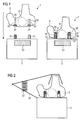
- FIG. 1 shows a hearing device 3 according to the invention and the associated charger 5 in a first position 1 and a second position 2.
- the hearing aid 3 is an IdO, it contains an accumulator 31.
- In its housing two openings with guides 33 and 33 'are provided.
- In the guides are provided as spiral springs resetting elements 35 and 35 'and at the ends thereof are the contact elements 37 and 37'.
- the contact elements 37, 37 ' are movably mounted in the guides 33, 33' and are in the first position (ie in an operating or resting state of the hearing aid without interaction with the charger) in a position wherein the outer surface of the contact element 37, 37 'substantially flush with the housing of the hearing aid 3, so that the openings are covered by the contact elements.
- the charger 5 has two charging contacts 51 and 51 'designed as pins and contains a magnet 53.
- the hearing aid In a second position 2 (i.e., during a charge), the hearing aid is brought into contact with the charger.
- the magnet 53 attracts the accumulator 31 and thus fixes the hearing device 3 on the charging contacts 51, 51 'formed as pins.
- the charging contacts are in electrical connection with the contact elements 37, 37 'of the hearing device, wherein the contact elements 37, 37' in the guides 33, 33 'are recessed and formed as coil springs return elements 35 and 35' are compressed. Due to the magnetic force of the magnet 53 on the one hand and the spring force of the return elements 35, 35 ', the contact elements 37, 37' are pressed under prestress against the charging contacts 51, 51 'of the charger.
- the charging contacts 51, 51 ' which are designed as pins, stuck in the guides 33, 33', a good hold of the hearing aid is ensured on the charger.
- the two charging contacts of the charger and the associated housing openings or guides 33, 33 ' should be different in size or shaped differently to allow only one orientation. It is also conceivable that the charger has a receptacle which is shaped complementary to the hearing aid (not shown).
- the hearing aid 3 shown in FIG. 2 is identical to the hearing aid of the embodiment of FIG. 1.
- the charger 5 has no magnet, but instead a clamp 55 which is contracted by a spring 57, so that the hearing aid 3 can be clamped between the bracket 55 and the charger 5.
- the bracket 55 is greatly simplified and shown schematically.
- FIG. 3 shows a further embodiment of the hearing device 3 and associated charging device 5.
- the hearing aid 3 is shown in a first position 1 (i.e., in an operating or resting state) and in a second position 2 (i.e., in a state of charge).
- the hearing device 3 has a slide switch 34 which is connected via an actuator 36 to the contact elements 37, 37 'designed as contact pins, which are movably mounted in the guides 33, 33'.
- a magnet 53 is provided, which attracts the hearing aid (or the accumulator 31) in a loading position 2.
- the switch 34 is actuated and via the actuator 36, the contact elements 37, 37 'are pushed out of the guides 33, 33', so that they protrude from the hearing aid housing.
- the contact elements 37 of the hearing device 3 designed as contact pins are received by charging contacts 52, 52 'of the charging device 5 in the form of sockets.
- FIG. 4 shows an alternative embodiment of the charging device 5, wherein the hearing device 3 is identical to the hearing device of the embodiment of FIG.
- the charger 5 shown in FIG. 4 has a clamp 55 which is contracted by a spring 57 so that the hearing aid 3 can be clamped between the charger 5 and the clamp 57.
- FIG. 5 shows a further embodiment of a hearing device 3 and a charging device 5, the charging device 5 having a receptacle for an adapter 7, which is adapted to the hearing device 3.
- the hearing aid 3, the adapter 7 and the charger 5 are shown in a first position 1 and a second position 2 (loading position).
- the charging device 5 has charging contacts 52, 52 'which are designed as charging ports and which can receive corresponding contact pins 71, 71' of the adapter 7.
- the contact pins 71, 71 'of the adapter 7 are in the charging position 2 in electrical contact with the contact elements 37, 37' of the hearing aid 3.
- FIG. 6 an alternative embodiment is shown, wherein the arrangement, as described above in connection with Figs. 2 and 4, a clamp 55 which can be contracted by a spring 57, so that the hearing aid 3 between the adapter 7 and the clamp 55 can be clamped.
- FIG. 7 shows a hearing device 3 according to the invention with a further embodiment of a charging device 5 in a first position 1 and a second position 2 (charging position).
- the charger 5 has a receptacle 54 which is adapted to the hearing device 3 and into which the hearing device 3 can be accommodated.
- a flap 58 contains the charging device-side charging contacts 51, 51 ', which are in the charging position 2 in electrical connection with the contact elements 37, 37' of the hearing device 3.
- the flap 58 is articulated by a hinge 59 to the main part of the charger 5 movable.
- the flap 58 may include a closure member (not shown), e.g. a snap closure or a magnetic closure, so that the hearing device 3 is clamped in the closed charger 5 and the contact elements 37, 37 'of the hearing aid device are pressed under pretension against the charging contacts 51, 51' of the charger.
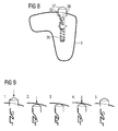
- FIG. 8 shows a further embodiment of the hearing device 3 according to the invention.
- the contact element 37 is designed here as a pin, which is associated with a latching mechanism and a spring element 35.
- the latching mechanism is designed as a latching element 39 and locking lug 38, wherein the latching element 39 can engage in a latching nose 38.
- the hearing aid according to the invention and associated charger can be provided both for in-the-ear hearing aids (IdO) and behind-the-ear hearing aids (BTE).
- the charger may further include a display device, e.g. an LED which indicates the charging status of the hearing aid.
- a display device e.g. an LED which indicates the charging status of the hearing aid.
Abstract
Description
Die Erfindung betrifft ein Hörgerät mit einem beweglichen Kontaktelement, welches mit einem Akkumulator betrieben werden kann.The invention relates to a hearing aid with a movable contact element, which can be operated with an accumulator.
Aufgrund der Entwicklung leistungsfähiger wieder aufladbarer Akkumulator-Batterien ist es möglich, Hörgeräte mit Akkumulator-Batterien auszustatten und zu betreiben. Dabei ergibt sich das Problem, dass der Akkumulator in periodischen Abständen wieder aufgeladen werden muss, was üblicherweise in einem Ladegerät geschieht. Dazu muss üblicherweise der Akkumulator aus dem Gerät entfernt und in dem Ladegerät platziert werden. Da Hörgeräte, insbesondere In-dem-Ohr-Hörgeräte (I-dO), recht klein sind, ist es mühevoll den Akkumulator aus dem Gerät zu entfernen. Dies gilt in besonderem Maß für ältere Hörgeräteträger. Daher wurden im Stand der Technik Hörgeräte entwickelt, welche einen fest eingebauten Akkumulator aufweisen. Damit der Akkumulator im Hörgerät aufgeladen werden kann, ist er so konzipiert, dass er durch Induktion aufgeladen werden kann. Ein derartiges Hörgerät mit induktiv aufladbarem Akkumulator ist z.B. im
Ein durch Induktion aufladbarer Akkumulator ist in der Konstruktion aufwendig und erfordert zusätzlichen, im Hörgerät stets knapp bemessenen Platzbedarf. Das Aufladen durch Induktion erfordert ferner ein aufwendiges Ladegerät und hohen Energieverbrauch.A rechargeable by induction accumulator is complex in construction and requires additional, always tight in the hearing aid space requirements. The charging by induction also requires a complex charger and high energy consumption.
In
Es ist die Aufgabe der vorliegenden Erfindung, ein Hörgerät bereit zu stellen, welches die genannten Nachteile des Standes der Technik behebt.It is the object of the present invention to provide a hearing aid which overcomes the aforementioned disadvantages of the prior art.
Erfindungsgemäß wird die Aufgabe gelöst durch ein Hörgerät gemäß Patentanspruch 1. Vorteilhafte Weiterbildungen des Hörgeräts sind in den abhängigen Patentansprüchen angegeben.According to the invention the object is achieved by a hearing aid according to
Die Erfindung betrifft ein Hörgerät, welches mit einem Akkumulator betrieben werden kann und mindestens ein Kontaktelement aufweist, welches ausgebildet ist, um in elektrischer Verbindung mit einem externen Ladegerät einen Ladestrom aufzunehmen, wobei das Kontaktelement flexibel am Hörgerät angeordnet und bei einem Ladezustand unter Vorspannung an einen Ladekontakt des externen Ladegeräts anpressbar ist.The invention relates to a hearing aid which can be operated with an accumulator and has at least one contact element which is designed to receive a charging current in electrical connection with an external charger, wherein the contact element is arranged flexibly on the hearing aid and under load to a Charging contact of the external charger is pressed.
Bezüglich des Kontaktelements des Hörgerätes sind zwei Situationen zu unterscheiden: ein Betriebs- oder Ruhezustand einerseits, in welchem das Hörgerät nicht aufgeladen wird, und ein Ladezustand andererseits, in welchem das Hörgerät durch das Ladegerät aufgeladen wird. Gemäß der vorliegenden Erfindung befindet sich das Kontaktelement bei einem Betriebs- oder Ruhezustand des Hörgeräts in einer ersten Position und befindet sich bei einem Ladezustand in einer zweiten Position.With respect to the contact element of the hearing aid, two situations are to be distinguished: an operating or resting state on the one hand, in which the hearing aid is not charged, and a state of charge, on the other hand, in which the hearing aid is charged by the charger. In accordance with the present invention, the contact element is in a first position during an operating or resting state of the hearing device and is in a second state in a state of charge.
Der Begriff "Akkumulator" soll im Kontext der vorliegenden Erfindung jegliche wieder aufladbare Batterie, Kondensator o.ä. umfassen, welche wieder aufladbar das Hörgerät mit elektrischer Energie versorgen kann. Das Kontaktelement kann eine Kontaktfläche, ein Kontaktstift, eine Kontaktklemme oder jeglicher anderer Kontakt sein, welcher zur Aufnahme eines Ladestroms geeignet ist. "Flexibel am Hörgerät angeordnet" bedeutet im weitesten Sinne beweglich, flexibel oder deformierbar, so dass das Kontaktelement unter Vorspannung gegen einen entsprechenden Ladekontakt eines externen Ladegeräts, welcher als Widerlager wirkt, anpressbar ist.The term "accumulator" is intended, in the context of the present invention, to mean any rechargeable battery, capacitor, or the like. include, which rechargeable can provide the hearing aid with electrical energy. The contact element may be a contact surface, a contact pin, a contact terminal or any other contact which is suitable for receiving a charging current. "Flexibly arranged on the hearing aid" in the broadest sense means mobile, flexible or deformable, so that the contact element under prestress against a corresponding charging contact of an external charger, which acts as an abutment, can be pressed.
Das Kontaktelement kann so ausgebildet sein, dass es nach Beenden des Ladevorgangs und nach Entfernen des Hörgeräts von dem Ladegerät von der zweiten Position selbsttätig wieder in die erste Position zurückgelangt.The contact element can be designed so that it automatically returns to the first position after completion of the charging process and after removal of the hearing aid from the charger from the second position.
Für das Kontaktelement kann eine entsprechende Öffnung im Gehäuse des Hörgerätes vorgesehen sein. Gemäß einem bevorzugten Aspekt der vorliegenden Erfindung schließt eine Außenfläche des Kontaktelements in der ersten Position (d.h. Betriebs-oder Ruhezustand) im Wesentlichen bündig mit der Gehäuseoberfläche des Hörgerätegehäuses ab. Dies ist ästhetisch ansprechend, sensorisch angenehm und hat den Vorteil, dass dadurch verhindert wird, dass an dieser Stelle Schmutz in das Gehäuseinnere des Hörgeräts gelangt.For the contact element, a corresponding opening may be provided in the housing of the hearing aid. According to a preferred aspect of the present invention, an outer surface of the contact member in the first position (i.e., the operating or resting state) terminates substantially flush with the housing surface of the hearing aid housing. This is aesthetically pleasing, sensory pleasant and has the advantage that this prevents dirt from entering the housing interior of the hearing aid at this point.
Gemäß einem weiteren Aspekt der vorliegenden Erfindung ragt das Kontaktelement in der zweiten Position (d.h. während eines Ladezustands) aus dem Hörgerätegehäuse heraus. Das Kontaktelement kann beispielsweise als Stift ausgebildet sein, welcher beweglich an dem Hörgerät angebracht sein kann, so dass er in der zweiten Position durch eine Öffnung im Hörgerätegehäuse hindurch geschoben werden kann und aus dem Gehäuse herausragt. In diesem Zustand kann das Kontaktelement dann problemlos von dem Ladekontakt des externen Ladegeräts kontaktiert werden.In another aspect of the present invention, in the second position (i.e., during a state of charge), the contact element projects out of the hearing aid housing. The contact element may be formed, for example, as a pin, which may be movably attached to the hearing aid, so that it can be pushed through an opening in the hearing aid housing in the second position and protrudes from the housing. In this state, the contact element can then be easily contacted by the charging contact of the external charger.
Gemäß einem alternativen Aspekt der vorliegenden Erfindung kann das Kontaktelement in die zweite Position in einer Ausnehmung des Hörgerätegehäuses abgesenkt werden. Dies ist vorteilhaft bei einem entsprechenden Ladegerät, welches einen stiftartigen Ladekontakt hat, der dann in die Ausnehmung des Hörgerätegehäuses fassen und das Kontaktelement kontaktieren kann.According to an alternative aspect of the present invention, the contact element can be lowered into the second position in a recess of the hearing aid housing. This is advantageous in a corresponding charger, which has a pin-like charging contact, which can then grasp into the recess of the hearing aid housing and contact the contact element.
Gemäß einem bevorzugten Aspekt der vorliegenden Erfindung ist das Kontaktelement in einer Führungseinrichtung vorgesehen. Diese Führungseinrichtung kann beispielsweise als eine Art Schacht ausgebildet sein, in welcher ein stiftartiges Kontaktelement beweglich geführt ist.According to a preferred aspect of the present invention, the contact element is provided in a guide device. This guide device may be formed, for example, as a kind of shaft in which a pin-like contact element is movably guided.
Gemäß einem weiteren Aspekt der vorliegenden Erfindung ist das Kontaktelement mit einem Federelement und einem Rastmechanismus assoziiert, derart, dass das Kontaktelement durch Drücken von der ersten in die zweite Position und durch Drücken von der zweiten Position in die erste Position bringbar ist. Diese Art von Mechanismus ist der Drucktaste eines Kugelschreibers ähnlich: Durch einmaliges Drücken wird das Kontaktelement von der ersten in die zweite Form überführt, durch nochmaliges Drücken wird es von der zweiten Position in die erste überführt. Dazu kann das Kontaktelement ebenfalls mit einem Rastmechanismus assoziiert sein. Der Rastmechanismus kann integral mit dem Federelement ausgeführt sein oder aus separaten Elementen bestehen. Der Rastmechanismus kann z.B. ein Rastelement, wie z.B. eine Rastzunge, und eine Rastnase aufweisen. Der Rastmechanismus kann einteilig oder mehrteilig sein.According to a further aspect of the present invention, the contact element is associated with a spring element and a latching mechanism, such that the contact element can be brought into the first position by pressing from the first to the second position and by pressing from the second position. This type of mechanism is similar to the pushbutton of a ballpoint pen: By pressing once, the contact element is transferred from the first to the second form, by pressing it again, it is transferred from the second position to the first. For this purpose, the contact element may also be associated with a latching mechanism. The locking mechanism may be integral with the spring element or consist of separate elements. The detent mechanism may e.g. a latching element, such as e.g. a latching tongue, and have a detent. The locking mechanism may be in one piece or in several parts.
Das Kontaktelement kann als Kontaktstift ausgeführt sein.The contact element may be designed as a contact pin.
Gemäß einem bevorzugten Aspekt der vorliegenden Erfindung ist das Kontaktelement mit einem Rückstellelement assoziiert, durch welches das Kontaktelement nach einem Ladevorgang von der zweiten Position in die erste Position zurückgestellt werden kann. Ein derartiges Rückstellelement kann beispielsweise ein elastisch verformbares Element sein, z.B. eine Feder, insbesondere eine Spiralfeder, oder ein elastisch deformierbares Material, z.B. Schaumstoff oder Silikongummi, welcher beim Anordnen des Hörgeräts mit dem Ladegerät deformiert wird und unter Ausübung einer Rückstellkraft das Kontaktelement des Hörgeräts gegen den korrespondierenden Ladekontakt des Ladegeräts anpresst, und bei Entfernen des Hörgeräts von dem Ladegerät das Kontaktelement zurück in die erste Position überführt. Es ist selbstverständlich auch denkbar, dass das Kontaktelement selber gleichzeitig als Rückstellelement fungiert, z.B. indem es als flexible Lasche ausgebildet ist.According to a preferred aspect of the present invention, the contact element is associated with a return element, by means of which the contact element can be reset after a loading operation from the second position to the first position. Such a restoring element may be, for example, an elastically deformable element, for example a spring, in particular a spiral spring, or an elastically deformable material, eg foam or silicone rubber, which is deformed when the hearing device is arranged with the charger and against the contact element of the hearing device by applying a restoring force presses the corresponding charging contact of the charger, and when removing the hearing aid from the charger, the contact element back to the first position transferred. It is of course also conceivable that the contact element itself acts as a restoring element, for example, by being designed as a flexible tab.
Gemäß einem bevorzugten Aspekt der vorliegenden Erfindung weist das Hörgerät ferner einen Schalter auf, wobei das Kontaktelement über den Schalter von der ersten in die zweite Position und umgekehrt überführbar ist. Gemäß einem besonders bevorzugten Aspekt der vorliegenden Erfindung wird der Schalter durch in Kontakt bringen des Hörgeräts mit dem externen Ladegerät betätigt, z.B. bei Einlegen des Hörgeräts in eine dafür vorgesehene Aufnahme im Ladegerät.According to a preferred aspect of the present invention, the hearing device further comprises a switch, wherein the contact element via the switch from the first to the second position and vice versa is feasible. According to a particularly preferred aspect of the present invention, the switch is actuated by contacting the hearing aid with the external charger, e.g. when inserting the hearing aid in a designated recording in the charger.
Für das erfindungsgemäße Hörgerät kann ferner ein Ladegerät vorgesehen sein, wobei ein Kontaktelement des Hörgeräts bei einem Ladezustand unter Vorspannung gegen einen Ladekontakt des Ladegeräts anpressbar ist.For the hearing aid according to the invention may also be provided a charger, wherein a contact element of the hearing aid is pressed in a state of charge under bias against a charging contact of the charger.
Um das Kontaktelement des Hörgeräts gegen den Ladekontakt des Ladegeräts mit Vorspannung anzupressen, kann das Ladegerät ein magnetisches Element aufweisen, wodurch das Hörgerät mit Magnetkraft angepresst werden kann. Beispielsweise kann in dem Ladegerät ein Permanentmagnet oder ein Elektromagnet vorgesehen sein, welcher ein magnetisches Element im Hörgerät, z.B. den Akkumulator, anzieht.To bias the contact element of the hearing aid against the charging contact of the charger with bias, the charger may have a magnetic element, whereby the hearing aid can be pressed with magnetic force. For example, in the charger, a permanent magnet or an electromagnet may be provided, which comprises a magnetic element in the hearing aid, e.g. the accumulator, attracts.
Das Kontaktelement des Hörgeräts kann durch Federkraft mit Vorspannung gegen den Ladekontakt des Hörgeräts angepresst werden, dazu kann das Ladegerät ein entsprechendes Federelement oder Spannelement aufweisen, z.B. eine Klammer, um das Hörgerät einzuspannen.The contact element of the hearing aid can be pressed by spring force with bias against the charging contact of the hearing aid, for this purpose, the charger may have a corresponding spring element or clamping element, e.g. a clamp to clamp the hearing aid.
Das Ladegerät kann eine Aufnahme für das Hörgerät aufweisen, welche durch ihre räumliche Ausgestaltung eine eindeutige Ladeposition des Ladegeräts vorgibt. Die Aufnahme kann an die Form des Hörgeräts angepasst sein. Dazu ist es denkbar, dass die Aufnahme an einen für einen Träger spezifischen Bereich des Hörgeräts angepasst ist (dies gilt insbesondere für IdO) oder die Aufnahme kann an einen nicht für einen Träger spezifischen Bereich des Hörgeräts angepasst sein. Die Aufnahme kann in ihrer Form komplementär zu einer Oberflächenform des Hörgeräts ausgebildet sein.The charger may have a receptacle for the hearing aid, which dictates a unique charging position of the charger by their spatial configuration. The recording can be adapted to the shape of the hearing aid. For this purpose, it is conceivable that the recording is adapted to a region of the hearing device that is specific for a wearer (this applies in particular to IdO). or the recording may be adapted to a non-carrier specific area of the hearing aid. The receptacle may be designed in its shape complementary to a surface shape of the hearing aid.
Ein Adapterelement kann vorgesehen sein, wobei die Aufnahme an das Adapterelement angepasst ist, und das Adapterelement an einen trägerspezifischen Bereich des Hörgeräts angepasst ist. Somit ist es möglich, für eine Vielzahl von individuellen trägerspezifisch geformten Hörgeräten einen einzelnen Ladegerät-Typ herzustellen und jeweils mit einem Adapter auszustatten, welcher an das individuelle Hörgerät angepasst ist.An adapter element can be provided, wherein the receptacle is adapted to the adapter element, and the adapter element is adapted to a carrier-specific region of the hearing device. It is therefore possible to produce a single type of charger for a large number of individual carrier-specific shaped hearing aids and to equip each with an adapter which is adapted to the individual hearing device.
Gemäß einem weiteren Aspekt der vorliegenden Erfindung ist durch die Ladeposition des Hörgeräts in der Aufnahme des Ladegeräts eine korrekte Polung des Ladekontakts vorgegeben.According to a further aspect of the present invention, a correct polarity of the charging contact is predetermined by the charging position of the hearing device in the receptacle of the charging device.
Von der Erfindung selbstverständlich ebenfalls umfasst ist ein Hörgerät mit zwei oder mehr Kontaktelementen (z.B. Plus-und Minuspol), wobei mindestens ein Kontaktelement in der oben beschriebenen Weise flexibel an dem Hörgerät angeordnet ist.A hearing device with two or more contact elements (for example, positive and negative poles), wherein at least one contact element is flexibly arranged on the hearing device in the manner described above, is of course likewise encompassed by the invention.
Weitere Merkmale und Vorteile der vorliegenden Erfindung werden deutlich anhand der Ausführungsbeispiele und angehängten Figuren, in denen zeigen:
- Fig. 1
- eine schematische Darstellung einer ersten Ausführungsform eines erfindungsgemäßen Hörgeräts und zugehörigen Ladegeräts;
- Fig. 2
- eine schematische Darstellung einer zweiten Ausführungsform eines erfindungsgemäßen Hörgeräts und zugehörigen Ladegeräts;
- Fig. 3
- eine schematische Darstellung einer dritten Ausführungsform eines erfindungsgemäßen Hörgeräts und zugehörigen Ladegeräts;
- Fig. 4
- eine schematische Darstellung einer vierten Ausführungsform eines erfindungsgemäßen Hörgeräts und zugehörigen Ladegeräts;
- Fig. 5
- eine schematische Darstellung einer fünften Ausführungsform eines erfindungsgemäßen Hörgeräts und zugehörigen Ladegeräts;
- Fig. 6
- eine schematische Darstellung einer sechsten Ausführungsform eines erfindungsgemäßen Hörgeräts und zugehörigen Ladegeräts;
- Fig. 7
- eine schematische Darstellung einer siebten Ausführungsform eines erfindungsgemäßen Hörgeräts und zugehörigen Ladegeräts;
- Fig. 8
- eine schematische Darstellung einer achten Ausführungsform eines erfindungsgemäßen Hörgeräts;
- Fig. 9
- eine schematische Darstellung der Funktionsweise der Ausführungsform gemäß Fig. 8.
- Fig. 1
- a schematic representation of a first embodiment of a hearing aid according to the invention and associated charger;
- Fig. 2
- a schematic representation of a second embodiment of a hearing aid according to the invention and associated charger;
- Fig. 3
- a schematic representation of a third embodiment of a hearing aid according to the invention and associated charger;
- Fig. 4
- a schematic representation of a fourth embodiment of a hearing aid according to the invention and associated charger;
- Fig. 5
- a schematic representation of a fifth embodiment of a hearing aid according to the invention and associated charger;
- Fig. 6
- a schematic representation of a sixth embodiment of a hearing aid according to the invention and associated charger;
- Fig. 7
- a schematic representation of a seventh embodiment of a hearing aid according to the invention and associated charger;
- Fig. 8
- a schematic representation of an eighth embodiment of a hearing aid according to the invention;
- Fig. 9
- a schematic representation of the operation of the embodiment of FIG. 8.
In Figur 1 ist ein erfindungsgemäßes Hörgerät 3 und zugehöriges Ladegerät 5 in einer ersten Position 1 und einer zweiten Position 2 gezeigt. Das Hörgerät 3 ist ein IdO, es enthält einen Akkumulator 31. In seinem Gehäuse sind zwei Öffnungen mit Führungen 33 bzw. 33' vorgesehen. In den Führungen befinden sich als Spiralfedern ausgeführte Rückstellelemente 35 bzw. 35' und an deren Enden sind die Kontaktelemente 37 bzw. 37'. Die Kontaktelemente 37, 37' sind in den Führungen 33, 33' beweglich angebracht und befinden sich in der ersten Position (d.h. bei einem Betriebs- oder Ruhezustand des Hörgeräts ohne Wechselwirkung mit dem Ladegerät) in einer Position, wobei die Außenfläche des Kontaktelements 37, 37' im Wesentlichen bündig mit dem Gehäuse des Hörgeräts 3, so dass die Öffnungen durch die Kontaktelemente abgedeckt werden.FIG. 1 shows a
Dies verhindert vorteilhaft, dass Cerumen oder Schmutz in das Hörgerät gelangt. Das Ladegerät 5 weist zwei als Stifte ausgebildete Ladekontakte 51 bzw. 51' auf und enthält einen Magneten 53.This advantageously prevents cerumen or dirt from entering the hearing aid. The
In einer zweiten Position 2 (d.h. während eines Ladevorgangs) wird das Hörgerät mit dem Ladegerät in Kontakt gebracht. Der Magnet 53 zieht den Akkumulator 31 an und fixiert so das Hörgerät 3 auf den als Stifte ausgebildeten Ladekontakten 51, 51'. Die Ladekontakte sind mit den Kontaktelementen 37, 37' des Hörgeräts in elektrischer Verbindung, wobei die Kontaktelemente 37, 37' in den Führungen 33, 33' versenkt sind und die als Spiralfedern ausgebildeten Rückstellelemente 35 und 35' zusammengedrückt sind. Durch die magnetische Kraft des Magneten 53 einerseits und die Federkraft der Rückstellelemente 35, 35' werden die Kontaktelemente 37, 37' unter Vorspannung an die Ladekontakte 51, 51' des Ladegeräts angepresst.In a second position 2 (i.e., during a charge), the hearing aid is brought into contact with the charger. The
Dadurch, dass die Ladekontakte 51, 51', welche als Stifte ausgebildet sind, in den Führungen 33, 33' stecken, wird ein guter Halt des Hörgeräts an dem Ladegerät gewährleistet. Um eine falsche Polung der Kontakte zu verhindern, sollten die beiden Ladekontakte des Ladegerätes und die zugehörigen Gehäuseöffnungen bzw. Führungen 33, 33' unterschiedlich groß sein oder unterschiedlich geformt sein, um nur eine Ausrichtung zuzulassen. Ebenso ist es denkbar, dass das Ladegerät eine Aufnahme aufweist, welche komplementär zu dem Hörgerät geformt ist (nicht gezeigt).The fact that the charging
Das in Fig. 2 gezeigte Hörgerät 3 ist mit dem Hörgerät der Ausführungsform von Fig. 1 identisch. Das Ladegerät 5 weist jedoch keinen Magneten auf, sondern anstatt dessen eine Klammer 55, welche von einer Feder 57 zusammengezogen wird, so dass das Hörgerät 3 zwischen der Klammer 55 und dem Ladegerät 5 eingespannt werden kann. Es wird darauf hingewiesen, dass die Klammer 55 stark vereinfacht und schematisch dargestellt ist.The
In Fig. 3 ist eine weitere Ausführungsform des Hörgeräts 3 und zugehörigen Ladegeräts 5 dargestellt. Das Hörgerät 3 ist in einer ersten Position 1 (d.h. in einem Betriebs- oder Ruhezustand) und in einer zweiten Position 2 (d.h. in einem Ladezustand) gezeigt. Das Hörgerät 3 weist einen Schiebeschalter 34 auf, welcher über ein Stellglied 36 mit den als Kontaktstiften ausgebildeten Kontaktelementen 37, 37' in Verbindung ist, welche in den Führungen 33, 33' beweglich gelagert sind. In dem Ladegerät 5 ist ein Magnet 53 vorgesehen, welcher in einer Ladeposition 2 das Hörgerät (bzw. den Akkumulator 31) anzieht. Dadurch wird der Schalter 34 betätigt und über das Stellglied 36 werden die Kontaktelemente 37, 37' aus den Führungen 33, 33' herausgeschoben, so dass sie aus dem Hörgerätgehäuse herausragen. In der zweiten Position 2 werden die als Kontaktstifte ausgebildeten Kontaktelemente 37 des Hörgeräts 3 von als Buchsen ausgebildeten Ladekontakten 52, 52' des Ladegeräts 5 aufgenommen.FIG. 3 shows a further embodiment of the
In Fig.4 ist eine alternative Ausführungsform des Ladegeräts 5 gezeigt, wobei das Hörgerät 3 identisch zu dem Hörgerät der Ausführungsform von Figur 3 ist. Das in Figur 4 gezeigte Ladegerät 5 weist wie bereits oben bei Fig. 2 beschrieben eine Klammer 55 auf, welche durch eine Feder 57 zusammengezogen wird, so dass das Hörgerät 3 zwischen dem Ladegerät 5 und der Klammer 57 eingespannt werden kann.FIG. 4 shows an alternative embodiment of the
In Fig. 5 ist eine weitere Ausführungsform eines Hörgeräts 3 und eines Ladegeräts 5 gezeigt, wobei das Ladegerät 5 eine Aufnahme für einen Adapter 7 aufweist, welches an das Hörgerät 3 angepasst ist. Das Hörgerät 3, der Adapter 7 und das Ladegerät 5 sind in einer ersten Position 1 und einer zweiten Position 2 (Ladeposition) gezeigt. Das Ladegerät 5 weist als Ladebuxen ausgebildete Ladekontakte 52, 52' auf, welche entsprechende Kontaktstifte 71, 71' des Adapters 7 aufnehmen können. Die Kontaktstifte 71, 71' des Adapters 7 sind in der Ladeposition 2 in elektrischem Kontakt mit den Kontaktelementen 37, 37' des Hörgeräts 3. Durch einen Magneten 53 im Ladegerät wird der Akku 31 des Hörgeräts 3 angezogen, so dass die Kontaktelemente 37, 37' über die Kontaktstifte 71, 71' des Adapters 7 an die Ladekontakte 52, 52' des Ladegeräts 5 unter Vorspannung angepresst werden.FIG. 5 shows a further embodiment of a
In Fig. 6 ist eine alternative Ausführungsform gezeigt, wobei die Anordnung, wie oben in Zusammenhang mit Fig. 2 und 4 beschrieben, eine Klammer 55 aufweist, welche durch eine Feder 57 zusammengezogen werden kann, so dass das Hörgerät 3 zwischen dem Adapter 7 und der Klammer 55 eingespannt werden kann.In Fig. 6, an alternative embodiment is shown, wherein the arrangement, as described above in connection with Figs. 2 and 4, a
In Fig. 7 ist ein erfindungsgemäßes Hörgerät 3 mit einer weiteren Ausführungsform eines Ladegeräts 5 in einer ersten Position 1 und einer zweiten Position 2 (Ladeposition) gezeigt. Das Ladegerät 5 weist eine an das Hörgerät 3 angepasste Aufnahme 54 auf, in welche das Hörgerät 3 aufgenommen werden kann. Eine Klappe 58 enthält die Ladegerät-seitigen Ladekontakte 51, 51', welche in der Ladeposition 2 in elektrischer Verbindung mit den Kontaktelementen 37, 37' des Hörgeräts 3 sind. Die Klappe 58 ist mit einem Scharnier 59 an den Hauptteil des Ladegeräts 5 beweglich angelenkt. Die Klappe 58 kann ein Verschlusselement aufweisen (nicht gezeigt), z.B. einen Schnappverschluss oder einen magnetischen Verschluss, so dass das Hörgerät 3 in dem geschlossenen Ladegerät 5 eingespannt ist und die Kontaktelemente 37, 37' des Ladehörgeräts unter Vorspannung gegen die Ladekontakte 51, 51' des Ladegeräts angepresst werden.FIG. 7 shows a
In Figur 8 ist eine weitere Ausführungsform des erfindungsgemäßen Hörgeräts 3 dargestellt. Das Kontaktelement 37 ist hier als Stift ausgeführt, der mit einem Rastmechanismus und einem Federelement 35 assoziiert ist. Der Rastmechanismus ist als Rastelement 39 und Rastnase 38 ausgeführt, wobei das Rastelement 39 in eine Rastnase 38 einrasten kann. Ähnlich der Drucktaste eines Kugelschreibers kann der Kontaktstift 37 durch drücken von der ersten in die zweite Position und zurück überführt werden, was in Fig. 9 schematisch dargestellt ist: 1. Der Kontaktstift wird nach unten gedrückt; 2. der Kontaktstift wird im Hörgerät versenkt (= Betriebsposition); 3. das Rastelement hält den Kontaktstift in Position; 4. erneutes Drücken löst die Rastung , der Kontaktstift bewegt sich nach oben aus dem Gehäuse heraus; 5. das Kontaktelement steht aus dem Gehäuse hervor (Ladeposition) und ist federnd gelagert.FIG. 8 shows a further embodiment of the
Es ist vorgesehen, dass das erfindungsgemäße Hörgerät und zugehörige Ladegerät sowohl für in-dem-Ohr-Hörgeräte (IdO) als auch Hinter-dem-Ohr-Hörgeräte (HdO) vorgesehen sein kann. Das Ladegerät kann ferner eine Anzeigevorrichtung aufweisen, z.B. eine LED, welche den Ladestatus des Hörgeräts anzeigt. Um das Hörgerät während des Ladevorgangs in einem Lade-Betriebszustand zu schalten, könnte der Betriebsstrom beim Einsetzen des Hörgeräts über die Ladekontakte auf einen bestimmten Pegel gezogen werden, wodurch ein Lademodus ausgelöst wird. Ferner ist es denkbar, dass nach erfolgreichem Laden und Entnahme aus dem Ladegerät das Hörgerät dann mittels Fernbedienung wieder eingeschaltet werden kann.It is envisaged that the hearing aid according to the invention and associated charger can be provided both for in-the-ear hearing aids (IdO) and behind-the-ear hearing aids (BTE). The charger may further include a display device, e.g. an LED which indicates the charging status of the hearing aid. In order to switch the hearing aid in a charging operating state during the charging process, the operating current when inserting the hearing aid via the charging contacts could be pulled to a certain level, whereby a charging mode is triggered. Further, it is conceivable that after successful loading and removal from the charger, the hearing aid can then be turned on again by remote control.
Die dargestellten Ausführungsbeispiele sollen lediglich veranschaulichend und beispielhaft sein. Bezüglich der Anordnung von Hörgerät, Ladegerät und den entsprechenden Kontaktelementen und Ladekontakten sind im Rahmen des durch die Patentansprüche bestimmten Umfangs Änderungen und Variationen möglich.The illustrated embodiments are merely illustrative and exemplary. With regard to the arrangement of the hearing aid, charger and the corresponding contact elements and charging contacts, changes and variations are possible within the scope of the claims.
Claims (10)
Applications Claiming Priority (1)
| Application Number | Priority Date | Filing Date | Title |
|---|---|---|---|
| DE102006052713A DE102006052713A1 (en) | 2006-11-08 | 2006-11-08 | Hearing aid and associated charger |
Publications (2)
| Publication Number | Publication Date |
|---|---|
| EP1921893A2 true EP1921893A2 (en) | 2008-05-14 |
| EP1921893A3 EP1921893A3 (en) | 2011-06-29 |
Family
ID=39015867
Family Applications (2)
| Application Number | Title | Priority Date | Filing Date |
|---|---|---|---|
| EP07119851A Withdrawn EP1921894A3 (en) | 2006-11-08 | 2007-11-02 | Charging device for a hearing aid |
| EP07021423A Withdrawn EP1921893A3 (en) | 2006-11-08 | 2007-11-02 | Hearing aid and corresponding charging device |
Family Applications Before (1)
| Application Number | Title | Priority Date | Filing Date |
|---|---|---|---|
| EP07119851A Withdrawn EP1921894A3 (en) | 2006-11-08 | 2007-11-02 | Charging device for a hearing aid |
Country Status (3)
| Country | Link |
|---|---|
| US (2) | US8027497B2 (en) |
| EP (2) | EP1921894A3 (en) |
| DE (1) | DE102006052713A1 (en) |
Cited By (7)
| Publication number | Priority date | Publication date | Assignee | Title |
|---|---|---|---|---|
| EP2299731A1 (en) * | 2009-09-21 | 2011-03-23 | Oticon A/S | A listening device with a rechargeable energy source adapted for being charged through an ite-unit or a connector connectable to a bte-unit |
| CN102026081A (en) * | 2009-09-21 | 2011-04-20 | 奥迪康有限公司 | Listening device with a rechargeable energy source |
| EP2461429A1 (en) | 2010-12-01 | 2012-06-06 | Legrand France | Power socket and electric plug provided with means for magnetic attraction |
| WO2014198324A1 (en) * | 2013-06-13 | 2014-12-18 | Phonak Ag | A rechargable hearing device, a battery charger for charging such a hearing device, and a method of charging such a hearing device |
| US8958590B2 (en) | 2009-09-21 | 2015-02-17 | Oticon A/S | Listening device with a rechargeable energy source adapted for being charged through an ITE-unit, or a connector connectable to, or a connector of, a BTE-unit |
| WO2020264354A1 (en) * | 2019-06-26 | 2020-12-30 | Starkey Laboratories, Inc. | Hearing instrument and charger |
| WO2021258312A1 (en) * | 2020-06-24 | 2021-12-30 | Harman Becker Automotive Systems Gmbh | Earbuds with improved alignment of electrodes |
Families Citing this family (33)
| Publication number | Priority date | Publication date | Assignee | Title |
|---|---|---|---|---|
| DE102006052712A1 (en) * | 2006-11-08 | 2008-05-15 | Siemens Audiologische Technik Gmbh | Rechargeable hearing aid and associated charger |
| DK2026602T3 (en) * | 2007-07-30 | 2012-01-16 | Siemens Medical Instr Pte Ltd | Hearing aid with movable charging connector |
| DE102007042324B4 (en) * | 2007-09-06 | 2012-08-30 | Siemens Medical Instruments Pte. Ltd. | In-the-ear hearing aid with contact means and associated battery charger |
| DE102007061866A1 (en) * | 2007-12-19 | 2009-06-25 | Bergert & Maniewski GbR (vertretungsberechtigter Gesellschafter: Jonas Bergert, 52070 Aachen) | Charging device for mobile handset, has magnet e.g. permanent magnet, formed for connection between charging device and mobile hand set, where magnet is formed as part of charging device |
| EP2424275B1 (en) | 2010-08-30 | 2019-10-09 | Oticon A/S | A listening device adapted for establishing an electric connection to an external device using electrically conductive parts of one or more components of the listening device |
| KR101246878B1 (en) * | 2011-02-11 | 2013-03-25 | (주)에스피에스 | Charging device using magnet |
| CN103781562B (en) | 2011-08-05 | 2017-08-01 | Gui环球产品有限公司 | For cleaning the equipment and its application method of screen and lens |
| DE102012218663A1 (en) * | 2012-10-12 | 2014-04-17 | Audia Akustik Gmbh | Charging cradle for charging accumulator in hearing device, has secondary coil that is arranged in charging cradle for receiving electrical energy from primary coil arranged in charging mat |
| US20200137906A9 (en) | 2012-11-05 | 2020-04-30 | Gui Global Products, Ltd. | Devices and accessories employing a living hinge |
| CN203589347U (en) * | 2013-06-04 | 2014-05-07 | M·W·保卢斯 | Magnetic mounting system used for integrated conduction type charging of electronic equipment |
| US20160165367A1 (en) * | 2013-07-22 | 2016-06-09 | Sonova Ag | A rechargeable hearing device and a battery charger for charging the hearing device |
| EP2840355A1 (en) * | 2013-08-21 | 2015-02-25 | HILTI Aktiengesellschaft | Laser device and fixing device for mounting a laser device on a retaining element |
| WO2015039707A1 (en) | 2013-09-23 | 2015-03-26 | Phonak Ag | A rechargable hearing device, a hearing device charging system and a method for charging a hearing device |
| US10039322B2 (en) * | 2013-09-27 | 2018-08-07 | Altria Client Services Llc | Electronic smoking article |
| US9148717B2 (en) * | 2014-02-21 | 2015-09-29 | Alpha Audiotronics, Inc. | Earbud charging case |
| US8891800B1 (en) * | 2014-02-21 | 2014-11-18 | Jonathan Everett Shaffer | Earbud charging case for mobile device |
| MX361274B (en) * | 2014-06-18 | 2018-12-03 | Zpower Llc | Voltage regulator and control circuit for silver-zinc batteries in hearing instruments. |
| AU2015277299B2 (en) | 2014-06-18 | 2019-09-19 | Zpower, Llc | Hearing aid battery door module |
| DK3151582T3 (en) | 2015-09-30 | 2020-10-12 | Apple Inc | HEADPHONE WITH CHARGING SYSTEM CASE |
| CN106806047A (en) * | 2015-11-27 | 2017-06-09 | 英业达科技有限公司 | Ear-hang device for preventing snoring and snore relieving system |
| CN107623889A (en) * | 2016-07-13 | 2018-01-23 | 深圳市中德听力技术有限公司 | A kind of rechargeable hearing aid |
| US10873203B2 (en) * | 2017-03-31 | 2020-12-22 | Flir Commercial Systems, Inc. | Systems and methods for wireless charging of devices |
| EP3518560B1 (en) | 2018-01-30 | 2020-11-04 | Sonova AG | Adaptable hearing device charging port for a hearing device charger |
| US11172101B1 (en) | 2018-09-20 | 2021-11-09 | Apple Inc. | Multifunction accessory case |
| RU2693528C1 (en) * | 2018-12-11 | 2019-07-03 | Общество с ограниченной ответственностью "Исток Аудио" | Hearing aid housing |
| RU189031U1 (en) * | 2019-02-26 | 2019-05-07 | Общество с ограниченной ответственностью "Исток Аудио" (ООО "Исток Аудио") | CHARGER DEVICE FOR THE HEARING EQUIPMENT |
| US10798500B1 (en) * | 2019-05-30 | 2020-10-06 | Xiamen Retone Hearing Technology Co., Ltd. | Behind-the-ear hearing aid |
| EP3796441A1 (en) | 2019-09-18 | 2021-03-24 | Sivantos Pte. Ltd. | Battery charger for charging a wearable audio device |
| US11582566B2 (en) | 2019-12-02 | 2023-02-14 | Gn Hearing A/S | Hearing instrument charger device and system, and a method of manufacturing a holder therefor |
| US10993045B1 (en) * | 2020-03-30 | 2021-04-27 | Sonova Ag | Hearing devices and methods for implementing automatic sensor-based on/off control of a hearing device |
| US11765525B2 (en) * | 2020-12-11 | 2023-09-19 | Gn Hearing A/S | Hearing instrument charger device and system, and a method of manufacturing a holder therefor |
| DK202170010A1 (en) * | 2021-01-08 | 2022-08-11 | Gn Hearing As | A charging kit for charging one or more rechargeable hearing devices |
| US11595767B1 (en) | 2021-11-18 | 2023-02-28 | Sonova Ag | Rechargeable hearing devices and chargers for use with same |
Citations (5)
| Publication number | Priority date | Publication date | Assignee | Title |
|---|---|---|---|---|
| DE1870845U (en) * | 1962-11-12 | 1963-04-25 | Danavox As | ELECTRIC HOUSEHOLD DEVICE WITH CHARGER. |
| US4539439A (en) * | 1983-04-18 | 1985-09-03 | Unitron Industries Ltd. | Plugs, receptacles and hearing aids |
| US5253300A (en) * | 1991-03-22 | 1993-10-12 | H. C. Knapp Sound Technology Inc. | Solar powered hearing aid |
| EP0630549A1 (en) * | 1992-03-13 | 1994-12-28 | Audiologie Prothese Innovation | Device for recharging an intra-auricular prosthesis battery and process for the manufacture of said device. |
| WO1999029009A1 (en) * | 1997-11-27 | 1999-06-10 | 'jaguar' Stahlwarenfabrik Gmbh & Co. Kg | Charging station for chargeable hand-held electrical apparatus |
Family Cites Families (5)
| Publication number | Priority date | Publication date | Assignee | Title |
|---|---|---|---|---|
| US4186335A (en) * | 1977-09-21 | 1980-01-29 | Cahill Enterprises, Inc. | Hearing aid battery recharging apparatus |
| US5754124A (en) * | 1996-11-13 | 1998-05-19 | Pittco, Inc. | Electrical hazard warning system |
| DE29718104U1 (en) * | 1997-10-14 | 1998-01-02 | Audia Akustik Gmbh | Charging device for hearing aids |
| US6326766B1 (en) * | 2000-06-09 | 2001-12-04 | Shoot The Moon Products Ii, Llc | Rechargable battery pack and battery pack charger with safety mechanisms |
| US6498455B2 (en) * | 2001-02-22 | 2002-12-24 | Gary Skuro | Wireless battery charging system for existing hearing aids using a dynamic battery and a charging processor unit |
-
2006
- 2006-11-08 DE DE102006052713A patent/DE102006052713A1/en not_active Withdrawn
-
2007
- 2007-11-01 US US11/933,491 patent/US8027497B2/en active Active
- 2007-11-02 EP EP07119851A patent/EP1921894A3/en not_active Withdrawn
- 2007-11-02 EP EP07021423A patent/EP1921893A3/en not_active Withdrawn
- 2007-11-08 US US11/983,341 patent/US20080136369A1/en not_active Abandoned
Patent Citations (5)
| Publication number | Priority date | Publication date | Assignee | Title |
|---|---|---|---|---|
| DE1870845U (en) * | 1962-11-12 | 1963-04-25 | Danavox As | ELECTRIC HOUSEHOLD DEVICE WITH CHARGER. |
| US4539439A (en) * | 1983-04-18 | 1985-09-03 | Unitron Industries Ltd. | Plugs, receptacles and hearing aids |
| US5253300A (en) * | 1991-03-22 | 1993-10-12 | H. C. Knapp Sound Technology Inc. | Solar powered hearing aid |
| EP0630549A1 (en) * | 1992-03-13 | 1994-12-28 | Audiologie Prothese Innovation | Device for recharging an intra-auricular prosthesis battery and process for the manufacture of said device. |
| WO1999029009A1 (en) * | 1997-11-27 | 1999-06-10 | 'jaguar' Stahlwarenfabrik Gmbh & Co. Kg | Charging station for chargeable hand-held electrical apparatus |
Cited By (10)
| Publication number | Priority date | Publication date | Assignee | Title |
|---|---|---|---|---|
| EP2299731A1 (en) * | 2009-09-21 | 2011-03-23 | Oticon A/S | A listening device with a rechargeable energy source adapted for being charged through an ite-unit or a connector connectable to a bte-unit |
| CN102026081A (en) * | 2009-09-21 | 2011-04-20 | 奥迪康有限公司 | Listening device with a rechargeable energy source |
| EP2466912A1 (en) * | 2009-09-21 | 2012-06-20 | Oticon A/S | Listening device with a rechargeable energy source adapted for being charged through an ITE-unit, use and method of manufacturing thereof |
| US8462972B2 (en) | 2009-09-21 | 2013-06-11 | Oticon A/S | Listening device with a rechargeable energy source adapted for being charged through an ITE-unit, or a connector connectable to, or a connector of, a BTE-unit |
| US8958590B2 (en) | 2009-09-21 | 2015-02-17 | Oticon A/S | Listening device with a rechargeable energy source adapted for being charged through an ITE-unit, or a connector connectable to, or a connector of, a BTE-unit |
| EP2461429A1 (en) | 2010-12-01 | 2012-06-06 | Legrand France | Power socket and electric plug provided with means for magnetic attraction |
| FR2968467A1 (en) * | 2010-12-01 | 2012-06-08 | Legrand France | POWER SOCKET AND ELECTRICAL PLUG EQUIPPED WITH MEANS OF MAGNETIC ATTRACTION |
| WO2014198324A1 (en) * | 2013-06-13 | 2014-12-18 | Phonak Ag | A rechargable hearing device, a battery charger for charging such a hearing device, and a method of charging such a hearing device |
| WO2020264354A1 (en) * | 2019-06-26 | 2020-12-30 | Starkey Laboratories, Inc. | Hearing instrument and charger |
| WO2021258312A1 (en) * | 2020-06-24 | 2021-12-30 | Harman Becker Automotive Systems Gmbh | Earbuds with improved alignment of electrodes |
Also Published As
| Publication number | Publication date |
|---|---|
| EP1921894A3 (en) | 2011-06-29 |
| US20080118093A1 (en) | 2008-05-22 |
| EP1921893A3 (en) | 2011-06-29 |
| EP1921894A2 (en) | 2008-05-14 |
| US20080136369A1 (en) | 2008-06-12 |
| US8027497B2 (en) | 2011-09-27 |
| DE102006052713A1 (en) | 2008-05-15 |
Similar Documents
| Publication | Publication Date | Title |
|---|---|---|
| EP1921893A2 (en) | Hearing aid and corresponding charging device | |
| EP2285136B1 (en) | Hearing aid with replaceable earpiece | |
| EP2323197A2 (en) | Battery with holder device | |
| DE60103934T2 (en) | COMMUNICATIONS DEVICE | |
| DE102012104538A1 (en) | Tool | |
| EP2523282B1 (en) | Central disc of an electric installation device for depositing and electrically charging a mobile audio and communication device | |
| EP2529463A2 (en) | Restart protection for battery-powered electrical appliances | |
| DE102009004006B3 (en) | Battery compartment with locking element for a behind-the-ear hearing aid | |
| DE102007061866A1 (en) | Charging device for mobile handset, has magnet e.g. permanent magnet, formed for connection between charging device and mobile hand set, where magnet is formed as part of charging device | |
| DE102008008670A1 (en) | Charger for a hearing device with a movable charging contact | |
| CH673919A5 (en) | ||
| EP2144456A1 (en) | Hearing aid with lockable battery chamber | |
| DE102011081958A1 (en) | Hearing device e.g. hearing aid has operating element movable in interior of housing, for unlocking locking unit of battery compartment | |
| EP0486788B1 (en) | Accumulator | |
| DE102010055395A1 (en) | Schlüsselkarterschalter | |
| EP2592849B1 (en) | Hearing aid with a battery compartment | |
| WO2003077514A1 (en) | Hands-free device for operating mobile telephones in motor vehicles with a module-changing mechanism | |
| EP1921895A1 (en) | Rechargeable hearing aid | |
| DE102007037027A1 (en) | Hearing device for use with battery charger for charging of rechargeable battery, has frame and contact elements, which are arranged inside and outside shell elements | |
| EP2537197B1 (en) | Energy supply unit for an electric device | |
| EP2375783B1 (en) | Hearing device with audio shoe | |
| DE202015100872U1 (en) | Battery pack and electrical tool | |
| EP2073573B1 (en) | Energy saving module holding device with covered charging contacts and casing module | |
| EP2808852B1 (en) | Remote control | |
| DE102012015668A1 (en) | ID-transmitter for active and/or passive opening and/or closing tailgate and/or door of motor car, has circuit board arranged in housing, and comprising recess, which retains separable U-shaped battery box that includes guide elements |
Legal Events
| Date | Code | Title | Description |
|---|---|---|---|
| PUAI | Public reference made under article 153(3) epc to a published international application that has entered the european phase |
Free format text: ORIGINAL CODE: 0009012 |
|
| AK | Designated contracting states |
Kind code of ref document: A2 Designated state(s): AT BE BG CH CY CZ DE DK EE ES FI FR GB GR HU IE IS IT LI LT LU LV MC MT NL PL PT RO SE SI SK TR |
|
| AX | Request for extension of the european patent |
Extension state: AL BA HR MK RS |
|
| PUAL | Search report despatched |
Free format text: ORIGINAL CODE: 0009013 |
|
| AK | Designated contracting states |
Kind code of ref document: A3 Designated state(s): AT BE BG CH CY CZ DE DK EE ES FI FR GB GR HU IE IS IT LI LT LU LV MC MT NL PL PT RO SE SI SK TR |
|
| AX | Request for extension of the european patent |
Extension state: AL BA HR MK RS |
|
| 17P | Request for examination filed |
Effective date: 20111227 |
|
| AKX | Designation fees paid |
Designated state(s): AT BE BG CH CY CZ DE DK EE ES FI FR GB GR HU IE IS IT LI LT LU LV MC MT NL PL PT RO SE SI SK TR |
|
| 17Q | First examination report despatched |
Effective date: 20130502 |
|
| RAP1 | Party data changed (applicant data changed or rights of an application transferred) |
Owner name: SIVANTOS GMBH |
|
| 18D | Application deemed to be withdrawn |
Effective date: 20151208 |
|
| STAA | Information on the status of an ep patent application or granted ep patent |
Free format text: STATUS: THE APPLICATION IS DEEMED TO BE WITHDRAWN |
|
| R18D | Application deemed to be withdrawn (corrected) |
Effective date: 20151209 |