EP1921868A2 - Method and apparatus for modulating particular light source used for laser display - Google Patents
Method and apparatus for modulating particular light source used for laser display Download PDFInfo
- Publication number
- EP1921868A2 EP1921868A2 EP07120146A EP07120146A EP1921868A2 EP 1921868 A2 EP1921868 A2 EP 1921868A2 EP 07120146 A EP07120146 A EP 07120146A EP 07120146 A EP07120146 A EP 07120146A EP 1921868 A2 EP1921868 A2 EP 1921868A2
- Authority
- EP
- European Patent Office
- Prior art keywords
- laser
- light
- light source
- pixel
- modulating
- Prior art date
- Legal status (The legal status is an assumption and is not a legal conclusion. Google has not performed a legal analysis and makes no representation as to the accuracy of the status listed.)
- Ceased
Links
- 238000000034 method Methods 0.000 title claims abstract description 15
- 239000004065 semiconductor Substances 0.000 claims abstract description 14
- 230000000694 effects Effects 0.000 description 2
- 238000006243 chemical reaction Methods 0.000 description 1
- 230000003287 optical effect Effects 0.000 description 1
Images


Classifications
-
- G—PHYSICS
- G02—OPTICS
- G02B—OPTICAL ELEMENTS, SYSTEMS OR APPARATUS
- G02B26/00—Optical devices or arrangements for the control of light using movable or deformable optical elements
- G02B26/08—Optical devices or arrangements for the control of light using movable or deformable optical elements for controlling the direction of light
- G02B26/10—Scanning systems
-
- H—ELECTRICITY
- H04—ELECTRIC COMMUNICATION TECHNIQUE
- H04N—PICTORIAL COMMUNICATION, e.g. TELEVISION
- H04N9/00—Details of colour television systems
- H04N9/12—Picture reproducers
- H04N9/31—Projection devices for colour picture display, e.g. using electronic spatial light modulators [ESLM]
- H04N9/3129—Projection devices for colour picture display, e.g. using electronic spatial light modulators [ESLM] scanning a light beam on the display screen
-
- G—PHYSICS
- G03—PHOTOGRAPHY; CINEMATOGRAPHY; ANALOGOUS TECHNIQUES USING WAVES OTHER THAN OPTICAL WAVES; ELECTROGRAPHY; HOLOGRAPHY
- G03B—APPARATUS OR ARRANGEMENTS FOR TAKING PHOTOGRAPHS OR FOR PROJECTING OR VIEWING THEM; APPARATUS OR ARRANGEMENTS EMPLOYING ANALOGOUS TECHNIQUES USING WAVES OTHER THAN OPTICAL WAVES; ACCESSORIES THEREFOR
- G03B21/00—Projectors or projection-type viewers; Accessories therefor
- G03B21/14—Details
- G03B21/20—Lamp housings
- G03B21/2006—Lamp housings characterised by the light source
- G03B21/2033—LED or laser light sources
-
- H—ELECTRICITY
- H04—ELECTRIC COMMUNICATION TECHNIQUE
- H04N—PICTORIAL COMMUNICATION, e.g. TELEVISION
- H04N9/00—Details of colour television systems
- H04N9/12—Picture reproducers
- H04N9/31—Projection devices for colour picture display, e.g. using electronic spatial light modulators [ESLM]
- H04N9/3141—Constructional details thereof
- H04N9/315—Modulator illumination systems
- H04N9/3161—Modulator illumination systems using laser light sources
-
- H—ELECTRICITY
- H04—ELECTRIC COMMUNICATION TECHNIQUE
- H04N—PICTORIAL COMMUNICATION, e.g. TELEVISION
- H04N9/00—Details of colour television systems
- H04N9/12—Picture reproducers
- H04N9/31—Projection devices for colour picture display, e.g. using electronic spatial light modulators [ESLM]
- H04N9/3197—Projection devices for colour picture display, e.g. using electronic spatial light modulators [ESLM] using light modulating optical valves
Definitions
- the present invention relates to a method and apparatus for modulating a particular light source used for laser display, and more particularly, to an apparatus and method for converting tunable laser light into a green light source using quasi-phase-matching second-harmonic generation (QPM-SHG) and modulating the laser light into a stable laser display light source using digital modulation.
- QPM-SHG quasi-phase-matching second-harmonic generation
- Laser display is expressed by using a method of modulating the outputs of a blue laser, a green laser, and a red laser according to the scan period of a scan mirror.
- microminiature and low-power laser displays which can be easily carried, have become popular.
- tri-color light sources which are modulated to a level of 20 MHz when video graphics array (VGA) images are displayed, are required.
- semiconductor lasers have implemented modulation light sources for blue and red.
- QPM-SHG Quasi-Phase-Matching Second-Harmonic Generation
- the present invention provides a method and apparatus for providing digital on/off modulation, by which output light of a semiconductor laser is modulated to a frequency that is much higher than an actually required repetition frequency of 20 MHz and a high-speed pulse is inserted into the modulated output light.
- an apparatus for modulating a particular light source for laser display includes a digital modulator digitally modulating light output from a semiconductor laser to a frequency higher than a repetition frequency required for laser image display, and a pixel brightness adjustor inserting at least one high-speed pulse into a period of the modulated output light, which is required for a single pixel, and adjusting a brightness of the pixel by adjusting the number of the inserted high-speed pulses.
- a method of modulating a particular light source for laser display includes digitally modulating light output from a semiconductor laser to a frequency higher than a repetition frequency required for laser image display, and inserting at least one high-speed pulse into a period of the modulated output light, which is required for a single pixel, and adjusting brightness of the pixel by adjusting the number of the inserted high-speed pulses.
- FIG. 1 illustrates an apparatus for modulating a particular light source used for laser display according to an embodiment of the present invention.
- a digital modulator 100 included in the apparatus digitally modulates light output from a semiconductor laser, e.g., a Distributed Bragg Reflector Laser Diode (DBR-LD), to a frequency higher than a repetition frequency that is normally requested to realize laser image display.
- DBR-LD Distributed Bragg Reflector Laser Diode
- the same effect can be achieved by modulating the DBR-LD to a frequency, e.g., 1 GHz, which is much higher than 20 MHz, and inserting 50 pulses having a cycle of 1 ns into a period of 50 ns of the frequency of 20 MHz.
- the light output from the DBR-LD can be provided at the same brightness as other analog light sources by setting the number of high-speed pulses to a natural number obtained by dividing the frequency of the modulated output light by the repetition frequency of an analog light source used to realize laser image display.
- a green light source for laser display can be obtained.
- QPM-SHG Quasi-Phase-Matching Second-Harmonic Generation
- a pixel brightness adjustor 102 inserts at least one high-speed pulse into a period required for the realization of a single pixel in the modulated light output from the digital modulator 100, thereby generating a light source which can be used as a display light source together with other analogously modulated light sources having a low frequency, according to the number of inserted high-speed pulses.
- the number of high-speed pulses inserted into the period of the modulated output light corresponds closely to the brightness of the pixel. For example, when 50 high-speed pulses are inserted into a single period, brightness realized on a screen is adjusted by the number of on/off pulses among the 50 pulses. People perceive a brightness difference on the screen between when one of the 50 pulses is turned on and when all 50 pulses are turned on, at a ratio of 1:50.
- the above-described method is possible due to the following reasons. Unlike analog modulation in which it is difficult to maintain the wavelength of the DBR-LD, the wavelength of the DBR-LD can be easily maintained during 1 GHz high-speed digital modulation. In addition, precise output adjustment is not needed as much in digital modulation as it is in analog modulation.
- FIG. 2 illustrates high-speed pulses inserted to a period of modulated laser light according to an embodiment of the present invention.
- FIG. 2 illustrates digital modulation signals including one, five, and ten pulses, respectively in a period of 50 ns in order to realize a 20 MHz pixel frequency.
- digital configurations in which one, five, and ten pulses are respectively turned on, are shown.
- FIG. 3 illustrates laser projection display according to an embodiment of the present invention.
- a blue LD 310 and a red LD 320 can directly adjust their outputs to 20 MHz so as to be suitable for pixel brightness using analog modulation without any problem.
- high-speed digital modulation controlling the number of pulses is used to adjust an output of a DBR-LD 301.
- the output light of the tunable DBR-LD 301 for green light generation is converted and digitally modulated to green light using a quasi-phase-matching second-harmonic generation (QPM-SHG) device 302.
- Green, blue, and red light sources are processed by a tri-color mixing device 330 and projected to a screen, whereby an image is displayed.
- QPM-SHG quasi-phase-matching second-harmonic generation
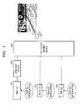
- FIG. 4 is a flowchart of a method of modulating a particular light source used for laser display according to an embodiment of the present invention.
- operation 401 light output from a semiconductor laser is digitally modulated to a frequency higher than a repetition frequency required to perform laser image display.
- operation 402 at least one high-speed pulse is inserted into a period of the modulated output light and the number of the inserted high-speed pulses is adjusted so as to control the brightness of a pixel.
- a green light source which is difficult to obtain using analog modulation, can be easily obtained from light output from a green semiconductor laser using digital modulation that is not sensitive to a change in wavelength.
- the brightness of a pixel can be distinctively realized using digital on/off modulation. As a result, improved laser display can be provided.
Landscapes
- Physics & Mathematics (AREA)
- Optics & Photonics (AREA)
- Engineering & Computer Science (AREA)
- Multimedia (AREA)
- Signal Processing (AREA)
- General Physics & Mathematics (AREA)
- Semiconductor Lasers (AREA)
- Projection Apparatus (AREA)
- Optical Modulation, Optical Deflection, Nonlinear Optics, Optical Demodulation, Optical Logic Elements (AREA)
- Control Of Indicators Other Than Cathode Ray Tubes (AREA)
Abstract
Description
- The present invention relates to a method and apparatus for modulating a particular light source used for laser display, and more particularly, to an apparatus and method for converting tunable laser light into a green light source using quasi-phase-matching second-harmonic generation (QPM-SHG) and modulating the laser light into a stable laser display light source using digital modulation.
- This work was supported by the IT R&D program of MIC/IITA [2005-S-051, Photonic device integrated module for optical access network]
- Laser display is expressed by using a method of modulating the outputs of a blue laser, a green laser, and a red laser according to the scan period of a scan mirror. Recently, microminiature and low-power laser displays, which can be easily carried, have become popular. In order to implement these laser displays, tri-color light sources, which are modulated to a level of 20 MHz when video graphics array (VGA) images are displayed, are required. Conventionally, semiconductor lasers have implemented modulation light sources for blue and red. However, it is difficult to directly realize green color using a semiconductor laser.
- Processing light output from a wavelength-adjustable semiconductor laser, i.e., a Distributed Bragg Reflector Laser Diode (DBR LD) by using a Quasi-Phase-Matching Second-Harmonic Generation (QPM-SHG) device has been considered in order to implement green color. However, color conversion using the QPM-SHG device is so sensitive to wavelength change that when an output of the DBR-LD is modulated to about 20 MHz, it is difficult to exactly maintain the wavelength of the output. Moreover, it is difficult to adjust green light output to a desired brightness on a screen in analog mode.
- The present invention provides a method and apparatus for providing digital on/off modulation, by which output light of a semiconductor laser is modulated to a frequency that is much higher than an actually required repetition frequency of 20 MHz and a high-speed pulse is inserted into the modulated output light.
- According to an aspect of the present invention, there is provided an apparatus for modulating a particular light source for laser display. The apparatus includes a digital modulator digitally modulating light output from a semiconductor laser to a frequency higher than a repetition frequency required for laser image display, and a pixel brightness adjustor inserting at least one high-speed pulse into a period of the modulated output light, which is required for a single pixel, and adjusting a brightness of the pixel by adjusting the number of the inserted high-speed pulses.
- According to another aspect of the present invention, there is provided a method of modulating a particular light source for laser display. The method includes digitally modulating light output from a semiconductor laser to a frequency higher than a repetition frequency required for laser image display, and inserting at least one high-speed pulse into a period of the modulated output light, which is required for a single pixel, and adjusting brightness of the pixel by adjusting the number of the inserted high-speed pulses.
- The above and other features and advantages of the present invention will become more apparent by describing in detail exemplary embodiments thereof with reference to the attached drawings in which:
- FIG. 1 illustrates an apparatus for modulating a particular light source used for laser display according to an embodiment of the present invention;
- FIG. 2 illustrates high-speed pulses inserted to a period of modulated laser light according to an embodiment of the present invention;
- FIG. 3 illustrates laser projection display according to an embodiment of the present invention; and
- FIG. 4 is a flowchart of a method of modulating a particular light source used for laser display according to an embodiment of the present invention.
- Hereinafter, preferred embodiments of the present invention will be described in detail with reference to the attached drawings. In the drawings, like reference numerals refer to the like elements.
- FIG. 1 illustrates an apparatus for modulating a particular light source used for laser display according to an embodiment of the present invention. A
digital modulator 100 included in the apparatus digitally modulates light output from a semiconductor laser, e.g., a Distributed Bragg Reflector Laser Diode (DBR-LD), to a frequency higher than a repetition frequency that is normally requested to realize laser image display. - When a light source having a frequency of 20 MHz is required, the same effect can be achieved by modulating the DBR-LD to a frequency, e.g., 1 GHz, which is much higher than 20 MHz, and inserting 50 pulses having a cycle of 1 ns into a period of 50 ns of the frequency of 20 MHz. In other words, the light output from the DBR-LD can be provided at the same brightness as other analog light sources by setting the number of high-speed pulses to a natural number obtained by dividing the frequency of the modulated output light by the repetition frequency of an analog light source used to realize laser image display.
- In particular, when tunable light is converted into green light using a Quasi-Phase-Matching Second-Harmonic Generation (QPM-SHG)
device 101 and then processed by digital on/off modulation, a green light source for laser display can be obtained. - A
pixel brightness adjustor 102 inserts at least one high-speed pulse into a period required for the realization of a single pixel in the modulated light output from thedigital modulator 100, thereby generating a light source which can be used as a display light source together with other analogously modulated light sources having a low frequency, according to the number of inserted high-speed pulses. At this time, the number of high-speed pulses inserted into the period of the modulated output light corresponds closely to the brightness of the pixel. For example, when 50 high-speed pulses are inserted into a single period, brightness realized on a screen is adjusted by the number of on/off pulses among the 50 pulses. People perceive a brightness difference on the screen between when one of the 50 pulses is turned on and when all 50 pulses are turned on, at a ratio of 1:50. - The above-described method is possible due to the following reasons. Unlike analog modulation in which it is difficult to maintain the wavelength of the DBR-LD, the wavelength of the DBR-LD can be easily maintained during 1 GHz high-speed digital modulation. In addition, precise output adjustment is not needed as much in digital modulation as it is in analog modulation.
- FIG. 2 illustrates high-speed pulses inserted to a period of modulated laser light according to an embodiment of the present invention. In detail, FIG. 2 illustrates digital modulation signals including one, five, and ten pulses, respectively in a period of 50 ns in order to realize a 20 MHz pixel frequency. In other words, digital configurations, in which one, five, and ten pulses are respectively turned on, are shown. When the current of the DBR-LD is modulated in this manner, human eyes perceive the brightness at a ratio of 1:5:10 Accordingly, the same effect as the output of the DBR-LD being analogously modulated at a ratio of 1:5:10 can be obtained.
- FIG. 3 illustrates laser projection display according to an embodiment of the present invention. Referring to FIG. 3, a
blue LD 310 and ared LD 320 can directly adjust their outputs to 20 MHz so as to be suitable for pixel brightness using analog modulation without any problem. For green color, which is difficult to realize with the analog modulation, high-speed digital modulation controlling the number of pulses is used to adjust an output of a DBR-LD 301. In other words, the output light of the tunable DBR-LD 301 for green light generation is converted and digitally modulated to green light using a quasi-phase-matching second-harmonic generation (QPM-SHG)device 302. Green, blue, and red light sources are processed by atri-color mixing device 330 and projected to a screen, whereby an image is displayed. - FIG. 4 is a flowchart of a method of modulating a particular light source used for laser display according to an embodiment of the present invention. In
operation 401, light output from a semiconductor laser is digitally modulated to a frequency higher than a repetition frequency required to perform laser image display. Inoperation 402, at least one high-speed pulse is inserted into a period of the modulated output light and the number of the inserted high-speed pulses is adjusted so as to control the brightness of a pixel. - According to the present invention, a green light source, which is difficult to obtain using analog modulation, can be easily obtained from light output from a green semiconductor laser using digital modulation that is not sensitive to a change in wavelength. In addition, the brightness of a pixel can be distinctively realized using digital on/off modulation. As a result, improved laser display can be provided.
- While the present invention has been particularly shown and described with reference to exemplary embodiments thereof, it will be understood by those of ordinary skill in the art that various changes in form and details may be made therein without departing from the spirit and scope of the present invention as defined by the following claims.
Claims (6)
- An apparatus for modulating a particular light source for laser display, the apparatus comprising:a digital modulator digitally modulating light output from a semiconductor laser to a frequency higher than a repetition frequency required for laser image display; anda pixel brightness adjustor inserting at least one high-speed pulse into a period of the modulated output light, which is required for a single pixel, and adjusting a brightness of the pixel by adjusting the number of the inserted high-speed pulses.
- The apparatus of claim 1, wherein the digital modulator converts a color of tunable light output from the semiconductor laser to green light using a Quasi-Phase-Matching Second-Harmonic Generation (QPM-SHG) device and simultaneously performs digital on/off modulation.
- The apparatus of claim 1 or 2, wherein the pixel brightness adjustor sets the number of high-speed pulses to a natural number obtained by dividing a frequency of the modulated output light by the repetition frequency of an analog light source used to realize the laser image display
- A method of modulating a particular light source for laser display, the method comprising:(a) digitally modulating light output from a semiconductor laser to a frequency higher than a repetition frequency required for laser image display; and(b) inserting at least one high-speed pulse into a period of the modulated output light, which is required for a single pixel, and adjusting brightness of the pixel by adjusting the number of the inserted high-speed pulses.
- The method of claim 4, wherein operation (a) comprises converting a color of tunable light output from the semiconductor laser to green light using a Quasi-Phase-Matching Second-Harmonic Generation (QPM-SHG) device and simultaneously performing digital on/off modulation.
- The method of claim 4 or 5, wherein operation (b) comprises setting the number of high-speed pulses to a natural number obtained by dividing a frequency of the modulated output light by the repetition frequency of an analog light source used to realize the laser image display
Applications Claiming Priority (1)
| Application Number | Priority Date | Filing Date | Title |
|---|---|---|---|
| KR1020060109691A KR100819043B1 (en) | 2006-11-07 | 2006-11-07 | Modulator for a specific light source used as a laser display light source and its modulation method |
Publications (2)
| Publication Number | Publication Date |
|---|---|
| EP1921868A2 true EP1921868A2 (en) | 2008-05-14 |
| EP1921868A3 EP1921868A3 (en) | 2008-11-19 |
Family
ID=39030868
Family Applications (1)
| Application Number | Title | Priority Date | Filing Date |
|---|---|---|---|
| EP07120146A Ceased EP1921868A3 (en) | 2006-11-07 | 2007-11-07 | Method and apparatus for modulating particular light source used for laser display |
Country Status (4)
| Country | Link |
|---|---|
| US (1) | US7810952B2 (en) |
| EP (1) | EP1921868A3 (en) |
| JP (1) | JP4856613B2 (en) |
| KR (1) | KR100819043B1 (en) |
Families Citing this family (2)
| Publication number | Priority date | Publication date | Assignee | Title |
|---|---|---|---|---|
| JP5609370B2 (en) * | 2010-07-23 | 2014-10-22 | 船井電機株式会社 | Image display device |
| CN111505841B (en) * | 2019-01-31 | 2023-06-23 | 成都理想境界科技有限公司 | Laser modulation method, laser scanning device and system |
Citations (1)
| Publication number | Priority date | Publication date | Assignee | Title |
|---|---|---|---|---|
| JP2001189520A (en) * | 1999-12-28 | 2001-07-10 | Sony Corp | Light source device and projection display device using the same |
Family Cites Families (10)
| Publication number | Priority date | Publication date | Assignee | Title |
|---|---|---|---|---|
| JPS56153333A (en) | 1980-04-30 | 1981-11-27 | Fuji Photo Film Co Ltd | Laser recorder |
| JPH09115825A (en) | 1995-10-19 | 1997-05-02 | Nikon Corp | Scanning projection exposure equipment |
| US5835650A (en) | 1995-11-16 | 1998-11-10 | Matsushita Electric Industrial Co., Ltd. | Optical apparatus and method for producing the same |
| JP2002043698A (en) * | 1999-12-22 | 2002-02-08 | Yokogawa Electric Corp | SHG laser light source and method of modulating SHG laser light source |
| US6671297B2 (en) | 2001-04-26 | 2003-12-30 | Matsushita Electric Industrial Co., Ltd. | Wavelength conversion device |
| JP4174195B2 (en) * | 2001-05-28 | 2008-10-29 | キヤノン株式会社 | Image display device |
| JP2003295243A (en) * | 2002-04-04 | 2003-10-15 | Canon Inc | Harmonic light source device, driving method thereof, image display device using the same, image forming device, optical recording device |
| JP3793208B2 (en) * | 2004-03-23 | 2006-07-05 | キヤノン株式会社 | Modulated light source, image display apparatus having the same, and driving method of modulated light source |
| US7269193B2 (en) | 2004-06-28 | 2007-09-11 | Fuji Film Corp. | Semiconductor laser driving circuit and image recording apparatus |
| KR100621216B1 (en) * | 2004-12-10 | 2006-09-13 | 한국전자통신연구원 | Optical transmitter with analog / digital mixing method |
-
2006
- 2006-11-07 KR KR1020060109691A patent/KR100819043B1/en not_active Expired - Fee Related
-
2007
- 2007-10-31 US US11/930,727 patent/US7810952B2/en not_active Expired - Fee Related
- 2007-11-07 EP EP07120146A patent/EP1921868A3/en not_active Ceased
- 2007-11-07 JP JP2007289979A patent/JP4856613B2/en not_active Expired - Fee Related
Patent Citations (1)
| Publication number | Priority date | Publication date | Assignee | Title |
|---|---|---|---|---|
| JP2001189520A (en) * | 1999-12-28 | 2001-07-10 | Sony Corp | Light source device and projection display device using the same |
Also Published As
| Publication number | Publication date |
|---|---|
| US7810952B2 (en) | 2010-10-12 |
| US20080117492A1 (en) | 2008-05-22 |
| JP4856613B2 (en) | 2012-01-18 |
| KR100819043B1 (en) | 2008-04-02 |
| EP1921868A3 (en) | 2008-11-19 |
| JP2008116968A (en) | 2008-05-22 |
Similar Documents
| Publication | Publication Date | Title |
|---|---|---|
| EP2271120B1 (en) | Light source device, video projector and video projection method | |
| EP2169964B1 (en) | Projection apparatus and projection method | |
| US9462244B2 (en) | Image display apparatus and optical component | |
| US9542911B2 (en) | Display apparatus and method for controlling display apparatus | |
| KR20120117717A (en) | Light source device, projection apparatus, and projection method | |
| US20050280850A1 (en) | Color signal processing apparatus and method | |
| EP2290443A1 (en) | Light source device, projection apparatus, and projection method | |
| JP4546499B2 (en) | Image display device | |
| JP2014021235A (en) | Projector and light emission control method in the same | |
| US20070035723A1 (en) | Image display device and light source device | |
| JP2005276902A (en) | Modulated light source, image display apparatus having the same, and driving method of modulated light source | |
| US7810952B2 (en) | Method and apparatus for modulating particular light source used for laser display | |
| JP2014063092A (en) | Display device, projector, and control method for display device | |
| JP5407254B2 (en) | Projection apparatus, projection method, and program | |
| JP2011203292A (en) | Projection display device | |
| JP2014066805A (en) | Projector and light emission control method in projector | |
| JP5445575B2 (en) | Projection apparatus and projection method | |
| JP5245944B2 (en) | Projection apparatus, projection method, and program | |
| JP2009080277A (en) | Projection image display device | |
| JP2017010057A (en) | Projector and projector light emission control method | |
| US20110050662A1 (en) | Display | |
| JP2008026355A (en) | Light source control device | |
| KR100396677B1 (en) | Apparatus for laser diode optic module of laser system |
Legal Events
| Date | Code | Title | Description |
|---|---|---|---|
| PUAI | Public reference made under article 153(3) epc to a published international application that has entered the european phase |
Free format text: ORIGINAL CODE: 0009012 |
|
| AK | Designated contracting states |
Kind code of ref document: A2 Designated state(s): AT BE BG CH CY CZ DE DK EE ES FI FR GB GR HU IE IS IT LI LT LU LV MC MT NL PL PT RO SE SI SK TR |
|
| AX | Request for extension of the european patent |
Extension state: AL BA HR MK RS |
|
| PUAL | Search report despatched |
Free format text: ORIGINAL CODE: 0009013 |
|
| AK | Designated contracting states |
Kind code of ref document: A3 Designated state(s): AT BE BG CH CY CZ DE DK EE ES FI FR GB GR HU IE IS IT LI LT LU LV MC MT NL PL PT RO SE SI SK TR |
|
| AX | Request for extension of the european patent |
Extension state: AL BA HR MK RS |
|
| 17P | Request for examination filed |
Effective date: 20090519 |
|
| 17Q | First examination report despatched |
Effective date: 20090618 |
|
| AKX | Designation fees paid |
Designated state(s): AT BE BG CH CY CZ DE DK EE ES FI FR GB GR HU IE IS IT LI LT LU LV MC MT NL PL PT RO SE SI SK TR |
|
| STAA | Information on the status of an ep patent application or granted ep patent |
Free format text: STATUS: THE APPLICATION HAS BEEN REFUSED |
|
| 18R | Application refused |
Effective date: 20110111 |