EP1921386A2 - Hotplate control and method for manual adjustment on an operating strip - Google Patents
Hotplate control and method for manual adjustment on an operating strip Download PDFInfo
- Publication number
- EP1921386A2 EP1921386A2 EP07119886A EP07119886A EP1921386A2 EP 1921386 A2 EP1921386 A2 EP 1921386A2 EP 07119886 A EP07119886 A EP 07119886A EP 07119886 A EP07119886 A EP 07119886A EP 1921386 A2 EP1921386 A2 EP 1921386A2
- Authority
- EP
- European Patent Office
- Prior art keywords
- control
- finger
- operating line
- receiving elements
- line
- Prior art date
- Legal status (The legal status is an assumption and is not a legal conclusion. Google has not performed a legal analysis and makes no representation as to the accuracy of the status listed.)
- Withdrawn
Links
Images


Classifications
-
- F—MECHANICAL ENGINEERING; LIGHTING; HEATING; WEAPONS; BLASTING
- F24—HEATING; RANGES; VENTILATING
- F24C—DOMESTIC STOVES OR RANGES ; DETAILS OF DOMESTIC STOVES OR RANGES, OF GENERAL APPLICATION
- F24C7/00—Stoves or ranges heated by electric energy
- F24C7/08—Arrangement or mounting of control or safety devices
- F24C7/082—Arrangement or mounting of control or safety devices on ranges, e.g. control panels, illumination
- F24C7/083—Arrangement or mounting of control or safety devices on ranges, e.g. control panels, illumination on tops, hot plates
Definitions
- the invention relates to a controller for a household appliance, in particular a hob control with a plurality of reflection-sensitive infrared sensors and to a method for manual adjustment on a control line.
- the basic function of the present arrangement and method is therefore to accurately measure the position of the finger of an operator on the operating line and, for example to convert into a corresponding cooking level.
- this adjustment is generally well ensured, as long as the function is controlled substantially only by the scattered light of the transmitting diodes.
- the setting is additionally influenced by external light from the environment.
- halogen light which has a high proportion of IR radiation.
- the IR-receiving elements are equipped with daylight filters, the IR radiation above a certain brightness is sufficient to saturate a receiving element into saturation.
- daylight or ambient light contain to a certain extent IR radiation.
- the hob control according to the invention is equipped with a plurality of infrared sensors, which are sensitive to reflection in the usual way to generate a signal when touched by a finger (touch control).
- a plurality of IR receiving elements along a control line is arranged, and indeed according to the invention with such a density that an attached to the operating line finger of the operator covers at least one of the IR receiving elements inevitably.
- the ambient light is shadowed for at least one receiving element and thus achieves a uniform signal evaluation along the entire operating line even under unfavorable circumstances.
- Particularly preferred is a receiver spacing of about 100 mm.
- the number of IR transmitting diodes can be saved in comparison with the prior art. It is sufficient to arrange a significantly smaller number of IR transmitting diodes in a correspondingly lower density next to the operating line.
- the number of IR transmitting diodes can be half as large as the number of IR receiving elements, in which case expediently each of the IR transmitting diodes is arranged in the immediate vicinity of each second receiving element next to the operating line with a density of 20 mm per transmitter.
- a receiving element with a pair of sensors always changes along the operating line, as a result of which the IR light emitted by a transmitting diode is reflected onto an average of three receiving elements.
- the method aspect of the invention is characterized according to claim 14, characterized in that both the radiation of the optical transmitter reflected by the finger and the radiation of the ambient light shaded by the finger are used to evaluate the finger position.
- the combined incidence of light, in which the IR component in particular is of importance, is quantified at all optical receivers. Since the operating point of the optical receiver (phototransistors) is tuned to that operating state in which the light coming from and reflected from the optical transmitters is shaded by the ambient light is measured under almost all environmental conditions produces an evaluable signal distribution.
- the evaluation of the signal distribution happens in principle as in the DE 10 2004 054 322 B3 disclosed.
- the position of the finger can be calculated by averaging (focus of light distribution) or by similar evaluation methods as in DE.
- the advantage of the new arrangement is that always at least one receiving element, which is in particular an IR phototransistor, is darkened. Due to the darkening, the working range of at least this transistor is located in a region provided for signal evaluation by reflection. The signal swing of this receiver element can therefore be evaluated in each case.
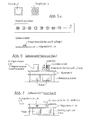
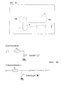
- Fig. 1 the cited prior art starts from an operating line, on which transmitter and receiver are arranged alternately.
- the incidence of light therefore leads from a plurality of transmitters 1... N2 via the reflections to a plurality of receivers 1... N1.
- Each transmitter essentially serves two adjacent receivers and, analogously, each receiver receives light from substantially two adjacent transmitters.
- the receiving elements 4 denser and the transmitter 6 less dense.
- a pair of sensors 2 consististing of a phototransistor 4 and a transmitting diode 6) are each arranged between two individual receivers (phototransistors 4). The light of a transmitter 6 can under favorable circumstances be evaluated at the three adjacent receivers 4 (see FIG.
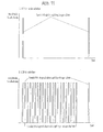
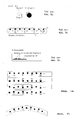
- Fig. 2 and Fig. 3 two typical signal distributions are shown in the prior art.
- the proximity of a transmitter and a receiver with the associated light reflection is referred to as sensor S (i).
- This signal distribution can be determined in time-sequential control of the transmitter 6 and respective detection of the adjacent receiver 4.
- the finger actuates the control further to the left than in Fig. 3.
- Even a small change in the position of the finger 18 leads to a noticeable change in the signal distribution of the sensors S1 to S8.
- this Effect also makes use of the present invention, as Figs. 2b and 3b show.
- FIGS. 2a and 3a how the arrangement according to the prior art reacts to a high ambient brightness (case a).
- the finger 18 happens to be located just above one of the receivers 4.
- the ambient light in this case is shaded (ie, the remaining receivers are driven to saturation by the ambient light) and the two "proximity sensors" S2 and S3 at which the shadowed receiving element 4 is involved, receive the reflected IR light in the normal working range.
- the finger 18 randomly occupies an area between two sensors, and due to the continuous saturation, there is no evaluable signal distribution.
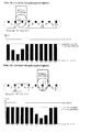
- FIGS. 2b and 3b show the signal distribution according to the invention at normal ambient brightness (case b), FIGS. 2c and 3c at high ambient brightness (case c).
- case b the higher receiver density of the invention already provides for a better evaluable envelope with more points; in case c, an evaluation is still possible at very high ambient brightness.
- Fig. 4 shows a general formula for calculating the center of gravity of the measured light distribution.
- This center of gravity X represents the actual position of the fingertip with great accuracy.
- the result X is a value between 1 and N1 (assuming N1 receiver) and can be transformed to a different value range by suitable normalization.
- the resolution is also dependent on the quantization of the sensor signals.
- S (i) [0, 0, 2, 5, 6, 1, 0, 0].
- an extreme value can also be determined, by interpolation with a parabolic, z. B. quadratic function. This is - similar to the utility model DE 20 2004 019 489 U1 8-10, the maximum value of the parabola sought is approximated by the three most out of the frame measurements.
- FIG. 5b shows the structure optimized in comparison with the cited prior art according to FIG. 5a.
- the transmitter and receiver are no longer mounted alternately on the operating line 18 (FIG. 5), but the plurality N1 of IR receiving elements 4 are arranged along the operating line 16 in greater density than the number N2 of IR transmitting diodes 6.
- the IR receiving elements 4 are so dense that a finger 18 placed on the operating line 16 necessarily covers at least one of the IR receiving elements 4.
- half the number N2 of IR transmitter diodes 6 is disposed in the immediate vicinity of each second IR receiving element 4 adjacent to the operating line 16.
- the side section through the supporting circuit board 20 according to Fig. 5b shows that the optical components according to an embodiment of the invention can be arranged on the upper side of the carrier material.
- the height compared to a prior art, which is shown in Fig. 6, is substantially lower, because the previously used light guide is omitted.
- the further embodiment of the invention according to Fig. 7 shows a very low height, because the optical components (transmitter 6 and receiver 4) can even be laid on the underside of the supporting circuit board 20.
- recesses 22 are provided in the substrate 20 in this case.
- Fig. 10 shows two possibilities for such recesses 22.
- a number of optical components 4, 6 is arranged below a slot 24 which extends over the entire operating line 16.
- a smaller slot 24 is alternatively provided per optical component 4, 6. It can also satisfy a number of holes 24.
- FIGS. 8 and 9 an alternative is still shown which relates to the display elements 26.
- the display elements 26 serve to visibly display the set parameter of the hob control for the operator.
- Fig. 8 and 9 is an analog representation in the form a bargraph.
- the illustration in FIGS. 8 and 9 follows on from the embodiment according to FIG. 5a, which is readily transferable to the embodiment according to the invention according to FIG. 5b.
- the optical components 4, 6 are arranged with a small overall height on the upper side of the carrier material 20.
- the additional arrangement of the display elements 26 also applies to underlying components 4, 6, 26 as shown in Fig. 7.
- the operating line according to Fig. 5 and Fig. 5b is supplemented by the fact that display elements 26 are arranged at the intermediate positions between each two infrared sensors S1, S2, S3.
- the display elements do not interfere with the sensors 2 due to their shorter visible light wavelength, while the infrared sensors 2 do not cause a visible display due to their longer wavelength.
- Fig. 9 which in its structure with Fig. 5a bez.
- Fig. 5b instead of the infrared sensors 2 also sensors for light in the visible range are used.
- the display 26 is executed as a "bar graph" and controlled with appropriate pulse packets. At a higher density of the pulse packet, the light of the light emitting diode 6 is visible, while it remains invisible at a lower pulse packet density (controllable by pulse width modulation PWM).
- the sensor evaluation is achieved by time-division multiplexing and synchronization with the receivers 4, i. H. the light-emitting diodes 6 are activated one after the other in the direction of the operating line 16 and the receivers 4 are activated in these time windows.
- the series of light-emitting diodes 6 as a step indicator or bar graph is superimposed on the time multiplex just explained, ie a display-active light-emitting diode 6 is activated almost permanently. Since the receivers 4 are turned off at this time, the operation control operation is not affected.
- the light emitting diodes 6 which emit visible light are classified into two groups depending on the position X of the actuator or finger 18.
- the pulse train is used, which is shown in Fig. 11 above. These short light pulses are not visible to the human eye, but allow the receiver 4 to detect the reflected light intensity.
- This control undergoes the group of light-emitting diodes 6, which is located to the right of the finger 18 on the operating line 16.
- the other group of LEDs 6, which is located on the left of the fingertip 18 on the operating line 16 undergoes the drive shown in Fig. 11 below.
- This pulse packet makes the transmitter visible to the human eye and displays the associated heating power as a bar graph.
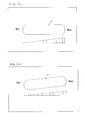
- Fig. 12a and Fig. 12b show two examples of an actuating surface 14 which is graphically displayed on the hob and below which the associated operating line 16 is located.
- the actuating surface 14 is rectilinear, i. a finger 18 may touch or linearly sweep the actuating surface 14 between the MIN and MAX values.
- On a the actuating surface 14 associated graphical symbol (wedge symbol) can be displayed in the manner of a slide control cooking level.
- the display elements can also be arranged below the actuating surface 14.
- actuating surface 14 is horizontal, obliquely aligned in Fig. 12b.
- the operating line 16 may also be curved or curved.
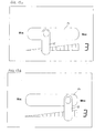
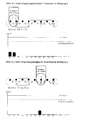
- the hob control according to the invention is operated as follows. It is possible, by touching a certain position on the actuating surface 14 directly select a cooking level, which is assigned to this position. For example, is the maximum cooking level that can be set "9" and it is the actuating surface 14 touched in the first third, so the cooking level "3" is set. This process of direct selection of the cooking level "3" is shown in Fig. 13a, wherein the cooking level 3 is displayed in this case as a digital digit for display.
- the OFF position must be precisely marked for operational safety reasons. This marking can be made in the actuating surface 14 e.g. be done by the left edge of the operation field 14 is highlighted by an OFF symbol.
- the timing of a setting operation is typically as follows: By placing the finger 18 on the operating field 14 of the cooking position sensor for a predetermined time (eg 0.5 seconds), the hotplate can be activated. If one now moves the finger 18 over the sensitive area 14, then the value X changes depending on the operation. Is now the intended X set, it must be confirmed by persisting in the appropriate position for a certain time (eg 0.3 seconds). Alternatively, of course, the value displayed after the activation of the hotplate X can be taken over by a persistence of the finger 18 (direct selection).
- a predetermined time eg 0.5 seconds
- This adjustment mode has the advantage that the complete cooking zone is seen as a sensor. For the operating line, one obtains almost the same characteristics as a single sensor, e.g. the actuation distance and the safety against an independent turning on external light concerns. In addition, by briefly holding on to the selected position (confirmation of the setting value), an oblique pulling away of the finger no longer affects the set value.
- Fig. 14 shows four straight-line embodiments of the operating line according to the invention.
- the IR transmitting diodes with the lower density are arranged in the immediate vicinity of each second IR receiving element next to the operating line. It is preferred to line up the number N2 of IR transmitting diodes only on one side of the IR receiving elements constituting the operating line 16.
- the IR-receiving elements can also form a zigzagged polygon on the overall straight line of operation.
- Each operating line can end at the edges either with a receiving element 4 and / or with a sensor pair 2 (consisting of a receiving element 4 and a transmitting diode 6).
- the operating line can be bent as shown in Fig. 15, wherein the IR-receiving elements 4 can form a zigzag-shaped polygonal line on the arcuate operating line.
- Fig. 16 shows electrical schematic diagrams of the transmitter 6 according to the invention and receiver 4.
- the transmitting diodes 6 are driven by light pulses, as shown in Fig. 11 above. These control pulses are not visible to the operator, either because the hob control has been designed as an infrared control and has been equipped with IR transmitter diodes or either because the control pulses shown in Fig. 11 above are too short to be perceptible to the human eye.
- the receivers 4 are preferably designed as IR phototransistors. According to the wiring in Fig. 16, an increased light intensity leads to a voltage drop of the emitter signal to saturation. Subsequently, the measurement signal can be normalized to be proportional to the intensity of the light signal to which the photoreceiver (including daylight filter) is sensitive. Such normalized light measuring signals are shown by way of example in the distributions according to FIGS. 2 and 3.
Abstract
Description
Die Erfindung bezieht sich auf eine Steuerung für ein Haushaltsgerät, insbesondere eine Kochfeldsteuerung mit einer Vielzahl von reflexionsempfindlichen Infrarotsensoren sowie auf ein Verfahren zum manuellen Einstellen an einer Bedienlinie.The invention relates to a controller for a household appliance, in particular a hob control with a plurality of reflection-sensitive infrared sensors and to a method for manual adjustment on a control line.
Aus dem Patent
Aus dem Patent
Die grundsätzliche Funktion der vorliegenden Anordnung und des vorliegenden Verfahrens besteht demnach darin, die Position des Fingers einer Bedienperson auf der Bedienlinie genau zu messen und beispielsweise in eine entsprechende Kochstufe umzusetzen. Versuche der Anmelderin haben ergeben, dass diese Einstellung im allgemeinen gut gewährleistet ist, und zwar so lange, wie die Funktion im wesentlichen nur von dem streuend reflektierten Licht der Sendedioden gesteuert wird. In der Praxis wird die Einstellung jedoch zusätzlich von Fremdlicht aus der Umgebung beeinflusst.The basic function of the present arrangement and method is therefore to accurately measure the position of the finger of an operator on the operating line and, for example to convert into a corresponding cooking level. Experiments by the Applicant have shown that this adjustment is generally well ensured, as long as the function is controlled substantially only by the scattered light of the transmitting diodes. In practice, however, the setting is additionally influenced by external light from the environment.
Besonders problematisch ist in diesem Zusammenhang, so hat sich im Laufe der Untersuchung der erfindungsgemässen Zusammenhänge ergeben, Halogen-Licht, das einen hohen Anteil an IR-Strahlung hat. Obwohl die IR-Empfangselemente mit Tageslicht-Filtern ausgestattet sind, ist die IR-Strahlung ab einer bestimmten Helligkeit ausreichend, um ein Empfangselement in die Sättigung zu steuern. Aber auch Tageslicht bzw. Umgebungslicht enthalten zu einem gewissen Anteil IR-Strahlung.Particularly problematic in this context, as revealed in the course of the investigation of the inventive context, halogen light, which has a high proportion of IR radiation. Although the IR-receiving elements are equipped with daylight filters, the IR radiation above a certain brightness is sufficient to saturate a receiving element into saturation. But daylight or ambient light contain to a certain extent IR radiation.
Diese Sättigung kann dazu führen, dass die Bedienlinie nicht mehr an allen Stellen gleichmäßig bedienbar ist. Die Versuche haben ergeben, dass die Fingerberührung ab einer Umgebungshelligkeit von ca. 700 lux nur noch in unmittelbarer Nähe bzw. direkt oberhalb eines Empfangselements funktioniert. Liegt der Finger hingegen zwischen zwei Empfangselementen, so verhält sich die Steuerung so, als ob kein Finger auf der Bedienlinie aufläge. Dieses Problem tritt bei einzelnen IR-Sensoren nicht auf, nur bei Bedienlinien.This saturation can mean that the operating line can no longer be operated uniformly in all places. The experiments have shown that the finger touch works from an ambient brightness of about 700 lux only in the immediate vicinity or directly above a receiving element. If, on the other hand, the finger lies between two receiving elements, then the controller behaves as if there were no finger on the operating line. This problem does not occur with individual IR sensors, only with operating lines.
Die Aufgabe der Erfindung besteht darin, dieses Problem zu lösen, d. h.
- - die IR-Empfangselemente und die IR-Sendedioden konstruktiv zweckmäßig entlang der Bedienlinie anzuordnen, und zwar so, dass
- - die Positionsauflösung der reflektierenden Fingerkuppe auch unter ungünstigen Umgebungsbedingungen gewährleistet ist.
- - Conveniently arrange the IR-receiving elements and the IR transmitting diodes along the operating line, in such a way that
- - The position resolution of the reflective fingertip is guaranteed even under unfavorable environmental conditions.
Gelöst wird diese Aufgabe in ihrem Anordnungsaspekt mittels einer Kochfeldsteuerung nach dem unabhängigen Anspruch 1, in ihrem Verfahrensaspekt mittels eines Einstellverfahrens nach dem unabhängigen Anspruch 14. Zweckmäßige Weiterbildungen gehen aus den jeweiligen Unteransprüchen hervor.This problem is solved in its arrangement aspect by means of a hob control according to
Die erfindungsgemäße Kochfeldsteuerung ist mit einer Vielzahl von InfrarotSensoren ausgestattet, die in üblicher Weise reflexionsempfindlich sind, um bei Berührung durch einen Finger ein Signal zu erzeugen (Touch Control). Dabei ist eine Mehrzahl von IR-Empfangselementen längs einer Bedienlinie angeordnet, und zwar erfindungsgemäß mit einer derartigen Dichte, dass ein auf die Bedienlinie aufgesetzter Finger der Bedienperson mindestens eines der IR-Empfangselemente zwangsläufig abdeckt. Dadurch wird das Umgebungslicht für mindestens ein Empfangselement abgeschattet und so eine gleichmäßige Signalauswertung längs der gesamten Bedienlinie auch unter ungünstigen Umständen erzielt. Besonders bevorzugt wird ein Empfängerabstand von etwa 100 mm.The hob control according to the invention is equipped with a plurality of infrared sensors, which are sensitive to reflection in the usual way to generate a signal when touched by a finger (touch control). In this case, a plurality of IR receiving elements along a control line is arranged, and indeed according to the invention with such a density that an attached to the operating line finger of the operator covers at least one of the IR receiving elements inevitably. As a result, the ambient light is shadowed for at least one receiving element and thus achieves a uniform signal evaluation along the entire operating line even under unfavorable circumstances. Particularly preferred is a receiver spacing of about 100 mm.
Anlässlich der Erhöhung der Empfängerdichte hat sich aber auch gezeigt, dass umgekehrt bei der Anzahl der IR-Sendedioden im Vergleich zum Stand der Technik gespart werden kann. Es genügt, eine deutlich geringere Anzahl von IR-Sendedioden in entsprechend geringerer Dichte neben der Bedienlinie anzuordnen. Insbesondere kann die Anzahl der IR-Sendedioden halb so groß sein wie die Anzahl der IR-Empfangselemente, wobei dann zweckmäßigerweise jede der IR-Sendedioden in unmittelbarer Nachbarschaft jedes zweiten Empfangselements neben der Bedienlinie mit einer Dichte von 20 mm pro Sender angeordnet ist. Im Ergebnis wechselt längs der Bedienlinie immer ein Empfangselement mit einem Sensorpärchen ab, wodurch das von einer Sendediode abgestrahlte IR-Licht auf durchschnittlich drei Empfangselemente reflektiert wird.On the occasion of the increase in the receiver density, however, it has also been shown that conversely the number of IR transmitting diodes can be saved in comparison with the prior art. It is sufficient to arrange a significantly smaller number of IR transmitting diodes in a correspondingly lower density next to the operating line. In particular, the number of IR transmitting diodes can be half as large as the number of IR receiving elements, in which case expediently each of the IR transmitting diodes is arranged in the immediate vicinity of each second receiving element next to the operating line with a density of 20 mm per transmitter. As a result, a receiving element with a pair of sensors always changes along the operating line, as a result of which the IR light emitted by a transmitting diode is reflected onto an average of three receiving elements.
Der Verfahrensaspekt der Erfindung ist gemäß dem Anspruch 14 dadurch gekennzeichnet, dass sowohl die vom Finger reflektierte Strahlung der optischen Sender als auch die vom Finger abgeschattete Strahlung des Umgebungslichts zur Auswertung der Fingerposition herangezogen werden. Der kombinierte Lichteinfall, bei dem insbesondere der IR-Anteil von Bedeutung ist, wird an allen optischen Empfänger quantitativ erfasst. Da der Arbeitspunkt der optischen Empfänger (Fototransistoren) auf denjenigen Betriebszustand abgestimmt ist, bei dem das von den optischen Sendern kommende und reflektierte Licht unter Abschattung des Umgebungslichts gemessen wird, entsteht unter fast allen Umgebungsbedingungen eine auswertbare Signalverteilung.The method aspect of the invention is characterized according to
Die Auswertung der Signalverteilung geschieht prinzipiell wie in der
Zweckmäßige Weiterbildungen und weitere vorteilhafte Eigenschaften werden anhand von zeichnerisch dargestellten Ausführungsbeispielen erläutert. Dabei zeigt
- Abb. 1 eine schematische Darstellung des Lichteinfalls durch Reflexion, und zwar im Übergang vom Stand der Technik zur Erfindung;
- Abb. 2 für eine bestimmte Stellung des Betätigers oder Fingers eine Signalverteilung des Lichteinfalls auf eine Bedienlinie nach dem Stand der Technik;
- Abb. 2a eine Signalverteilung des Lichteinfalls wie in Abb. 2, jedoch bei hoher Umgebungshelligkeit;
- Abb. 2b eine Signalverteilung des Lichteinfalls wie in Abb. 2 bei niedriger (normaler) Umgebungshelligkeit, jedoch bei einer erfindungsgemäßen Sensoranordnung mit höherer Empfängerdichte;
- Abb. 2c eine Signalverteilung eines Lichteinfalls wie in Abb. 2b mit erfindungsgemäß höherer Empfängerdichte, und mit hoher Umgebungshelligkeit vergleichbar mit Abb. 2a;
- Abb. 3 eine Signalverteilung wie in Abb. 2 nach dem Stand der Technik, jedoch für eine andere Stellung des Betätigers oder Fingers;
- Abb. 3a eine Signalverteilung des Lichteinfalls wie in Abb. 3, jedoch bei hoher Umgebungshelligkeit;
- Abb. 3b eine Signalverteilung eines Lichteinfalls wie in Abb. 3 bei niedriger (normaler) Umgebungshelligkeit, jedoch bei einer erfindungsgemäßen Sensoranordnung mit höherer Empfängerdichte;
- Abb. 3c eine Signalverteilung des Lichteinfalls wie in Abb. 3b mit erfindungsgemäß höherer Empfängerdichte, jedoch mit einer hohen Umgebungshelligkeit vergleichbar mit Abb. 3a;
- Abb. 4 eine Formel zur Berechnung der aktuellen Fingerposition X jeweils als Schwerpunkt der erfindungsgemäßen Lichtsignalverteilungen, wie sie in Abb. 2b, 2c, 3b und 3c dargestellt sind;
- Abb. 5a eine Aufsicht auf optische Komponenten, Sender und Empfänger, sowie eine Aufsicht auf einen Träger (Leiterplatte) sowie eine Schnittansicht von der schmalen Seite des Trägers, wobei die optischen Komponenten gemäß dem zitierten Stand der Technik abwechselnd längs der Bedienlinie angeordnet sind;
- Abb. 5b Aufsichten und eine Seitenansicht wie in Abb. 5, jedoch angeordnet nach einem erfindungsgemäßen Ausführungsbeispiel;
- Abb. 6 einen Lichtleitsockel und ein Anzeigeelement nach einem Stand der Technik;
- Abb. 7 eine Ausführungsform der Erfindung, bei der die optischen Sender und Empfänger (und auch die Anzeigeelemente) auf der Unterseite des Trägers angeordnet sind;
- Abb. 8 eine auf die erfindungsgemäße Kochfeldsteuerung übertragene Ausführungsform, bei der die Anzeigeelemente (sichtbares Licht) in Zwischenpositionen zwischen den optischen Komponenten (Infrarotsender und Infrarotempfänger) angeordnet sind;
- Abb. 9 alternativ zu der Kochfeldsteuerung nach Abb. 8 eine Anordnung, bei der die optischen Komponenten (Sender und Empfänger) mit Wellenlängen im sichtbaren Bereich arbeiten und die optischen Sender gleichzeitig als Anzeigeelemente benutzt werden;
- Abb. 10 zwei Aufsichten auf eine unter dem Träger liegende Reihe von Komponenten nach Abb. 7, wobei die Aussparung im Trägermaterial alternativ als einziges großes Langloch längs der Bedienlinie oder als Reihe von kleineren Öffnungen ausgebildet sein kann;
- Abb. 11 zwei Zeitdiagramme von gesendeten, reflektierten und empfangenen Lichtimpulsen, wobei das obere Diagramm eine Steuerung eines Empfängers ohne sichtbare Anzeige und das untere Diagramm eine Steuerung eines Empfängers sowie zusätzliche Impulse für eine Sichtanzeige darstellen;
- Abb. 12a eine geradlinige, horizontale Betätigungsfläche einer erfindungsgemäßen Kochfeldsteuerung, unter der funktionell die Bedienlinie angeordnet ist;
- Abb. 12b eine geradlinige, schräge Betätigungsfläche einer erfindungsgemäßen Kochfeldsteuerung;
- Abb. 13a eine direkte Anwahl einer Kochstufe ;
- Abb. 13b und Abb. 13c eine Erniedrigung der Kochstufe durch Überstreichen der Betätigungsfläche von rechts nach links;
- Abb. 14 vier Ausführungsformen von geradlinigen oder zickzackförmigen Bedienlinien nach der Erfindung;
- Abb. 15 eine Ausführungsform einer gebogenen, zickzackförmigen Bedienlinie nach der Erfindung;
- Abb. 16 elektrische Prinzipschaltbilder der erfindungsgemäßen Sender und Empfänger.
- Figure 1 is a schematic representation of the light incidence by reflection, in the transition from the prior art to the invention.
- Fig. 2 for a given position of the actuator or finger, a signal distribution of the light incident on a line of operation according to the prior art;
- Fig. 2a shows a signal distribution of light incidence as in Fig. 2, but at high ambient brightness;
- Fig. 2b shows a signal distribution of the light incidence as in Fig. 2 at low (normal) ambient brightness, but in a sensor arrangement according to the invention with a higher receiver density.
- Fig. 2c shows a signal distribution of a light incidence as in Fig. 2b with inventively higher receiver density, and with high ambient brightness comparable to Fig. 2a;
- Fig. 3 shows a signal distribution as in Fig. 2 according to the prior art, but for a different position of the actuator or finger;
- Fig. 3a shows a signal distribution of light incidence as in Fig. 3, but at high ambient brightness;
- Fig. 3b shows a signal distribution of a light incidence as in Fig. 3 at low (normal) ambient brightness, but in a sensor arrangement according to the invention with a higher receiver density;
- Fig. 3c shows a signal distribution of the light incidence as in Fig. 3b with inventively higher receiver density, but with a high ambient brightness comparable to Fig. 3a;
- FIG. 4 shows a formula for calculating the current finger position X in each case as the center of gravity of the light signal distributions according to the invention, as illustrated in FIGS. 2b, 2c, 3b and 3c;
- Fig. 5a is a plan view of optical components, transmitter and receiver, as well as a view of a support (printed circuit board) and a sectional view from the narrow side of the carrier, wherein the optical components according to the cited prior art are arranged alternately along the operating line;
- Fig. 5b top views and a side view as in Fig. 5, but arranged according to an embodiment of the invention;
- FIG. 6 shows a light guide base and a display element according to a prior art;
- Fig. 7 shows an embodiment of the invention in which the optical transmitters and receivers (and also the display elements) are arranged on the underside of the carrier;
- FIG. 8 shows an embodiment transmitted to the hob control according to the invention, in which the display elements (visible light) are arranged in intermediate positions between the optical components (infrared transmitter and infrared receiver);
- FIG. 9 shows an arrangement in which the optical components (transmitter and receiver) operate with wavelengths in the visible range and the optical transmitters are simultaneously used as display elements, as an alternative to the hob control according to FIG. 8;
- Fig. 10 shows two plan views of a sub-carrier row of components according to Fig. 7, wherein the recess in the carrier material may alternatively be formed as the only large slot along the operating line or as a series of smaller openings;
- Fig. 11 shows two timing diagrams of transmitted, reflected and received light pulses, the upper diagram representing control of a receiver without visible indication and the lower diagram representing control of a receiver and additional pulses for visual display;
- Fig. 12a a rectilinear, horizontal actuating surface of a hob control according to the invention, under which the operating line is functionally arranged;
- Fig. 12b a rectilinear, oblique actuating surface of a hob control according to the invention;
- Fig. 13a a direct selection of a cooking level;
- Fig. 13b and Fig. 13c a lowering of the cooking level by sweeping the actuating surface from right to left;
- Fig. 14 shows four embodiments of rectilinear or zigzag operating lines according to the invention;
- Fig. 15 shows an embodiment of a curved, zigzag-shaped operating line according to the invention;
- Fig. 16 electrical schematic diagrams of the transmitter and receiver according to the invention.
Gemäß Abb. 1 (links) geht der zitierte Stand der Technik von einer Bedienlinie aus, auf der Sender und Empfänger abwechselnd angeordnet sind. Der Lichteinfall führt deshalb von einer Mehrzahl von Sendern 1...N2 über die Reflexionen zu einer Mehrzahl von Empfängern 1...N1. Jeder Sender bedient im wesentlichen zwei benachbarte Empfänger und analog erhält jeder Empfänger Licht von im wesentlichen zwei benachbarten Sendern. Im Unterschied dazu liegen bei der Erfindung (rechts in Abb. 1) die Empfangselemente 4 dichter und die Sender 6 weniger dicht. Im bevorzugten Ausführungsbeispiel ist ein Sensorpaar 2 (bestehend aus einem Fototransistor 4 und einer Sendediode 6) jeweils zwischen zwei einzelnen Empfängern (Fototransistoren 4) angeordnet. Das Licht eines Senders 6 kann unter günstigen Umständen an den drei benachbarten Empfängern 4 ausgewertet werden (siehe Abb. 1), unter ungünstigen Umständen (mit Fremdlicht) jedenfalls noch an einem der Empfänger 4, nämlich an dem (aufgrund der Empfängerdichte zwangsläufig und sicher) bedeckten und deshalb gegen das Umgebungslicht abgeschatteten Empfänger 4. Somit kann auf jeder Position der Bedienlinie 16 ein entsprechender Sensorwert mindestens eines Empfängers 4 abgegriffen werden.According to Fig. 1 (left), the cited prior art starts from an operating line, on which transmitter and receiver are arranged alternately. The incidence of light therefore leads from a plurality of
In Abb. 2 und Abb. 3 sind zwei typische Signalverteilungen nach dem Stand der Technik dargestellt. Als Sensor S(i) wird in diesem Fall die Nachbarschaft eines Senders und eines Empfängers mit der zugehörigen Lichtreflexion bezeichnet. Diese Signalverteilung kann bei zeitsequentieller Ansteuerung der Sender 6 und jeweiliger Erfassung der benachbarten Empfänger 4 ermittelt werden. In Abb. 2 betätigt der Finger die Steuerung weiter links als in Abb. 3. Schon eine kleine Änderung der Position des Fingers 18 führt zu einer merklichen Änderung der Signalverteilung der Sensoren S1 bis S8. Diesen Effekt macht sich auch die vorliegende Erfindung zunutze, wie die Abb. 2b und 3b zeigen.In Fig. 2 and Fig. 3, two typical signal distributions are shown in the prior art. In this case, the proximity of a transmitter and a receiver with the associated light reflection is referred to as sensor S (i). This signal distribution can be determined in time-sequential control of the
Zunächst wird jedoch anhand der Abb. 2a und 3a dargestellt, wie die Anordnung nach dem Stand der Technik auf eine hohe Umgebungshelligkeit (Fall a) reagiert. In Abb. 2a liegt der Finger 18 zufällig genau über einem der Empfänger 4. Das Umgebungslicht wird in diesem Fall a abgeschattet (d. h. die übrigen Empfänger sind von dem Umgebungslicht in die Sättigung getrieben) und die zwei "Nachbarschaftssensoren" S2 und S3, an denen das abgeschattete Empfangselement 4 beteiligt ist, empfangen das reflektierte IR-Licht im normalen Arbeitsbereich. In Abb. 3a belegt der Finger 18 jedoch zufällig einen Bereich zwischen zwei Sensoren und es entsteht durch die durchgehende Sättigung keine auswertbare Signalverteilung.First of all, however, it is shown with reference to FIGS. 2a and 3a how the arrangement according to the prior art reacts to a high ambient brightness (case a). In Fig. 2a, the
Dieses Problem ist durch die Erfindung behoben. Die Empfänger liegen nun dichter als im Stand der Technik mit einem bevorzugten Abstand von etwa 10 mm. Die Abb. 2b und 3b zeigen die erfindungsgemäße Signalverteilung bei normaler Umgebungshelligkeit (Fall b), die Abb. 2c und 3c bei hoher Umgebungshelligkeit (Fall c). Im Fall b sorgt die höhere Empfängerdichte der Erfindung bereits für eine besser auswertbare Hüllkurve mit mehr Stützpunkten; im Fall c ist bei sehr hoher Umgebungshelligkeit eine Auswertung überhaupt noch möglich.This problem is solved by the invention. The receivers are now closer than in the prior art with a preferred distance of about 10 mm. FIGS. 2b and 3b show the signal distribution according to the invention at normal ambient brightness (case b), FIGS. 2c and 3c at high ambient brightness (case c). In case b, the higher receiver density of the invention already provides for a better evaluable envelope with more points; in case c, an evaluation is still possible at very high ambient brightness.
Die Abb. 4 zeigt eine allgemeine Formel zur Berechnung des Schwerpunkts der gemessenen Lichtverteilung. Dieser Schwerpunkt X gibt die tatsächliche Position der Fingerkuppe mit großer Genauigkeit wieder. Als Ergebnis der Berechnung des Schwerpunkts der Lichtverteilung längs der Bedienlinie ist es möglich, viele Zwischenpositionen zwischen den Sensoren zu berechnen und dadurch eine größere Auflösung zu erreichen, als es der Anordnungsdichte der Empfänger entspricht. Das Ergebnis X liefet einen Wert zwischen 1 und N1 (N1 Empfänger vorausgesetzt) und kann durch geeignete Normierung auf einen anderen Wertebereich transformiert werden. Die Auflösung ist dabei auch abhängig von der Quantisierung der Sensorsignale.Fig. 4 shows a general formula for calculating the center of gravity of the measured light distribution. This center of gravity X represents the actual position of the fingertip with great accuracy. As a result of the calculation of the center of gravity of the light distribution along the operating line, it is possible to calculate many intermediate positions between the sensors and thereby achieve a greater resolution than corresponds to the arrangement density of the receivers. The result X is a value between 1 and N1 (assuming N1 receiver) and can be transformed to a different value range by suitable normalization. The resolution is also dependent on the quantization of the sensor signals.
Bei der früher üblichen Auswertung, bei der die Messwerte auf einer Reflexion mittels Lichtleitsockeln beruhten, wurden nur deutliche Signale gewertet. Um aussagekräftige Ergebnisse zu bekommen, wurden kleine Signale mit Quantisierungswerten von 1, 2 oder 3 nicht berücksichtigt. Bei N Sensoren wurden Einzelbetätigungen gewertet, die darauf beruhten, dass nur bei einem der N Sensoren der Schwellwert überschritten wurde. Außerdem wurden noch Doppelbetätigungen gewertet, wenn bei zwei nebeneinander liegenden Sensoren die Betätigungsschwelle überschritten wurde. Bei dieser Auswertung konnten bestenfalls die Positionen 1 und 1,5 und 2 und 2,5 und 3 und 3,5 ... usw. bis N unterschieden werden. Mit dieser Methode des Standes der Technik konnten mit N Sensoren also (2N-1) Positionen eindeutig detektiert werden. Die Schwerpunktsberechnung gemäß der Formel in Abb. 4 ermöglicht es hingegen, deutlich mehr Zwischenpositionen zu berechnen. Beispielsweise betrage die Zahl der Sensoren N = 8 und die gemessene Signalverteilung sei S (i) = [0, 0, 2, 5, 6, 1, 0, 0]. Nach der früher üblichen Auswertung ergab sich eine Positionswert von 4,5. Die kleinen Signalwerte 0, 1 und 2 trugen zu dieser Auswertung nicht bei. Das Ergebnis der neuerdings benutzten Auswertung ist für dieses Beispiel (Formel in Abb. 4) X = 62/14 = 4, 43.In the previously common evaluation, in which the measured values were based on a reflection by means of light guide sockets, only clear signals were evaluated. In order to obtain meaningful results, small signals with quantization values of 1, 2 or 3 were not considered. For N sensors, individual operations were evaluated based on the fact that only one of the N sensors exceeded the threshold. In addition, double actuations were also evaluated if the actuation threshold was exceeded for two sensors located next to each other. In this evaluation, positions 1 and 1.5 and 2 and 2.5 and 3 and 3.5 ... etc. to N could be distinguished at best. With this method of the prior art (2N-1) positions could thus be clearly detected with N sensors. The center of gravity calculation according to the formula in Fig. 4, on the other hand, makes it possible to calculate significantly more intermediate positions. For example, the number of sensors is N = 8 and the measured signal distribution is S (i) = [0, 0, 2, 5, 6, 1, 0, 0]. After the formerly usual evaluation a position value of 4,5 resulted. The
Alternativ zum Schwerpunkt der Signalverteilung kann auch ein Extremwert (Maximum oder Minimum) bestimmt werden, und zwar durch Interpolation mit einer parabolischen, z. B. quadratischen Funktion. Hierzu wird - ähnlich wie in dem Gebrauchsmuster
Die Abb. 5b zeigt die im Vergleich zum zitierten Stand der Technik gemäß Abb. 5a optimierte Struktur. Sender und Empfänger sind nicht mehr abwechselnd auf der Bedienlinie 18 montiert (Abb. 5), sondern die Mehrzahl N1 von IR-Empfangselementen 4 ist längs der Bedienlinie 16 in größerer Dichte als die Anzahl N2 von IR-Sendedioden 6 angeordnet. Die IR-Empfangselemente 4 liegen so dicht, das ein auf die Bedienlinie 16 aufgesetzter Finger 18 mindestens eines der IR-Empfangselemente 4 zwangsläufig abdeckt. Und die halb so große Anzahl N2 von IR-Sendedioden 6 ist in unmittelbarer Nachbarschaft jedes zweiten IR-Empfangselements 4 neben der Bedienlinie 16 angeordnet. Wenn die Sender 6 zeitsequentiell angesteuert werden, so können mittels der "Nachbarschaftssensoren" S1 bis S11 gemäß Abb. 5b elf Signale realisiert werden. Wenn alle Sender 6 hingegen zeitparallel Licht ausstrahlen, so überlagern sich gemäß Abb. 1 alle Lichtanteile an den Empfängern 4 und es stehen nur N1 Signale der Empfänger 1 bis N1 zur Verfügung.FIG. 5b shows the structure optimized in comparison with the cited prior art according to FIG. 5a. The transmitter and receiver are no longer mounted alternately on the operating line 18 (FIG. 5), but the plurality N1 of
Der Seitenschnitt durch die tragende Leiterplatte 20 gemäß Abb. 5b zeigt, dass die optischen Komponenten nach einer Ausführungsform der Erfindung auf der Oberseite des Trägermaterials angeordnet sein können. Die Bauhöhe im Vergleich zu einem Stand der Technik, der in Abb. 6 dargestellt ist, ist wesentlich geringer, weil auf die früher benutzten Lichtleitsockel verzichtet wird.The side section through the supporting circuit board 20 according to Fig. 5b shows that the optical components according to an embodiment of the invention can be arranged on the upper side of the carrier material. The height compared to a prior art, which is shown in Fig. 6, is substantially lower, because the previously used light guide is omitted.
Auch das weitere Ausführungsbeispiel der Erfindung gemäß Abb. 7 zeigt eine sehr geringe Bauhöhe, weil die optischen Komponenten (Sender 6 und Empfänger 4) sogar auf die Unterseite der tragenden Leiterplatte 20 verlegt sein können. In diesem Fall werden auch die Anzeigelemente 26, die in der Regel von Leuchtdioden oder 7-Segmentanzeigen gebildet werden, auf der Unterseite der Leiterplatte 20 angeordnet. Für den optischen Reflexionsweg vom Sender 6 zum Empfänger 4 sind in diesem Fall Aussparungen 22 im Trägermaterial 20 vorgesehen.The further embodiment of the invention according to Fig. 7 shows a very low height, because the optical components (
Die Abb. 10 zeigt zwei Möglichkeiten für solche Aussparungen 22. In der oberen Ansicht gemäß Abb. 10 ist eine Reihe von optischen Komponenten 4, 6 unterhalb eines Langlochs 24 angeordnet, das sich über die gesamte Bedienlinie 16 erstreckt. In der unteren Ansicht der Abb. 10 ist alternativ ein kleineres Langloch 24 jeweils pro optischer Komponente 4, 6 vorgesehen. Es kann auch eine Reihe von Bohrungen 24 genügen.Fig. 10 shows two possibilities for such recesses 22. In the upper view according to Fig. 10, a number of
Anhand der Abb. 8 und 9 wird noch eine Alternative gezeigt, die sich auf die Anzeigeelemente 26 bezieht. Die Anzeigeelemente 26 dienen dazu, den eingestellten Parameter der Kochfeldsteuerung für die Bedienperson sichtbar anzuzeigen. Im Falle der Abb. 8 und 9 wird eine analoge Darstellung in Form eines "Bargraph" gewählt. Die Darstellung in den Abb. 8 und 9 schließt an die Ausführungsform gemäß Abb. 5a an, die ohne weiteres auf die erfindungsgemäße Ausführungsform gemäß Abb. 5b übertragbar ist. Die optischen Komponenten 4, 6 sind mit kleiner Bauhöhe auf der Oberseite des Trägermaterials 20 angeordnet. Die zusätzliche Anordnung der Anzeigeelemente 26 gilt jedoch ebenfalls für unten liegende Komponenten 4, 6, 26 gemäß Abb. 7.With reference to FIGS. 8 and 9, an alternative is still shown which relates to the
In der Abb. 8 ist die Bedienlinie gemäß der Abb. 5 bzw. Abb. 5b dadurch ergänzt, dass an den Zwischenpositionen zwischen je zwei Infrarotsensoren S1, S2, S3 usw. Anzeigeelemente 26 angeordnet sind. Die Anzeigeelemente stören aufgrund ihrer kürzeren Wellenlänge für sichtbares Licht die Sensoren 2 nicht, während die Infrarotsensoren 2 aufgrund ihrer längeren Wellenlänge zu keiner sichtbaren Anzeige führen.In Fig. 8, the operating line according to Fig. 5 and Fig. 5b is supplemented by the fact that
Alternativ können dazu gemäß Abb. 9, die in ihrer Struktur mit Abb. 5a bez. Abb. 5b übereinstimmt, anstatt der Infrarotsensoren 2 auch Sensoren für Licht im sichtbaren Bereich verwendet werden. Dadurch kann eine Einsparung von Komponenten erreicht werden, da das optische Anzeigeelement 26 gleichzeitig als optischer Sender 6 fungiert. Die Anzeige 26 wird dabei als "Bargraph" ausgeführt und mit entsprechenden Pulspaketen angesteuert. Bei einer höheren Dichte des Pulspaketes wird das Licht der Leuchtdiode 6 sichtbar, während es bei einer geringeren Pulspaketdichte (steuerbar durch Pulsweitenmodulation PWM) unsichtbar bleibt. Die Sensorauswertung wird durch einen Zeitmultiplex und eine Synchronisation mit den Empfängern 4 erreicht, d. h. die Leuchtdioden 6 werden nacheinander in Richtung der Bedienlinie 16 angesteuert und die Empfänger 4 werden in diesen Zeitfenstern aktiv geschaltet.Alternatively, according to Fig. 9, which in its structure with Fig. 5a bez. Fig. 5b, instead of the
Die Reihe von Leuchtdioden 6 als Stufenindikator oder Bargraph ist dem soeben erläuterten Zeitmultiplex überlagert, d. h. eine anzeigeaktive Leuchtdiode 6 wird fast permanent angesteuert. Da die Empfänger 4 zu diesem Zeitpunkt ausgeschaltet sind, wird der Steuervorgang der Bedienung nicht beeinträchtigt.The series of light-emitting
Bei dieser Ausführungsform werden also die Leuchtdioden 6, die sichtbares Licht abstrahlen, in zwei Gruppen eingeteilt, die von der Position X des Betätigers oder Fingers 18 abhängen. Für den Steuervorgang wird nur die Impulsfolge benutzt, die in Abb. 11 oben dargestellt ist. Diese kurzen Lichtimpulse sind für das menschliche Auge nicht sichtbar, erlauben jedoch dem Empfänger 4, die reflektierte Lichtintensität festzustellen. Diese Ansteuerung erfährt die Gruppe von Leuchtdioden 6, die sich rechts vom Finger 18 auf der Bedienlinie 16 befindet. Die andere Gruppe von Leuchtdioden 6, die sich links von der Fingerkuppe 18 auf der Bedienlinie 16 befindet, erfährt die in Abb. 11 unten dargestellte Ansteuerung. Dieses Impulspaket lässt den Sender für das menschlich Auge sichtbar werden und zeigt als Bargraph die zugehörige Heizleistung an.In this embodiment, therefore, the
Die anhand der verschiedenen Ausführungsbeispiele dargestellten Alternativen können strukturell und funktionell untereinander kombiniert werden.The alternatives illustrated by the various embodiments can be structurally and functionally combined with each other.
Abb. 12a und Abb. 12b zeigen zwei Beispiele für eine Betätigungsfläche 14, die auf dem Kochfeld grafisch angezeigt wird und unter der die zugeordnete Bedienlinie 16 liegt. In diesen Fällen ist die Betätigungsfläche 14 geradlinig, d.h. ein Finger 18 kann zwischen den Werten MIN und MAX die Betätigungsfläche 14 berühren oder geradlinig überstreichen. Auf einem der Betätigungsfläche 14 zugeordneten grafischen Symbol (Keilsymbol) kann die nach Art eines Schiebereglers eingestellte Kochstufe angezeigt werden. Die Anzeigeelemente können jedoch auch unterhalb der Betätigungsfläche 14 angeordnet sein.Fig. 12a and Fig. 12b show two examples of an
In Abb. 12a ist die längs der Bedienlinie 16 liegende Betätigungsfläche 14 horizontal, in Abb. 12b schräg ausgerichtet. In anderen Ausführungsformen kann die Bedienlinie 16 auch bogenförmig oder geschwungen sein.In Fig. 12a lying along the operating
Die erfindungsgemäße Kochfeldsteuerung wird wie folgt bedient. Es ist möglich, durch Berührung einer bestimmten Position auf der Betätigungsfläche 14 direkt eine Kochstufe anzuwählen, die dieser Position zugeordnet ist. Ist z.B. die maximale Kochstufe, die eingestellt werden kann, "9" und es wird die Betätigungsfläche 14 im ersten Drittel berührt, so wird die Kochstufe "3" eingestellt. Diesen Vorgang der direkten Anwahl der Kochstufe "3" zeigt Abb. 13a, wobei die Kochstufe 3 in diesem Fall als Digitalziffer zur Anzeige gebracht wird.The hob control according to the invention is operated as follows. It is possible, by touching a certain position on the
Es ist aber auch möglich, durch Überstreichen der Betätigungsfläche 14 die Kochstufe kontinuierlich zu verändern. Dabei bewirkt z.B. ein Überstreichen von links nach rechts eine Erhöhung und ein Überstreichen von rechts nach links eine Erniedrigung der zuletzt eingestellten Kochstufe. Dabei muss der Start des Fingers 18 auf der Betätigungsfläche 14 nicht der gerade eingestellten Kochstufe entsprechen. Eine Fingerbewegung nach links zur Erniedrigung der Kochstufe von "3" auf "1" ist beispielhaft in Abb. 13b in Verbindung mit Abb. 13c dargestellt.But it is also possible to continuously change the cooking level by sweeping the
Auch ist es hierdurch möglich, die Kochstufe "0" anzuwählen, ohne die Betätigungsfläche 14 bis zur linken Begrenzung MIN zu überstreichen. Die AUS-Position muss aus Gründen der Betriebssicherheit genau gekennzeichnet werden. Diese Kennzeichnung kann in der Betätigungsfläche 14 z.B. dadurch erfolgen, dass der linke Rand des Betätigungsfelds 14 durch ein AUS-Symbol hervorgehoben wird.It is also possible to select the cooking level "0" without sweeping the
Durch eine zusätzliche Auswertung der Geschwindigkeit, mit der die Betätigungsfläche 14 überstrichen wird, ist es möglich, die Änderung der Kochstufe schneller erfolgen zu lassen. Z.B. kann eine schnelle Betätigung von rechts nach links als Panikreaktion gedeutet werden, weil das Kochgut überkocht oder anbrennt, und die Kochstufe wird entsprechend schnell erniedrigt. Andererseits kann ein langsames Überstreichen der Betätigungsfläche 14 als ein genaues Anwählen einer Kochstufe gedeutet werden und die Kochstufen wechseln entsprechend langsamer.By an additional evaluation of the speed with which the
Der Zeitablauf eines Einstellvorgangs ist typischerweise wie folgt: Durch Auflegen des Fingers 18 auf das Betätigungsfeld 14 des Kochstellensensors für eine vorab bestimmte Zeit (z.B. 0,5 Sekunden) lässt sich die Kochstelle aktivieren. Bewegt man nun den Finger 18 über den sensitiven Bereich 14, so verändert sich der Wert X je nach Betätigung. Ist nun der beabsichtigte X eingestellt, so muss dieser durch Verharren in der entsprechenden Position für eine bestimmte Zeit (z.B. 0,3 Sekunden) bestätigt werden. Alternativ kann natürlich auch der nach der Aktivierung der Kochstelle angezeigte Wert X durch ein Verharren des Fingers 18 übernommen werden (Direktanwahl).The timing of a setting operation is typically as follows: By placing the
Dieser Einstellmodus hat den Vorteil, dass die komplette Kochstelle wie ein Sensor gesehen wird. Man erhält für die Bedienlinie nahezu dieselben Eigenschaften wie bei einem Einzelsensor, was z.B. den Betätigungsabstand und die Sicherheit gegenüber einem selbstständigen Einschalten bei Fremdlicht betrifft. Ferner wirkt sich durch das kurze Verharren auf der gewählten Position (Bestätigung des Einstellwerts) ein schräges Wegziehen des Fingers nicht mehr auf den eingestellten Wert aus.This adjustment mode has the advantage that the complete cooking zone is seen as a sensor. For the operating line, one obtains almost the same characteristics as a single sensor, e.g. the actuation distance and the safety against an independent turning on external light concerns. In addition, by briefly holding on to the selected position (confirmation of the setting value), an oblique pulling away of the finger no longer affects the set value.
Die Abb. 14 zeigt vier geradlinige Ausführungsbeispiele der erfindungsgemäßen Bedienlinie. In allen Fällen sind die IR-Sendedioden mit der geringeren Dichte in unmittelbarer Nachbarschaft jedes zweiten IR-Empfangselements neben der Bedienlinie angeordnet. Bevorzugt wird, die Anzahl N2 von IR-Sendedioden nur auf einer Seite der die Bedienlinie 16 konstituierenden IR-Empfangselemente aufzureihen. Gemäß Abb. 14 können die IR-Empfangselemente auch einen zickzackförmigen Polygonzug auf der insgesamt geraden Bedienlinie bilden. Jede Bedienlinie kann an den Rändern entweder mit einem Empfangselement 4 und/oder mit einem Sensorpaar 2 (bestehend aus einem Empfangselement 4 und einer Sendediode 6) enden.Fig. 14 shows four straight-line embodiments of the operating line according to the invention. In all cases, the IR transmitting diodes with the lower density are arranged in the immediate vicinity of each second IR receiving element next to the operating line. It is preferred to line up the number N2 of IR transmitting diodes only on one side of the IR receiving elements constituting the operating
Abweichend von den insgesamt geraden Bedienlinien gemäß Abb. 14 kann die Bedienlinie gemäß Abb. 15 auch gebogen sein, wobei die IR-Empfangselemente 4 auf der bogenförmigen Bedienlinie einen zickzackförmigen Polygonzug bilden können.Notwithstanding the total straight operating lines as shown in Fig. 14, the operating line can be bent as shown in Fig. 15, wherein the IR-receiving
Die Abb. 16 zeigt elektrische Prinzipschaltbilder der erfindungsgemäßen Sender 6 und Empfänger 4. Die Sendedioden 6 werden mit Lichtimpulsen angesteuert, wie sie in Abb. 11 oben dargestellt sind. Diese Steuerimpulse sind für die Bedienperson nicht sichtbar, sei es weil die Kochfeldsteuerung als Infrarot-Steuerung ausgeführt und mit IR-Sendedioden bestückt wurde oder sei es, weil die Steuerimpulse gemäß Abb. 11 oben zu kurz sind, um für das menschliche Auge wahrnehmbar zu sein.Fig. 16 shows electrical schematic diagrams of the
Die Empfänger 4 sind bevorzugt als IR-Fototransistoren ausgeführt. Gemäß der Beschaltung in Abb. 16 führt eine erhöhte Lichtintensität zu einem Spannungsabfall des Emittersignals bis zu einer Sättigung. Anschließend kann das Messsignal so normiert werden, dass es der Intensität des Lichtsignals proportional ist, für den der Fotoempfänger (einschließlich Tageslichtfilter) sensitiv ist. Solche normierten Lichtmessignale sind in den Verteilungen gemäss den Abbildungen 2 und 3 beispielhaft dargestellt.The
- IRIR
- InfrarotInfrared
- N1N1
-
Anzahl der IR-Fototransistoren 4Number of
IR phototransistors 4 - N2N2
-
Anzahl der IR-Sendedioden 6Number of
IR transmitting diodes 6 - S(i)S (i)
-
Sensoren (Nachbarschaft eines Senders 6 und eines Empfängers 4)Sensors (neighborhood of a
transmitter 6 and a receiver 4) - XX
- Schwerpunkt (oder Extremwert) der LichtverteilungCenter of gravity (or extreme value) of the light distribution
- 22
- IR-Sensoren (bauliche Sensorpaare)IR sensors (structural sensor pairs)
- 44
- optische Empfangselemente, insbesondere IR-Fototransistorenoptical receiving elements, in particular IR phototransistors
- 66
- optische Sender, insbesondere IR-Sendediodenoptical transmitters, in particular IR transmitter diodes
- 88th
-
Gehäuse (Lichtleitsockel 10 oder Kunststoffteil 12)Housing (
light guide base 10 or plastic part 12) - 1010
- Lichtleitsockelfiber optic light guide
- 1212
- KunststoffteilPlastic part
- 1414
- Betätigungsfeld oder -flächeField of activity or area
- 1616
- Bedienlinieoperating line
- 1818
- Fingerfinger
- 2020
- Trägercarrier
- 2222
- Aussparungenrecesses
- 2424
- Bohrungen bzw. LanglöcherHoles or slots
- 2626
- Anzeigeelementeindicators
Claims (20)
wobei eine Mehrzahl (N1) von IR-Empfangselementen (4) längs einer Bedienlinie (16) mit einer derartigen Dichte angeordnet ist,
dass ein auf die Bedienlinie (16) aufgesetzter Finger (18) einer Bedienperson mindestens eines der IR-Empfangselemente (4) zwangsläufig abdeckt,
und wobei eine geringere Anzahl (N2 < N1) von IR-Sendedioden (6) in entsprechend geringerer Dichte neben der Bedienlinie (16) angeordnet ist.Control for a domestic appliance, in particular hob control with a plurality of reflection-sensitive infrared (IR) sensors (2),
wherein a plurality (N1) of IR receiving elements (4) are arranged along a control line (16) having such a density,
a finger (18) of an operator attached to the operating line (16) inevitably covers at least one of the IR receiving elements (4),
and wherein a smaller number (N2 <N1) of IR transmitter diodes (6) is arranged in a correspondingly lower density next to the operating line (16).
Applications Claiming Priority (1)
| Application Number | Priority Date | Filing Date | Title |
|---|---|---|---|
| DE102006052875A DE102006052875B4 (en) | 2006-11-09 | 2006-11-09 | Arrangement for setting a household appliance |
Publications (1)
| Publication Number | Publication Date |
|---|---|
| EP1921386A2 true EP1921386A2 (en) | 2008-05-14 |
Family
ID=38983513
Family Applications (1)
| Application Number | Title | Priority Date | Filing Date |
|---|---|---|---|
| EP07119886A Withdrawn EP1921386A2 (en) | 2006-11-09 | 2007-11-02 | Hotplate control and method for manual adjustment on an operating strip |
Country Status (3)
| Country | Link |
|---|---|
| US (1) | US8164032B2 (en) |
| EP (1) | EP1921386A2 (en) |
| DE (1) | DE102006052875B4 (en) |
Cited By (1)
| Publication number | Priority date | Publication date | Assignee | Title |
|---|---|---|---|---|
| EP2224174A3 (en) * | 2009-02-26 | 2010-09-15 | E.G.O. ELEKTRO-GERÄTEBAU GmbH | Steam extractor and operating method therefor |
Families Citing this family (6)
| Publication number | Priority date | Publication date | Assignee | Title |
|---|---|---|---|---|
| US8479720B1 (en) | 2008-10-16 | 2013-07-09 | Oscar Enrique Figueroa | Heating device and method |
| DE102009011678A1 (en) * | 2009-02-23 | 2010-08-26 | E.G.O. Elektro-Gerätebau GmbH | Operating device for an electrical domestic appliance and operating method |
| US8041956B1 (en) * | 2010-08-16 | 2011-10-18 | Daon Holdings Limited | Method and system for biometric authentication |
| CN101853110B (en) * | 2010-06-02 | 2012-08-29 | 鸿富锦精密工业(深圳)有限公司 | Electronic device with infrared touch function |
| DE102012203954A1 (en) | 2012-03-14 | 2013-09-19 | Zf Friedrichshafen Ag | Proximity sensor and thus formed control panel |
| DE102015210903A1 (en) * | 2015-06-15 | 2016-12-15 | Ifm Electronic Gmbh | Measuring device of automation technology |
Family Cites Families (6)
| Publication number | Priority date | Publication date | Assignee | Title |
|---|---|---|---|---|
| US3621268A (en) * | 1967-12-19 | 1971-11-16 | Int Standard Electric Corp | Reflection type contactless touch switch having housing with light entrance and exit apertures opposite and facing |
| GB2173931B (en) * | 1985-04-16 | 1988-05-11 | Ncr Co | Data input system including a keyboard having no moving parts |
| DE10337743A1 (en) * | 2003-08-13 | 2005-03-10 | Ego Elektro Geraetebau Gmbh | Method and circuit arrangement for determining the actuation state of at least one optical sensor element |
| DE10359561B4 (en) * | 2003-12-18 | 2006-05-04 | Diehl Ako Stiftung & Co. Kg | Operating element for a household appliance |
| DE102004024835B3 (en) * | 2004-05-19 | 2005-10-13 | Cherry Gmbh | Hotplate control at a cooker hob, using touch sensors, has paired photo transistors and transmitter diodes in housings with light conductivity for display arranged on an operating line |
| DE102004054322B3 (en) * | 2004-11-10 | 2006-06-29 | Cherry Gmbh | Method and arrangement for setting on a service line |
-
2006
- 2006-11-09 DE DE102006052875A patent/DE102006052875B4/en not_active Expired - Fee Related
-
2007
- 2007-10-17 US US11/975,116 patent/US8164032B2/en not_active Expired - Fee Related
- 2007-11-02 EP EP07119886A patent/EP1921386A2/en not_active Withdrawn
Cited By (1)
| Publication number | Priority date | Publication date | Assignee | Title |
|---|---|---|---|---|
| EP2224174A3 (en) * | 2009-02-26 | 2010-09-15 | E.G.O. ELEKTRO-GERÄTEBAU GmbH | Steam extractor and operating method therefor |
Also Published As
| Publication number | Publication date |
|---|---|
| US20080221735A1 (en) | 2008-09-11 |
| US8164032B2 (en) | 2012-04-24 |
| DE102006052875B4 (en) | 2013-07-25 |
| DE102006052875A1 (en) | 2008-05-15 |
Similar Documents
| Publication | Publication Date | Title |
|---|---|---|
| DE102004054322B3 (en) | Method and arrangement for setting on a service line | |
| DE102006052875B4 (en) | Arrangement for setting a household appliance | |
| DE102007057076B4 (en) | Hob and method for operating a hob | |
| EP2290820B1 (en) | Method for inputting a two-digit value at an operating device | |
| DE102005025782B4 (en) | Touch-sensitive pushbutton | |
| DE102005018298A1 (en) | Oblong sensor unit controlling and/or evaluating method for contact switch, involves detecting point-like operation in operating mode, so that operating functions determined in predetermined position of sensor unit are triggered | |
| EP1410507A1 (en) | Optoelectronic device for detecting position and movement and method associated therewith | |
| EP2282126B1 (en) | Extractor hood with operating unit | |
| DE4010998C2 (en) | ||
| EP2837891B1 (en) | Cooktop | |
| WO2006050818A1 (en) | Optical slide control | |
| EP3537049A1 (en) | Cooking hob and method for providing a display on a cooking hob | |
| EP1533630B1 (en) | Security light curtain | |
| DE102016223848A1 (en) | Hob and method of operating such a hob | |
| EP1633047A2 (en) | Touch sensitive key switch device | |
| DE10359561B4 (en) | Operating element for a household appliance | |
| DE102009012004A1 (en) | Extractor hood and operating method therefor | |
| EP3579415B1 (en) | Electrical cooking device and method for operating an electrical cooking device | |
| DE19851505C2 (en) | Switching element | |
| DE3411302A1 (en) | Level-setting device for modulation signals | |
| EP2767761B1 (en) | Household device series and method for producing household appliances that are operated in different ways | |
| DE202010007687U1 (en) | Operating device, in particular for a motor-driven roller shutter | |
| DE102010039070A1 (en) | Household appliance with a hob and method for displaying energy consumption | |
| DE102009022898A1 (en) | hob | |
| DE102005012001B4 (en) | Electrical switching device and method for evaluating a measured value |
Legal Events
| Date | Code | Title | Description |
|---|---|---|---|
| PUAI | Public reference made under article 153(3) epc to a published international application that has entered the european phase |
Free format text: ORIGINAL CODE: 0009012 |
|
| 17P | Request for examination filed |
Effective date: 20071102 |
|
| AK | Designated contracting states |
Kind code of ref document: A2 Designated state(s): AT BE BG CH CY CZ DE DK EE ES FI FR GB GR HU IE IS IT LI LT LU LV MC MT NL PL PT RO SE SI SK TR |
|
| AX | Request for extension of the european patent |
Extension state: AL BA HR MK RS |
|
| RAP1 | Party data changed (applicant data changed or rights of an application transferred) |
Owner name: ZF ELECTRONICS GMBH |
|
| RAP1 | Party data changed (applicant data changed or rights of an application transferred) |
Owner name: ZF FRIEDRICHSHAFEN AG |
|
| STAA | Information on the status of an ep patent application or granted ep patent |
Free format text: STATUS: THE APPLICATION IS DEEMED TO BE WITHDRAWN |
|
| 18D | Application deemed to be withdrawn |
Effective date: 20160601 |