EP1921377A2 - Jet à fente pour l'injection de carburant à haute expansion et procédé d'amélioration du mélange dans les dispositifs de prémélange - Google Patents
Jet à fente pour l'injection de carburant à haute expansion et procédé d'amélioration du mélange dans les dispositifs de prémélange Download PDFInfo
- Publication number
- EP1921377A2 EP1921377A2 EP07119876A EP07119876A EP1921377A2 EP 1921377 A2 EP1921377 A2 EP 1921377A2 EP 07119876 A EP07119876 A EP 07119876A EP 07119876 A EP07119876 A EP 07119876A EP 1921377 A2 EP1921377 A2 EP 1921377A2
- Authority
- EP
- European Patent Office
- Prior art keywords
- fuel
- diverging
- combustor
- premixing
- premixing device
- Prior art date
- Legal status (The legal status is an assumption and is not a legal conclusion. Google has not performed a legal analysis and makes no representation as to the accuracy of the status listed.)
- Withdrawn
Links
Images


Classifications
-
- F—MECHANICAL ENGINEERING; LIGHTING; HEATING; WEAPONS; BLASTING
- F02—COMBUSTION ENGINES; HOT-GAS OR COMBUSTION-PRODUCT ENGINE PLANTS
- F02K—JET-PROPULSION PLANTS
- F02K3/00—Plants including a gas turbine driving a compressor or a ducted fan
- F02K3/08—Plants including a gas turbine driving a compressor or a ducted fan with supplementary heating of the working fluid; Control thereof
- F02K3/105—Heating the by-pass flow
- F02K3/11—Heating the by-pass flow by means of burners or combustion chambers
-
- F—MECHANICAL ENGINEERING; LIGHTING; HEATING; WEAPONS; BLASTING
- F23—COMBUSTION APPARATUS; COMBUSTION PROCESSES
- F23D—BURNERS
- F23D14/00—Burners for combustion of a gas, e.g. of a gas stored under pressure as a liquid
- F23D14/46—Details, e.g. noise reduction means
- F23D14/62—Mixing devices; Mixing tubes
-
- F—MECHANICAL ENGINEERING; LIGHTING; HEATING; WEAPONS; BLASTING
- F02—COMBUSTION ENGINES; HOT-GAS OR COMBUSTION-PRODUCT ENGINE PLANTS
- F02K—JET-PROPULSION PLANTS
- F02K7/00—Plants in which the working fluid is used in a jet only, i.e. the plants not having a turbine or other engine driving a compressor or a ducted fan; Control thereof
-
- F—MECHANICAL ENGINEERING; LIGHTING; HEATING; WEAPONS; BLASTING
- F23—COMBUSTION APPARATUS; COMBUSTION PROCESSES
- F23R—GENERATING COMBUSTION PRODUCTS OF HIGH PRESSURE OR HIGH VELOCITY, e.g. GAS-TURBINE COMBUSTION CHAMBERS
- F23R3/00—Continuous combustion chambers using liquid or gaseous fuel
- F23R3/28—Continuous combustion chambers using liquid or gaseous fuel characterised by the fuel supply
- F23R3/286—Continuous combustion chambers using liquid or gaseous fuel characterised by the fuel supply having fuel-air premixing devices
Definitions
- Embodiments of the present invention relate in general to combustors and, more particularly, to premixing devices with high expansion fuel injection slot jets for enhanced mixing of fuel and oxidizer in low-emission combustion processes.
- combustors with diffusion-controlled (also referred to as non-premixed) combustion where the reactants are initially separated and reaction occurs only at the interface between the fuel and oxidizer, where mixing and reaction both take place.
- examples of such devices include, but are not limited to, aircraft gas turbine engines and aero-derivative gas turbines for applications in power generation, marine propulsion, gas compression, cogeneration, and offshore platform power to name a few.
- engineers are not only challenged with persistent demands to maintain or reduce the overall size of the combustors, to increase the maximum operating temperature, and to increase specific energy release rates, but also with an ever increasing need to reduce the formation of regulated pollutants and their emission into the environment.
- Examples of the main pollutants of interest include oxides of nitrogen (NO x ), carbon monoxide (CO), unburned and partially burned hydrocarbons, and greenhouse gases, such as carbon dioxide (CO 2 ).
- NO x oxides of nitrogen
- CO carbon monoxide
- unburned and partially burned hydrocarbons examples include greenhouse gases, such as carbon dioxide (CO 2 ).
- CO 2 greenhouse gases
- diffusion-controlled combustors offer a limited capability to meet current and future emission requirements while maintaining the desired levels of increased performance.
- premixed combustors have been used to further reduce the levels of emission of undesirable pollutants.
- proper amounts of fuel and oxidizer are well mixed prior to the occurrence of any significant chemical reaction, thus facilitating the control of the above-listed difficulties of diffusion-controlled combustors.
- premixed combustor designers are continuously challenged with the control of any flow separation and/or flame holding in the regions where mixing takes place so as to minimize and/or eliminate undesirable combustion instabilities.
- Current design challenges also include the control of the overall length of the region where mixing of fuel and oxidizer takes place and the minimization of pressure drop associated with the premixing process.
- premixing devices using Coanda surfaces have been proposed as a way to minimize the negative effects of premixed combustors that depend primarily on cross-flow fuel injection to achieve a desired level of premixing and overall performance.
- fuel injected along a Coanda surface adheres to the surface as the mainstream airflow is accelerated, preventing liftoff and separation of the fuel jets as well as undesirable pressure fluctuations that may cause combustion instability.
- the efficient mixing of the fuel with the oxidizer may be somewhat delayed since the fuel jet is maintained next to a diverging wall, thus potentially resulting in devices that are long in order to assure proper mixing of fuel and oxidizer.
- the fuel concentration profile delivered to the flame zone may contain unwanted spatial variations, thus minimizing the full effect of premixing on the pollutant formation process as well as possibly affecting the overall flame stability in the combustion zone.
- premixing devices having a reduced length without substantially affecting the overall pressure drop of the system, premixed combustors incorporating such premixers being particularly suitable for use with fuels having a wide range of composition, heating values and specific volumes.
- premixing devices that include an air inlet, a fuel inlet slot in flow communication with an end portion of the air inlet, the fuel inlet slot including a wall profile configured to form a fuel boundary layer along a portion of an inside wall of the premixing device, a mixing chamber where compressed air from the air inlet is mixed with fuel from the boundary layer, and a diverging fuel injection slot jet disposed inside the fuel inlet slot, the converging-diverging fuel injection slot jet being configured to create a flow separation region in a diverging portion thereof, the flow separation region being configured to generate mixing turbulence at an outlet of the diverging fuel injection slot jet to aerodynamically enhance a mixing of the fuel from the boundary layer with the compressed air without causing a boundary flow separation and a flame holding in the mixing chamber.
- Embodiments of the disclosed inventions also include low-emission combustors and gas turbine combustors having the above-summarized premi
- gas turbines include a compressor, a combustor in flow communication with the compressor configured to burn a premixed mixture of fuel and air, and a turbine located downstream of the combustor to expand the gas stream that exits the combustor.
- the combustors of such gas turbines include at least one premixing device having an air inlet, a fuel inlet slot in flow communication with an end portion of the air inlet, the fuel inlet slot including a wall profile configured to form a fuel boundary layer along a portion of an inside wall of the premixing device, a mixing chamber where compressed air from the air inlet is mixed with fuel from the boundary layer, and a converging-diverging fuel injection slot jet disposed inside the fuel inlet slot, the converging-diverging fuel injection slot jet being configured to create a flow separation region in a diverging portion thereof, the flow separation region being confined to the diverging portion and being configured to generate mixing turbulence at an outlet of the converging-diverging fuel injection slot jet to aerodynamically enhance a mixing of the fuel from the boundary layer with the compressed air without causing a boundary layer flow separation and a flame holding in the mixing chamber.
- gas-to-liquid systems include an air separation unit configured to separate oxygen from air, a gas processing unit for preparing natural gas, a combustor for reacting oxygen with the natural gas at an elevated temperature and pressure to produce a synthesis gas enriched with carbon monoxide and hydrogen gas, and a turbo-expander in flow communication with the combustor for extracting work from and for quenching the synthesis gas.
- the combustor of such gas-to-liquid systems including premixing devices disposed upstream of the combustor to facilitate the premixing of oxygen and the natural gas prior to reaction in the combustor, the premixing device including an air inlet, a fuel inlet slot in flow communication with an end portion of the air inlet, the fuel inlet slot including a wall profile configured to form a fuel boundary layer along a portion of an inside wall of the premixing device, a mixing chamber where compressed air from the air inlet is mixed with fuel from the boundary layer, and a converging-diverging fuel injection slot jet disposed inside the fuel inlet slot, the converging-diverging fuel injection slot jet being configured to create a flow separation region in a diverging portion thereof, the flow separation region being confined to the diverging portion and being configured to generate mixing turbulence at an outlet of the converging-diverging fuel injection slot jet to aerodynamically enhance a mixing of the fuel from the boundary layer with the compressed air without causing a boundary layer flow separation and
- Methods for premixing a fuel and an oxidizer in a combustion system are also within the scope of the embodiments of the invention disclosed, such methods including the steps of drawing the oxidizer inside a premixing device through an oxidizer inlet, injecting the fuel into the premixing device through a diverging fuel injection slot jet, deflecting the injected fuel towards a pre-determined wall profile within the premixing device to form a fuel boundary layer along an inside wall of the premixing device, and premixing the fuel and oxidizer to form a fuel-air mixture, wherein the premixing includes over expanding the fuel in a diverging portion of the converging-diverging fuel injection slot jet to create a flow separation region in the diverging portion, the flow separation region being configured to generate mixing turbulence at an outlet of the diverging fuel injection slot jet to aerodynamically enhance a mixing of the fuel from the boundary layer with the oxidizer without causing a boundary layer flow separation and a flame holding in the mixing chamber.
- FIG. 1 is a diagrammatical illustration of a gas turbine having a combustor with a premixing device in accordance with aspects of the present technique
- FIG. 2 is a diagrammatical illustration of an exemplary configuration of a can combustor employed in the gas turbine of FIG. 1 in accordance with aspects of the present technique;
- FIG. 3 is a diagrammatical illustration of another exemplary configuration of a annular combustor employed in the gas turbine of FIG. 1 in accordance with aspects of the present technique;
- FIG. 4 is a cross-sectional view of an exemplary configuration of the premixing device employed in the combustor of FIG.1 with an converging-diverging slot jet in accordance with aspects of the present technique;
- FIG. 5 illustrates a perspective view of the converging-diverging slot jet of FIG. 4
- FIG. 6 illustrates a top view of another converging-diverging slot jet with rough walls in the diverging portion of the jet
- FIG. 7 illustrates a top view of yet another converging-diverging slot jet with jagged walls in the diverging portion of the jet
- FIG. 8 illustrates a top view of yet another converging-diverging slot jet with stepped walls in the diverging portion of the jet.
- FIG. 9 illustrated a top view of a plurality of adjacent converging-diverging slot jets in accordance with aspects of the present technique.
- premixing devices designate identical or corresponding parts throughout the different views.
- exemplary embodiments of the disclosed premixing devices used in a gas turbine will be used. Nevertheless, it will be readily apparent to those having ordinary skill in the applicable arts that the same premixing devices may be used in other applications in which combustion is primarily controlled by premixing of fuel and oxidizer.
- FIG. 1 illustrates a gas turbine 10 having a compressor 14, which, in operation, supplies high-pressure air to a low-emission combustor 12. Subsequent to combustion of fuel injected into the combustor 12 with air (or another oxidizer), high-temperature combustion gases at high pressure exit the combustor 12 and expands through a turbine 16, which drives the compressor 14 via a shaft 18.
- air or airflow also refers to any other oxidizer, including, but not limited to, pure oxygen or a vitiated airflow having a volumetric oxygen content of less than 21% (e.g., 10%).
- the combustor 12 includes a can combustor.
- the combustor 12 includes a can-annular combustor or a purely annular combustor.
- the combustion gases may be further expanded in a nozzle (not shown) in order to generate thrust or gas turbine 10 may have an additional turbine (not shown) to extract additional energy from the combustion gases to drive an external load.
- the combustor 12 includes a combustor housing 20 defining a combustion area.
- the combustor 12 includes a premixing device for mixing compressed air and fuel prior to combustion in the combustion area.
- the premixing device employs a Coanda effect to enhance the efficiency of the mixing process.
- Coanda effect refers to the tendency of a stream of fluid to attach itself to a nearby surface and to remain attached even when the surface curves away from the original direction of fluid motion.
- FIG. 2 illustrates an exemplary configuration of a low-emission combustor 22 employed in the gas turbine 10 of FIG. 1.
- the combustor 22 includes a can combustor.
- the combustor 22 includes a combustor casing 24 and a combustor liner 26 disposed within the combustor casing 24.
- the combustor 22 also includes a dome plate 28 and a heat shield 30 configured to reduce the temperature of the combustor walls.
- the combustor 22 includes a plurality of premixing devices 32 for premixing the oxidizer and fuel prior to combustion.
- the plurality of premixing devices 32 may be arranged to achieve staged fuel introduction within the combustor 22 for applications employing fuels such as hydrogen.
- the premixing device 32 receives an airflow 34, which is mixed with the fuel introduced into the premixing device 32 from a fuel plenum. Subsequently, the air-fuel mixture is burned in flames 36 inside the combustor 22. Dilution or cooling holes 38 may also be provided in the casing 24, as illustrated.
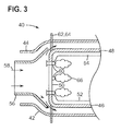
- FIG. 3 illustrates another exemplary configuration of another low-emission combustor 40 employed in the gas turbine 10 of FIG. 1.
- the combustor 40 includes an annular combustor.
- an inner casing 42 and an outer casing 44 define the combustion area within the combustor 40.
- the combustor 40 typically includes inner and outer combustor liners 46 and 48 and a dome plate 50.
- the combustor 40 includes inner and outer heat shields 52 and 54 disposed adjacent to the inner and outer combustor liners 46 and 48 and a diffuser section 56 for directing an airflow 58 inside the combustion area.
- the combustor 40 also includes a plurality of premixing devices 60 disposed upstream of the combustion area.
- a respective premixing device 60 receives fuel from a fuel plenum via fuel lines 62 and 64, which fuel is directed to flow over a pre-determined wall profile inside the premixing device 60 for enhancing the mixing efficiency of the premixing device 60 by entraining air using the Coanda effect. Further, the fuel from the fuel lines 62 and 64 is mixed with the incoming airflow 58 and a fuel-air mixture for combustion is delivered to flame 66.
- the introduction of fuel alters the air splits within the combustor 40. Particularly, the dilution air is substantially reduced and the combustion air split increases within the combustor 40 due to change in pressure generated by the Coanda effect.
- FIG. 4 is a cross-sectional view of an exemplary configuration of a premixing device 70 employed in the above-described combustors.
- the premixing device 70 includes an air inlet 72 configured to introduce compressed air into a mixing chamber 74.
- the premixing device 70 includes a fuel plenum 76 from which fuel is provided to the mixing chamber 74 via a converging-diverging fuel injection slot jet 90 disposed in a circumferential slot 78.
- the slot 78 may be continuously or discretely disposed around the circumference of the premixing device 70. The enlarged portion of FIG.
- FIG. 4 illustrates qualitatively the disposition of the converging-diverging fuel injection slot jet 90 in the slot 78.
- the enlarged portion of FIG. 4 has been rotated. Further details of the fuel injection slot jet 90 will be further explained below in conjunction with FIG. 5.
- the fuel introduced via the converging-diverging fuel injection slot jet 90 is deflected over a pre-determined wall profile 80, creating a fuel flow 82.
- the premixing device 70 has an annular configuration and the fuel is introduced radially in and across the pre-determined wall profile 80.
- the geometry and dimensions of the pre-determined wall profile 80 may be selected/optimized based upon a desired premixing efficiency and the operational conditions including factors such as, but not limited to, fuel pressure, fuel temperature, temperature of incoming air, and fuel injection velocity.
- Examples of fuel include natural gas, high hydrogen gas, hydrogen, biogas, carbon monoxide and syngas. However, a variety of other fuels may be employed.
- the pre-determined wall profile 80 causes the introduced fuel to attach to the wall profile 80 by the Coanda effect, thus forming a fuel boundary layer.
- This fuel boundary layer facilitates air entrainment, thereby enhancing the mixing efficiency within the mixing chamber 74 of the premixing device 70.
- the incoming air is introduced in the premixing device 70 via the air inlet 72.
- the flow of air may be introduced through a plurality of air inlets that are disposed upstream or downstream of the circumferential slot 78 to facilitate mixing of the air and fuel within the mixing chamber 74.
- the fuel may be injected at multiple locations through a plurality of slots along the length of the premixing device 70.
- the premixing device 70 may include a swirler (not shown) disposed upstream of the device 70 for providing a swirl movement in the air introduced in the mixing chamber 74.
- a swirler (not shown) is disposed at the fuel inlet gap for introducing swirling movement to the fuel flow across the pre-determined wall profile 80.
- the air swirler may be placed at the same axial level and co-axial with the premixing device 70, at the outlet plane from the premixing device 70.
- the premixing device 70 also includes a diffuser 84 having a straight or divergent profile for directing the fuel-air mixture formed in the mixing chamber 74 to the combustion section via an outlet 86.
- the angle for the diffuser 84 is in a range of about +/- 0 degrees to about 25 degrees.
- the degree of premixing of the premixing device 70 is controlled by a plurality of factors such as, but not limited to, the fuel type, geometry of the pre-determined wall profile 80, degree of pre-swirl of the air, size of the circumferential slot 78, fuel pressure, fuel temperature, temperature of incoming air, length and angle of the diffuser 84 and fuel injection velocity.
- the pre-determined wall profile 80 facilitates the formation of a fuel boundary layer along the diffuser 84 while a portion of the airflow from the air inlet 72 is entrained by the fuel boundary layer to form a shear layer for promoting the mixing of the incoming air, or oxidizer, and fuel.
- the fuel is supplied at a pressure relatively higher than the pressure of the incoming air. In one embodiment, the fuel pressure is about 1% to about 25% greater than the pressure of the incoming air at the air inlet 72.
- the above-described fuel boundary layer is formed by a Coanda effect.
- the fuel flow 82 attaches to the wall profile 80 and remains attached even when the surface of the wall profile 80 curves away from the initial fuel flow direction. More specifically, as the fuel flow accelerates around the wall profile 80 there is a pressure difference across the flow, which deflects the fuel flow 82 closer to the surface of the wall profile 80. As the fuel flow 82 moves across the wall profile 80, a certain amount of skin friction occurs between the fuel flow 82 and the wall profile 80. This resistance to the flow deflects the fuel flow 82 towards the wall profile 80, thereby causing it to remain close to the wall profile 80.
- the structural features of the converging-diverging fuel injection slot jet 90 disposed in the premixing device 70 are illustrated in FIG. 5.
- This converging-diverging fuel injection slot jet 90 serves to create a flow separation region 112 laterally inside the slot prior to injection into the oxidizer stream.
- the flow in the separation region 112 forces the fuel to expand and create mixing turbulence, thereby enhancing the mixing of fuel with the free stream flow of oxidizer in the mixing chamber.
- the converging-diverging fuel injection slot jet 90 includes a fuel inlet 92, a fuel outlet 94, a top wall 96, a bottom wall 98, and sidewalls 100.
- the height 102 of the converging-diverging fuel slot jet 90 measured in a direction perpendicular to the direction 101 of fuel flow is substantially constant along the length 104 of the slot jet 90, while the sidewalls 100 are shaped laterally so as to form a converging portion 106 from the inlet 92 to a throat 108 and a diverging portion 110 extending downstream of the throat 108 to the outlet 94.
- the fuel is first accelerated in the converging portion 106 of the converging-diverging slot jet 90 toward the throat 108 followed by an over-expansion in the diverging portion 110 of the slot, thereby creating the flow separation region 112 laterally inside the slot prior to injection into the oxidizer stream at the outlet 94.
- separation occurs inside the slot, forcing the fuel to expand and create mixing turbulence.
- the increased level of turbulence created by the localized separation of the flow at 112 will increase the level of mixing of the injected fuel with the free stream flow of oxidizer at the outlet 94 of the converging-diverging fuel injection slot jet 90.
- the additional turbulence generated by the localized separation region 112 enhances the mixing of fuel and oxidizer in the region outside the slot outlet 94 while still avoiding the liftoff of the fuel jet as the same exits the slot.
- the geometry for the fuel injection passages is configured to promote mixing of the fuel and oxidizer from the exit of the slot jets, due at least to the fluid dynamics occurring inside the slot jet geometry.
- the slot have a converging portion 106.
- a throat region is normally formed so as to allow for metering the flow and preventing any flashback and a converging-diverging slot may be easier to manufacture and possess reduced flow losses.
- the inlet of the slot could be a constant cross section for some length, followed by the divergent portion.
- the entry of the slot could also be rounded, which in effect would serve as a throat.
- the divergence angle ⁇ of the converging-diverging fuel injection slot jet 90 is large enough to cause the separation region 112 to be contained inside the slot, but not to extend beyond the outlet 94, as illustrated in FIG. 5.
- the divergence angle ⁇ is 20° or greater on each of the two sidewalls 100 of the slot jet 90.
- the length 114 of the divergent section is selected so as to assure that any separation bubbles are washed out before the outlet 94 of the slot jet 90.
- the diverging section may have curved walls that increase divergence with axial distance from the throat 108.
- the ratio of the stagnation pressure at the inlet 92 to the static pressure at the outlet 94 may vary from about 1.2 to 1.8. In another embodiment that ratio is preferably 1.5.
- the top wall 94 of the converging-diverging fuel injection slot jet 90 forms a continuous surface with the wall profile 80 of the premixing device 70 so as to allow the fuel to be injected nearly tangentially with the accelerating mainstream flow of oxidizer along the surface that creates the Coanda effect.
- a higher level of turbulence generated by the localized separation region 112 inside the converging-diverging fuel injection slot jet 90 is introduced into the fuel, thus increasing the mixing of the fuel and oxidizer.
- FIG. 6 illustrates a first exemplary embodiment in which the sidewalls 100 are made rough along the divergent portion 110 in order to promote additional mixing, while reducing the likelihood that the separation region 112 will extend beyond the outlet 94.
- the sidewalls 100 are jagged along the divergent portion 110, and, in FIG. 8, the sidewalls are stepped along the divergent portion 110.
- FIGS. 6-8 Those of ordinary skill in the applicable arts will understand that other embodiments of the divergent portion to generate turbulence or small disruptions in the flow along those surfaces are within the scope of the disclosed invention besides the three exemplary illustrations shown in FIGS. 6-8.
- the fuel injected along the Coanda surface contains an enhanced level of turbulence generated by the converging-diverging fuel injection slot jet 90, thus more efficiently mixing with the oxidizer in a short distance while the potential for fuel separation and consequent auto-ignition or flame holding inside the mixing chamber is minimized and/or eliminated.
- the geometry for the fuel injection passages are such that the mixing of the fuel and oxidizer from the exit of the slot jets is further promoted by the fluid dynamics occurring inside the slot jet geometry, thus helping the achievement of an increased level of fuel-air mixedness in a short length, without liftoff or separation of the fuel along the injection surface or the diffuser wall of the mixing chamber.
- the disclosed invention covers a broad range of converging-diverging injection slot types that may be integrated with the Coanda surfaces of the premixing devices, resulting on an improved performance as compared to conventional discrete jet injection using round jets in cross flow.
- the premixing device 70 may also include a continuous fuel inlet slot, in which a plurality of adjacent internal converging-diverging fuel injection slot jets are disposed, as illustrated in FIG. 9.
- each one of the converging-diverging slots illustrated in FIG. 9 may also include the above-described sidewall modifications so as to further enhance the development of turbulence as just explained.
- this junction should either meet within the divergent section to allow the separation to occur before the fuel and oxidizer meet, or the junction should be formed having a small radius feature, or sharp edge, such that no separation region can form.
- a sharp junction could be made inside, at the slot exit, or even after the slot exit.
- the converging-diverging fuel injection slot jet 90 of the instant invention may be formed as separate parts to be assembled into the premixing device 70.
- the slot jets 90 may also be formed as an integral part of the premixing device 70.
- the converging-diverging fuel injection slot jets are cast as an integral part of the premixing device 70.
- a gas-to-liquid system includes an air separation unit, a gas processing unit and a combustor.
- the air separation unit separates oxygen from air and the gas-processing unit prepares natural gas for conversion in the combustor.
- the oxygen from the air separation unit and the natural gas from the gas-processing unit are directed to the combustor where the natural gas and the oxygen are reacted at an elevated temperature and pressure to produce a synthesis gas.
- the premixing device is coupled to the combustor to facilitate the premixing of oxygen and the natural gas prior to reaction in the combustor.
- at least one surface of the premixing device has a pre-determined profile, wherein the pre-determined profile deflects the oxygen to facilitate attachment of the oxygen to the profile to form a boundary layer, the converging-diverging slot jets generate localized turbulence without inducing a boundary layer flow separation inside of the mixing chamber, and the boundary layer entrains incoming natural gas to enable the mixing of the natural gas and oxygen at high fuel-to-oxygen equivalence ratios (e.g. about 3.5 up to about 4 and beyond) to maximize syngas production yield while minimizing residence time.
- steam may be added to the oxygen or the fuel to enhance the process efficiency.
- the synthesis gas is then quenched and introduced into a Fischer-Tropsh processing unit, where through catalysis, the hydrogen gas and carbon monoxide are recombined into long-chain liquid hydrocarbons. Finally, the liquid hydrocarbons are converted and fractionated into products in a cracking unit.
- the premixing device based on the Coanda effect combined with the converging-diverging slot jets to generate localized turbulence without inducing a boundary layer flow separation inside of the mixing chamber induces rapid premixing of the natural gas and oxygen and a substantially short residence time in the gas to liquid system.
- the various aspects of the method described hereinabove have utility in different applications such as combustors employed in gas turbines and heating devices, such as furnaces. Furthermore, the technique described here enhances the premixing of fuel and air prior to combustion, thereby substantially reducing emissions and enhancing the efficiency of systems like gas turbines and appliance gas burners.
- the premixing technique can be employed for different fuels such as, but not limited to, gaseous fossil fuels of high and low volumetric heating values including natural gas, hydrocarbons, carbon monoxide, hydrogen, biogas and syngas.
- the premixing device may be employed in fuel flexible combustors for integrated gasification combined cycle (IGCC) for reducing pollutant emissions.
- IGCC integrated gasification combined cycle
- the premixing device may be employed in gas range appliances.
- the premixing device is employed in aircraft engine hydrogen combustors and other gas turbine combustors for aero-derivatives and heavy-duty machines.
- the premixing device described may facilitate substantial reduction in emissions for systems that employ fuel types ranging from low British Thermal Unit (BTU) to high hydrogen and pure hydrogen Wobbe indices.
- the premixing device may be utilized to facilitate partial mixing of streams such as oxy-fuel that will be particularly useful for carbon dioxide free cycles and exhaust gas recirculation.
- the premixing technique based upon the Coanda effect described above enables enhanced premixing and flame stabilization in a combustor. Further, the present technique enables reduction of emissions, particularly NO x emissions from such combustors, thereby facilitating the operation of the gas turbine in an environmentally friendly manner. In certain embodiments, this technique facilitates minimization of pressure drop across the combustors, more particularly in hydrogen combustors. In addition, the enhanced premixing achieved through the Coanda effect facilitates enhanced turndown (i.e., the ratio of the a burner's maximum firing capability to the burner's minimum firing capability), flashback resistance and increased flameout margin for the combustors.
- the fuel boundary layer is positioned along the walls via the Coanda effect resulting in substantially higher level of fuel concentration at the wall including at the outlet plane of the premixing device.
- the turndown benefits from the presence of the higher concentration of fuel at the wall, thereby stabilizing the flame.
- the absence of a flammable mixture next to the wall and the presence of 100% fuel at the walls determine the absence of the flame in that region, thereby increasing flashback resistance.
- the flame is kept away from the walls, thus allowing better turndown and permitting operation on natural gas and air mixtures having an equivalence ratio as low as about 0.2. Additionally, the flameout margin is significantly improved as compared to existing systems.
- this system may be used with a variety of fuels, thus providing enhanced fuel flexibility.
- the system may employ either natural gas or H 2 , for instance, as the fuel.
- the fuel flexibility of such system eliminates the need of hardware changes or complicated architectures with different fuel ports required for different fuels.
- the described premixing devices may be employed with a variety of fuels, thus providing fuel flexibility of the system.
- the technique described above may be employed in the existing can or can-annular combustors to reduce emissions and any dynamic oscillations and modulation within the combustors.
- the illustrated device may be employed as a pilot in existing combustors.
- Methods for premixing a fuel and an oxidizer in a combustion system are also within the scope of the embodiments of the invention disclosed, such methods including the steps of drawing the oxidizer inside a premixing device through an oxidizer inlet, injecting the fuel into the premixing device through a converging-diverging fuel injection slot jet, deflecting the injected fuel towards a pre-determined wall profile within the premixing device to form a fuel boundary layer along an inside wall of the premixing device, and premixing the fuel and oxidizer to form a fuel-air mixture, wherein the premixing includes over expanding the fuel in a diverging portion of the converging-diverging fuel injection slot jet to create a flow separation region in the diverging portion, the flow separation region being confined to the diverging portion and being configured to generate mixing turbulence at an outlet of the converging-diverging fuel injection slot jet to aerodynamically enhance a mixing of the fuel from the boundary layer with the oxidizer without causing a boundary layer flow separation and
Landscapes
- Engineering & Computer Science (AREA)
- Chemical & Material Sciences (AREA)
- Combustion & Propulsion (AREA)
- Mechanical Engineering (AREA)
- General Engineering & Computer Science (AREA)
Applications Claiming Priority (1)
| Application Number | Priority Date | Filing Date | Title |
|---|---|---|---|
| US11/558,760 US7832212B2 (en) | 2006-11-10 | 2006-11-10 | High expansion fuel injection slot jet and method for enhancing mixing in premixing devices |
Publications (2)
| Publication Number | Publication Date |
|---|---|
| EP1921377A2 true EP1921377A2 (fr) | 2008-05-14 |
| EP1921377A3 EP1921377A3 (fr) | 2013-12-25 |
Family
ID=38961175
Family Applications (1)
| Application Number | Title | Priority Date | Filing Date |
|---|---|---|---|
| EP07119876.6A Withdrawn EP1921377A3 (fr) | 2006-11-10 | 2007-11-02 | Jet à fente pour l'injection de carburant à haute expansion et procédé d'amélioration du mélange dans les dispositifs de prémélange |
Country Status (5)
| Country | Link |
|---|---|
| US (1) | US7832212B2 (fr) |
| EP (1) | EP1921377A3 (fr) |
| JP (1) | JP4831364B2 (fr) |
| KR (1) | KR101041705B1 (fr) |
| CN (1) | CN101201176B (fr) |
Cited By (2)
| Publication number | Priority date | Publication date | Assignee | Title |
|---|---|---|---|---|
| CN102486311A (zh) * | 2010-11-30 | 2012-06-06 | 通用电气公司 | 针对用于增强的火焰稳定抗力的预混合器尾流和旋涡填充的系统和方法 |
| CN110805503A (zh) * | 2018-08-06 | 2020-02-18 | 通用电气公司 | 具有旋转爆震燃烧系统的冲压喷气发动机及操作方法 |
Families Citing this family (36)
| Publication number | Priority date | Publication date | Assignee | Title |
|---|---|---|---|---|
| US8266911B2 (en) * | 2005-11-14 | 2012-09-18 | General Electric Company | Premixing device for low emission combustion process |
| KR101020596B1 (ko) * | 2008-09-11 | 2011-03-09 | 서울대학교산학협력단 | 연소기 및 이를 포함하는 엔진 |
| US8857733B1 (en) * | 2009-01-14 | 2014-10-14 | Resodyn Corporation | Flameless thermal spray system using flame heat source |
| US9140454B2 (en) * | 2009-01-23 | 2015-09-22 | General Electric Company | Bundled multi-tube nozzle for a turbomachine |
| US8763400B2 (en) * | 2009-08-04 | 2014-07-01 | General Electric Company | Aerodynamic pylon fuel injector system for combustors |
| JP5084847B2 (ja) * | 2010-01-13 | 2012-11-28 | 株式会社日立製作所 | ガスタービン燃焼器 |
| US20110197587A1 (en) * | 2010-02-18 | 2011-08-18 | General Electric Company | Multi-tube premixing injector |
| US8863525B2 (en) | 2011-01-03 | 2014-10-21 | General Electric Company | Combustor with fuel staggering for flame holding mitigation |
| US9068750B2 (en) * | 2011-03-04 | 2015-06-30 | General Electric Company | Combustor with a pre-nozzle mixing cap assembly |
| US8899494B2 (en) | 2011-03-31 | 2014-12-02 | General Electric Company | Bi-directional fuel injection method |
| DE102011102882A1 (de) * | 2011-05-31 | 2012-12-06 | Audag Ag | Vorrichtung zur Befeuchtung eines Trägermediums, wie eine Papierbahn |
| US9127622B2 (en) | 2011-11-21 | 2015-09-08 | United Technologies Corporation | Reversible flow discharge orifice |
| US9121612B2 (en) * | 2012-03-01 | 2015-09-01 | General Electric Company | System and method for reducing combustion dynamics in a combustor |
| US9267690B2 (en) | 2012-05-29 | 2016-02-23 | General Electric Company | Turbomachine combustor nozzle including a monolithic nozzle component and method of forming the same |
| JP6028578B2 (ja) * | 2013-01-15 | 2016-11-16 | 株式会社Ihi | 燃焼器 |
| KR101320406B1 (ko) * | 2013-01-17 | 2013-10-23 | 한국기계연구원 | 코안다 효과를 이용한 고온 FGR 초저 NOx 연소장치 |
| US20180231256A1 (en) * | 2017-02-10 | 2018-08-16 | General Electric Company | Rotating Detonation Combustor |
| KR101889542B1 (ko) * | 2017-04-18 | 2018-08-17 | 두산중공업 주식회사 | 연소기 노즐 조립체 및 이를 포함하는 가스터빈 |
| DE102018122628B4 (de) | 2017-09-29 | 2023-08-03 | Taiwan Semiconductor Manufacturing Co., Ltd. | CMOS Bildsensor mit gezackter Fotodiodenstruktur |
| US10790321B2 (en) | 2017-09-29 | 2020-09-29 | Taiwan Semiconductor Manufacturing Co., Ltd. | CMOS image sensor having indented photodiode structure |
| US20190242582A1 (en) * | 2018-02-07 | 2019-08-08 | General Electric Company | Thermal Attenuation Structure For Detonation Combustion System |
| US10837643B2 (en) * | 2018-08-06 | 2020-11-17 | General Electric Company | Mixer assembly for a combustor |
| FR3089851B1 (fr) * | 2018-12-12 | 2020-12-18 | Addup | Chambre de fabrication pour une machine de fabrication additive |
| US11073114B2 (en) * | 2018-12-12 | 2021-07-27 | General Electric Company | Fuel injector assembly for a heat engine |
| CN110778415B (zh) * | 2019-10-29 | 2022-01-14 | 哈尔滨工业大学(威海) | 一种航空发动机 |
| US11828467B2 (en) * | 2019-12-31 | 2023-11-28 | General Electric Company | Fluid mixing apparatus using high- and low-pressure fluid streams |
| KR102490478B1 (ko) * | 2021-02-03 | 2023-01-19 | 두산에너빌리티 주식회사 | 분사노즐, 연소기 및 이를 포함하는 가스터빈 |
| CN113090946B (zh) * | 2021-04-06 | 2022-04-05 | 西南石油大学 | 一种促进掺氢天然气管道内天然气与氢气混合的蚌式管道结构 |
| US11454396B1 (en) * | 2021-06-07 | 2022-09-27 | General Electric Company | Fuel injector and pre-mixer system for a burner array |
| US11543130B1 (en) * | 2021-06-28 | 2023-01-03 | Collins Engine Nozzles, Inc. | Passive secondary air assist nozzles |
| CN114308431B (zh) * | 2021-12-20 | 2023-02-17 | 江苏大学 | 一种叶轮换向脉冲喷头及喷洒方法 |
| US20240010350A1 (en) * | 2022-07-08 | 2024-01-11 | Rtx Corporation | Hybrid electric hydrogen engine for aircraft |
| US11867392B1 (en) | 2023-02-02 | 2024-01-09 | Pratt & Whitney Canada Corp. | Combustor with tangential fuel and air flow |
| US11867400B1 (en) | 2023-02-02 | 2024-01-09 | Pratt & Whitney Canada Corp. | Combustor with fuel plenum with mixing passages having baffles |
| US11873993B1 (en) | 2023-02-02 | 2024-01-16 | Pratt & Whitney Canada Corp. | Combustor for gas turbine engine with central fuel injection ports |
| US11835235B1 (en) | 2023-02-02 | 2023-12-05 | Pratt & Whitney Canada Corp. | Combustor with helix air and fuel mixing passage |
Citations (4)
| Publication number | Priority date | Publication date | Assignee | Title |
|---|---|---|---|---|
| US4073613A (en) * | 1974-06-25 | 1978-02-14 | The British Petroleum Company Limited | Flarestack Coanda burners with self-adjusting slot at pressure outlet |
| DE19729047C1 (de) * | 1997-07-08 | 1998-09-24 | Honeywell Bv | Mischvorrichtung zur Erzeugung eines Gemisches aus Gas und Verbrennungsluft für einen Brenner |
| EP0896192A2 (fr) * | 1997-08-05 | 1999-02-10 | Karl Dungs GmbH & Co. | Dispositif d'admission du gaz combustible pour un brûleur à prémélange |
| EP1609999A2 (fr) * | 2004-06-24 | 2005-12-28 | Rolls-Royce Deutschland Ltd & Co KG | Turbo machine |
Family Cites Families (14)
| Publication number | Priority date | Publication date | Assignee | Title |
|---|---|---|---|---|
| JPH018834Y2 (fr) * | 1984-12-28 | 1989-03-09 | ||
| US5103630A (en) * | 1989-03-24 | 1992-04-14 | General Electric Company | Dry low NOx hydrocarbon combustion apparatus |
| JPH06101841A (ja) * | 1992-09-21 | 1994-04-12 | Hitachi Ltd | ガスタービン燃焼器の空気−燃料予混合構造 |
| DE69625744T2 (de) * | 1995-06-05 | 2003-10-16 | Rolls Royce Corp | Magervormischbrenner mit niedrigem NOx-Ausstoss für industrielle Gasturbinen |
| DE69732341T2 (de) * | 1996-07-19 | 2006-05-18 | Babcock-Hitachi K.K. | Brenner |
| JP3344694B2 (ja) * | 1997-07-24 | 2002-11-11 | 株式会社日立製作所 | 微粉炭燃焼バーナ |
| JP2000039148A (ja) * | 1998-07-21 | 2000-02-08 | Mitsubishi Heavy Ind Ltd | ガスタービン燃焼器ノズル |
| JP2000274611A (ja) * | 1999-03-26 | 2000-10-03 | Hitachi Ltd | 燃焼器 |
| JP2001280641A (ja) * | 2000-03-31 | 2001-10-10 | Mitsubishi Heavy Ind Ltd | ガスタービン燃焼器、および、ガスタービン燃焼器における燃料と空気の混合方法 |
| US20020162333A1 (en) * | 2001-05-02 | 2002-11-07 | Honeywell International, Inc., Law Dept. Ab2 | Partial premix dual circuit fuel injector |
| JP2003035417A (ja) * | 2001-07-24 | 2003-02-07 | Mitsubishi Heavy Ind Ltd | ガスタービン燃焼器のパイロットノズル |
| US6865889B2 (en) * | 2002-02-01 | 2005-03-15 | General Electric Company | Method and apparatus to decrease combustor emissions |
| US6772595B2 (en) * | 2002-06-25 | 2004-08-10 | Power Systems Mfg., Llc | Advanced cooling configuration for a low emissions combustor venturi |
| WO2005082776A2 (fr) * | 2004-02-20 | 2005-09-09 | Sasol Technology (Proprietary) Limited | Fourniture de vapeur et d'hydrogene pour un processus ou une installation de production de gaz de synthese |
-
2006
- 2006-11-10 US US11/558,760 patent/US7832212B2/en not_active Expired - Fee Related
-
2007
- 2007-11-02 EP EP07119876.6A patent/EP1921377A3/fr not_active Withdrawn
- 2007-11-06 JP JP2007287978A patent/JP4831364B2/ja not_active Expired - Fee Related
- 2007-11-08 KR KR1020070113667A patent/KR101041705B1/ko not_active IP Right Cessation
- 2007-11-09 CN CN2007101694452A patent/CN101201176B/zh not_active Expired - Fee Related
Patent Citations (4)
| Publication number | Priority date | Publication date | Assignee | Title |
|---|---|---|---|---|
| US4073613A (en) * | 1974-06-25 | 1978-02-14 | The British Petroleum Company Limited | Flarestack Coanda burners with self-adjusting slot at pressure outlet |
| DE19729047C1 (de) * | 1997-07-08 | 1998-09-24 | Honeywell Bv | Mischvorrichtung zur Erzeugung eines Gemisches aus Gas und Verbrennungsluft für einen Brenner |
| EP0896192A2 (fr) * | 1997-08-05 | 1999-02-10 | Karl Dungs GmbH & Co. | Dispositif d'admission du gaz combustible pour un brûleur à prémélange |
| EP1609999A2 (fr) * | 2004-06-24 | 2005-12-28 | Rolls-Royce Deutschland Ltd & Co KG | Turbo machine |
Cited By (4)
| Publication number | Priority date | Publication date | Assignee | Title |
|---|---|---|---|---|
| CN102486311A (zh) * | 2010-11-30 | 2012-06-06 | 通用电气公司 | 针对用于增强的火焰稳定抗力的预混合器尾流和旋涡填充的系统和方法 |
| US9435537B2 (en) | 2010-11-30 | 2016-09-06 | General Electric Company | System and method for premixer wake and vortex filling for enhanced flame-holding resistance |
| CN102486311B (zh) * | 2010-11-30 | 2017-03-01 | 通用电气公司 | 针对用于增强的火焰稳定抗力的预混合器尾流和旋涡填充的系统和方法 |
| CN110805503A (zh) * | 2018-08-06 | 2020-02-18 | 通用电气公司 | 具有旋转爆震燃烧系统的冲压喷气发动机及操作方法 |
Also Published As
| Publication number | Publication date |
|---|---|
| US7832212B2 (en) | 2010-11-16 |
| JP2008122065A (ja) | 2008-05-29 |
| US20080110173A1 (en) | 2008-05-15 |
| JP4831364B2 (ja) | 2011-12-07 |
| CN101201176B (zh) | 2012-05-30 |
| KR20080042714A (ko) | 2008-05-15 |
| EP1921377A3 (fr) | 2013-12-25 |
| KR101041705B1 (ko) | 2011-06-14 |
| CN101201176A (zh) | 2008-06-18 |
Similar Documents
| Publication | Publication Date | Title |
|---|---|---|
| US7832212B2 (en) | High expansion fuel injection slot jet and method for enhancing mixing in premixing devices | |
| EP1923637B1 (fr) | Tourbillonneur annulaire triple à contre-rotation | |
| US20080104961A1 (en) | Method and apparatus for enhanced mixing in premixing devices | |
| US8266911B2 (en) | Premixing device for low emission combustion process | |
| US20080163627A1 (en) | Fuel-flexible triple-counter-rotating swirler and method of use | |
| US7874157B2 (en) | Coanda pilot nozzle for low emission combustors | |
| US8176739B2 (en) | Coanda injection system for axially staged low emission combustors | |
| US8015814B2 (en) | Turbine engine having folded annular jet combustor | |
| US20150176842A1 (en) | Method for operating a combustor for a gas turbine and combustor for a gas turbine | |
| KR20140082658A (ko) | 가스 터빈 엔진에서 사용되는 스테이지가 형성되고 접선방향으로 형성된 연료-공기 노즐을 가진 캔-애뉼러형 연소실 | |
| US20160265779A1 (en) | Twin radial splitter-chevron mixer with converging throat | |
| KR20140082659A (ko) | 가스 터빈 엔진에서 사용되는 예비혼합형 접선방향 연료-공기 노즐을 가진 캔-애뉼러형 연소실 | |
| WO2013028164A2 (fr) | Chambre de combustion annulaire tangentielle comprenant un prémélange d'air et de carburant destinée à être utilisée dans des moteurs à turbine à gaz | |
| KR102429643B1 (ko) | 가스 터빈의 연소 안정성 개선 시스템 및 방법 | |
| KR20140082657A (ko) | 가스 터빈 엔진에 사용되는 접선방향의 무염 애뉼러형 연소실 |
Legal Events
| Date | Code | Title | Description |
|---|---|---|---|
| PUAI | Public reference made under article 153(3) epc to a published international application that has entered the european phase |
Free format text: ORIGINAL CODE: 0009012 |
|
| AK | Designated contracting states |
Kind code of ref document: A2 Designated state(s): AT BE BG CH CY CZ DE DK EE ES FI FR GB GR HU IE IS IT LI LT LU LV MC MT NL PL PT RO SE SI SK TR |
|
| AX | Request for extension of the european patent |
Extension state: AL BA HR MK RS |
|
| PUAL | Search report despatched |
Free format text: ORIGINAL CODE: 0009013 |
|
| AK | Designated contracting states |
Kind code of ref document: A3 Designated state(s): AT BE BG CH CY CZ DE DK EE ES FI FR GB GR HU IE IS IT LI LT LU LV MC MT NL PL PT RO SE SI SK TR |
|
| AX | Request for extension of the european patent |
Extension state: AL BA HR MK RS |
|
| RIC1 | Information provided on ipc code assigned before grant |
Ipc: F23R 3/28 20060101ALI20131119BHEP Ipc: F23D 14/62 20060101AFI20131119BHEP |
|
| AKY | No designation fees paid | ||
| REG | Reference to a national code |
Ref country code: DE Ref legal event code: R108 |
|
| REG | Reference to a national code |
Ref country code: DE Ref legal event code: R108 Effective date: 20140903 |
|
| STAA | Information on the status of an ep patent application or granted ep patent |
Free format text: STATUS: THE APPLICATION IS DEEMED TO BE WITHDRAWN |
|
| 18D | Application deemed to be withdrawn |
Effective date: 20140626 |