EP1921320A2 - Scroll compressor with vapor injection and unloader port - Google Patents
Scroll compressor with vapor injection and unloader port Download PDFInfo
- Publication number
- EP1921320A2 EP1921320A2 EP07254203A EP07254203A EP1921320A2 EP 1921320 A2 EP1921320 A2 EP 1921320A2 EP 07254203 A EP07254203 A EP 07254203A EP 07254203 A EP07254203 A EP 07254203A EP 1921320 A2 EP1921320 A2 EP 1921320A2
- Authority
- EP
- European Patent Office
- Prior art keywords
- unloader
- economizer
- line
- port
- ports
- Prior art date
- Legal status (The legal status is an assumption and is not a legal conclusion. Google has not performed a legal analysis and makes no representation as to the accuracy of the status listed.)
- Granted
Links
Images
Classifications
-
- F—MECHANICAL ENGINEERING; LIGHTING; HEATING; WEAPONS; BLASTING
- F04—POSITIVE - DISPLACEMENT MACHINES FOR LIQUIDS; PUMPS FOR LIQUIDS OR ELASTIC FLUIDS
- F04C—ROTARY-PISTON, OR OSCILLATING-PISTON, POSITIVE-DISPLACEMENT MACHINES FOR LIQUIDS; ROTARY-PISTON, OR OSCILLATING-PISTON, POSITIVE-DISPLACEMENT PUMPS
- F04C28/00—Control of, monitoring of, or safety arrangements for, pumps or pumping installations specially adapted for elastic fluids
- F04C28/24—Control of, monitoring of, or safety arrangements for, pumps or pumping installations specially adapted for elastic fluids characterised by using valves controlling pressure or flow rate, e.g. discharge valves or unloading valves
- F04C28/26—Control of, monitoring of, or safety arrangements for, pumps or pumping installations specially adapted for elastic fluids characterised by using valves controlling pressure or flow rate, e.g. discharge valves or unloading valves using bypass channels
-
- F—MECHANICAL ENGINEERING; LIGHTING; HEATING; WEAPONS; BLASTING
- F04—POSITIVE - DISPLACEMENT MACHINES FOR LIQUIDS; PUMPS FOR LIQUIDS OR ELASTIC FLUIDS
- F04C—ROTARY-PISTON, OR OSCILLATING-PISTON, POSITIVE-DISPLACEMENT MACHINES FOR LIQUIDS; ROTARY-PISTON, OR OSCILLATING-PISTON, POSITIVE-DISPLACEMENT PUMPS
- F04C18/00—Rotary-piston pumps specially adapted for elastic fluids
- F04C18/02—Rotary-piston pumps specially adapted for elastic fluids of arcuate-engagement type, i.e. with circular translatory movement of co-operating members, each member having the same number of teeth or tooth-equivalents
-
- F—MECHANICAL ENGINEERING; LIGHTING; HEATING; WEAPONS; BLASTING
- F04—POSITIVE - DISPLACEMENT MACHINES FOR LIQUIDS; PUMPS FOR LIQUIDS OR ELASTIC FLUIDS
- F04C—ROTARY-PISTON, OR OSCILLATING-PISTON, POSITIVE-DISPLACEMENT MACHINES FOR LIQUIDS; ROTARY-PISTON, OR OSCILLATING-PISTON, POSITIVE-DISPLACEMENT PUMPS
- F04C29/00—Component parts, details or accessories of pumps or pumping installations, not provided for in groups F04C18/00 - F04C28/00
- F04C29/12—Arrangements for admission or discharge of the working fluid, e.g. constructional features of the inlet or outlet
- F04C29/124—Arrangements for admission or discharge of the working fluid, e.g. constructional features of the inlet or outlet with inlet and outlet valves specially adapted for rotary or oscillating piston pumps
- F04C29/126—Arrangements for admission or discharge of the working fluid, e.g. constructional features of the inlet or outlet with inlet and outlet valves specially adapted for rotary or oscillating piston pumps of the non-return type
- F04C29/128—Arrangements for admission or discharge of the working fluid, e.g. constructional features of the inlet or outlet with inlet and outlet valves specially adapted for rotary or oscillating piston pumps of the non-return type of the elastic type, e.g. reed valves
-
- F—MECHANICAL ENGINEERING; LIGHTING; HEATING; WEAPONS; BLASTING
- F04—POSITIVE - DISPLACEMENT MACHINES FOR LIQUIDS; PUMPS FOR LIQUIDS OR ELASTIC FLUIDS
- F04C—ROTARY-PISTON, OR OSCILLATING-PISTON, POSITIVE-DISPLACEMENT MACHINES FOR LIQUIDS; ROTARY-PISTON, OR OSCILLATING-PISTON, POSITIVE-DISPLACEMENT PUMPS
- F04C18/00—Rotary-piston pumps specially adapted for elastic fluids
- F04C18/02—Rotary-piston pumps specially adapted for elastic fluids of arcuate-engagement type, i.e. with circular translatory movement of co-operating members, each member having the same number of teeth or tooth-equivalents
- F04C18/0207—Rotary-piston pumps specially adapted for elastic fluids of arcuate-engagement type, i.e. with circular translatory movement of co-operating members, each member having the same number of teeth or tooth-equivalents both members having co-operating elements in spiral form
- F04C18/0215—Rotary-piston pumps specially adapted for elastic fluids of arcuate-engagement type, i.e. with circular translatory movement of co-operating members, each member having the same number of teeth or tooth-equivalents both members having co-operating elements in spiral form where only one member is moving
-
- F—MECHANICAL ENGINEERING; LIGHTING; HEATING; WEAPONS; BLASTING
- F04—POSITIVE - DISPLACEMENT MACHINES FOR LIQUIDS; PUMPS FOR LIQUIDS OR ELASTIC FLUIDS
- F04C—ROTARY-PISTON, OR OSCILLATING-PISTON, POSITIVE-DISPLACEMENT MACHINES FOR LIQUIDS; ROTARY-PISTON, OR OSCILLATING-PISTON, POSITIVE-DISPLACEMENT PUMPS
- F04C23/00—Combinations of two or more pumps, each being of rotary-piston or oscillating-piston type, specially adapted for elastic fluids; Pumping installations specially adapted for elastic fluids; Multi-stage pumps specially adapted for elastic fluids
- F04C23/008—Hermetic pumps
Definitions
- This application relates to a scroll compressor wherein one set of ports is utilized for both injecting vapor refrigerant into the compressor and for compressor unloading by directing vapor refrigerant from the compressor intermediate compression point to compressor suction, and wherein the other separate set of ports is utilized only for compressor unloading.
- first and second scroll members each have a base and a generally spiral wrap extending from the base.
- the wraps of the two scroll members interfit to define compression chambers.
- One of the two scroll members is caused to orbit relative to the other, and as they orbit relative to each other, refrigerant is trapped within compression chambers defined between the wraps.
- the size of these compression chambers is reduced and the entrapped refrigerant is compressed.
- the compressor when there is a reduced cooling capacity desired from a refrigerant system associated with the scroll compressor, the compressor may be "unloaded". When the compressor is unloaded, refrigerant may be tapped from the compression chambers through an open unloader valve and back to a suction port leading into the compressor. In this manner, the amount of compressed refrigerant is reduced, and the capacity of the associated refrigerant system is similarly reduced.
- an economizer cycle may be actuated.
- refrigerant downstream of a condenser is tapped from a main refrigerant flow line and the tapped refrigerant is expanded.
- the tapped refrigerant passes in a heat transfer relationship with the main refrigerant line in an economizer heat exchanger, thereby sub-cooling the main refrigerant flow.
- the tapped refrigerant is injected into an intermediate compression port or set of ports in the compressor.
- the economizer injection passage is also connected to the unloader line which selectively communicates the economizer injection passage back to the suction line.
- the economizer injection passage can be kept open or shutoff, with the shut off device installed in the economizer line between the condenser and the unloader line.
- Separate flow control devices control the operation of both the economizer function and the unloader.
- a single passage communicates through a compressor shell, and into a passage in non-orbiting scroll member.
- the passage leads to both economizer ports, and bypass ports which extend through a base of the non-orbiting scroll member to communicate with the compression chambers.
- the economizer ports are preferably positioned more adjacent a mid-way portion of the compression cycle (however under some circumstances it might be more desirable to position them closer to the suction side), while the separate bypass holes are positioned closer to the suction side.
- the bypass holes are preferably of a larger cross-sectional area than the economizer holes.
- bypass holes are preferably associated with the check valve such that the vapor being injected into the economizer injection holes does not pass into the bypass holes.
- the by-pass flow can pass through an injection port and by-pass dedicated port (when the flow is by-passed the check valve is open). In this case the by-pass process is further optimized because the amount of by-pass flow is further increased as the by-pass flow can pass through both of these openings.
- the scroll compressor designers can design the size and location of the ports to be optimum for each function.
- a refrigerant system 20 is illustrated in Figure 1 having a compressor 19 with a compressor shell 21.
- the compressor is a scroll compressor having an orbiting scroll member 22 and a non-orbiting scroll member 24.
- a suction line 26 delivers a refrigerant into a chamber 31 within the compressor shell 21.
- refrigerant is compressed between the orbiting scroll member 22 and non-orbiting scroll member 24, and delivered outwardly of the shell 21 through a discharge line 28.
- An economizer injection line 30 communicates with a passage 32 extending through a base of the non-orbiting scroll member 24.
- a line 34 communicates the passage 30 back to the suction line 26.
- An unloader valve 36 positioned on this line 34 selectively blocks or allows refrigerant to flow from the compression chamber outwardly and back into the suction line 26.
- a condenser 100 is positioned downstream of discharge port 28.
- a tap 102 taps a portion of a refrigerant from a main refrigerant line 103, and expands that tapped refrigerant in an expansion device 105.
- the tapped refrigerant passes in heat transfer relationship with the refrigerant in the main flow line 103 in an economizer heat exchanger 104.
- the tapped refrigerant is returned back through a valve 106 and into the line through the passage 30. While the flow of the tapped refrigerant 102 and main refrigerant flow 103 are shown in the same direction through the economizer heat exchanger 104, in practice they may be in counter-flow directions.
- the main refrigerant flow line Downstream of the economizer heat exchanger 104, the main refrigerant flow line passes through an expansion device 108, an evaporator 110, and back to the suction line 26.
- the passage 32 communicates with economizer injection ports 200.
- economizer injection ports 200 there are can be a pair (or multiple ports) of ports 200 or a single port associated with two distinct locations in the base of the non-orbiting scroll 24.
- unloader ports 202 are shown in this figure. As shown in this Figure, the locations of the ports 202 are closer to the outer portions of the wraps of the orbiting and non-orbiting scroll members, and thus closer to a suction location than are the economizer holes 200.
- the by-pass unloader ports can be exposed to both chamber 31 at suction pressure as well as partially compressed gas between the fixed scroll 24 and orbiting scroll 22. If the by-pass unloader ports are positioned further into the compression process, they may be only exposed to the partially compressed refrigerant and be essentially isolated form the chamber 31.
- the unloader holes 202 are associated with a valve stop 204, bolt 210 holding the valve stop 204, and a reed valve 206.
- the pressure inside the scroll elements is higher then the suction pressure, which opens the reed valve and permits a portion of the flow from the scroll compression pockets to by-pass back to suction through passages 202.
- Some additional flow is also by-passed through open passages 200, which are always open.
- pressure in the economized passage is higher then pressure inside the scroll compression pockets, thus the reed valve is closed preventing vapor injection from being injected through the blocked off passages 202.
- the vapor is then only injected through passages 200, whose size and location is specifically selected to optimize the amount of vapor-injected flow.
- the present invention is able to provide an optimum design for these types of operation.
- the prior art compromises as set forth above are thus eliminated.
Landscapes
- Engineering & Computer Science (AREA)
- Mechanical Engineering (AREA)
- General Engineering & Computer Science (AREA)
- Physics & Mathematics (AREA)
- Fluid Mechanics (AREA)
- Rotary Pumps (AREA)
Abstract
Description
- This application relates to a scroll compressor wherein one set of ports is utilized for both injecting vapor refrigerant into the compressor and for compressor unloading by directing vapor refrigerant from the compressor intermediate compression point to compressor suction, and wherein the other separate set of ports is utilized only for compressor unloading.
- Scroll compressors are becoming widely utilized in refrigerant compression applications. In a scroll compressor, first and second scroll members each have a base and a generally spiral wrap extending from the base. The wraps of the two scroll members interfit to define compression chambers. One of the two scroll members is caused to orbit relative to the other, and as they orbit relative to each other, refrigerant is trapped within compression chambers defined between the wraps. As the orbiting scroll moves through an orbiting cycle, the size of these compression chambers is reduced and the entrapped refrigerant is compressed.
- There are many optional features which are utilized in refrigerant compression applications, and in scroll compressors. In one optional feature, when there is a reduced cooling capacity desired from a refrigerant system associated with the scroll compressor, the compressor may be "unloaded". When the compressor is unloaded, refrigerant may be tapped from the compression chambers through an open unloader valve and back to a suction port leading into the compressor. In this manner, the amount of compressed refrigerant is reduced, and the capacity of the associated refrigerant system is similarly reduced.
- In another optional feature, when additional capacity is desired, an economizer cycle may be actuated. With an economizer cycle, refrigerant downstream of a condenser is tapped from a main refrigerant flow line and the tapped refrigerant is expanded. The tapped refrigerant passes in a heat transfer relationship with the main refrigerant line in an economizer heat exchanger, thereby sub-cooling the main refrigerant flow. The tapped refrigerant is injected into an intermediate compression port or set of ports in the compressor.
- There is a prior art construction which provides both the unloader and economizer functions through to the same flow passage in the non-orbiting scroll member. In this structure, the economizer injection passage is also connected to the unloader line which selectively communicates the economizer injection passage back to the suction line. The economizer injection passage can be kept open or shutoff, with the shut off device installed in the economizer line between the condenser and the unloader line. Separate flow control devices control the operation of both the economizer function and the unloader. To perform vapor injection economized function or by-pass of the flow back to suction, there is normally a passage that extends through the base of the non-orbiting scroll, and into ports leading into the compression chambers.
- In the prior art, there have been compromises with regard to the size and position of these ports. For optimum economizer operation (vapor injection), it is desirable to have relatively small ports. If the ports for injection are selected to be too large, the efficiency of the compression cycle would drop off. On the other hand, for optimum unloader operation, it is normally desirable to select the ports to be as large as possible as permitted by the compressor dimensional envelope.
- Thus, in the prior art, there have been compromises between these two goals, when selecting the size of these ports, since the same ports were used for both vapor injection and by-pass unloading operation.
- In the disclosed embodiment of this invention, a single passage communicates through a compressor shell, and into a passage in non-orbiting scroll member. The passage leads to both economizer ports, and bypass ports which extend through a base of the non-orbiting scroll member to communicate with the compression chambers. The economizer ports are preferably positioned more adjacent a mid-way portion of the compression cycle (however under some circumstances it might be more desirable to position them closer to the suction side), while the separate bypass holes are positioned closer to the suction side. The bypass holes are preferably of a larger cross-sectional area than the economizer holes. Having a larger size by-pass ports optimizes compressor performance at by-pass unloading operation, as larger ports permit more flow to by-pass back to suction than smaller ports. Also the parasitic throttling flow losses are reduced with larger by-pass ports. Further, the bypass holes are preferably associated with the check valve such that the vapor being injected into the economizer injection holes does not pass into the bypass holes. However the by-pass flow can pass through an injection port and by-pass dedicated port (when the flow is by-passed the check valve is open). In this case the by-pass process is further optimized because the amount of by-pass flow is further increased as the by-pass flow can pass through both of these openings.
- With the present invention, the scroll compressor designers can design the size and location of the ports to be optimum for each function.
- These and other features of the present invention can be best understood from the following specification and drawings, the following of which is a brief description.
-
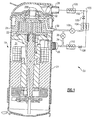
- Figure 1 is a cross-sectional view of a scroll compressor incorporating the present invention.
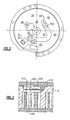
- Figure 2 is a top view of the non-orbiting scroll according to the present invention.
- Figure 3 shows another feature of the present invention.
- A
refrigerant system 20 is illustrated in Figure 1 having acompressor 19 with acompressor shell 21. The compressor is a scroll compressor having an orbitingscroll member 22 and anon-orbiting scroll member 24. Asuction line 26 delivers a refrigerant into achamber 31 within thecompressor shell 21. As known, refrigerant is compressed between the orbitingscroll member 22 andnon-orbiting scroll member 24, and delivered outwardly of theshell 21 through adischarge line 28. Aneconomizer injection line 30 communicates with apassage 32 extending through a base of thenon-orbiting scroll member 24. As further shown, aline 34 communicates thepassage 30 back to thesuction line 26. Anunloader valve 36 positioned on thisline 34 selectively blocks or allows refrigerant to flow from the compression chamber outwardly and back into thesuction line 26. - A
condenser 100 is positioned downstream ofdischarge port 28. Atap 102 taps a portion of a refrigerant from amain refrigerant line 103, and expands that tapped refrigerant in anexpansion device 105. The tapped refrigerant passes in heat transfer relationship with the refrigerant in themain flow line 103 in aneconomizer heat exchanger 104. The tapped refrigerant is returned back through avalve 106 and into the line through thepassage 30. While the flow of the tappedrefrigerant 102 andmain refrigerant flow 103 are shown in the same direction through theeconomizer heat exchanger 104, in practice they may be in counter-flow directions. - Downstream of the
economizer heat exchanger 104, the main refrigerant flow line passes through anexpansion device 108, anevaporator 110, and back to thesuction line 26. - As shown in Figures 1 and 2, the
passage 32 communicates witheconomizer injection ports 200. As shown in Figure 2, there are can be a pair (or multiple ports) ofports 200 or a single port associated with two distinct locations in the base of thenon-orbiting scroll 24. Further,unloader ports 202 are shown in this figure. As shown in this Figure, the locations of theports 202 are closer to the outer portions of the wraps of the orbiting and non-orbiting scroll members, and thus closer to a suction location than are theeconomizer holes 200. As the orbiting scroll orbits, the by-pass unloader ports can be exposed to bothchamber 31 at suction pressure as well as partially compressed gas between thefixed scroll 24 and orbitingscroll 22. If the by-pass unloader ports are positioned further into the compression process, they may be only exposed to the partially compressed refrigerant and be essentially isolated form thechamber 31. - As shown in Figure 3, the
unloader holes 202 are associated with avalve stop 204,bolt 210 holding thevalve stop 204, and areed valve 206. During the unloading operation, the pressure inside the scroll elements is higher then the suction pressure, which opens the reed valve and permits a portion of the flow from the scroll compression pockets to by-pass back to suction throughpassages 202. Some additional flow is also by-passed throughopen passages 200, which are always open. On the other hand when the vapor injection process is engaged, pressure in the economized passage is higher then pressure inside the scroll compression pockets, thus the reed valve is closed preventing vapor injection from being injected through the blocked offpassages 202. The vapor is then only injected throughpassages 200, whose size and location is specifically selected to optimize the amount of vapor-injected flow. - By utilizing the dual port arrangement, where a check valve covers one set of ports, the present invention is able to provide an optimum design for these types of operation. The prior art compromises as set forth above are thus eliminated.
- Although a preferred embodiment of this invention has been disclosed, a worker of ordinary skill in this art would recognize that certain modifications would come within the scope of this invention. For that reason, the following claims should be studied to determine the true scope and content of this invention.
Claims (9)
- A scroll compressor comprising:a first scroll member having a base and a generally spiral wrap extending from its base;a second scroll member having a base and a generally spiral wrap extending from its base, the base of said first and second scroll members interfitting to define compression chambers, said second scroll member being driven to orbit relative to said first scroll member;a suction line for communicating refrigerant into a compressor shell for said compressor, and a discharge line for communicating refrigerant outwardly of said shell;an economizer injection line for injecting a vapor refrigerant back into the compression chambers from an economizer circuit, said economizer injection line passing through said base of said first scroll member and communicating with at least one economizer port for injecting the vapor refrigerant into said compression chambers; andan unloader line for selectively communicating said economizer injection line back to said suction line, said unloader line being associated with an unloader valve, and at least one unloader port being provided in said non-orbiting scroll and when said unloader valve is opened, to communicate refrigerant from said compression chambers through said unloader port, into said economizer injection line, into said unloader line and to said suction line, said unloader port and said economizer port being distinct ports.
- The scroll compressor as set forth in Claim 1, wherein said economizer port is positioned further into a compression cycle than is said unloader port.
- The scroll compressor as set forth in Claim 2, wherein there are two of said unloader ports, and two of said economizer ports.
- The scroll compressor as recited in any preceding claim, wherein a check valve closes off flow from said economizer injection line into said compression chambers through said unloader port, said check valve opens to allow flow of refrigerant from said compression chambers, through said unloader port, and into said economizer injection line.
- The scroll compressor as recited in any preceding claim, wherein said at least one economizer port is of a smaller cross-sectional area than at least one said unloader port.
- The scroll compressor as recited in any preceding claim, wherein said flow resistance of at least one of said economizer port is larger than flow resistance of at least one of said unloader ports.
- The scroll compressor as recited in any preceding claim, wherein when said unloader valve is open, refrigerant can also pass through said economizer port, into said economizer injection line, said unloader line and to said suction line.
- A scroll compressor comprising:a first scroll member having a base and a generally spiral wrap extending from its base;a second scroll member having a base and a generally spiral wrap extending from its base, the base of said first and second scroll members interfitting to define compression chambers, said second scroll member being driven to orbit relative to said first scroll member;a suction line for communicating refrigerant into a compressor shell for said compressor, and a discharge line for communicating refrigerant outwardly of said shell;an economizer injection line for injecting a vapor refrigerant back into the compression chambers from an economizer circuit, said economizer injection line passing through said base of said first scroll member and communicating with at least two economizer ports for injecting the vapor refrigerant into said compression chambers;an unloader line for selectively communicating said economizer injection line back to said suction line, said unloader line being associated with an unloader valve, unloader ports provided in said non-orbiting scroll and when said unloader valve is opened, to communicate refrigerant from said compression chambers through said unloader ports, into said economizer injection line, into said unloader line and to said suction line, said unloader ports and said economizer ports being distinct ports, said economizer port positioned further into a compression cycle than said unloader port, said economizer ports being of a smaller cross-sectional area than said unloader ports; anda check valve closing off flow from said economizer injection line into said compression chambers through said unloader port, said check valve opening to allow flow of refrigerant from said compression chambers, through said unloader port, and into said economizer injection line.
- The scroll compressor as recited in Claim 8, wherein when said unloader valve is open, refrigerant can also pass through said economizer port, into said economizer injection line, said unloader line and to said suction line.
Applications Claiming Priority (1)
| Application Number | Priority Date | Filing Date | Title |
|---|---|---|---|
| US11/593,732 US7674098B2 (en) | 2006-11-07 | 2006-11-07 | Scroll compressor with vapor injection and unloader port |
Publications (3)
| Publication Number | Publication Date |
|---|---|
| EP1921320A2 true EP1921320A2 (en) | 2008-05-14 |
| EP1921320A3 EP1921320A3 (en) | 2011-07-27 |
| EP1921320B1 EP1921320B1 (en) | 2012-10-17 |
Family
ID=39047170
Family Applications (1)
| Application Number | Title | Priority Date | Filing Date |
|---|---|---|---|
| EP07254203A Not-in-force EP1921320B1 (en) | 2006-11-07 | 2007-10-23 | Scroll compressor with vapor injection and unloader port |
Country Status (5)
| Country | Link |
|---|---|
| US (1) | US7674098B2 (en) |
| EP (1) | EP1921320B1 (en) |
| JP (1) | JP2008115865A (en) |
| KR (1) | KR20080041565A (en) |
| CN (1) | CN101178065B (en) |
Cited By (3)
| Publication number | Priority date | Publication date | Assignee | Title |
|---|---|---|---|---|
| FR2940373A1 (en) * | 2008-12-19 | 2010-06-25 | Danfoss Commercial Compressors | SPIRAL REFRIGERATING COMPRESSOR |
| CN103452840A (en) * | 2013-09-12 | 2013-12-18 | 安徽奥特佳科技发展有限公司 | Electric scroll compressor realizing two-stage compression and middle injection for automobile heat pump |
| EP3805564A1 (en) * | 2019-10-10 | 2021-04-14 | LG Electronics Inc. | Motor operated compressor |
Families Citing this family (24)
| Publication number | Priority date | Publication date | Assignee | Title |
|---|---|---|---|---|
| US7815423B2 (en) * | 2005-07-29 | 2010-10-19 | Emerson Climate Technologies, Inc. | Compressor with fluid injection system |
| CN102089525B (en) | 2008-05-30 | 2013-08-07 | 艾默生环境优化技术有限公司 | Compressor having output adjustment assembly including piston actuation |
| US8303278B2 (en) * | 2008-07-08 | 2012-11-06 | Tecumseh Products Company | Scroll compressor utilizing liquid or vapor injection |
| KR101056882B1 (en) * | 2009-01-07 | 2011-08-12 | 엘지전자 주식회사 | Scroll compressor |
| US7988433B2 (en) | 2009-04-07 | 2011-08-02 | Emerson Climate Technologies, Inc. | Compressor having capacity modulation assembly |
| US8616014B2 (en) * | 2009-05-29 | 2013-12-31 | Emerson Climate Technologies, Inc. | Compressor having capacity modulation or fluid injection systems |
| US8303279B2 (en) * | 2009-09-08 | 2012-11-06 | Danfoss Scroll Technologies, Llc | Injection tubes for injection of fluid into a scroll compressor |
| WO2015111146A1 (en) * | 2014-01-22 | 2015-07-30 | 三菱電機株式会社 | Scroll compressor |
| US9850903B2 (en) | 2014-12-09 | 2017-12-26 | Emerson Climate Technologies, Inc. | Capacity modulated scroll compressor |
| KR101747175B1 (en) * | 2016-02-24 | 2017-06-14 | 엘지전자 주식회사 | Scroll compressor |
| KR101800261B1 (en) | 2016-05-25 | 2017-11-22 | 엘지전자 주식회사 | Scroll compressor |
| KR101839886B1 (en) | 2016-05-30 | 2018-03-19 | 엘지전자 주식회사 | Scroll compressor |
| US10738777B2 (en) | 2016-06-02 | 2020-08-11 | Trane International Inc. | Scroll compressor with partial load capacity |
| DE102017115623A1 (en) | 2016-07-13 | 2018-01-18 | Trane International Inc. | Variable economizer injection position |
| CN108626117B (en) * | 2017-03-23 | 2020-05-19 | 艾默生环境优化技术(苏州)有限公司 | Double-ring scroll compression assembly and scroll compressor |
| KR102332212B1 (en) * | 2017-06-22 | 2021-11-29 | 엘지전자 주식회사 | Scroll compressor and air conditioner having the same |
| US10995753B2 (en) | 2018-05-17 | 2021-05-04 | Emerson Climate Technologies, Inc. | Compressor having capacity modulation assembly |
| CN111502987B (en) * | 2019-01-30 | 2022-06-28 | 艾默生环境优化技术(苏州)有限公司 | Capacity adjustment and enhanced vapor injection integrated scroll compressor and system thereof |
| US11656003B2 (en) | 2019-03-11 | 2023-05-23 | Emerson Climate Technologies, Inc. | Climate-control system having valve assembly |
| US11560889B1 (en) * | 2021-06-30 | 2023-01-24 | Trane International Inc. | Scroll compressor with second intermediate cap to facilitate refrigerant injection |
| US11655813B2 (en) | 2021-07-29 | 2023-05-23 | Emerson Climate Technologies, Inc. | Compressor modulation system with multi-way valve |
| US11846287B1 (en) | 2022-08-11 | 2023-12-19 | Copeland Lp | Scroll compressor with center hub |
| US20240175437A1 (en) * | 2022-11-30 | 2024-05-30 | Trane International Inc. | Oil-free phase separating compressor |
| US11965507B1 (en) | 2022-12-15 | 2024-04-23 | Copeland Lp | Compressor and valve assembly |
Citations (3)
| Publication number | Priority date | Publication date | Assignee | Title |
|---|---|---|---|---|
| EP1158167A1 (en) * | 1999-12-06 | 2001-11-28 | Daikin Industries, Ltd. | Scroll compressor and air conditioner |
| US6571576B1 (en) * | 2002-04-04 | 2003-06-03 | Carrier Corporation | Injection of liquid and vapor refrigerant through economizer ports |
| US20040184932A1 (en) * | 2003-03-17 | 2004-09-23 | Alexander Lifson | Economizer/by-pass port inserts to control port size |
Family Cites Families (6)
| Publication number | Priority date | Publication date | Assignee | Title |
|---|---|---|---|---|
| US6042344A (en) * | 1998-07-13 | 2000-03-28 | Carrier Corporation | Control of scroll compressor at shutdown to prevent unpowered reverse rotation |
| US6457948B1 (en) * | 2001-04-25 | 2002-10-01 | Copeland Corporation | Diagnostic system for a compressor |
| US6474087B1 (en) * | 2001-10-03 | 2002-11-05 | Carrier Corporation | Method and apparatus for the control of economizer circuit flow for optimum performance |
| KR100557057B1 (en) * | 2003-07-26 | 2006-03-03 | 엘지전자 주식회사 | Scroll compressor with volume regulating capability |
| US7278832B2 (en) * | 2004-01-07 | 2007-10-09 | Carrier Corporation | Scroll compressor with enlarged vapor injection port area |
| US7228710B2 (en) * | 2005-05-31 | 2007-06-12 | Scroll Technologies | Indentation to optimize vapor injection through ports extending through scroll wrap |
-
2006
- 2006-11-07 US US11/593,732 patent/US7674098B2/en active Active
-
2007
- 2007-10-04 KR KR1020070099589A patent/KR20080041565A/en not_active Application Discontinuation
- 2007-10-23 EP EP07254203A patent/EP1921320B1/en not_active Not-in-force
- 2007-11-05 JP JP2007287177A patent/JP2008115865A/en active Pending
- 2007-11-06 CN CN2007101850323A patent/CN101178065B/en active Active
Patent Citations (3)
| Publication number | Priority date | Publication date | Assignee | Title |
|---|---|---|---|---|
| EP1158167A1 (en) * | 1999-12-06 | 2001-11-28 | Daikin Industries, Ltd. | Scroll compressor and air conditioner |
| US6571576B1 (en) * | 2002-04-04 | 2003-06-03 | Carrier Corporation | Injection of liquid and vapor refrigerant through economizer ports |
| US20040184932A1 (en) * | 2003-03-17 | 2004-09-23 | Alexander Lifson | Economizer/by-pass port inserts to control port size |
Cited By (7)
| Publication number | Priority date | Publication date | Assignee | Title |
|---|---|---|---|---|
| FR2940373A1 (en) * | 2008-12-19 | 2010-06-25 | Danfoss Commercial Compressors | SPIRAL REFRIGERATING COMPRESSOR |
| WO2010070227A3 (en) * | 2008-12-19 | 2010-09-30 | Danfoss Commercial Compressors | Scroll-type refrigerator compressor |
| CN102317630A (en) * | 2008-12-19 | 2012-01-11 | 丹佛斯商业压缩机公司 | Scroll-type refrigerator compressor |
| US8794940B2 (en) | 2008-12-19 | 2014-08-05 | Danfoss Commercial Compressors | Scroll-type refrigerator compressor |
| CN102317630B (en) * | 2008-12-19 | 2015-05-20 | 丹佛斯商业压缩机公司 | Scroll-type refrigerator compressor |
| CN103452840A (en) * | 2013-09-12 | 2013-12-18 | 安徽奥特佳科技发展有限公司 | Electric scroll compressor realizing two-stage compression and middle injection for automobile heat pump |
| EP3805564A1 (en) * | 2019-10-10 | 2021-04-14 | LG Electronics Inc. | Motor operated compressor |
Also Published As
| Publication number | Publication date |
|---|---|
| KR20080041565A (en) | 2008-05-13 |
| CN101178065B (en) | 2012-06-13 |
| US20080107555A1 (en) | 2008-05-08 |
| EP1921320A3 (en) | 2011-07-27 |
| CN101178065A (en) | 2008-05-14 |
| US7674098B2 (en) | 2010-03-09 |
| EP1921320B1 (en) | 2012-10-17 |
| JP2008115865A (en) | 2008-05-22 |
Similar Documents
| Publication | Publication Date | Title |
|---|---|---|
| US7674098B2 (en) | Scroll compressor with vapor injection and unloader port | |
| US5996364A (en) | Scroll compressor with unloader valve between economizer and suction | |
| US6883341B1 (en) | Compressor with unloader valve between economizer line and evaporator inlet | |
| US7228710B2 (en) | Indentation to optimize vapor injection through ports extending through scroll wrap | |
| US20040184932A1 (en) | Economizer/by-pass port inserts to control port size | |
| US6413058B1 (en) | Variable capacity modulation for scroll compressor | |
| US20080256961A1 (en) | Economized Refrigerant System with Vapor Injection at Low Pressure | |
| EP1618343B1 (en) | Vapor compression system with bypass/economizer circuits | |
| US8079228B2 (en) | Refrigerant system with multi-speed scroll compressor and economizer circuit | |
| EP2090746B1 (en) | Freezing apparatus, and expander | |
| EP1891384B1 (en) | Refrigerant system with vapor injection and liquid injection through separate passages | |
| US7251947B2 (en) | Refrigerant system with suction line restrictor for capacity correction | |
| EP1706587A2 (en) | Scroll compressor with enlarged vapor injection port area | |
| WO2005073643A1 (en) | Tandem compressors with economized operation | |
| EP1983275A1 (en) | Refrigerant system with multi-speed scroll compressor and economizer circuit | |
| CN211343341U (en) | Scroll compressor having a plurality of scroll members | |
| WO2006130137A2 (en) | Restriction in vapor injection line |
Legal Events
| Date | Code | Title | Description |
|---|---|---|---|
| PUAI | Public reference made under article 153(3) epc to a published international application that has entered the european phase |
Free format text: ORIGINAL CODE: 0009012 |
|
| AK | Designated contracting states |
Kind code of ref document: A2 Designated state(s): AT BE BG CH CY CZ DE DK EE ES FI FR GB GR HU IE IS IT LI LT LU LV MC MT NL PL PT RO SE SI SK TR |
|
| AX | Request for extension of the european patent |
Extension state: AL BA HR MK RS |
|
| PUAL | Search report despatched |
Free format text: ORIGINAL CODE: 0009013 |
|
| AK | Designated contracting states |
Kind code of ref document: A3 Designated state(s): AT BE BG CH CY CZ DE DK EE ES FI FR GB GR HU IE IS IT LI LT LU LV MC MT NL PL PT RO SE SI SK TR |
|
| AX | Request for extension of the european patent |
Extension state: AL BA HR MK RS |
|
| 17P | Request for examination filed |
Effective date: 20120126 |
|
| AKX | Designation fees paid |
Designated state(s): AT BE BG CH CY CZ DE DK EE ES FI FR GB GR HU IE IS IT LI LT LU LV MC MT NL PL PT RO SE SI SK TR |
|
| GRAP | Despatch of communication of intention to grant a patent |
Free format text: ORIGINAL CODE: EPIDOSNIGR1 |
|
| GRAS | Grant fee paid |
Free format text: ORIGINAL CODE: EPIDOSNIGR3 |
|
| GRAA | (expected) grant |
Free format text: ORIGINAL CODE: 0009210 |
|
| AK | Designated contracting states |
Kind code of ref document: B1 Designated state(s): AT BE BG CH CY CZ DE DK EE ES FI FR GB GR HU IE IS IT LI LT LU LV MC MT NL PL PT RO SE SI SK TR |
|
| REG | Reference to a national code |
Ref country code: GB Ref legal event code: FG4D |
|
| REG | Reference to a national code |
Ref country code: CH Ref legal event code: EP |
|
| REG | Reference to a national code |
Ref country code: IE Ref legal event code: FG4D |
|
| REG | Reference to a national code |
Ref country code: AT Ref legal event code: REF Ref document number: 580033 Country of ref document: AT Kind code of ref document: T Effective date: 20121115 |
|
| REG | Reference to a national code |
Ref country code: DE Ref legal event code: R096 Ref document number: 602007026106 Country of ref document: DE Effective date: 20121206 |
|
| REG | Reference to a national code |
Ref country code: AT Ref legal event code: MK05 Ref document number: 580033 Country of ref document: AT Kind code of ref document: T Effective date: 20121017 |
|
| REG | Reference to a national code |
Ref country code: NL Ref legal event code: VDEP Effective date: 20121017 |
|
| REG | Reference to a national code |
Ref country code: LT Ref legal event code: MG4D |
|
| PG25 | Lapsed in a contracting state [announced via postgrant information from national office to epo] |
Ref country code: ES Free format text: LAPSE BECAUSE OF FAILURE TO SUBMIT A TRANSLATION OF THE DESCRIPTION OR TO PAY THE FEE WITHIN THE PRESCRIBED TIME-LIMIT Effective date: 20130128 Ref country code: NL Free format text: LAPSE BECAUSE OF FAILURE TO SUBMIT A TRANSLATION OF THE DESCRIPTION OR TO PAY THE FEE WITHIN THE PRESCRIBED TIME-LIMIT Effective date: 20121017 Ref country code: LT Free format text: LAPSE BECAUSE OF FAILURE TO SUBMIT A TRANSLATION OF THE DESCRIPTION OR TO PAY THE FEE WITHIN THE PRESCRIBED TIME-LIMIT Effective date: 20121017 Ref country code: FI Free format text: LAPSE BECAUSE OF FAILURE TO SUBMIT A TRANSLATION OF THE DESCRIPTION OR TO PAY THE FEE WITHIN THE PRESCRIBED TIME-LIMIT Effective date: 20121017 Ref country code: IS Free format text: LAPSE BECAUSE OF FAILURE TO SUBMIT A TRANSLATION OF THE DESCRIPTION OR TO PAY THE FEE WITHIN THE PRESCRIBED TIME-LIMIT Effective date: 20130217 Ref country code: SE Free format text: LAPSE BECAUSE OF FAILURE TO SUBMIT A TRANSLATION OF THE DESCRIPTION OR TO PAY THE FEE WITHIN THE PRESCRIBED TIME-LIMIT Effective date: 20121017 |
|
| PG25 | Lapsed in a contracting state [announced via postgrant information from national office to epo] |
Ref country code: SI Free format text: LAPSE BECAUSE OF FAILURE TO SUBMIT A TRANSLATION OF THE DESCRIPTION OR TO PAY THE FEE WITHIN THE PRESCRIBED TIME-LIMIT Effective date: 20121017 Ref country code: BE Free format text: LAPSE BECAUSE OF FAILURE TO SUBMIT A TRANSLATION OF THE DESCRIPTION OR TO PAY THE FEE WITHIN THE PRESCRIBED TIME-LIMIT Effective date: 20121017 Ref country code: MC Free format text: LAPSE BECAUSE OF NON-PAYMENT OF DUE FEES Effective date: 20121031 Ref country code: LV Free format text: LAPSE BECAUSE OF FAILURE TO SUBMIT A TRANSLATION OF THE DESCRIPTION OR TO PAY THE FEE WITHIN THE PRESCRIBED TIME-LIMIT Effective date: 20121017 Ref country code: GR Free format text: LAPSE BECAUSE OF FAILURE TO SUBMIT A TRANSLATION OF THE DESCRIPTION OR TO PAY THE FEE WITHIN THE PRESCRIBED TIME-LIMIT Effective date: 20130118 Ref country code: PL Free format text: LAPSE BECAUSE OF FAILURE TO SUBMIT A TRANSLATION OF THE DESCRIPTION OR TO PAY THE FEE WITHIN THE PRESCRIBED TIME-LIMIT Effective date: 20121017 Ref country code: CY Free format text: LAPSE BECAUSE OF FAILURE TO SUBMIT A TRANSLATION OF THE DESCRIPTION OR TO PAY THE FEE WITHIN THE PRESCRIBED TIME-LIMIT Effective date: 20121017 Ref country code: PT Free format text: LAPSE BECAUSE OF FAILURE TO SUBMIT A TRANSLATION OF THE DESCRIPTION OR TO PAY THE FEE WITHIN THE PRESCRIBED TIME-LIMIT Effective date: 20130218 |
|
| REG | Reference to a national code |
Ref country code: CH Ref legal event code: PL |
|
| PG25 | Lapsed in a contracting state [announced via postgrant information from national office to epo] |
Ref country code: AT Free format text: LAPSE BECAUSE OF FAILURE TO SUBMIT A TRANSLATION OF THE DESCRIPTION OR TO PAY THE FEE WITHIN THE PRESCRIBED TIME-LIMIT Effective date: 20121017 |
|
| REG | Reference to a national code |
Ref country code: IE Ref legal event code: MM4A |
|
| PG25 | Lapsed in a contracting state [announced via postgrant information from national office to epo] |
Ref country code: IE Free format text: LAPSE BECAUSE OF NON-PAYMENT OF DUE FEES Effective date: 20121023 Ref country code: CZ Free format text: LAPSE BECAUSE OF FAILURE TO SUBMIT A TRANSLATION OF THE DESCRIPTION OR TO PAY THE FEE WITHIN THE PRESCRIBED TIME-LIMIT Effective date: 20121017 Ref country code: EE Free format text: LAPSE BECAUSE OF FAILURE TO SUBMIT A TRANSLATION OF THE DESCRIPTION OR TO PAY THE FEE WITHIN THE PRESCRIBED TIME-LIMIT Effective date: 20121017 Ref country code: CH Free format text: LAPSE BECAUSE OF NON-PAYMENT OF DUE FEES Effective date: 20121031 Ref country code: SK Free format text: LAPSE BECAUSE OF FAILURE TO SUBMIT A TRANSLATION OF THE DESCRIPTION OR TO PAY THE FEE WITHIN THE PRESCRIBED TIME-LIMIT Effective date: 20121017 Ref country code: LI Free format text: LAPSE BECAUSE OF NON-PAYMENT OF DUE FEES Effective date: 20121031 Ref country code: DK Free format text: LAPSE BECAUSE OF FAILURE TO SUBMIT A TRANSLATION OF THE DESCRIPTION OR TO PAY THE FEE WITHIN THE PRESCRIBED TIME-LIMIT Effective date: 20121017 Ref country code: BG Free format text: LAPSE BECAUSE OF FAILURE TO SUBMIT A TRANSLATION OF THE DESCRIPTION OR TO PAY THE FEE WITHIN THE PRESCRIBED TIME-LIMIT Effective date: 20130117 |
|
| PLBE | No opposition filed within time limit |
Free format text: ORIGINAL CODE: 0009261 |
|
| STAA | Information on the status of an ep patent application or granted ep patent |
Free format text: STATUS: NO OPPOSITION FILED WITHIN TIME LIMIT |
|
| PG25 | Lapsed in a contracting state [announced via postgrant information from national office to epo] |
Ref country code: RO Free format text: LAPSE BECAUSE OF FAILURE TO SUBMIT A TRANSLATION OF THE DESCRIPTION OR TO PAY THE FEE WITHIN THE PRESCRIBED TIME-LIMIT Effective date: 20121017 Ref country code: IT Free format text: LAPSE BECAUSE OF FAILURE TO SUBMIT A TRANSLATION OF THE DESCRIPTION OR TO PAY THE FEE WITHIN THE PRESCRIBED TIME-LIMIT Effective date: 20121017 |
|
| REG | Reference to a national code |
Ref country code: FR Ref legal event code: ST Effective date: 20130805 |
|
| 26N | No opposition filed |
Effective date: 20130718 |
|
| GBPC | Gb: european patent ceased through non-payment of renewal fee |
Effective date: 20130117 |
|
| REG | Reference to a national code |
Ref country code: DE Ref legal event code: R097 Ref document number: 602007026106 Country of ref document: DE Effective date: 20130718 |
|
| PG25 | Lapsed in a contracting state [announced via postgrant information from national office to epo] |
Ref country code: GB Free format text: LAPSE BECAUSE OF NON-PAYMENT OF DUE FEES Effective date: 20130117 Ref country code: MT Free format text: LAPSE BECAUSE OF FAILURE TO SUBMIT A TRANSLATION OF THE DESCRIPTION OR TO PAY THE FEE WITHIN THE PRESCRIBED TIME-LIMIT Effective date: 20121017 Ref country code: FR Free format text: LAPSE BECAUSE OF NON-PAYMENT OF DUE FEES Effective date: 20121217 |
|
| PG25 | Lapsed in a contracting state [announced via postgrant information from national office to epo] |
Ref country code: TR Free format text: LAPSE BECAUSE OF FAILURE TO SUBMIT A TRANSLATION OF THE DESCRIPTION OR TO PAY THE FEE WITHIN THE PRESCRIBED TIME-LIMIT Effective date: 20121017 |
|
| PG25 | Lapsed in a contracting state [announced via postgrant information from national office to epo] |
Ref country code: LU Free format text: LAPSE BECAUSE OF NON-PAYMENT OF DUE FEES Effective date: 20121023 |
|
| PG25 | Lapsed in a contracting state [announced via postgrant information from national office to epo] |
Ref country code: HU Free format text: LAPSE BECAUSE OF FAILURE TO SUBMIT A TRANSLATION OF THE DESCRIPTION OR TO PAY THE FEE WITHIN THE PRESCRIBED TIME-LIMIT Effective date: 20071023 |
|
| PGFP | Annual fee paid to national office [announced via postgrant information from national office to epo] |
Ref country code: DE Payment date: 20191008 Year of fee payment: 13 |
|
| REG | Reference to a national code |
Ref country code: DE Ref legal event code: R119 Ref document number: 602007026106 Country of ref document: DE |
|
| PG25 | Lapsed in a contracting state [announced via postgrant information from national office to epo] |
Ref country code: DE Free format text: LAPSE BECAUSE OF NON-PAYMENT OF DUE FEES Effective date: 20210501 |