EP1921278A1 - Diffuser and exhaust system for turbine - Google Patents
Diffuser and exhaust system for turbine Download PDFInfo
- Publication number
- EP1921278A1 EP1921278A1 EP06123940A EP06123940A EP1921278A1 EP 1921278 A1 EP1921278 A1 EP 1921278A1 EP 06123940 A EP06123940 A EP 06123940A EP 06123940 A EP06123940 A EP 06123940A EP 1921278 A1 EP1921278 A1 EP 1921278A1
- Authority
- EP
- European Patent Office
- Prior art keywords
- diffuser
- exhaust hood
- flow guide
- turbine
- segment
- Prior art date
- Legal status (The legal status is an assumption and is not a legal conclusion. Google has not performed a legal analysis and makes no representation as to the accuracy of the status listed.)
- Withdrawn
Links
Images


Classifications
-
- F—MECHANICAL ENGINEERING; LIGHTING; HEATING; WEAPONS; BLASTING
- F01—MACHINES OR ENGINES IN GENERAL; ENGINE PLANTS IN GENERAL; STEAM ENGINES
- F01D—NON-POSITIVE DISPLACEMENT MACHINES OR ENGINES, e.g. STEAM TURBINES
- F01D25/00—Component parts, details, or accessories, not provided for in, or of interest apart from, other groups
- F01D25/30—Exhaust heads, chambers, or the like
-
- F—MECHANICAL ENGINEERING; LIGHTING; HEATING; WEAPONS; BLASTING
- F05—INDEXING SCHEMES RELATING TO ENGINES OR PUMPS IN VARIOUS SUBCLASSES OF CLASSES F01-F04
- F05D—INDEXING SCHEME FOR ASPECTS RELATING TO NON-POSITIVE-DISPLACEMENT MACHINES OR ENGINES, GAS-TURBINES OR JET-PROPULSION PLANTS
- F05D2210/00—Working fluids
- F05D2210/40—Flow geometry or direction
- F05D2210/42—Axial inlet and radial outlet
-
- F—MECHANICAL ENGINEERING; LIGHTING; HEATING; WEAPONS; BLASTING
- F05—INDEXING SCHEMES RELATING TO ENGINES OR PUMPS IN VARIOUS SUBCLASSES OF CLASSES F01-F04
- F05D—INDEXING SCHEME FOR ASPECTS RELATING TO NON-POSITIVE-DISPLACEMENT MACHINES OR ENGINES, GAS-TURBINES OR JET-PROPULSION PLANTS
- F05D2220/00—Application
- F05D2220/30—Application in turbines
- F05D2220/32—Application in turbines in gas turbines
- F05D2220/321—Application in turbines in gas turbines for a special turbine stage
- F05D2220/3215—Application in turbines in gas turbines for a special turbine stage the last stage of the turbine
-
- F—MECHANICAL ENGINEERING; LIGHTING; HEATING; WEAPONS; BLASTING
- F05—INDEXING SCHEMES RELATING TO ENGINES OR PUMPS IN VARIOUS SUBCLASSES OF CLASSES F01-F04
- F05D—INDEXING SCHEME FOR ASPECTS RELATING TO NON-POSITIVE-DISPLACEMENT MACHINES OR ENGINES, GAS-TURBINES OR JET-PROPULSION PLANTS
- F05D2240/00—Components
- F05D2240/10—Stators
- F05D2240/12—Fluid guiding means, e.g. vanes
Definitions
- the invention pertains to an axial-radial diffuser and an exhaust system for a turbine, in particular a steam turbine.
- the working fluid is discharged following the last row of turbine blades and flows into an annularly flared flow passage, the diffuser, formed by an inner and an outer flow guide extending from the hub or tip of the last blade row of the turbine, respectively.
- the diffuser extends initially in the axial direction and circumferentially over the full 360° around the turbine rotary axis and then bends radially outwards with respect to the turbine rotary axis.
- the diffuser outlet typically leads to an exhaust hood, where typically the outlet is positioned within the exhaust hood.
- the exhaust hood in turn has an outlet to discharge the working fluid. In the case of a steam turbine, the outlet leads steam into a condenser.
- the exhaust hood has opposite its outlet a first portion with typically a semi-circular cross-section that encompasses half of the turbine and diffuser and a second portion with rectangular cross-section that extends from the first portion to the outlet of the exhaust hood.
- the transition from the first portion to the second portion of the exhaust hood is formed by two so-called throats, which are opposite from each other with respect to the turbine.
- the outlet is frequently arranged below the level of the turbine axis, which is frequently referred to as a downward discharging exhaust hood. However, it can also be arranged at the same level, or above the level of the turbine axis. A condenser would then be arranged adjacent on either side of the turbine or above the turbine, respectively.
- US 5,518,366 discloses a diffuser for a turbo machine having an inner and outer flow guide each beginning at an inlet adjacent to the last blade row of the turbine and ending at an outlet within an exhaust hood.
- the downward discharging exhaust hood has a flow-guiding surface that has a distance from the inlet of the outer diffuser flow guide that varies over the circumference and has a minimum of less than the length of the last turbine blade at a particular location, for example at the top of the exhaust hood.
- the outer flow guide has an axial length from its inlet to its outlet that also varies over the circumference of the flow guide and has a minimum at the location where the minimum distance between the flow-guiding surface of the exhaust hood and the inlet of the outer flow guide occurs.
- the minimum distance between the flow-guiding surface of the exhaust hood and the inlet of the outer diffuser flow guide and the axial length of the outer flow guide are defined in relation to the length of the airfoil of the last turbine blade row.
- a diffuser and exhaust system comprises a diffuser and an exhaust hood, the diffuser having an inner and outer flow guide forming flow passage from an inlet at the last turbine blade row to an outlet positioned within the exhaust hood.
- the inner flow guide extends from the hub of the last turbine blade row to the diffuser outlet, while the outer flow guide extends from the turbine casing at the tip of the last blade row to the diffuser outlet.
- the diffuser is an axial-radial diffuser, which extends first in the axial direction with respect to the turbine rotary axis and then bends in the radially outward direction.
- the exhaust hood comprises a first portion having and en wall and a sidewall extending around approximately one half of the circumference of the diffuser outlet.
- the exhaust hood comprises two throats or flow passages between the diffuser outlet and the sidewall of the exhaust hood. They are positioned at the point of transition from the first portion to the second portion of the exhaust hood, at circumferentially opposite sides of the turbine.
- the outer flow guide comprises a lip at the diffuser outlet that is rotationally symmetric over a first segment of the circumference and comprises a recess or cutout over a second segment of the circumference.
- the extent of the second segment of the circumference includes the angular position of one of the two throats.
- the particular throat is positioned in the direction of the tangential flow velocity vector in relation to a particular point in the exhaust hood. This point in the exhaust hood is circumferentially opposite of the exhaust hood outlet and the point that is farthest away from the exhaust hood outlet.
- the tangential flow velocity component is the component of the absolute flow velocity vector leaving the last stage of the turbine.
- the direction of the tangential flow velocity vector depends on the design of the last turbine blade row. In many turbines, this direction coincides with the direction of the turbine rotation. In other turbine designs however, the direction of the tangential flow velocity vector is in the direction opposite the turbine rotation.
- the turbine in a turbine there is a tangential flow velocity vector in the direction of the turbine rotation, where this direction is the clockwise direction.
- the point circumferentially opposite the exhaust hood outlet is at the top of the hood.
- the recess at the outer diffuser flow guide is then positioned at the throat on the right hand side of the exhaust hood when viewing the exhaust hood from its inlet.
- the recess or cutout on the lip of the outer flow guide is placed at only one of the two throats or flow passages from the first portion to the second portion of the exhaust hood.
- This particular throat, where the recess is acting there is typically a high-speed flow area, at which the tangential flow velocity vector tends to push the working fluid predominantly. It is therefore the area that is most critical in terms of re-acceleration and static pressure decrease.
- the particular placement of the recess at this throat effects an enlargement and prevents a re-acceleration of the working fluid in the throat area. A rise in kinetic energy and decrease in static pressure is therefore prevented and the performance of the diffuser and exhaust system is improved.
- the angular range of the second segment of the outer flow guide circumference includes the position of said throat, where the angular range of the recess extends in both rotational directions an angular range up to 140°, i.e. towards as well away from the exhaust hood outlet. It includes therewith a high-speed flow area having vortices that extend in both directions from the throat.
- the angular extent of second segment lies in a range up to 90°.
- the angular range of the recess extends from the position of said throat in the direction of the tangential flow velocity vector, where the angular extent lies in a range up to 90°.
- the angular range of the recess at its greatest extent reaches as far as the center of the outlet of the exhaust hood.
- Such range includes the largest extent of the high-speed flow area in the exhaust hood.
- the diffuser profile is the same over the entire circumference of the diffuser that is in both the first and second segments of the diffuser.
- the meridional cross-sectional profile of the flow guide in the first portion of the circumference differs from the profile in the second portion of the circumference.
- the recess on the lip of a flow guide gives rise to a relatively abrupt transition, which can cause a diminished diffuser performance.
- the profile of the flow guide in the angular range of the recess, i.e. of the second segment of the circumference is altered compared to the profile over the rest of the circumference, i.e. in the first segment of the circumference.
- the profile in the first segment having a recess has an overall curvature that is smaller compared to the curvature of the profile in the second segment outside the recess area.
- Figure 1 shows an exhaust system 1 for a turbine having a turbine rotor 2 with turbine rotary axis 3 rotating in a direction as indicated by the arrow. Of the turbine blades only the last blade row is shown, arranged on the rotor 2 with blades 4 extending from the hub 5 to the blade tips 6. An inner turbine casing 7 encloses the turbine channel up to the tips of the last blade row.
- the turbine exhaust system includes an axial-radial diffuser and an exhaust hood 8, where the diffuser provides a flow passage for the turbine working fluid 9 from the turbine last blade row into the exhaust hood 8.
- the exhaust hood 8 is in this case a downward discharging exhaust hood having an outlet (not shown) below the level of the turbine.
- the diffuser comprises an inner flow guide 10 extending from the hub 5 first in the axial direction with respect to the turbine rotary axis 3, then bending radially outward and ending at the end wall 11 of the exhaust hood 8.
- a diffuser outer flow guide 12 extends from the end of the inner casing 7 first in the axial direction, bending in the radial outward direction and ending within the exhaust hood 8.
- the diffuser guides the working fluid 9 into the exhaust hood, where it flows downward.
- the inner and outer flow guides 10 and 12 are configured of several straight edged individual flow passage sections 10' and 12', which are joined at kink angles to each other.
- the outer flow guide 12 has a lip 13 at its end, which according to the invention has a recess or cutout 14 over an angular range that reduces the length of the outer flow guide.
- the recess has a depth equal to the straight edged section at the end of the outer flow guide.
- the depth includes more than one section.
- the inner or outer flow guide or both glow guides are realized in one smoothly shaped piece (without kink angles in its profile). In this case, the depth of the recess is arbitrary.
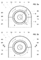
- Figure 2 shows the cross-section of a downward discharging exhaust hood 8 through the sidewall 11' and the diffuser outlet between the outer and inner flow guides. It shows a first portion 20 of the hood, in this case the upper portion, having an approximately semi-circular shape and the second portion 21 extending from the first portion downward toward the exhaust hood outlet 22.
- the exhaust hood outlet 22 leads into a condenser neck 23.
- the exhaust system of this type can also be arranged sideways, where the exhaust hood outlet is on either side of the turbine.
- the exhaust hood outlet can also be positioned at the top, above the level of the turbine.
- the transition or passage from the first to the second portion of the exhaust hood is referred as the throat of the exhaust hood.
- the throats or flow passages 24 and 25 from the first to the second portion of the exhaust hood are on either side of the turbine at the level of the turbine rotary axis 3.
- the throats are on either side of the turbine and either at, above or below the level of the turbine rotary axis.
- the working fluid experiences flow acceleration, which effects high-speed flow areas in an exhaust system of this type.
- the degree of re-acceleration of the working fluid flow is not the same in both throats on either side of the turbine.
- the re-acceleration is greater on one side depending on the direction of the tangential flow velocity vector S in the fluid flow, wherein most turbine designs the direction of the tangential flow velocity vector S corresponds to the direction of the turbine rotation R.
- the throat with the greater re-acceleration of fluid flow is, for most turbine designs, in the throat 25, which is positioned, in relation to the point A, in the direction of the tangential flow velocity vector S. Point A is farthest away from the exhaust hood outlet 22.
- the outer flow guide 12 has at its lip 13 a recess 14 that includes the angular position of throat or flow passage 25 and extends over a given angle away from the throat 25.
- the angular extent of the recess 14 includes the high-speed flow area within the exhaust hood.
- Figure 3a shows a first variant of the diffuser and exhaust system for a turbine having rotary axis 3 and rotating in the direction indicated by the arrow (clockwise direction).
- the exhaust hood has two throats 24 and 25 forming the passage for the working fluid between the outermost edge of the outer flow guide 12 and the sidewall of the exhaust hood at the transition point from the first portion 20 to the second portion 21 of the exhaust hood.
- throat 25 is the more critical throat with respect to the performance of the diffuser.
- the outer diffuser flow guide 12 is placed within the exhaust hood 8 and comprises, for example, several sections 12', which are arranged at a kink angle to each other.
- the section 12' at the end of the flow guide 12 has a lip 13 and is rotationally symmetric over a first angular segment C-B of the flow guide extending from point B in the clockwise direction to point C.
- the section 12' of the flow guide has a recess 14 extending from Point B in the clockwise direction to point C over an angular range ⁇ , which includes the angular position of flow passage or throat 25.
- the area of the recess 14 reaches for example about 45° in both rotational directions from the level of the throat 25.
- the depth of the recess 14 is, for example, equal to the depth of the outermost flow guide section 12'.
- the transition is realised by means of curved portions 30 and 31 extending over angles ⁇ 1 and ⁇ 2 .
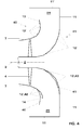
- Figure 3b shows another variation of the diffuser and exhaust system similar to that of figure 3a in all essential aspects of the invention.
- the recess area includes again the angular position of the throat 25.
- the recess 14 of the section 12' at the end of the flow guide extends from the position of the throat 25 in the clockwise direction over the angle ⁇ as far as the center of the exhaust hood outlet 22.
- This area includes all the high-speed flow area that may occur in exhaust systems of this type.
- the recess has curved transition portions 32 and 33.
- the profile of the outer flow guide 12 as well as of the inner flow guide 10 in figures 1-3 is identical over its entire circumference. In a further embodiment of the invention, the profile varies over the circumference as shown in connection with figure 4.
- Figure 4 shows a top view of a cross-section of the outer and inner flow guides 12 and 10 with flow guide sections 12' and 10', respectively.
- the profiles 40 and 41 of the outer and inner flow guides respectively lead to the diffuser outlet and throat 24.
- the profiles 42 and 43 of the outer and inner flow guides respectively lead to the diffuser outlet and to the throat 25.
- the outer flow guide profile 40 extends to the lip 13.
- the outer flow guide profile 42 leading to the throat 25 is shortened by the depth of the recess 14 in comparison to the outer flow guide profile 40 leading to the throat 24.
- the profile 42 differs from the profile 40 not only with regard to the recess 14, but also in the shape of the profile itself from the inlet at the last turbine blade row 4 of the diffuser up to the outlet of the diffuser.
- the profile 40 is shown in broken lines next to the profile 42.
- the profile 42 differs from the profile 40 in that its overall curvature of the profile 42 is smaller than that for profile 40. This measure avoids flow separation, which may occur otherwise due to the shorter profile of the outer flow guide.
- the inner flow guide 10 with sections 10' and profile 41 leads from the diffuser inlet to the endwall 11 of the exhaust hood and to the throat 24.
- the inner flow guide 10 with sections 10' and profile 43 leads from the diffuser inlet to the endwall 11 of the exhaust hood and to the throat 25.
- Profile 41 differs from profile 43, again in that the overall curvature of the profile 41 is greater than the curvature of profile 43.
- broken lines next to the profile 43 indicate the profile 41.
- the transition from profile 40 to profile 42 is realized by suitable geometrically smooth curves.
Landscapes
- Engineering & Computer Science (AREA)
- Mechanical Engineering (AREA)
- General Engineering & Computer Science (AREA)
- Supercharger (AREA)
- Turbine Rotor Nozzle Sealing (AREA)
- Structures Of Non-Positive Displacement Pumps (AREA)
Abstract
A diffuser and exhaust system (1) for a turbine comprises an axial-radial diffuser and an exhaust hood (8), where diffuser inner and outer flow guides (10, 12) extend from an inlet to an outlet, and the exhaust hood (8) comprises two throats or flow passages between the diffuser outlet and an exhaust hood side wall (11'). According to the invention, the outer flow guide (12) comprises a recess (14), at one of the said two flow passages. Said flow passage is positioned in relation to a point in the exhaust hood (8) in the direction of the tangential flow velocity vector, where said point in the exhaust hood (8) is farthest away from the exhaust hood outlet (22). The recess (14) prevents a re-acceleration of the flow within the exhaust hood (8) and effects an increase in the performance of the diffuser and exhaust hood system (1).
Description
- The invention pertains to an axial-radial diffuser and an exhaust system for a turbine, in particular a steam turbine.
- In a turbine with an axial-radial diffuser the working fluid is discharged following the last row of turbine blades and flows into an annularly flared flow passage, the diffuser, formed by an inner and an outer flow guide extending from the hub or tip of the last blade row of the turbine, respectively. The diffuser extends initially in the axial direction and circumferentially over the full 360° around the turbine rotary axis and then bends radially outwards with respect to the turbine rotary axis. The diffuser outlet typically leads to an exhaust hood, where typically the outlet is positioned within the exhaust hood. The exhaust hood in turn has an outlet to discharge the working fluid. In the case of a steam turbine, the outlet leads steam into a condenser. The exhaust hood has opposite its outlet a first portion with typically a semi-circular cross-section that encompasses half of the turbine and diffuser and a second portion with rectangular cross-section that extends from the first portion to the outlet of the exhaust hood. The transition from the first portion to the second portion of the exhaust hood is formed by two so-called throats, which are opposite from each other with respect to the turbine. The outlet is frequently arranged below the level of the turbine axis, which is frequently referred to as a downward discharging exhaust hood. However, it can also be arranged at the same level, or above the level of the turbine axis. A condenser would then be arranged adjacent on either side of the turbine or above the turbine, respectively.
The steam exiting a steam turbine after the last blade row diffuses, or decelerates, in the diffuser. As the kinetic energy of the steam flow is thus decreased in the diffuser, the static pressure rises correspondingly from the last row of turbine blades to the diffuser exit. With this increase of steam pressure in the flow direction in the diffuser there is a corresponding decrease in steam pressure at the level of the last turbine blade row as the pressure at the exhaust hood outlet is given by the cooling environment (for example the condenser) applied. Consequently, the turbine work output is increased compared to that of a turbine without a diffuser. Therefore, the pressure increase within the diffuser and the turbine power output can potentially be improved by an appropriate diffuser design. - Increasing the static pressure within the diffuser can optimize the performance of a turbine. However, losses can occur due to flow separation and vortex formations within the hood, which compromise the overall performance. Such vortices may develop to different degrees in different regions of a diffuser and exhaust hood, e.g. due to support struts or depending on the orientation of the exhaust hood. For example, in a diffuser, which leads the steam into a downward discharging exhaust hood (exhaust hood outlet below the level of the turbine), the steam diffusing in the lowest portion of the diffuser passage will enter the exhaust hood with no or very little change in flow direction. However, the steam diffusing in the uppermost portion of the diffuser and essentially being directed in the radial and vertically upward direction, experiences a change in flow direction of 180° in order to flow downwards into the exhaust hood and towards the outlet at the bottom. Such large changes in direction cause vortices and losses, which adversely affect the performance of the diffuser and consequently also the power output of the turbine.
-
US 5,518,366 discloses a diffuser for a turbo machine having an inner and outer flow guide each beginning at an inlet adjacent to the last blade row of the turbine and ending at an outlet within an exhaust hood. The downward discharging exhaust hood has a flow-guiding surface that has a distance from the inlet of the outer diffuser flow guide that varies over the circumference and has a minimum of less than the length of the last turbine blade at a particular location, for example at the top of the exhaust hood. The outer flow guide has an axial length from its inlet to its outlet that also varies over the circumference of the flow guide and has a minimum at the location where the minimum distance between the flow-guiding surface of the exhaust hood and the inlet of the outer flow guide occurs. The minimum distance between the flow-guiding surface of the exhaust hood and the inlet of the outer diffuser flow guide and the axial length of the outer flow guide are defined in relation to the length of the airfoil of the last turbine blade row. - It is an object of the invention to provide an axial-radial diffuser and exhaust system for a turbine that is improved in its aerodynamic performance, in particular in its static pressure recovery, over the diffusers of the state of the art.
- A diffuser and exhaust system comprises a diffuser and an exhaust hood, the diffuser having an inner and outer flow guide forming flow passage from an inlet at the last turbine blade row to an outlet positioned within the exhaust hood. The inner flow guide extends from the hub of the last turbine blade row to the diffuser outlet, while the outer flow guide extends from the turbine casing at the tip of the last blade row to the diffuser outlet. The diffuser is an axial-radial diffuser, which extends first in the axial direction with respect to the turbine rotary axis and then bends in the radially outward direction. The exhaust hood comprises a first portion having and en wall and a sidewall extending around approximately one half of the circumference of the diffuser outlet. It further comprises a second portion that extends from the first portion to a discharge outlet. The exhaust hood comprises two throats or flow passages between the diffuser outlet and the sidewall of the exhaust hood. They are positioned at the point of transition from the first portion to the second portion of the exhaust hood, at circumferentially opposite sides of the turbine.
- According to the invention, the outer flow guide comprises a lip at the diffuser outlet that is rotationally symmetric over a first segment of the circumference and comprises a recess or cutout over a second segment of the circumference. The extent of the second segment of the circumference includes the angular position of one of the two throats. The particular throat is positioned in the direction of the tangential flow velocity vector in relation to a particular point in the exhaust hood. This point in the exhaust hood is circumferentially opposite of the exhaust hood outlet and the point that is farthest away from the exhaust hood outlet.
- The tangential flow velocity component is the component of the absolute flow velocity vector leaving the last stage of the turbine. The direction of the tangential flow velocity vector depends on the design of the last turbine blade row. In many turbines, this direction coincides with the direction of the turbine rotation. In other turbine designs however, the direction of the tangential flow velocity vector is in the direction opposite the turbine rotation.
- For example, in a turbine there is a tangential flow velocity vector in the direction of the turbine rotation, where this direction is the clockwise direction. If the turbine is equipped with a downward discharging exhaust hood, the point circumferentially opposite the exhaust hood outlet is at the top of the hood. According to the invention, the recess at the outer diffuser flow guide is then positioned at the throat on the right hand side of the exhaust hood when viewing the exhaust hood from its inlet.
- The recess or cutout on the lip of the outer flow guide is placed at only one of the two throats or flow passages from the first portion to the second portion of the exhaust hood. About this particular throat, where the recess is acting, there is typically a high-speed flow area, at which the tangential flow velocity vector tends to push the working fluid predominantly. It is therefore the area that is most critical in terms of re-acceleration and static pressure decrease. The particular placement of the recess at this throat effects an enlargement and prevents a re-acceleration of the working fluid in the throat area. A rise in kinetic energy and decrease in static pressure is therefore prevented and the performance of the diffuser and exhaust system is improved.
- In a first exemplary embodiment of the invention, the angular range of the second segment of the outer flow guide circumference includes the position of said throat, where the angular range of the recess extends in both rotational directions an angular range up to 140°, i.e. towards as well away from the exhaust hood outlet. It includes therewith a high-speed flow area having vortices that extend in both directions from the throat. In a preferred exemplary embodiment of the invention, the angular extent of second segment lies in a range up to 90°.
- In a second exemplary embodiment of the invention, the angular range of the recess extends from the position of said throat in the direction of the tangential flow velocity vector, where the angular extent lies in a range up to 90°.
- In both first and second exemplary embodiments, the angular range of the recess at its greatest extent, reaches as far as the center of the outlet of the exhaust hood. Such range includes the largest extent of the high-speed flow area in the exhaust hood.
- In the first and second exemplary embodiments of the invention, the diffuser profile is the same over the entire circumference of the diffuser that is in both the first and second segments of the diffuser.
In a further exemplary embodiment of the invention, the meridional cross-sectional profile of the flow guide in the first portion of the circumference differs from the profile in the second portion of the circumference. The recess on the lip of a flow guide gives rise to a relatively abrupt transition, which can cause a diminished diffuser performance. In order to compensate for this loss of performance, the profile of the flow guide in the angular range of the recess, i.e. of the second segment of the circumference is altered compared to the profile over the rest of the circumference, i.e. in the first segment of the circumference. Between the two segments there is a smooth geometrical transition. This measure, in particular, avoids losses associated with flow separation and vortices.
In an exemplary embodiment, the profile in the first segment having a recess has an overall curvature that is smaller compared to the curvature of the profile in the second segment outside the recess area. -
- Figure 1 shows a view of an embodiment of the turbine diffuser and exhaust system according to the invention.
- Figure 2 shows a cross-section of the exhaust hood taken along the line II-II in figure 1.
- Figures 3a and b show a cross-section taken at lines III-III in figure 1 of the exhaust hood and diffuser outer flow guide according to the invention as viewed in the direction of working fluid flow. They each show an exemplary embodiment of the outer flow guide with different angular extents of the recess or cutout.
- Figure 4 shows a meridional cross-section taken at lines IV-IV in figure 3 of the outer flow guide of a particular embodiment of the diffuser according to the invention.
- Figure 1 shows an
exhaust system 1 for a turbine having aturbine rotor 2 withturbine rotary axis 3 rotating in a direction as indicated by the arrow. Of the turbine blades only the last blade row is shown, arranged on therotor 2 withblades 4 extending from thehub 5 to theblade tips 6. Aninner turbine casing 7 encloses the turbine channel up to the tips of the last blade row. The turbine exhaust system includes an axial-radial diffuser and anexhaust hood 8, where the diffuser provides a flow passage for theturbine working fluid 9 from the turbine last blade row into theexhaust hood 8. Theexhaust hood 8 is in this case a downward discharging exhaust hood having an outlet (not shown) below the level of the turbine. It comprises anendwall 11 and a sidewall 11' that extends around approximately one half of the diffuser outlet's circumference. The workingfluid 9 entering the exhaust hood flows toward the exhaust hood outlet, where at the topmost space within the hood the fluid abruptly changes its flow direction and in the lowermost space of the hood the fluid undergoes the least change in flow direction.
The diffuser comprises aninner flow guide 10 extending from thehub 5 first in the axial direction with respect to theturbine rotary axis 3, then bending radially outward and ending at theend wall 11 of theexhaust hood 8. A diffuserouter flow guide 12 extends from the end of theinner casing 7 first in the axial direction, bending in the radial outward direction and ending within theexhaust hood 8. The diffuser guides the workingfluid 9 into the exhaust hood, where it flows downward. In the example shown, the inner and outer flow guides 10 and 12 are configured of several straight edged individual flow passage sections 10' and 12', which are joined at kink angles to each other. Theouter flow guide 12 has alip 13 at its end, which according to the invention has a recess orcutout 14 over an angular range that reduces the length of the outer flow guide. In the embodiment shown, the recess has a depth equal to the straight edged section at the end of the outer flow guide. In a further embodiment, the depth includes more than one section.
In a further embodiment of the invention, the inner or outer flow guide or both glow guides are realized in one smoothly shaped piece (without kink angles in its profile). In this case, the depth of the recess is arbitrary. - Figure 2 shows the cross-section of a downward discharging
exhaust hood 8 through the sidewall 11' and the diffuser outlet between the outer and inner flow guides. It shows afirst portion 20 of the hood, in this case the upper portion, having an approximately semi-circular shape and thesecond portion 21 extending from the first portion downward toward theexhaust hood outlet 22. In the case of a steam turbine system, theexhaust hood outlet 22 leads into acondenser neck 23. The exhaust system of this type can also be arranged sideways, where the exhaust hood outlet is on either side of the turbine. The exhaust hood outlet can also be positioned at the top, above the level of the turbine. These types of exhaust systems are referred as sideways or upwards discharging systems. All geometric features of the diffuser and exhaust hood according to the invention as described herein are in sideways or upward exhaust systems rotated accordingly. The transition or passage from the first to the second portion of the exhaust hood is referred as the throat of the exhaust hood. In the exhaust hood shown, the throats or flowpassages turbine rotary axis 3. Depending on the design and placement of the first portion of the exhaust hood with respect to theturbine rotary axis 3, the throats are on either side of the turbine and either at, above or below the level of the turbine rotary axis. In thethroats throat 25, which is positioned, in relation to the point A, in the direction of the tangential flow velocity vector S. Point A is farthest away from theexhaust hood outlet 22. According to the invention, theouter flow guide 12 has at its lip 13 arecess 14 that includes the angular position of throat or flowpassage 25 and extends over a given angle away from thethroat 25. The angular extent of therecess 14 includes the high-speed flow area within the exhaust hood. - Figure 3a shows a first variant of the diffuser and exhaust system for a turbine having
rotary axis 3 and rotating in the direction indicated by the arrow (clockwise direction). The exhaust hood has twothroats outer flow guide 12 and the sidewall of the exhaust hood at the transition point from thefirst portion 20 to thesecond portion 21 of the exhaust hood. Typically,throat 25 is the more critical throat with respect to the performance of the diffuser. (In turbine designs with tangential flow velocity vectors in a direction opposite the turbine rotary direction, the critical throat would bethroat 24.) The outerdiffuser flow guide 12 is placed within theexhaust hood 8 and comprises, for example, several sections 12', which are arranged at a kink angle to each other. The section 12' at the end of theflow guide 12 has alip 13 and is rotationally symmetric over a first angular segment C-B of the flow guide extending from point B in the clockwise direction to point C. In a second angular segment B-C of the circumference, the section 12' of the flow guide has arecess 14 extending from Point B in the clockwise direction to point C over an angular range α, which includes the angular position of flow passage orthroat 25. The area of therecess 14 reaches for example about 45° in both rotational directions from the level of thethroat 25. The depth of therecess 14 is, for example, equal to the depth of the outermost flow guide section 12'. In order to prevent flow separation or vortices about the points of transition to therecess 14, the transition is realised by means ofcurved portions - Figure 3b shows another variation of the diffuser and exhaust system similar to that of figure 3a in all essential aspects of the invention. In this variant, the recess area includes again the angular position of the
throat 25. Therecess 14 of the section 12' at the end of the flow guide extends from the position of thethroat 25 in the clockwise direction over the angle α as far as the center of theexhaust hood outlet 22. This area includes all the high-speed flow area that may occur in exhaust systems of this type. Similar to the diffuser in figure 3a, the recess hascurved transition portions - The profile of the outer flow guide 12 as well as of the
inner flow guide 10 in figures 1-3 is identical over its entire circumference. In a further embodiment of the invention, the profile varies over the circumference as shown in connection with figure 4.
Figure 4 shows a top view of a cross-section of the outer and inner flow guides 12 and 10 with flow guide sections 12' and 10', respectively. Theprofiles throat 24. Theprofiles throat 25.
The outerflow guide profile 40 extends to thelip 13. The outerflow guide profile 42 leading to thethroat 25 is shortened by the depth of therecess 14 in comparison to the outerflow guide profile 40 leading to thethroat 24. In the particular embodiment shown in this figure, theprofile 42 differs from theprofile 40 not only with regard to therecess 14, but also in the shape of the profile itself from the inlet at the lastturbine blade row 4 of the diffuser up to the outlet of the diffuser. In order to illustrate the difference between the profiles, theprofile 40 is shown in broken lines next to theprofile 42. Theprofile 42 differs from theprofile 40 in that its overall curvature of theprofile 42 is smaller than that forprofile 40. This measure avoids flow separation, which may occur otherwise due to the shorter profile of the outer flow guide.
The inner flow guide 10 with sections 10' andprofile 41 leads from the diffuser inlet to theendwall 11 of the exhaust hood and to thethroat 24. The inner flow guide 10 with sections 10' andprofile 43 leads from the diffuser inlet to theendwall 11 of the exhaust hood and to thethroat 25.Profile 41 differs fromprofile 43, again in that the overall curvature of theprofile 41 is greater than the curvature ofprofile 43. In order to illustrate the difference, broken lines next to theprofile 43 indicate theprofile 41.
The transition fromprofile 40 toprofile 42 is realized by suitable geometrically smooth curves. -
- 1
- diffuser and exhaust system
- 2
- rotor
- 3
- turbine rotary axis
- 4
- turbine blades
- 5
- hub
- 6
- blade tips
- 7
- turbine casing
- 8
- exhaust hood
- 9
- working fluid flow direction
- 10
- inner flow guide
- 11
- end wall of the exhaust hood
- 11'
- sidewall of the exhaust hood
- 12
- outer flow guide
- 13
- lip of the outer flow guide
- 14
- recess or cutout from the
lip 13 of theouter flow guide 12 - 15-19
- ----
- 20
- first (upper) portion of exhaust hood
- 21
- second (lower) portion of the exhaust hood
- 22
- outlet of exhaust hood
- 23
- condenser neck
- 24
- throat
- 25
- throat
- 30-33
- curved transition portions to the
recess 14 - R
- direction of rotation of the turbine rotor
- S
- direction of tangential flow velocity vector (typical in the direction of turbine rotation; however can also be in direction oppositethe turbine rotation)
- A
- point farthest away from exhaust hood outlet
- B, C
- points delimiting angular extent of
recess 14 inouter flow guide 12 - α
- angle of
recess 14 - β1, β2
- angular extent of transition portion into
recess 14 - 40
- profile of outer flow guide leading to
throat 24 - 41
- profile of inner flow guide leading to
throat 24 - 42
- profile of outer flow guide leading to
throat 25 - 43
- profile of inner flow guide leading to
throat 25
Claims (11)
- Diffuser and exhaust system (1) for a turbine comprising an axial-radial diffuser and an exhaust hood (8), the diffuser comprising an inner flow guide (10) and an outer flow guide (12), each extending from a diffuser inlet at the last turbine blade row (4) to a diffuser outlet, the inner flow guide (10) extending from the hub (5) at the last turbine blade row (4) and the outer flow guide (12) extending from the turbine casing (7) at the last blade row (4), and the diffuser outlet extending from the end of the inner flow guide to the end of the outer flow guide (12), and the exhaust hood (8) comprising a first portion (20) comprising an endwall (11) and a sidewall (11') extending around approximately half the circumference of the diffuser outlet and a second portion (21) extending from the first portion (20) to an exhaust hood outlet (22), the exhaust hood (8) comprising two flow passages (24, 25) at the transition points from the first portion (20) to the second portion (21) of the exhaust hood (8) and between the diffuser outlet and the exhaust hood side wall (11'),
characterized by
the outer flow guide (12) comprising a lip (13) at the diffuser outlet that is rotationally symmetric over a first segment (C-B) of the outer flow guide circumference and comprising a recess (14) over a second segment (B-C, α) of the circumference, where the angular extent of the second segment (α) of the circumference includes the angular position of one of the said two flow passages (24, 25), where that flow passage (25) is positioned in relation to a point (A) in the exhaust hood (8) in the direction of the tangential flow velocity vector (S), where said point (A) in the exhaust hood (8) is farthest away from the exhaust hood outlet (22). - Diffuser and exhaust system (1) according to claim 1
characterized in that
said second segment (B-C, α) extends over an angular range (α) up to 140°. - Diffuser and exhaust system (1) according to claim 2
characterized in that
said second segment (B-C, α) extends over an angular range (α) up to 90°. - Diffuser and exhaust system (1) according to claim 3
characterized in that
said second segment (B-C, α) extends from said one flow passage (25) in the direction of the tangential flow velocity vector (S). - Diffuser and exhaust system (1) according to claim 2 or 3
characterized in that
said second segment (B-C, α) extends from said one flow passage (25) in both rotational directions. - Diffuser and exhaust system (1) according to any foregoing claim
characterized in that
the meridional cross-sectional profile of the outer flow guide (12) and the inner flow guide (10) is the same over their entire circumference. - Diffuser and exhaust system (1) according to any foregoing claim
characterized in that
the meridional cross-sectional profile (40) of the outer flow guide (12) in the first segment (C-B) of the circumference differs from the meridional cross-sectional profile (42) in the second segment (B-C) of the circumference of the outer flow guide (12). - Diffuser and exhaust system (1) according to claim 6
characterized in that
the meridional cross-sectional profile (41) of the inner flow guide (10) in the first segment of the circumference differs from the meridional cross-sectional profile (43) in the second segment of the circumference of the inner flow guide (10). - Diffuser and exhaust system (1) according to any foregoing claim
characterized in that
the tangential flow velocity vector (S) is in the direction of the turbine rotation (R). - Diffuser and exhaust system (1) according to any one of the foregoing claims
characterized in that
the tangential flow velocity vector (S) is in the direction oppositethe turbine rotation (R). - Diffuser and exhaust system (1) according to any one of the foregoing claims
characterized in that
the turbine is a steam turbine.
Priority Applications (6)
| Application Number | Priority Date | Filing Date | Title |
|---|---|---|---|
| EP06123940A EP1921278A1 (en) | 2006-11-13 | 2006-11-13 | Diffuser and exhaust system for turbine |
| DE112007002564T DE112007002564T5 (en) | 2006-11-13 | 2007-10-11 | Diffuser and exhaust system for turbine |
| PCT/EP2007/060821 WO2008058821A1 (en) | 2006-11-13 | 2007-10-11 | Diffuser and exhaust system for turbine |
| CN200780046044.6A CN101563526B (en) | 2006-11-13 | 2007-10-11 | Diffuser and exhaust system for turbine |
| JP2009535657A JP5230638B2 (en) | 2006-11-13 | 2007-10-11 | Turbine diffuser and exhaust system |
| US12/463,203 US7934904B2 (en) | 2006-11-13 | 2009-05-08 | Diffuser and exhaust system for turbine |
Applications Claiming Priority (1)
| Application Number | Priority Date | Filing Date | Title |
|---|---|---|---|
| EP06123940A EP1921278A1 (en) | 2006-11-13 | 2006-11-13 | Diffuser and exhaust system for turbine |
Publications (1)
| Publication Number | Publication Date |
|---|---|
| EP1921278A1 true EP1921278A1 (en) | 2008-05-14 |
Family
ID=37667143
Family Applications (1)
| Application Number | Title | Priority Date | Filing Date |
|---|---|---|---|
| EP06123940A Withdrawn EP1921278A1 (en) | 2006-11-13 | 2006-11-13 | Diffuser and exhaust system for turbine |
Country Status (6)
| Country | Link |
|---|---|
| US (1) | US7934904B2 (en) |
| EP (1) | EP1921278A1 (en) |
| JP (1) | JP5230638B2 (en) |
| CN (1) | CN101563526B (en) |
| DE (1) | DE112007002564T5 (en) |
| WO (1) | WO2008058821A1 (en) |
Cited By (7)
| Publication number | Priority date | Publication date | Assignee | Title |
|---|---|---|---|---|
| FR2924745A1 (en) * | 2007-11-13 | 2009-06-12 | Gen Electric | METHODS AND SYSTEMS FOR MOUNTING EXHAUST CASING FOR TURBINE |
| EP2677123A1 (en) * | 2012-06-18 | 2013-12-25 | Alstom Technology Ltd | Diffuser for turbomachines |
| JP2015055229A (en) * | 2013-09-13 | 2015-03-23 | ゼネラル・エレクトリック・カンパニイ | Exhaust system for use in turbine and assembly method thereof |
| EP2896793A1 (en) | 2014-01-21 | 2015-07-22 | Alstom Technology Ltd | Method of operating a gas turbine assembly and the gas turbine assembly |
| US9109467B2 (en) | 2012-07-05 | 2015-08-18 | General Electric Company | Exhaust system for use with a turbine and method of assembling same |
| EP3192983A1 (en) * | 2016-01-12 | 2017-07-19 | Mitsubishi Hitachi Power Systems, Ltd. | Exhaust hood and its flow guide for steam turbine |
| WO2024179628A1 (en) * | 2023-03-02 | 2024-09-06 | Bobcik Marek | Turbine deflector |
Families Citing this family (26)
| Publication number | Priority date | Publication date | Assignee | Title |
|---|---|---|---|---|
| US8317467B2 (en) * | 2009-12-29 | 2012-11-27 | General Electric Company | Radial channel diffuser for steam turbine exhaust hood |
| US8439633B2 (en) * | 2010-01-04 | 2013-05-14 | General Electric Company | Hollow steam guide diffuser having increased pressure recovery |
| US8398359B2 (en) * | 2010-02-17 | 2013-03-19 | General Electric Company | Exhaust diffuser |
| US20110236201A1 (en) * | 2010-03-23 | 2011-09-29 | Sumedhkumar Vyankatesh Shende | Method and apparatus for radial exhaust gas turbine |
| EP2441918A1 (en) | 2010-10-18 | 2012-04-18 | Siemens Aktiengesellschaft | Gas turbine annular diffuser |
| JP5951187B2 (en) * | 2011-03-29 | 2016-07-13 | 三菱重工業株式会社 | Turbine exhaust structure and gas turbine |
| US20130022444A1 (en) * | 2011-07-19 | 2013-01-24 | Sudhakar Neeli | Low pressure turbine exhaust diffuser with turbulators |
| US9057287B2 (en) | 2011-08-30 | 2015-06-16 | General Electric Company | Butterfly plate for a steam turbine exhaust hood |
| US9062568B2 (en) * | 2011-10-14 | 2015-06-23 | General Electric Company | Asymmetric butterfly plate for steam turbine exhaust hood |
| US8961116B2 (en) * | 2012-05-22 | 2015-02-24 | Braden Manufacturing, Llc | Exhaust plenum for gas turbine |
| US9644496B2 (en) * | 2013-03-13 | 2017-05-09 | General Electric Company | Radial diffuser exhaust system |
| US20140348647A1 (en) * | 2013-05-24 | 2014-11-27 | Solar Turbines Incorporated | Exhaust diffuser for a gas turbine engine exhaust system |
| WO2016001002A1 (en) * | 2014-07-03 | 2016-01-07 | Abb Turbo Systems Ag | Discharge region of a turbocharger turbine |
| FR3030633B1 (en) * | 2014-12-22 | 2019-04-12 | Airbus Helicopters | EXHAUST PIPE OF A TURBOMOTEUR WHOSE OUTLET IS PERPENDICULAR TO THE AXIS OF ROTATION OF THE TURBOMOTEUR |
| US10287920B2 (en) | 2015-11-24 | 2019-05-14 | General Electric Company | System of supporting turbine diffuser |
| US10036267B2 (en) | 2015-11-24 | 2018-07-31 | General Electric Company | System of supporting turbine diffuser outlet |
| US10041365B2 (en) | 2015-11-24 | 2018-08-07 | General Electric Company | System of supporting turbine diffuser |
| US10041377B2 (en) * | 2015-11-24 | 2018-08-07 | General Electric Company | System and method for turbine diffuser |
| US10036283B2 (en) | 2015-11-24 | 2018-07-31 | General Electric Company | System and method for diffuser AFT plate assembly |
| DE102017108368B4 (en) * | 2016-05-11 | 2025-02-13 | General Electric Technology Gmbh | System and method for a diffuser backplate assembly |
| JP2018087532A (en) * | 2016-11-29 | 2018-06-07 | 三菱重工業株式会社 | Steam turbine |
| JP6847673B2 (en) * | 2017-01-17 | 2021-03-24 | 株式会社東芝 | Turbine exhaust chamber |
| EP3354868A1 (en) * | 2017-01-30 | 2018-08-01 | General Electric Company | Asymmetric gas turbine exhaust diffuser |
| JP6944871B2 (en) * | 2017-12-28 | 2021-10-06 | 三菱パワー株式会社 | Exhaust chamber and steam turbine |
| US11486262B2 (en) * | 2021-03-03 | 2022-11-01 | General Electric Company | Diffuser bleed assembly |
| US12529325B1 (en) * | 2025-07-29 | 2026-01-20 | Pratt & Whitney Canada Corp. | Turbine exhaust duct with stiffeners for aircraft engines |
Citations (3)
| Publication number | Priority date | Publication date | Assignee | Title |
|---|---|---|---|---|
| US5518366A (en) * | 1994-06-13 | 1996-05-21 | Westinghouse Electric Corporation | Exhaust system for a turbomachine |
| US20020174655A1 (en) * | 2001-05-22 | 2002-11-28 | Tarelin Anatoly Oleksiovych | Device to increase turbine efficiency by removing electric charge from steam |
| JP2005233154A (en) * | 2004-02-23 | 2005-09-02 | Toshiba Corp | Steam turbine |
Family Cites Families (12)
| Publication number | Priority date | Publication date | Assignee | Title |
|---|---|---|---|---|
| US3149470A (en) * | 1962-08-29 | 1964-09-22 | Gen Electric | Low pressure turbine exhaust hood |
| JPS52168103U (en) * | 1977-06-16 | 1977-12-20 | ||
| JPS5672206A (en) * | 1979-11-14 | 1981-06-16 | Nissan Motor Co Ltd | Diffuser with collector |
| JPS6363541U (en) * | 1986-10-17 | 1988-04-26 | ||
| US5257906A (en) * | 1992-06-30 | 1993-11-02 | Westinghouse Electric Corp. | Exhaust system for a turbomachine |
| US5494405A (en) * | 1995-03-20 | 1996-02-27 | Westinghouse Electric Corporation | Method of modifying a steam turbine |
| JPH08260904A (en) * | 1995-03-29 | 1996-10-08 | Toshiba Corp | Steam turbine exhaust chamber |
| SE509521C2 (en) * | 1997-06-05 | 1999-02-08 | Abb Stal Ab | Outlet device for a flow machine |
| US6419448B1 (en) * | 2000-03-20 | 2002-07-16 | Jerzy A. Owczarek | Flow by-pass system for use in steam turbine exhaust hoods |
| JP2004150357A (en) * | 2002-10-30 | 2004-05-27 | Toshiba Corp | Steam turbine |
| JP4541813B2 (en) * | 2004-09-17 | 2010-09-08 | 株式会社日立製作所 | Steam turbine low pressure exhaust chamber |
| JP4619849B2 (en) * | 2005-03-31 | 2011-01-26 | 株式会社日立製作所 | Turbine exhaust system |
-
2006
- 2006-11-13 EP EP06123940A patent/EP1921278A1/en not_active Withdrawn
-
2007
- 2007-10-11 JP JP2009535657A patent/JP5230638B2/en not_active Expired - Fee Related
- 2007-10-11 DE DE112007002564T patent/DE112007002564T5/en not_active Ceased
- 2007-10-11 WO PCT/EP2007/060821 patent/WO2008058821A1/en not_active Ceased
- 2007-10-11 CN CN200780046044.6A patent/CN101563526B/en not_active Expired - Fee Related
-
2009
- 2009-05-08 US US12/463,203 patent/US7934904B2/en not_active Expired - Fee Related
Patent Citations (3)
| Publication number | Priority date | Publication date | Assignee | Title |
|---|---|---|---|---|
| US5518366A (en) * | 1994-06-13 | 1996-05-21 | Westinghouse Electric Corporation | Exhaust system for a turbomachine |
| US20020174655A1 (en) * | 2001-05-22 | 2002-11-28 | Tarelin Anatoly Oleksiovych | Device to increase turbine efficiency by removing electric charge from steam |
| JP2005233154A (en) * | 2004-02-23 | 2005-09-02 | Toshiba Corp | Steam turbine |
Cited By (9)
| Publication number | Priority date | Publication date | Assignee | Title |
|---|---|---|---|---|
| FR2924745A1 (en) * | 2007-11-13 | 2009-06-12 | Gen Electric | METHODS AND SYSTEMS FOR MOUNTING EXHAUST CASING FOR TURBINE |
| EP2677123A1 (en) * | 2012-06-18 | 2013-12-25 | Alstom Technology Ltd | Diffuser for turbomachines |
| US9109467B2 (en) | 2012-07-05 | 2015-08-18 | General Electric Company | Exhaust system for use with a turbine and method of assembling same |
| JP2015055229A (en) * | 2013-09-13 | 2015-03-23 | ゼネラル・エレクトリック・カンパニイ | Exhaust system for use in turbine and assembly method thereof |
| EP2896793A1 (en) | 2014-01-21 | 2015-07-22 | Alstom Technology Ltd | Method of operating a gas turbine assembly and the gas turbine assembly |
| US10151250B2 (en) | 2014-01-21 | 2018-12-11 | Ansaldo Energia Switzerland AG | Method of operating a gas turbine assembly and the gas turbine assembly |
| EP3192983A1 (en) * | 2016-01-12 | 2017-07-19 | Mitsubishi Hitachi Power Systems, Ltd. | Exhaust hood and its flow guide for steam turbine |
| US10378388B2 (en) | 2016-01-12 | 2019-08-13 | Mitsubishi Hitachi Power Systems, Ltd. | Exhaust hood and its flow guide for steam turbine |
| WO2024179628A1 (en) * | 2023-03-02 | 2024-09-06 | Bobcik Marek | Turbine deflector |
Also Published As
| Publication number | Publication date |
|---|---|
| WO2008058821A1 (en) | 2008-05-22 |
| US7934904B2 (en) | 2011-05-03 |
| CN101563526B (en) | 2012-12-19 |
| US20090263241A1 (en) | 2009-10-22 |
| DE112007002564T5 (en) | 2009-10-01 |
| CN101563526A (en) | 2009-10-21 |
| JP2010509534A (en) | 2010-03-25 |
| JP5230638B2 (en) | 2013-07-10 |
Similar Documents
| Publication | Publication Date | Title |
|---|---|---|
| US7934904B2 (en) | Diffuser and exhaust system for turbine | |
| EP0886070B1 (en) | Centrifugal compressor and diffuser for the centrifugal compressor | |
| US8167548B2 (en) | Steam turbine | |
| US20110116907A1 (en) | Axial turbine | |
| EP2410186B1 (en) | Impeller and rotary machine | |
| EP2988006B1 (en) | Flow vector control for high speed centrifugal pumps | |
| JP5029024B2 (en) | Centrifugal compressor | |
| EP2226471B1 (en) | Working fluid extraction in an axial turbine | |
| US10590773B2 (en) | Contouring a blade/vane cascade stage | |
| EP3421815B1 (en) | Centrifugal compressor | |
| JP2019157807A (en) | Centrifugal pump | |
| EP3998397B1 (en) | Steam turbine with diffuser | |
| JP2022129710A (en) | multistage centrifugal compressor | |
| JP3187468U (en) | Multistage centrifugal compressor | |
| US11927109B2 (en) | Gas turbine blade | |
| JPH0874603A (en) | Fluid extraction mechanism of compressor | |
| CN113906222B (en) | Stator vane for centrifugal compressor | |
| CN112746869B (en) | Controlled flow turbine blades | |
| JPS6380003A (en) | Exhaust diffuser cascade of axial-flow turbine | |
| KR101902693B1 (en) | Turbine apparatus |
Legal Events
| Date | Code | Title | Description |
|---|---|---|---|
| PUAI | Public reference made under article 153(3) epc to a published international application that has entered the european phase |
Free format text: ORIGINAL CODE: 0009012 |
|
| AK | Designated contracting states |
Kind code of ref document: A1 Designated state(s): AT BE BG CH CY CZ DE DK EE ES FI FR GB GR HU IE IS IT LI LT LU LV MC NL PL PT RO SE SI SK TR |
|
| AX | Request for extension of the european patent |
Extension state: AL BA HR MK RS |
|
| AKX | Designation fees paid | ||
| REG | Reference to a national code |
Ref country code: DE Ref legal event code: 8566 |
|
| STAA | Information on the status of an ep patent application or granted ep patent |
Free format text: STATUS: THE APPLICATION IS DEEMED TO BE WITHDRAWN |
|
| 18D | Application deemed to be withdrawn |
Effective date: 20081115 |