EP1921218A1 - A spacial structure and a method to build such a structure - Google Patents
A spacial structure and a method to build such a structure Download PDFInfo
- Publication number
- EP1921218A1 EP1921218A1 EP07075873A EP07075873A EP1921218A1 EP 1921218 A1 EP1921218 A1 EP 1921218A1 EP 07075873 A EP07075873 A EP 07075873A EP 07075873 A EP07075873 A EP 07075873A EP 1921218 A1 EP1921218 A1 EP 1921218A1
- Authority
- EP
- European Patent Office
- Prior art keywords
- reinforcing layer
- spatial structure
- structure according
- support body
- curable substance
- Prior art date
- Legal status (The legal status is an assumption and is not a legal conclusion. Google has not performed a legal analysis and makes no representation as to the accuracy of the status listed.)
- Withdrawn
Links
Images



Classifications
-
- E—FIXED CONSTRUCTIONS
- E04—BUILDING
- E04B—GENERAL BUILDING CONSTRUCTIONS; WALLS, e.g. PARTITIONS; ROOFS; FLOORS; CEILINGS; INSULATION OR OTHER PROTECTION OF BUILDINGS
- E04B1/00—Constructions in general; Structures which are not restricted either to walls, e.g. partitions, or floors or ceilings or roofs
- E04B1/16—Structures made from masses, e.g. of concrete, cast or similarly formed in situ with or without making use of additional elements, such as permanent forms, substructures to be coated with load-bearing material
- E04B1/167—Structures made from masses, e.g. of concrete, cast or similarly formed in situ with or without making use of additional elements, such as permanent forms, substructures to be coated with load-bearing material with permanent forms made of particular materials, e.g. layered products
- E04B1/168—Structures made from masses, e.g. of concrete, cast or similarly formed in situ with or without making use of additional elements, such as permanent forms, substructures to be coated with load-bearing material with permanent forms made of particular materials, e.g. layered products flexible
- E04B1/169—Structures made from masses, e.g. of concrete, cast or similarly formed in situ with or without making use of additional elements, such as permanent forms, substructures to be coated with load-bearing material with permanent forms made of particular materials, e.g. layered products flexible inflatable
-
- E—FIXED CONSTRUCTIONS
- E04—BUILDING
- E04G—SCAFFOLDING; FORMS; SHUTTERING; BUILDING IMPLEMENTS OR AIDS, OR THEIR USE; HANDLING BUILDING MATERIALS ON THE SITE; REPAIRING, BREAKING-UP OR OTHER WORK ON EXISTING BUILDINGS
- E04G11/00—Forms, shutterings, or falsework for making walls, floors, ceilings, or roofs
- E04G11/04—Forms, shutterings, or falsework for making walls, floors, ceilings, or roofs for structures of spherical, spheroid or similar shape, or for cupola structures of circular or polygonal horizontal or vertical section; Inflatable forms
-
- E—FIXED CONSTRUCTIONS
- E04—BUILDING
- E04G—SCAFFOLDING; FORMS; SHUTTERING; BUILDING IMPLEMENTS OR AIDS, OR THEIR USE; HANDLING BUILDING MATERIALS ON THE SITE; REPAIRING, BREAKING-UP OR OTHER WORK ON EXISTING BUILDINGS
- E04G11/00—Forms, shutterings, or falsework for making walls, floors, ceilings, or roofs
- E04G11/04—Forms, shutterings, or falsework for making walls, floors, ceilings, or roofs for structures of spherical, spheroid or similar shape, or for cupola structures of circular or polygonal horizontal or vertical section; Inflatable forms
- E04G11/045—Inflatable forms
Definitions
- the invention relates to a spatial structure built up of a support body to be placed on a support surface; a reinforcing layer to be arranged over the support body; and a curable substance to be poured over the reinforcing layer.
- the invention also relates to a method for constructing a spatial structure, comprising the steps of:
- Such a spatial structure is generally known. It is frequently used in the construction industry for constructing structures having a convex (synclastic) or a cylindrical shape. When a reinforcing layer (or reinforcing net) arranged over an inflatable construction is used, however, only shapes comprising a circle or a segment of a circle can be realised. Accordingly, only a limited number of shapes can be realised with the current, known structures, and consequently it is the object of the invention to provide a more versatile spatial structure which makes it possible to realise other shapes as well.
- the spatial structure is characterised in that the support body is made up of several support elements, and in that the reinforcing layer comprises a net structure, which has been pre-tensioned to a specific surface contour, with the inflatable support elements giving the reinforcing layer its shape.
- At least one support element is furthermore configured as a membrane that can be inflated with a medium.
- inflatable support elements or forms
- pre-tensioned reinforcing layer configured as a net structure arranged thereover makes it possible to realise various types of shapes.
- synclastic convex
- cylindrical shapes but also anticlastic or concave shapes.
- the spatial structure is characterised in that the pre-tensioned surface contour comprises at least the minimum surface area between one or several surface points and/or one or several surface lines.
- the reinforcing layer is given its shape by being tensioned.
- the shape of the net will in that case form the minimum surface area between a number of given elements.
- the shape of the mesh in tensioned condition is different from said minimum surface shape on account of
- Said pre-tensioned surface contour may furthermore be influenced in that according to the invention one or more lines of tension are created over the pre-tensioned surface contour.
- said at least one line of tension can create a deformation in the reinforcing layer towards or away from the inflatable form, so that this also makes it possible to design the spatial structure to comprise various concave or convex shapes.
- the reinforcing layer may be provided with one or more tensionable cables, which may or may not be incorporated in the reinforcing layer, whilst in another embodiment, with which various concave or convex shapes can be realised, the reinforcing layer is tensionably attached to the support surface.
- the curable substance is a grout, for example concrete, but the curable substance may also be a synthetic material, for example a polymer resin.
- the curable substance is ice.
- the invention also relates to a method for constructing a spatial structure, which method is according to the invention characterised by the further step of forming a surface contour counteracting the shape of the inflated support body in the reinforcing layer configured as a net structure prior to the execution of step iii).
- numeral 10 indicates a spatial structure according to a first embodiment, which is built up of a reinforcing layer 11 to be arranged over an inflatable form 12 that can be placed on a support surface 1.
- the inflatable support body 12 is made up of several, three in this embodiment, inflatable support elements 12a-12c.
- the inflatable support elements 12a-12c may have identical dimensions but also mutually different dimensions in order to thus realise random, irregular shapes of the spatial structure.
- the reinforcing layer 11, which is provided with a net structure is tensioned over the inflatable support body 12 and fastened down near the ends or edges 11a-11c. In this way it is possible to realise not only a convex (synclastic) shape at the location where the reinforcing layer 11 is arranged over the inflatable support elements 12a and 12c, but also a concave (anticlastic) shape, as is indicated at 11 b in figure 1.
- a self-supporting spatial structure By subsequently applying a curable substance, such as a grout, a polymer resin or ice, to the pre-tensioned net structure 11, a self-supporting spatial structure can be realised, after which the various inflatable support elements 12a-12c can be deflated and be removed from the spatial structure.
- a curable substance such as a grout, a polymer resin or ice
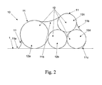
- FIG. 2 A different shape of a spatial structure is shown in figure 2, in which the inflatable support body 12 is made up of four inflatable support elements 12a-12d, so that a more complex spatial structure can be realised by fastening down the tensioned reinforcing layer 11 at the edges 11a-11c.
- the spatial structure comprises a number of convex (synclastic) portions as well as a few concave (anticlastic) portions 11 b.
- FIG. 1 A similar embodiment comprising four inflatable support elements 12a-12d is disclosed in figure 3.
- Figure 4 discloses yet another, more symmetric spatial structure made up of three inflatable support elements 12a-12c to obtain a convex shape alternated with a concave (anticlastic) shape 11 b-11 b'.
- figures 5 and 6 show embodiments in which the reinforcing layer in the form of a net structure is deformed in outward direction by a pillar 20 (figure 5) or a post 20 (figure 6).
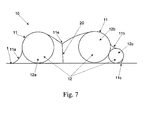
- the shape of the spatial structure of the illustrated embodiments is realised by the shapes of the support elements on the one hand and by fastening down the tensioned reinforcing layer at the edges 11 a-11 b on the other hand, it is also possible to influence the shapes by creating lines of tension in the reinforcing layer 11, for example by providing the reinforcing layer with cables 20, which are tensioned somehow or other, for example pulled upwards or downwards, as is shown in figure 7.
Landscapes
- Engineering & Computer Science (AREA)
- Architecture (AREA)
- Civil Engineering (AREA)
- Structural Engineering (AREA)
- Mechanical Engineering (AREA)
- Physics & Mathematics (AREA)
- Electromagnetism (AREA)
- Reinforcement Elements For Buildings (AREA)
- Rod-Shaped Construction Members (AREA)
Abstract
i) placing an inflatable support body on a support surface;
ii) arranging a reinforcing layer over the inflatable support body;
iii) inflating the inflatable support body with a medium under pressure;
iv) pouring a curable substance on top of the reinforcing layer.
Description
- The invention relates to a spatial structure built up of a support body to be placed on a support surface; a reinforcing layer to be arranged over the support body; and a curable substance to be poured over the reinforcing layer.
- The invention also relates to a method for constructing a spatial structure, comprising the steps of:
- i) placing an inflatable support body on a support surface;
- ii) arranging a reinforcing layer over the inflatable support body;
- iii) inflating the inflatable support body with a medium under pressure;
- iv) pouring a curable substance on top of the reinforcing layer.
- Such a spatial structure is generally known. It is frequently used in the construction industry for constructing structures having a convex (synclastic) or a cylindrical shape. When a reinforcing layer (or reinforcing net) arranged over an inflatable construction is used, however, only shapes comprising a circle or a segment of a circle can be realised. Accordingly, only a limited number of shapes can be realised with the current, known structures, and consequently it is the object of the invention to provide a more versatile spatial structure which makes it possible to realise other shapes as well.
- According to the invention, the spatial structure is characterised in that the support body is made up of several support elements, and in that the reinforcing layer comprises a net structure, which has been pre-tensioned to a specific surface contour, with the inflatable support elements giving the reinforcing layer its shape.
- In a functional embodiment, at least one support element is furthermore configured as a membrane that can be inflated with a medium.
- The combination of inflatable support elements (or forms) with a pre-tensioned reinforcing layer configured as a net structure arranged thereover makes it possible to realise various types of shapes. Thus it is possible to realise not only synclastic (convex) or cylindrical shapes, but also anticlastic or concave shapes.
- More specifically, the spatial structure is characterised in that the pre-tensioned surface contour comprises at least the minimum surface area between one or several surface points and/or one or several surface lines.
- More specifically, it is simpler to configure the reinforcing layer as a net having little flexural strength. In that case the mesh is given its shape by being tensioned. The shape of the net will in that case form the minimum surface area between a number of given elements. The shape of the mesh in tensioned condition is different from said minimum surface shape on account of
- the dimensions and the direction of the meshes of the net,
- the net's own weight,
- the creation, whether or not locally, of extra tension in the net,
- the shape of the mesh in the starting position thereof.
- Said pre-tensioned surface contour may furthermore be influenced in that according to the invention one or more lines of tension are created over the pre-tensioned surface contour. According to another embodiment, said at least one line of tension can create a deformation in the reinforcing layer towards or away from the inflatable form, so that this also makes it possible to design the spatial structure to comprise various concave or convex shapes.
- In a more functional embodiment, the reinforcing layer may be provided with one or more tensionable cables, which may or may not be incorporated in the reinforcing layer, whilst in another embodiment, with which various concave or convex shapes can be realised, the reinforcing layer is tensionably attached to the support surface.
- It is furthermore possible to effect a deformation in the opposite direction by the provision of a bar, a surface, a beam, an arch or a volume that presses the reinforcing layer outwards.
- In another functional embodiment, the curable substance is a grout, for example concrete, but the curable substance may also be a synthetic material, for example a polymer resin.
- In another functional embodiment, the curable substance is ice.
- The invention also relates to a method for constructing a spatial structure, which method is according to the invention characterised by the further step of forming a surface contour counteracting the shape of the inflated support body in the reinforcing layer configured as a net structure prior to the execution of step iii).
- The invention will now be explained in more detail with reference to the drawing, in which:
- Figures 1-7 schematically show a few embodiments of a spatial structure according to the invention. For a better understanding of the invention, like parts will be indicated by identical numerals in the description of the figures below.
- In figure 1,
numeral 10 indicates a spatial structure according to a first embodiment, which is built up of a reinforcinglayer 11 to be arranged over aninflatable form 12 that can be placed on asupport surface 1. - According to the invention, the
inflatable support body 12 is made up of several, three in this embodiment,inflatable support elements 12a-12c. Theinflatable support elements 12a-12c may have identical dimensions but also mutually different dimensions in order to thus realise random, irregular shapes of the spatial structure. According to the invention, the reinforcinglayer 11, which is provided with a net structure, is tensioned over theinflatable support body 12 and fastened down near the ends oredges 11a-11c. In this way it is possible to realise not only a convex (synclastic) shape at the location where the reinforcinglayer 11 is arranged over theinflatable support elements - By subsequently applying a curable substance, such as a grout, a polymer resin or ice, to the
pre-tensioned net structure 11, a self-supporting spatial structure can be realised, after which the variousinflatable support elements 12a-12c can be deflated and be removed from the spatial structure. - A different shape of a spatial structure is shown in figure 2, in which the
inflatable support body 12 is made up of fourinflatable support elements 12a-12d, so that a more complex spatial structure can be realised by fastening down the tensioned reinforcinglayer 11 at theedges 11a-11c. Also in this embodiment the spatial structure comprises a number of convex (synclastic) portions as well as a few concave (anticlastic)portions 11 b. - A similar embodiment comprising four
inflatable support elements 12a-12d is disclosed in figure 3. - Figure 4 discloses yet another, more symmetric spatial structure made up of three
inflatable support elements 12a-12c to obtain a convex shape alternated with a concave (anticlastic)shape 11 b-11 b'. - It will be understood that the construction according to the invention makes it possible to realise more functional and more complex spatial structures.
- Thus, figures 5 and 6 show embodiments in which the reinforcing layer in the form of a net structure is deformed in outward direction by a pillar 20 (figure 5) or a post 20 (figure 6).
- Although the shape of the spatial structure of the illustrated embodiments is realised by the shapes of the support elements on the one hand and by fastening down the tensioned reinforcing layer at the
edges 11 a-11 b on the other hand, it is also possible to influence the shapes by creating lines of tension in the reinforcinglayer 11, for example by providing the reinforcing layer withcables 20, which are tensioned somehow or other, for example pulled upwards or downwards, as is shown in figure 7.
Claims (12)
- A spatial structure built up of:a support body to be placed on a support surface;a reinforcing layer to be arranged over the support body; anda curable substance to be poured over the reinforcing layer,characterised in that the support body is made up of several support elements, and in that the reinforcing layer comprises a net structure, which has been pre-tensioned to a specific surface contour, with the inflatable support elements giving the reinforcing layer its shape.
- A spatial structure according to claim 1, characterised in that at least one support element is furthermore configured as a membrane that can be inflated with a medium.
- A spatial structure according to claim 1 or 2, characterised in that the pre-tensioned surface contour comprises at least the minimum surface area between one or several surface points and/or one or several surface lines.
- A spatial structure according to any one or more of the preceding claims, characterised in that the pre-tensioned surface contour of the reinforcing layer is different from the surface contour of said minimum surface area as a result of its own weight, an uneven distribution of the tensions in the reinforcing layer or of external forces exerted on the reinforcing layer and the dimensions and the direction of the meshes of the net and the form of the net.
- A spatial structure according to any one or more of the preceding claims, characterised in that there are one or more lines of tension in the pre-tensioned surface contour.
- A spatial structure according to claim 5, characterised in that said at least one line of tension creates a deformation in the reinforcing layer towards or away from the support elements.
- A spatial structure according to claim 5, characterised in that the reinforcing layer is provided with one or more tensionable cables incorporated in the reinforcing layer.
- A spatial structure according to any one or more of the preceding claims, characterised in that the reinforcing layer is tensionably attached to the support surface.
- A spatial structure according to any one or more of the claims 1-8, characterised in that the curable substance is a grout, for example concrete.
- A spatial structure according to any one or more of the claims 1-8, characterised in that the curable substance is a synthetic material, for example a polymer resin.
- A spatial structure according to any one or more of the claims 1-8, characterised in that the curable substance is ice.
- A method for constructing a spatial structure, comprising the steps of:i) placing an inflatable support body on a support surface;ii) arranging a reinforcing layer over the inflatable support body;iii) inflating the inflatable support body with a medium under pressure;iv) pouring a curable substance on top of the reinforcing layer, andv) forming a surface contour counteracting the shape of the inflated support body in the reinforcing layer configured as a net structure prior to the execution of step iii).
Applications Claiming Priority (1)
| Application Number | Priority Date | Filing Date | Title |
|---|---|---|---|
| NL1032665A NL1032665C2 (en) | 2006-10-11 | 2006-10-11 | Spatial building construction as well as a method for manufacturing such a spatial building construction. |
Publications (1)
| Publication Number | Publication Date |
|---|---|
| EP1921218A1 true EP1921218A1 (en) | 2008-05-14 |
Family
ID=37973614
Family Applications (1)
| Application Number | Title | Priority Date | Filing Date |
|---|---|---|---|
| EP07075873A Withdrawn EP1921218A1 (en) | 2006-10-11 | 2007-10-10 | A spacial structure and a method to build such a structure |
Country Status (2)
| Country | Link |
|---|---|
| EP (1) | EP1921218A1 (en) |
| NL (1) | NL1032665C2 (en) |
Citations (4)
| Publication number | Priority date | Publication date | Assignee | Title |
|---|---|---|---|---|
| US3506746A (en) * | 1966-12-20 | 1970-04-14 | Jean Louis Fontaine | Structural form and method for making architectural structures |
| US4094109A (en) * | 1977-02-22 | 1978-06-13 | Francois Prouvost | Construction of houses or similar buildings by means of an inflatable structure |
| GB2075082A (en) * | 1980-04-29 | 1981-11-11 | British Petroleum Co | Method of fabricating structures |
| US4746471A (en) * | 1984-11-14 | 1988-05-24 | Hale Loren E | Method of constructing a reinforced concrete structure |
-
2006
- 2006-10-11 NL NL1032665A patent/NL1032665C2/en not_active IP Right Cessation
-
2007
- 2007-10-10 EP EP07075873A patent/EP1921218A1/en not_active Withdrawn
Patent Citations (4)
| Publication number | Priority date | Publication date | Assignee | Title |
|---|---|---|---|---|
| US3506746A (en) * | 1966-12-20 | 1970-04-14 | Jean Louis Fontaine | Structural form and method for making architectural structures |
| US4094109A (en) * | 1977-02-22 | 1978-06-13 | Francois Prouvost | Construction of houses or similar buildings by means of an inflatable structure |
| GB2075082A (en) * | 1980-04-29 | 1981-11-11 | British Petroleum Co | Method of fabricating structures |
| US4746471A (en) * | 1984-11-14 | 1988-05-24 | Hale Loren E | Method of constructing a reinforced concrete structure |
Also Published As
| Publication number | Publication date |
|---|---|
| NL1032665C2 (en) | 2008-04-14 |
Similar Documents
| Publication | Publication Date | Title |
|---|---|---|
| CN1926292B (en) | Method and auxiliary device for producing concrete elements, in particular semi-finished concrete products and/or concrete slabs, and auxiliary device for producing concrete slabs | |
| CN112482857B (en) | Silo, silo top construction method thereof and air bag type formwork system of silo top | |
| US3506746A (en) | Structural form and method for making architectural structures | |
| CN102251620A (en) | Inflatable mould component for concrete filling | |
| US20040134141A1 (en) | Flexible tensioned structure and method of calculating such a structure | |
| EP2800844B1 (en) | Concrete flooring | |
| CN110983984B (en) | Construction method of main tower of golden flower tea type structure | |
| EP0357151B2 (en) | Method for manufacturing a building structure | |
| KR20130142129A (en) | Reinforcement element for casting comprising ring shaped portions and reinforcement with such reinforcement elements | |
| CN112681289B (en) | A kind of arch plate of pile plate wall and its production method | |
| EP2800657B1 (en) | Master model structure | |
| KR101859398B1 (en) | Building construction method using exposed concrete wall | |
| US3996320A (en) | Method for making domed skeletal structures of concrete | |
| HUP0600204A2 (en) | Method and shuttering for making or repairing columns | |
| EP1953301A2 (en) | Method for reinforcing a steel beam and steel beam obtained via this method | |
| JP3654879B2 (en) | Hollow material unit, precast concrete board and concrete slab | |
| NL1029368C2 (en) | Method for manufacturing a building construction from curable material, building construction and collection of parts therefor. | |
| JPS63284332A (en) | Construction method of dome and bag body for mold frame thereof | |
| JP2010285848A (en) | Composite columnar structure | |
| NL1032665C2 (en) | Spatial building construction as well as a method for manufacturing such a spatial building construction. | |
| CN104626341A (en) | Hollow slab internal mold and assembly and disassembly method thereof | |
| JPH07186131A (en) | Method for manufacturing precast concrete column with hollow structure and hollow form used for it | |
| ES2660055B2 (en) | INFLATABLE FORMWORK-REINFORCED SYSTEM FOR THE EXECUTION OF CONCRETE ELEMENTS AND PROCEDURE FOR THE EXECUTION OF A CONCRETE ELEMENT | |
| CN113107197B (en) | Double waistline casting formwork system and erection method for high-rise building facade decoration | |
| JP4530350B2 (en) | Concrete slab |
Legal Events
| Date | Code | Title | Description |
|---|---|---|---|
| PUAI | Public reference made under article 153(3) epc to a published international application that has entered the european phase |
Free format text: ORIGINAL CODE: 0009012 |
|
| AK | Designated contracting states |
Kind code of ref document: A1 Designated state(s): AT BE BG CH CY CZ DE DK EE ES FI FR GB GR HU IE IS IT LI LT LU LV MC MT NL PL PT RO SE SI SK TR |
|
| AX | Request for extension of the european patent |
Extension state: AL BA HR MK RS |
|
| 17P | Request for examination filed |
Effective date: 20081014 |
|
| AKX | Designation fees paid |
Designated state(s): AT BE BG CH CY CZ DE DK EE ES FI FR GB GR HU IE IS IT LI LT LU LV MC MT NL PL PT RO SE SI SK TR |
|
| 17Q | First examination report despatched |
Effective date: 20090105 |
|
| STAA | Information on the status of an ep patent application or granted ep patent |
Free format text: STATUS: THE APPLICATION IS DEEMED TO BE WITHDRAWN |
|
| 18D | Application deemed to be withdrawn |
Effective date: 20090716 |