EP1920885A1 - Method of improving nanotopography of surface of wafer and wire saw apparatus - Google Patents
Method of improving nanotopography of surface of wafer and wire saw apparatus Download PDFInfo
- Publication number
- EP1920885A1 EP1920885A1 EP06782522A EP06782522A EP1920885A1 EP 1920885 A1 EP1920885 A1 EP 1920885A1 EP 06782522 A EP06782522 A EP 06782522A EP 06782522 A EP06782522 A EP 06782522A EP 1920885 A1 EP1920885 A1 EP 1920885A1
- Authority
- EP
- European Patent Office
- Prior art keywords
- wire
- feed table
- saw apparatus
- work feed
- wire saw
- Prior art date
- Legal status (The legal status is an assumption and is not a legal conclusion. Google has not performed a legal analysis and makes no representation as to the accuracy of the status listed.)
- Granted
Links
Images


Classifications
-
- B—PERFORMING OPERATIONS; TRANSPORTING
- B24—GRINDING; POLISHING
- B24B—MACHINES, DEVICES, OR PROCESSES FOR GRINDING OR POLISHING; DRESSING OR CONDITIONING OF ABRADING SURFACES; FEEDING OF GRINDING, POLISHING, OR LAPPING AGENTS
- B24B27/00—Other grinding machines or devices
- B24B27/06—Grinders for cutting-off
-
- B—PERFORMING OPERATIONS; TRANSPORTING
- B28—WORKING CEMENT, CLAY, OR STONE
- B28D—WORKING STONE OR STONE-LIKE MATERIALS
- B28D5/00—Fine working of gems, jewels, crystals, e.g. of semiconductor material; apparatus or devices therefor
- B28D5/04—Fine working of gems, jewels, crystals, e.g. of semiconductor material; apparatus or devices therefor by tools other than rotary type, e.g. reciprocating tools
- B28D5/045—Fine working of gems, jewels, crystals, e.g. of semiconductor material; apparatus or devices therefor by tools other than rotary type, e.g. reciprocating tools by cutting with wires or closed-loop blades
-
- B—PERFORMING OPERATIONS; TRANSPORTING
- B23—MACHINE TOOLS; METAL-WORKING NOT OTHERWISE PROVIDED FOR
- B23D—PLANING; SLOTTING; SHEARING; BROACHING; SAWING; FILING; SCRAPING; LIKE OPERATIONS FOR WORKING METAL BY REMOVING MATERIAL, NOT OTHERWISE PROVIDED FOR
- B23D57/00—Sawing machines or sawing devices not covered by one of the preceding groups B23D45/00 - B23D55/00
- B23D57/003—Sawing machines or sawing devices working with saw wires, characterised only by constructional features of particular parts
- B23D57/0046—Sawing machines or sawing devices working with saw wires, characterised only by constructional features of particular parts of devices for feeding, conveying or clamping work
-
- B—PERFORMING OPERATIONS; TRANSPORTING
- B24—GRINDING; POLISHING
- B24B—MACHINES, DEVICES, OR PROCESSES FOR GRINDING OR POLISHING; DRESSING OR CONDITIONING OF ABRADING SURFACES; FEEDING OF GRINDING, POLISHING, OR LAPPING AGENTS
- B24B27/00—Other grinding machines or devices
- B24B27/06—Grinders for cutting-off
- B24B27/0633—Grinders for cutting-off using a cutting wire
-
- B—PERFORMING OPERATIONS; TRANSPORTING
- B24—GRINDING; POLISHING
- B24B—MACHINES, DEVICES, OR PROCESSES FOR GRINDING OR POLISHING; DRESSING OR CONDITIONING OF ABRADING SURFACES; FEEDING OF GRINDING, POLISHING, OR LAPPING AGENTS
- B24B47/00—Drives or gearings; Equipment therefor
- B24B47/02—Drives or gearings; Equipment therefor for performing a reciprocating movement of carriages or work- tables
- B24B47/04—Drives or gearings; Equipment therefor for performing a reciprocating movement of carriages or work- tables by mechanical gearing only
-
- B—PERFORMING OPERATIONS; TRANSPORTING
- B28—WORKING CEMENT, CLAY, OR STONE
- B28D—WORKING STONE OR STONE-LIKE MATERIALS
- B28D5/00—Fine working of gems, jewels, crystals, e.g. of semiconductor material; apparatus or devices therefor
- B28D5/0058—Accessories specially adapted for use with machines for fine working of gems, jewels, crystals, e.g. of semiconductor material
- B28D5/0082—Accessories specially adapted for use with machines for fine working of gems, jewels, crystals, e.g. of semiconductor material for supporting, holding, feeding, conveying or discharging work
-
- B—PERFORMING OPERATIONS; TRANSPORTING
- B28—WORKING CEMENT, CLAY, OR STONE
- B28D—WORKING STONE OR STONE-LIKE MATERIALS
- B28D5/00—Fine working of gems, jewels, crystals, e.g. of semiconductor material; apparatus or devices therefor
- B28D5/04—Fine working of gems, jewels, crystals, e.g. of semiconductor material; apparatus or devices therefor by tools other than rotary type, e.g. reciprocating tools
-
- B—PERFORMING OPERATIONS; TRANSPORTING
- B82—NANOTECHNOLOGY
- B82Y—SPECIFIC USES OR APPLICATIONS OF NANOSTRUCTURES; MEASUREMENT OR ANALYSIS OF NANOSTRUCTURES; MANUFACTURE OR TREATMENT OF NANOSTRUCTURES
- B82Y10/00—Nanotechnology for information processing, storage or transmission, e.g. quantum computing or single electron logic
Definitions
- the present invention relates to a method of improving nanotopography of a surface of a wafer, e.g., a silicon wafer or a compound semiconductor wafer sliced from an ingot by using a wire saw apparatus, and to a wire saw apparatus.
- a wafer e.g., a silicon wafer or a compound semiconductor wafer sliced from an ingot by using a wire saw apparatus, and to a wire saw apparatus.
- a single-crystal silicon ingot is sliced by using a wire saw apparatus (see, e.g., Japanese Patent Application Laid-open No. 85053-1996 ).
- the wire saw apparatus is an apparatus which enables a wire (a high-tension steel wire) to travel at a high speed and presses an ingot against the wire to be sliced (cut) while applying a slurry having GC (silicon carbide) abrasive grains dispersed in a liquid to the wire.
- GC silicon carbide
- an apparatus for slicing an ingot one which applies a tension of 2.5 to 3.0 kgf to a wire having a diameter of 0.14 mm to 0.18 mm and performs slicing while enabling the wire to travel in a reciprocating direction at an average speed of 400 to 500 m/min in a cycle of 1 to 2 c/min (30 to 60 s/c) is general in a conventional technology.
- the wire is unreeled from one wire reel and enters groove rollers through a tension giving mechanism constituted of one or both of a dancer roller including a dead weight or a powder clutch having a constant torque motor connected thereto.
- the groove roller is a roller having a structure where a polyurethane resin is pressed in a peripheral part of a cast steel cylinder and grooves are formed on a surface thereof at a fixed pitch, and the wire is wound around such rollers for 300 to 400 turns and then taken up by the other wire reel through the other tension giving mechanism.
- the wire is driven in the reciprocating direction in a predetermined cycle by a groove roller driving motor.
- the ingot is pressed against the wire at a preprogrammed ingot feed speed and sliced.
- FIG. 2 is a schematic view for explaining a mechanism for feeding an ingot in a conventional wire saw apparatus.
- this wire saw apparatus 10' an ingot 2' is held to a work feed table 3' guided by an LM guide (a linear-motion guide) 4' and sliced by using a wire row 1' wound around groove rollers 5'.
- the LM guide 4' is generally constituted of a "track rail” and a “slide unit including a steel ball or a cylindrical runner", and the slide unit linearly and smoothly moves on the track rail when the steel ball or the cylindrical runner which is in contact with the track rail rotates.
- nanotopography a size of a surface waviness component called a "nanotopography” is a problem in wafers in recent years.
- STI Shallow Trench Isolation
- the nanotopography is formed at processing steps (slicing to polishing) of a wafer, it has been revealed that the nanotopography due to slicing using a wire saw (i.e., slice waviness) can be classified into three types, i.e., "one which suddenly occurs", “one which occurs at start or end of slicing", and "one having periodicity".
- the nano-topographies it can be considered that the “one which extemporaneously occurs” is caused due to wire disconnection or an error in tension control of the wire saw apparatus, whilst the "one which occurs at start or end of slicing” is caused due to a sudden change in a cut-resistance, often resulting in rejection in nanotopography numerical value judgment.
- the "waviness having periodicity” often results in rejection in nanotopography sensory test, but its cause is unknown.
- a method of improving nanotopography of a surface of a wafer sliced from an ingot by using a wire saw apparatus at least including improving straightness of feed of a work feed table which is included in the wire saw apparatus and used for feeding the ingot to a wire row formed by winding a wire around a plurality of rollers.
- the straightness is defined as a distance Y from an ideal straight line of a trajectory when a material body moves by a distance X, and it is represented as Y/X.
- straightness of feed of the work feed table is improved by improving deformation of a linear-motion guide for linearly guiding the work feed table.
- the straightness of feed of the work feed table can be assuredly improved by improving deformation of the linear-motion guide for linearly guiding the work feed table in this manner.
- deformation of the linear-motion guide is improved by adjusting an interval between attachment holes and tightening torque of bolts, and the holes are used to attach the linear-motion guide to the wire saw apparatus by using the bolts. Since deformation of the linear-motion guide can be more assuredly improved by adjusting an interval between the attachment holes and tightening torque of bolts, and the holes are used to attach the linear-motion guide to the wire saw apparatus by using the bolts as explained above, the straightness of feed of the work feed table can be effectively improved.
- a wire saw apparatus for slicing an ingot to manufacture a wafer, including at least: a wire row formed by winding a wire around a plurality of rollers; a work feed table for holding and feeding the ingot to the wire row; and a linear-motion guide for linearly guiding the work feed table, wherein a component having a wavelength of 20 to 200 mm in straightness of feed of the work feed table satisfies a PV value ⁇ 1.0 ⁇ m.
- the wire saw apparatus which can eliminate slice waviness having periodicity and manufacture a wafer having an improved surface nanotopography can be provided as long as it includes: the wire row; the work feed table for holding the ingot to be fed to the wire row; and the linear-motion guide for linearly guiding the work feed table and the component having the wavelength of 20 to 200 mm in the straightness of feed of the work feed table satisfies the PV value ⁇ 1.0 ⁇ m.
- the wire saw apparatus can be a wire saw apparatus which can eliminate slice waviness having periodicity and manufacture a wafer having an improved surface nanotopography.
- the present inventors conducted the following experiment to find out this cause when achieving the present invention. That is, the straightness of feed of the work feed table in a wire saw apparatus was measured by using a straight edge and an electric micrometer. Specifically, the straight edge was attached to the work feed table, and a dislocation from a straight line was measured by the electric micrometer while feeding the work feed table approximately 300 mm by an LM guide (a linear-motion guide).
- FIG. 3 shows its result.
- a line (a) in FIG. 3 represents straightness of feed of the work feed table before performing a later-explained improvement.
- a line (b) in FIG. 3 represents straightness of feed of the work feed table having improved roundness of a cylindrical runner used for the LM guide.
- the waviness component having the wavelength of 14 mm corresponding to the pitch of the cylindrical runner is reduced to 1/3 or below of that before the improvement.
- the entire straightness becomes 1.48 ⁇ m/300 mm, and the improvement can be observed.
- a value 1.48 ⁇ m as the PV value was insufficient for an improving effect.
- the present inventors discovered from this result a possibility of being able to reduce further the "slice waviness having periodicity" by improving the long-period component of straightness of feed of the work feed table.
- short-period waviness having a wavelength of 14 mm has a small influence on the nanotopography of the polished wafer.
- the present inventors conceived that improving straightness (especially long-period waviness having a wavelength which exceeds 14 mm and is such as 20 to 200 mm) of the work feed table enables improving the nanotopography of a wafer surface, thereby bringing the present invention to completion.
- FIG. 1 is a schematic view showing an example of a wire saw apparatus according to the present invention.
- this wire saw apparatus 10 includes at least a wire row 1 formed by winding a wire saw around groove rollers 5, a work feed table 3 for holding and feeding an ingot 2 to the wire row 1, and an LM guide 4 for linearly guiding the work feed table 3, and a component having a wavelength of 20 to 200 mm as a long-period component in straightness of feed of the work feed table 3 satisfies a PV value ⁇ 1.0 ⁇ m.
- the wire saw apparatus 10 has such a structure to enable manufacturing a wafer having an improved nanotopography of a surface thereof.
- straightness of short-period waviness having a short wavelength e.g., the wavelength of 14 mm can be improved by improving roundness of a cylindrical runner, an improving effect is small in nanotopography of a polished wafer.
- long-period waviness having a long wavelength exceeding a diameter of a wafer e.g., 200 to 300 mm has a small influence in the polished wafer, a component with a wavelength of 20 to 200 mm satisfying the PV value ⁇ 1.0 ⁇ m can suffice.
- the smaller PV value is preferable.
- Such a wire saw apparatus according to the present invention can be realized by improving straightness of feed of the work feed table in a conventional wire saw apparatus by, e.g., using a later-explained method according to the present invention.
- improving straightness of feed of the work feed table used for feeding the ingot to the wire row enables improving the nanotopography of the wafer surface.
- Such an improvement in straightness of feed of the work feed table can be carried out by, e.g., improving straightness of the work feed table or the LM guide itself, improving an attachment precision of the LM guide with respect to the wire saw apparatus, improving deformation of the LM guide, or improving roundness of the cylindrical runner.
- specific precision improvement methods there are methods of:
- a wire saw apparatus 20 including a work feed table 13 which is used for feeding an ingot 12 to a wire row 11 formed by winding a wire around groove rollers 15 as shown in FIG. 5 (a) , intervals 17 between attachment holes 16 and tightening torque of bolts (not shown) in an LM guide 14 were changed to simulate its effect based on a finite element method. Then, it was confirmed in the simulation that deformation of the LM guide 14 was improved as shown in FIGS.
- straightness of feed of the work feed table can be assuredly improved by improving deformation of the linear-motion guide for linearly guiding the work feed table and, in particular, this deformation of the linear-motion guide can be more assuredly improved by adjusting intervals of the attachment holes which are used to attach the linear-motion guide to the wire saw apparatus by using bolts and tightening torque of the bolts.
- intervals of attachment holes which are used to attach an LM guide to the wire saw apparatus by using the bolts and tightening torque of bolts were respectively adjusted from 100 mm and 60 Nm (Comparative Example 1) to 75 mm and 40 Nm (Example 1) like the above-explained simulation. Further, straightness of feed of the work feed table was measured by the same method as above.
- Example 2 shows N numbers of the wafers and frequencies of occurrence of "slice waviness having periodicity" as a problem with a frequency of occurrence in Comparative Example 2 being determined as 100%.
- the frequency of occurrence of "slice waviness having periodicity” in Example 2 was improved to approximately 1/10 of that in Comparative Example 2 by improving straightness of feed of the work feed table carried out in Example 1.
- the present invention is not restricted thereto, and any method can be adopted as long as straightness of feed of the work feed table can be improved.
- the method of improving straightness of feed of the work feed table is not restricted in particular.
Landscapes
- Engineering & Computer Science (AREA)
- Mechanical Engineering (AREA)
- Mechanical Treatment Of Semiconductor (AREA)
- Finish Polishing, Edge Sharpening, And Grinding By Specific Grinding Devices (AREA)
- Processing Of Stones Or Stones Resemblance Materials (AREA)
- Constituent Portions Of Griding Lathes, Driving, Sensing And Control (AREA)
Abstract
Description
- The present invention relates to a method of improving nanotopography of a surface of a wafer, e.g., a silicon wafer or a compound semiconductor wafer sliced from an ingot by using a wire saw apparatus, and to a wire saw apparatus.
- For example, when manufacturing a silicon wafer, a single-crystal silicon ingot is sliced by using a wire saw apparatus (see, e.g.,
Japanese Patent Application Laid-open No. 85053-1996 - The wire is unreeled from one wire reel and enters groove rollers through a tension giving mechanism constituted of one or both of a dancer roller including a dead weight or a powder clutch having a constant torque motor connected thereto. The groove roller is a roller having a structure where a polyurethane resin is pressed in a peripheral part of a cast steel cylinder and grooves are formed on a surface thereof at a fixed pitch, and the wire is wound around such rollers for 300 to 400 turns and then taken up by the other wire reel through the other tension giving mechanism. The wire is driven in the reciprocating direction in a predetermined cycle by a groove roller driving motor. On the other hand, the ingot is pressed against the wire at a preprogrammed ingot feed speed and sliced.
-
FIG. 2 is a schematic view for explaining a mechanism for feeding an ingot in a conventional wire saw apparatus. In this wire saw apparatus 10', an ingot 2' is held to a work feed table 3' guided by an LM guide (a linear-motion guide) 4' and sliced by using a wire row 1' wound around groove rollers 5'. The LM guide 4' is generally constituted of a "track rail" and a "slide unit including a steel ball or a cylindrical runner", and the slide unit linearly and smoothly moves on the track rail when the steel ball or the cylindrical runner which is in contact with the track rail rotates. - On the other hand, a size of a surface waviness component called a "nanotopography" is a problem in wafers in recent years. This nanotopography is obtained by taking out a wavelength component of λ=0.2 to 20 mm whose wavelength is shorter than "sori" or "warp" but longer than "surface roughness" from a surface shape of a wafer, and it is very shallow waviness having a PV value of 0.1 to 0.2 µm or below. It is said that this nanotopography affects a yield of an STI (Shallow Trench Isolation) step in device manufacture.
- Although the nanotopography is formed at processing steps (slicing to polishing) of a wafer, it has been revealed that the nanotopography due to slicing using a wire saw (i.e., slice waviness) can be classified into three types, i.e., "one which suddenly occurs", "one which occurs at start or end of slicing", and "one having periodicity". Of these nano-topographies, it can be considered that the "one which extemporaneously occurs" is caused due to wire disconnection or an error in tension control of the wire saw apparatus, whilst the "one which occurs at start or end of slicing" is caused due to a sudden change in a cut-resistance, often resulting in rejection in nanotopography numerical value judgment. On the other hand, the "waviness having periodicity" often results in rejection in nanotopography sensory test, but its cause is unknown.
- It is an object of the present invention to provide a method of eliminating slice waviness having periodicity to improve nanotopography of a surface of a wafer and a wire saw apparatus.
- To achieve this obj ect, according to the present invention, there is provided a method of improving nanotopography of a surface of a wafer sliced from an ingot by using a wire saw apparatus, at least including improving straightness of feed of a work feed table which is included in the wire saw apparatus and used for feeding the ingot to a wire row formed by winding a wire around a plurality of rollers.
- Improving the straightness of feed of the work feed table for feeding the ingot to the wire row in this manner enables eliminating slice waviness having periodicity and improving the nanotopography of the wafer surface.
It is to be noted that the straightness is defined as a distance Y from an ideal straight line of a trajectory when a material body moves by a distance X, and it is represented as Y/X. - In this case, it is preferable that straightness of feed of the work feed table is improved by improving deformation of a linear-motion guide for linearly guiding the work feed table.
The straightness of feed of the work feed table can be assuredly improved by improving deformation of the linear-motion guide for linearly guiding the work feed table in this manner. - Further, it is preferable that deformation of the linear-motion guide is improved by adjusting an interval between attachment holes and tightening torque of bolts, and the holes are used to attach the linear-motion guide to the wire saw apparatus by using the bolts.
Since deformation of the linear-motion guide can be more assuredly improved by adjusting an interval between the attachment holes and tightening torque of bolts, and the holes are used to attach the linear-motion guide to the wire saw apparatus by using the bolts as explained above, the straightness of feed of the work feed table can be effectively improved. - Furthermore, according to the present invention, there is provided a wire saw apparatus for slicing an ingot to manufacture a wafer, including at least: a wire row formed by winding a wire around a plurality of rollers; a work feed table for holding and feeding the ingot to the wire row; and a linear-motion guide for linearly guiding the work feed table, wherein a component having a wavelength of 20 to 200 mm in straightness of feed of the work feed table satisfies a PV value ≤ 1.0 µm.
- As explained above, the wire saw apparatus which can eliminate slice waviness having periodicity and manufacture a wafer having an improved surface nanotopography can be provided as long as it includes: the wire row; the work feed table for holding the ingot to be fed to the wire row; and the linear-motion guide for linearly guiding the work feed table and the component having the wavelength of 20 to 200 mm in the straightness of feed of the work feed table satisfies the PV value ≤ 1.0 µm.
- Improving the straightness of feed of the work feed table for feeding the ingot to the wire row in accordance with the present invention enables eliminating slice waviness having periodicity and improving the nanotopography of the wafer surface.
Moreover, the wire saw apparatus according to the present invention can be a wire saw apparatus which can eliminate slice waviness having periodicity and manufacture a wafer having an improved surface nanotopography. -
-
FIG. 1 is a schematic view showing an example of a wire saw apparatus according to the present invention; -
FIG. 2 is a schematic view for explaining a mechanism for feeding an ingot in a conventional wire saw apparatus; -
FIG. 3 is a graph showing measurement results of straightness of feed of a work feed table, in which a line (a) is indicative of straightness of feed of the work feed table before an improvement and a line (b) is indicative of straightness of feed of the table having improved roundness of a cylindrical runner used for an LM guide; -
FIG. 4 is a view showing a graph of straightness of feed of the work feed table of the wire saw apparatus depicted inFIG. 3 and "slice waviness having periodicity" which can be observed in nanotopography map in a polished silicon wafer having a diameter of 300 mm in comparison with each other; -
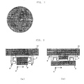
FIG. 5 (a) is a schematic view showing awire saw apparatus 20, andFIGS. 5(b) and (c) are schematic views showing simulation results of deformation of the LM guide when an interval of attachment holes and tightening torque of bolts in the LM guide are adjusted; -
FIG. 6 is a graph showing straightness of feed of a work feed table according to Example 1; -
FIG. 7 is a view showing a typical example of nanotopography map of a polished silicon wafer according to Example 2; and -
FIG. 8(a) is a view for explaining an example where a direction of bolts used to attach the LM guide to the wire saw apparatus is set to be perpendicular to a wire traveling direction andFIG. 8 (b) is a view for explaining an example where a direction of the LM guide attachment bolts is set to be parallel to the wire traveling direction when the wire saw apparatus is seen from above. - The present invention will now be explained hereinafter.
As explained above, in nanotopography (slice waviness) caused due to slicing using a wire saw, waviness having periodicity was often rejected in nanotopography sensory test, but a cause of occurrence of such waviness was unknown, and hence an improvement was difficult.
The present inventors discovered that this cause is straightness of feed of a work feed table and the straightness correlates with the slice waviness having periodicity. - The present inventors conducted the following experiment to find out this cause when achieving the present invention.
That is, the straightness of feed of the work feed table in a wire saw apparatus was measured by using a straight edge and an electric micrometer. Specifically, the straight edge was attached to the work feed table, and a dislocation from a straight line was measured by the electric micrometer while feeding the work feed table approximately 300 mm by an LM guide (a linear-motion guide).FIG. 3 shows its result. A line (a) inFIG. 3 represents straightness of feed of the work feed table before performing a later-explained improvement. It can be understood that a waviness component (a PV value: 0.63 µm) having a wavelength of 14 mm corresponding to a pitch of a cylindrical runner overlaps a long-period waviness component (a PV value : 1.63 µm) having a wavelength of approximately 100 mm in the line (a) On the other hand, a line (b) inFIG. 3 represents straightness of feed of the work feed table having improved roundness of a cylindrical runner used for the LM guide. In the line (b), the waviness component having the wavelength of 14 mm corresponding to the pitch of the cylindrical runner is reduced to 1/3 or below of that before the improvement. As a result, the entire straightness becomes 1.48 µm/300 mm, and the improvement can be observed. However, a value 1.48 µm as the PV value was insufficient for an improving effect. - Thus, when the graph of straightness of feed of the work feed table in the wire saw apparatus depicted in
FIG. 3 was compared with "slice waviness having periodicity" observed in nanotopography map in a polished silicon wafer having a diameter of 300 mm sliced by using this wire saw apparatus and their correlation was checked, the following facts were revealed. That is, as indicated by dotted lines inFIG. 4 , the "slice waviness having periodicity" observed in the nanotopography map in the polished silicon wafer well matched with a long-period component of straightness of feed of the work feed table. The present inventors discovered from this result a possibility of being able to reduce further the "slice waviness having periodicity" by improving the long-period component of straightness of feed of the work feed table. On the other hand, it was found that short-period waviness having a wavelength of 14 mm has a small influence on the nanotopography of the polished wafer. - The present inventors conceived that improving straightness (especially long-period waviness having a wavelength which exceeds 14 mm and is such as 20 to 200 mm) of the work feed table enables improving the nanotopography of a wafer surface, thereby bringing the present invention to completion.
- Although an embodiment according to the present invention will now be explained hereinafter, the present invention is not restricted thereto.
FIG. 1 is a schematic view showing an example of a wire saw apparatus according to the present invention. - The feature of this
wire saw apparatus 10 is that it includes at least awire row 1 formed by winding a wire saw aroundgroove rollers 5, a work feed table 3 for holding and feeding aningot 2 to thewire row 1, and anLM guide 4 for linearly guiding the work feed table 3, and a component having a wavelength of 20 to 200 mm as a long-period component in straightness of feed of the work feed table 3 satisfies a PV value ≤ 1.0 µm. Thewire saw apparatus 10 has such a structure to enable manufacturing a wafer having an improved nanotopography of a surface thereof. - Although straightness of short-period waviness having a short wavelength, e.g., the wavelength of 14 mm can be improved by improving roundness of a cylindrical runner, an improving effect is small in nanotopography of a polished wafer. Further, since long-period waviness having a long wavelength exceeding a diameter of a wafer, e.g., 200 to 300 mm has a small influence in the polished wafer, a component with a wavelength of 20 to 200 mm satisfying the PV value ≤ 1.0 µm can suffice. Incidentally, in the component having the wavelength of 20 to 200 mm, the smaller PV value is preferable.
- Such a wire saw apparatus according to the present invention can be realized by improving straightness of feed of the work feed table in a conventional wire saw apparatus by, e.g., using a later-explained method according to the present invention.
- Furthermore, according to a method of improving the nanotopography of the present invention, improving straightness of feed of the work feed table used for feeding the ingot to the wire row enables improving the nanotopography of the wafer surface. Such an improvement in straightness of feed of the work feed table can be carried out by, e.g., improving straightness of the work feed table or the LM guide itself, improving an attachment precision of the LM guide with respect to the wire saw apparatus, improving deformation of the LM guide, or improving roundness of the cylindrical runner. For example, as specific precision improvement methods, there are methods of:
- (a) adjusting an interval between attachment holes and tightening torque of bolts in the LM guide; and
- (b) setting a direction of attachment bolts of the LM guide in parallel with a wire traveling direction to reduce an influence on waviness due to deformation of the LM guide.
A direction 8' of bolts which are used to attach an LM guide 4' to an LM guide attachment column 21' of the wire saw apparatus is perpendicular to a wire traveling direction 9' as inFIG. 8(a) in such a conventional wire saw apparatus 10' depicted inFIG. 2 , but adirection 8 of bolts which are used to attach anLM guide 4 to an LMguide attachment column 21 is set in parallel to awire traveling direction 9 as inFIG. 8 (b) in such a wire sawapparatus 10 according to the present invention as shown inFIG. 1 about the method (b), thereby reducing an influence of deformation of theLM guide 4 on the waviness. - For example, in such a wire saw
apparatus 20 including a work feed table 13 which is used for feeding aningot 12 to awire row 11 formed by winding a wire aroundgroove rollers 15 as shown inFIG. 5 (a) ,intervals 17 between attachment holes 16 and tightening torque of bolts (not shown) in anLM guide 14 were changed to simulate its effect based on a finite element method. Then, it was confirmed in the simulation that deformation of theLM guide 14 was improved as shown inFIGS. 5(b) and (c) and straightness of feed was improved from 2.5 µm/300 mm to 1.2 µm/300 mm when the intervals of the attachment holes and the tightening torque of the bolts in the LM guide were changed from 100 mm and 60 Nm (FIG. 5 (b) ) to 75 mm and 40 Nm (FIG. 5(c) ). - In this manner, straightness of feed of the work feed table can be assuredly improved by improving deformation of the linear-motion guide for linearly guiding the work feed table and, in particular, this deformation of the linear-motion guide can be more assuredly improved by adjusting intervals of the attachment holes which are used to attach the linear-motion guide to the wire saw apparatus by using bolts and tightening torque of the bolts.
- Although the present invention will now be specifically explained based on examples of the present invention and comparative examples hereinafter, the present invention is not restricted thereto.
- In the wire saw apparatus shown in
FIG. 1 , intervals of attachment holes which are used to attach an LM guide to the wire saw apparatus by using the bolts and tightening torque of bolts were respectively adjusted from 100 mm and 60 Nm (Comparative Example 1) to 75 mm and 40 Nm (Example 1) like the above-explained simulation. Further, straightness of feed of the work feed table was measured by the same method as above. - As a result, while straightness of feed of the work feed table was 1.48 µm/300 mm and a component having a wavelength of approximately 100 mm was 1.48 µm in terms of a PV value in Comparative Example 1, straightness of feed of the work feed table was 0.92 µm/300 mm and a component having a wavelength of approximately 100 mm was 0.92 µm in terms of the PV value in Example 1 as shown in
FIG. 6 , thereby providing the wire saw apparatus having the greatly improved straightness of feed of the work feed table. Based on a result depicted inFIG. 6 , if waviness at a work feed start position can be adjusted, a further improvement can be expected. - The wire saw apparatuses in Example 1 and Comparative Example 1 were utilized to slice a silicon ingot having a diameter of 300 mm under conditions whose an outline is shown in Table 1, and the sliced ingots were polished to obtain silicon wafers (Example 2, Comparative Example 2).
FIG. 7 shows a typical example of nanotopography map of the polished silicon wafer according to Example 2. Moreover, Table 2 shows N numbers of the wafers and frequencies of occurrence of "slice waviness having periodicity" as a problem with a frequency of occurrence in Comparative Example 2 being determined as 100%. The frequency of occurrence of "slice waviness having periodicity" in Example 2 was improved to approximately 1/10 of that in Comparative Example 2 by improving straightness of feed of the work feed table carried out in Example 1. -
[Table 1] Item Condition Work Ingot diameter 300 mm Wire Wire diameter 160 µm Wire tension 2.8 kgf New wire line supply amount 100 m/min Wire reversal cycle 60 s Wire traveling speed 500 m/min (average) Slurry Abrasive grain GC#1000 Abrasive grain concentration (coolant: abrasive grain) 50: 50 (weight ratio) Slurry temperature 25.0°C (constant) -
[Table 2] Frequency of occurrence of slice waviness having periodicity Comparative Example 2 N number 762 Average value 100% Example 2 N number 240 Average value 10% - It is to be noted that the present invention is not restricted to the foregoing embodiment. The foregoing embodiment is just an example, and any embodiment having substantially the same feature as that in a technical concept described in claims of the present invention and demonstrating the same functions and effect is included in a technical scope of the present invention.
- For example, although the example where straightness of feed of the work feed table is improved mainly by adjusting an interval between the attachment holes and the tightening torque of the bolts in the linear-motion guide has been explained above, the present invention is not restricted thereto, and any method can be adopted as long as straightness of feed of the work feed table can be improved.
- That is, according to the present invention, since slice waviness having periodicity can be improved if straightness of feed of the work feed table can be improved, the method of improving straightness of feed of the work feed table is not restricted in particular.
Claims (4)
- A method of improving nanotopography of a surface of a wafer sliced from an ingot by using a wire saw apparatus, at least comprising improving straightness of feed of a work feed table which is included in the wire saw apparatus and used for feeding the ingot to a wire row formed by winding a wire around a plurality of rollers.
- The method of improving nanotopography of a surface of a wafer according to claim 1, wherein straightness of feed of the work feed table is improved by improving deformation of a linear-motion guide for linearly guiding the work feed table.
- The method of improving nanotopography of a surface of a wafer according to claim 2, wherein deformation of the linear-motion guide is improved by adjusting an interval between attachment holes and tightening torque of bolts, and the holes are used to attach the linear-motion guide to the wire saw apparatus by using the bolts.
- A wire saw apparatus for slicing an ingot to manufacture a wafer, comprising at least: a wire row formed by winding a wire around a plurality of rollers; a work feed table for holding and feeding the ingot to the wire row; and a linear-motion guide for linearly guiding the work feed table, wherein a component having a wavelength of 20 to 200 mm in straightness of feed of the work feed table satisfies a PV value ≤ 1.0 µm.
Applications Claiming Priority (2)
| Application Number | Priority Date | Filing Date | Title |
|---|---|---|---|
| JP2005252180A JP5072204B2 (en) | 2005-08-31 | 2005-08-31 | Method and wire saw apparatus for improving nanotopography of wafer surface |
| PCT/JP2006/315706 WO2007026512A1 (en) | 2005-08-31 | 2006-08-09 | Method of improving nanotopography on surface of wafer and wire saw device |
Publications (3)
| Publication Number | Publication Date |
|---|---|
| EP1920885A1 true EP1920885A1 (en) | 2008-05-14 |
| EP1920885A4 EP1920885A4 (en) | 2010-08-18 |
| EP1920885B1 EP1920885B1 (en) | 2017-02-08 |
Family
ID=37808614
Family Applications (1)
| Application Number | Title | Priority Date | Filing Date |
|---|---|---|---|
| EP06782522.4A Ceased EP1920885B1 (en) | 2005-08-31 | 2006-08-09 | Method of improving nanotopography of surface of wafer and wire saw apparatus |
Country Status (6)
| Country | Link |
|---|---|
| US (1) | US7997262B2 (en) |
| EP (1) | EP1920885B1 (en) |
| JP (1) | JP5072204B2 (en) |
| KR (1) | KR101283393B1 (en) |
| CN (1) | CN101253021B (en) |
| WO (1) | WO2007026512A1 (en) |
Cited By (1)
| Publication number | Priority date | Publication date | Assignee | Title |
|---|---|---|---|---|
| DE102013210882B3 (en) | 2013-06-11 | 2014-08-21 | Solarworld Innovations Gmbh | Device for sawing silicon ingots in wafer, has guiding device for form-fit guiding of ingots, and another guiding device for guiding sawed wafer, where guiding devices are arranged on opposite sides of wire field of wire saw |
Families Citing this family (15)
| Publication number | Priority date | Publication date | Assignee | Title |
|---|---|---|---|---|
| US8697576B2 (en) | 2009-09-16 | 2014-04-15 | Cabot Microelectronics Corporation | Composition and method for polishing polysilicon |
| US8883034B2 (en) | 2009-09-16 | 2014-11-11 | Brian Reiss | Composition and method for polishing bulk silicon |
| US8815110B2 (en) | 2009-09-16 | 2014-08-26 | Cabot Microelectronics Corporation | Composition and method for polishing bulk silicon |
| CN102126261A (en) * | 2010-06-10 | 2011-07-20 | 常州天合光能有限公司 | Wire saw with cutting function |
| EP2583804A1 (en) * | 2011-10-22 | 2013-04-24 | Applied Materials Switzerland Sàrl | A new wafer sawing system |
| US9156187B2 (en) | 2011-12-29 | 2015-10-13 | Sunedison Semiconductor Ltd. | Methods for mounting an ingot on a wire saw |
| CN102773932A (en) * | 2012-08-09 | 2012-11-14 | 王卫锋 | Rocking multiwire cutting machine |
| US9597819B2 (en) * | 2012-09-03 | 2017-03-21 | Hitachi Metals, Ltd. | Method for cutting high-hardness material by multi-wire saw |
| CN103522431B (en) * | 2013-10-21 | 2015-08-05 | 山西潞安太阳能科技有限责任公司 | A kind of silicon chip cutting technique |
| JP5994766B2 (en) * | 2013-11-21 | 2016-09-21 | 信越半導体株式会社 | Work cutting method |
| JP6304118B2 (en) * | 2015-05-01 | 2018-04-04 | 信越半導体株式会社 | Wire saw equipment |
| CN108608591A (en) * | 2016-12-12 | 2018-10-02 | 上海新昇半导体科技有限公司 | Improve the System of HS-WEDM of crystal column surface cutting pattern |
| JP6443520B1 (en) * | 2017-10-02 | 2018-12-26 | 株式会社Sumco | Semiconductor wafer evaluation method and semiconductor wafer manufacturing method using the method |
| DE102018221922A1 (en) * | 2018-12-17 | 2020-06-18 | Siltronic Ag | Method for producing semiconductor wafers using a wire saw, wire saw and semiconductor wafer made of single-crystal silicon |
| CN115107177B (en) * | 2022-05-31 | 2024-07-02 | 浙江晶盛机电股份有限公司 | Precision compensation method and slicer |
Family Cites Families (9)
| Publication number | Priority date | Publication date | Assignee | Title |
|---|---|---|---|---|
| JP3539773B2 (en) | 1994-09-19 | 2004-07-07 | 信越化学工業株式会社 | Wire saw and cutting method with wire saw |
| JP2891187B2 (en) | 1995-06-22 | 1999-05-17 | 信越半導体株式会社 | Wire saw device and cutting method |
| JPH10249700A (en) * | 1997-03-17 | 1998-09-22 | Super Silicon Kenkyusho:Kk | Method and apparatus for cutting ingot by wire saw |
| US6371101B1 (en) * | 1997-05-07 | 2002-04-16 | Hct Shaping Systems Sa | Slicing device using yarn for cutting thin wafers using the angular intersection of at least two yarn layers |
| JP2000304040A (en) * | 1999-04-22 | 2000-10-31 | Asahi Optical Co Ltd | Linear guide fixing structure |
| CN1193409C (en) * | 2000-11-16 | 2005-03-16 | 信越半导体株式会社 | Wafer shape evaluation method |
| JP2002254284A (en) * | 2001-02-23 | 2002-09-10 | Nippei Toyama Corp | Wire saw |
| JP4248895B2 (en) * | 2003-02-27 | 2009-04-02 | Sumco Techxiv株式会社 | Slurry regeneration method and wire saw system |
| US7306508B2 (en) | 2003-10-27 | 2007-12-11 | Mitsubishi Denki Kabushiki Kaisha | Multi-wire saw |
-
2005
- 2005-08-31 JP JP2005252180A patent/JP5072204B2/en not_active Expired - Lifetime
-
2006
- 2006-08-09 US US11/990,622 patent/US7997262B2/en active Active
- 2006-08-09 WO PCT/JP2006/315706 patent/WO2007026512A1/en not_active Ceased
- 2006-08-09 CN CN2006800318696A patent/CN101253021B/en not_active Expired - Fee Related
- 2006-08-09 KR KR1020087005087A patent/KR101283393B1/en not_active Expired - Fee Related
- 2006-08-09 EP EP06782522.4A patent/EP1920885B1/en not_active Ceased
Cited By (1)
| Publication number | Priority date | Publication date | Assignee | Title |
|---|---|---|---|---|
| DE102013210882B3 (en) | 2013-06-11 | 2014-08-21 | Solarworld Innovations Gmbh | Device for sawing silicon ingots in wafer, has guiding device for form-fit guiding of ingots, and another guiding device for guiding sawed wafer, where guiding devices are arranged on opposite sides of wire field of wire saw |
Also Published As
| Publication number | Publication date |
|---|---|
| KR101283393B1 (en) | 2013-07-08 |
| JP2007061968A (en) | 2007-03-15 |
| KR20080038197A (en) | 2008-05-02 |
| WO2007026512A1 (en) | 2007-03-08 |
| US7997262B2 (en) | 2011-08-16 |
| CN101253021A (en) | 2008-08-27 |
| JP5072204B2 (en) | 2012-11-14 |
| EP1920885B1 (en) | 2017-02-08 |
| US20100180880A1 (en) | 2010-07-22 |
| CN101253021B (en) | 2011-02-09 |
| EP1920885A4 (en) | 2010-08-18 |
Similar Documents
| Publication | Publication Date | Title |
|---|---|---|
| EP1920885B1 (en) | Method of improving nanotopography of surface of wafer and wire saw apparatus | |
| KR101476670B1 (en) | Cutting method and wire saw device | |
| KR101402721B1 (en) | Cutting Method | |
| KR101362864B1 (en) | Cutting Method | |
| US20140318522A1 (en) | Method for slicing workpiece | |
| US9579826B2 (en) | Method for slicing wafers from a workpiece using a sawing wire | |
| US9776340B2 (en) | Method for slicing ingot and wire saw | |
| CN103507173B (en) | Cut the method for multiple wafer from cylindrical workpiece simultaneously | |
| CN103842129A (en) | Workpiece cutting method and wire saw | |
| EP4347207B1 (en) | Method for simultaneously cutting a plurality of disks from a workpiece | |
| JP6235295B2 (en) | Fixed abrasive wire saw apparatus and wafer manufacturing method using the same | |
| EP2815834A1 (en) | Wire monitoring system for a wire saw and method for monitoring a wire saw | |
| JP2000218504A (en) | Wire with fixed abrasive grains and cutting method for fixed abrasive grains wire saw | |
| JP2000288902A (en) | Wire with fixed abrasive grains and fixed abrasive grain wire saw | |
| JP5876388B2 (en) | Workpiece cutting method | |
| JP2011166154A (en) | Method for cutting multiple wafers from crystal formed from semiconductor material | |
| WO2013041140A1 (en) | Method and apparatus for cutting semiconductor workpieces | |
| KR20230041784A (en) | Method and apparatus for simultaneously separating a plurality of disks from a workpiece | |
| JP6705399B2 (en) | Wafer manufacturing method | |
| JP2013082020A (en) | Workpiece cutting method, method of manufacturing semiconductor substrate, semiconductor substrate, and wire saw device | |
| JP2002052455A5 (en) | ||
| US20070259607A1 (en) | Method and cutting and lapping a workpiece | |
| JPH11114799A (en) | Cutting method and apparatus | |
| JP2004243509A (en) | Method for working flat face by fiber of abrasive contents (wire saw) |
Legal Events
| Date | Code | Title | Description |
|---|---|---|---|
| PUAI | Public reference made under article 153(3) epc to a published international application that has entered the european phase |
Free format text: ORIGINAL CODE: 0009012 |
|
| 17P | Request for examination filed |
Effective date: 20080226 |
|
| AK | Designated contracting states |
Kind code of ref document: A1 Designated state(s): DE |
|
| DAX | Request for extension of the european patent (deleted) | ||
| RBV | Designated contracting states (corrected) |
Designated state(s): DE |
|
| A4 | Supplementary search report drawn up and despatched |
Effective date: 20100720 |
|
| 17Q | First examination report despatched |
Effective date: 20140630 |
|
| RAP1 | Party data changed (applicant data changed or rights of an application transferred) |
Owner name: SHIN-ETSU HANDOTAI CO., LTD. |
|
| GRAP | Despatch of communication of intention to grant a patent |
Free format text: ORIGINAL CODE: EPIDOSNIGR1 |
|
| INTG | Intention to grant announced |
Effective date: 20160919 |
|
| STAA | Information on the status of an ep patent application or granted ep patent |
Free format text: STATUS: GRANT OF PATENT IS INTENDED |
|
| GRAS | Grant fee paid |
Free format text: ORIGINAL CODE: EPIDOSNIGR3 |
|
| GRAA | (expected) grant |
Free format text: ORIGINAL CODE: 0009210 |
|
| STAA | Information on the status of an ep patent application or granted ep patent |
Free format text: STATUS: THE PATENT HAS BEEN GRANTED |
|
| AK | Designated contracting states |
Kind code of ref document: B1 Designated state(s): DE |
|
| REG | Reference to a national code |
Ref country code: DE Ref legal event code: R096 Ref document number: 602006051702 Country of ref document: DE |
|
| REG | Reference to a national code |
Ref country code: DE Ref legal event code: R097 Ref document number: 602006051702 Country of ref document: DE |
|
| PLBE | No opposition filed within time limit |
Free format text: ORIGINAL CODE: 0009261 |
|
| STAA | Information on the status of an ep patent application or granted ep patent |
Free format text: STATUS: NO OPPOSITION FILED WITHIN TIME LIMIT |
|
| 26N | No opposition filed |
Effective date: 20171109 |
|
| PGFP | Annual fee paid to national office [announced via postgrant information from national office to epo] |
Ref country code: DE Payment date: 20230627 Year of fee payment: 18 |
|
| REG | Reference to a national code |
Ref country code: DE Ref legal event code: R119 Ref document number: 602006051702 Country of ref document: DE |
|
| PG25 | Lapsed in a contracting state [announced via postgrant information from national office to epo] |
Ref country code: DE Free format text: LAPSE BECAUSE OF NON-PAYMENT OF DUE FEES Effective date: 20250301 |