EP1920704A1 - Receiver apparatus - Google Patents
Receiver apparatus Download PDFInfo
- Publication number
- EP1920704A1 EP1920704A1 EP06796985A EP06796985A EP1920704A1 EP 1920704 A1 EP1920704 A1 EP 1920704A1 EP 06796985 A EP06796985 A EP 06796985A EP 06796985 A EP06796985 A EP 06796985A EP 1920704 A1 EP1920704 A1 EP 1920704A1
- Authority
- EP
- European Patent Office
- Prior art keywords
- recording medium
- portable recording
- receiving
- signal
- warning
- Prior art date
- Legal status (The legal status is an assumption and is not a legal conclusion. Google has not performed a legal analysis and makes no representation as to the accuracy of the status listed.)
- Withdrawn
Links
- 0 C[C@]1CC(*)CC1 Chemical compound C[C@]1CC(*)CC1 0.000 description 1
Images



Classifications
-
- A—HUMAN NECESSITIES
- A61—MEDICAL OR VETERINARY SCIENCE; HYGIENE
- A61B—DIAGNOSIS; SURGERY; IDENTIFICATION
- A61B1/00—Instruments for performing medical examinations of the interior of cavities or tubes of the body by visual or photographical inspection, e.g. endoscopes; Illuminating arrangements therefor
- A61B1/04—Instruments for performing medical examinations of the interior of cavities or tubes of the body by visual or photographical inspection, e.g. endoscopes; Illuminating arrangements therefor combined with photographic or television appliances
- A61B1/041—Capsule endoscopes for imaging
-
- A—HUMAN NECESSITIES
- A61—MEDICAL OR VETERINARY SCIENCE; HYGIENE
- A61B—DIAGNOSIS; SURGERY; IDENTIFICATION
- A61B1/00—Instruments for performing medical examinations of the interior of cavities or tubes of the body by visual or photographical inspection, e.g. endoscopes; Illuminating arrangements therefor
- A61B1/00002—Operational features of endoscopes
- A61B1/00011—Operational features of endoscopes characterised by signal transmission
- A61B1/00016—Operational features of endoscopes characterised by signal transmission using wireless means
-
- A—HUMAN NECESSITIES
- A61—MEDICAL OR VETERINARY SCIENCE; HYGIENE
- A61B—DIAGNOSIS; SURGERY; IDENTIFICATION
- A61B1/00—Instruments for performing medical examinations of the interior of cavities or tubes of the body by visual or photographical inspection, e.g. endoscopes; Illuminating arrangements therefor
- A61B1/00002—Operational features of endoscopes
- A61B1/00025—Operational features of endoscopes characterised by power management
- A61B1/00036—Means for power saving, e.g. sleeping mode
-
- A—HUMAN NECESSITIES
- A61—MEDICAL OR VETERINARY SCIENCE; HYGIENE
- A61B—DIAGNOSIS; SURGERY; IDENTIFICATION
- A61B1/00—Instruments for performing medical examinations of the interior of cavities or tubes of the body by visual or photographical inspection, e.g. endoscopes; Illuminating arrangements therefor
- A61B1/00002—Operational features of endoscopes
- A61B1/00043—Operational features of endoscopes provided with output arrangements
- A61B1/00055—Operational features of endoscopes provided with output arrangements for alerting the user
-
- A—HUMAN NECESSITIES
- A61—MEDICAL OR VETERINARY SCIENCE; HYGIENE
- A61B—DIAGNOSIS; SURGERY; IDENTIFICATION
- A61B5/00—Measuring for diagnostic purposes; Identification of persons
- A61B5/07—Endoradiosondes
- A61B5/073—Intestinal transmitters
-
- A—HUMAN NECESSITIES
- A61—MEDICAL OR VETERINARY SCIENCE; HYGIENE
- A61B—DIAGNOSIS; SURGERY; IDENTIFICATION
- A61B2560/00—Constructional details of operational features of apparatus; Accessories for medical measuring apparatus
- A61B2560/04—Constructional details of apparatus
- A61B2560/0475—Special features of memory means, e.g. removable memory cards
Definitions
- the present invention relates to a receiving apparatus that receives a radio signal transmitted from a body-insertable apparatus such as a capsule endoscope to be introduced into a subject, and records the radio signal on a portable recording medium detachably attached thereto.
- image data acquired in the body cavity by the capsule endoscope is sequentially transmitted to the outside of the examinee by the radio communication function such as radio communications, and stored in a memory provided in an external receiving device. If the examinee carries the receiving device having the radio communication function and the memory function, the examinee swallows the capsule endoscope and then can freely move without any inconvenience even during the observation period until the endoscope is discharged. After the observation, a doctor or a nurse can perform diagnosis by displaying images of the body cavity on a display unit, such as a display, based on the image data stored in the memory in the receiving device (see Patent Document 1).
- Patent Document 1 Japanese Patent Application Laid-open No. 2003-19111
- a portable recording medium such as a CompactFlash® Memory, which is detachable relative to a receiver and a display device such as a workstation, and has a structure capable of outputting or recording information at the time of being set in both the receiver and the workstation.
- the portable recording medium is set in the receiver attached to the subject to record data transmitted from the capsule endoscope, and after the capsule endoscope is discharged from the subject, the portable recording medium is taken out from the receiver and set in the display device, so that the display device reads the data recorded on the portable recording medium. Since transfer of data between the receiver and the display device is performed by the portable recording medium, the subject can freely moves during taking pictures of the body cavity, which also contributes to reduction of a transfer period of data between the receiver and the display device.
- the portable recording medium is detachable to the receiver, even while the data of the body cavity imaged by the capsule endoscope is being received and recorded, if a user (such as a doctor, a nurse, or a patient) wishes to eject the portable recording medium from the receiver, the portable recording medium can be ejected. If the portable recording medium is erroneously ejected from the receiver during receiving and recording data (during examination), the receiver cannot record and store the imaged data of the body cavity transmitted from the capsule endoscope and received, and hence the sequentially acquired valuable imaged data of the body cavity for the examination is lost. In other words, since the examination by the capsule endoscope extends over a long time, for example, about eight hours, the examination cannot be redone.
- the present invention has been achieved to solve the above problems, and it is an object of the present invention to provide a receiving apparatus that can prevent beforehand the portable recording medium from being erroneously ejected, and can prevent the imaged data of the body cavity from being lost and the portable recording medium from being damaged.
- a receiving apparatus receives a radio signal transmitted from a body-insertable apparatus introduced into a subject, and records the radio signal on a portable recording medium detachably attached thereto, and includes an in-operation detector that detects that a recording operation is in progress, an ejection operation detector that detects an ejection operation of the portable recording medium, a warning unit that gives a warning to a user, and a control unit that operates the warning unit before the portable recording medium is ejected, when the ejection operation of the portable recording medium is detected during the recording operation.
- the portable recording medium is detachably attached by a plurality of operations or actions, and the ejection operation detector detects the ejection operation of the portable recording medium, at the time of starting the first one of the plurality of operations or actions.
- the warning unit generates a warning by a warning display on a display unit.
- the warning unit generates a warning by lighting-on or blinking of a light emission element.
- the light emission element is provided near an ejector of the portable recording medium.
- the warning unit generates a warning by a warning sound.
- the warning unit when the ejection operation of the portable recording medium is detected, the warning unit is operated before the portable recording medium is ejected to give a warning to the user so that the ejection operation is not performed. Accordingly, it can be prevented beforehand that the portable recording medium is erroneously ejected during the recording operation, and hence it can be prevented that the imaged data of the body cavity is lost and the portable recording medium is damaged.
- Fig. 1 is a schematic diagram of an overall configuration diagram of a wireless in-vivo information acquiring system according to a first embodiment of the present invention.
- the wireless in-vivo information acquiring system uses a capsule endoscope as one example of the body-insertable apparatus, which is a transmitting unit.
- the wireless in-vivo information acquiring system includes a receiving apparatus 2 having a radio receiving function, and a capsule endoscope 3 introduced into a subject 1 to take pictures of body cavity images and transmits data such as an image signal to the receiving apparatus 2.
- the wireless in-vivo information acquiring system also includes a display device 4 that displays the body cavity image based on the image signal received by the receiving apparatus 2, and a portable recording medium 5 for transferring data between the receiving apparatus 2 and the display device 4.
- the receiving apparatus 2 includes an antenna unit 2a including a plurality of receiving antennas A1 to An attached to the body surface of the subject 1, and a main receiving unit 2b as a main receiving apparatus that performs processing of radio signals received via the receiving antennas A1 to An, and these units are detachably connected with each other via a connector or the like.
- the receiving antennas A1 to An can be equipped on a receiving jacket wearable by the subject, and the subject 1 can carry the receiving antennas A1 to An by wearing the receiving jacket. In this case, the receiving antennas A1 to An can be detachable to the jacket.
- the display device 4 displays the body cavity images and the like taken by the capsule endoscope 3, and has a configuration of a workstation or the like that displays images based on data acquired by the portable recording medium 5.
- the display device 4 can have a configuration such that images are directly displayed by a CRT display, a liquid crystal display, or the like, or a configuration such that images are output to other media, like a printer.
- the portable recording medium 5 can be prevented beforehand that the portable recording medium 5 is erroneously ejected during the recording operation, and hence the body cavity image data can be prevented from being lost and the portable recording medium can be prevented from being damaged.
- two actions are required for ejecting the portable recording medium 5, and the ejection operation is detected at the time of starting the opening operation of the card cover 22, which is the first operation, and at this point in time, a warning so as not to perform the ejection operation is generated before the portable recording medium 5 is pulled out from the connector. Accordingly, the portable recording medium 5 can be prevented beforehand from being detached from the connector during the recording operation.
- the warning is generated by the LED 23 provided near the card insertion port 21, from which the portable recording medium 5 is ejected, a warning so as not to perform ejection can be given to the user effectively.
- the control unit C has a selection controller C1, which connects a storage unit 113, a display unit 114, and a switching controller SC corresponding to the signal processing circuit 112, the A/D converter 116, and the portable recording medium 105 to each other.
- the switching controller SC has strength-receiving-antenna number information N1 and image-receiving-antenna number information N2, generates a changeover instruction of the changeover switch SW based on these pieces of number information, and instructs a processing timing of the sample-hold circuit 115, the A/D converter 116, and the selection controller C1.
- a power supply unit 117 supplies power to respective units, and is achieved by a battery, for example.
- the selection controller C1 in the control unit C selects a receiving antenna, which has received the largest received electric-field strength of the electric-field strength received during a part of the synchronization period and a horizontal blanking period in the image signal period as a receiving antenna in the image signal period. Further, the selection controller C1 sequentially selects a receiving antenna other than the selected receiving antenna as the receiving antenna during a part of the synchronization period and the horizontal blanking period in the image signal period, and outputs a signal S4, in which the respective receiving antenna numbers are designated as strength-receiving-antenna number information N1 and image-receiving-antenna number information N2, to the switching controller SC.
- the control unit C stores the received electric-field strength during a part of the synchronization period and the horizontal blanking period in the image signal period and the received electric-field strength during an image receiving period excluding at least the horizontal blanking period in the storage unit 113 in correspondence with the receiving antenna selected at that time, together with the image data.
- the stored received electric-field strength of respective receiving antennas becomes information for calculating the position of the capsule endoscope 103 in the subject when the image data is received.
- the switching controller SC outputs a signal S5 instructing the changeover switch SW so as to selectively connect any one of the receiving antennas A1 to An corresponding to the image-receiving-antenna number information N2 during the image receiving period excluding at least the horizontal blanking period, to the changeover switch SW, and outputs a signal S3a instructing a sample-hold timing by the sample-hold circuit 115, a signal S3b instructing an A/D conversion timing by the A/D converter 116, and a signal S3c instructing a selection control by the selection controller C1.
- the signal processing circuit 112 is explained with reference to Fig. 8 .
- the signal processing circuit 112 has a function for performing predetermined processing with respect to the body cavity image data wirelessly transmitted from the capsule endoscope 103 and received, and storing the body cavity image data in the storage unit 113 (the portable recording medium 105) after subjecting the image data to compression processing and the like.
- Fig. 8 is a block diagram schematically showing a configuration of the signal processing circuit 112.
- the signal processing circuit 112 includes the clock recovery 161 to which the image signal from the receiving apparatus 11 is input, an S/P converter 162, a synchronization detector 163, an image generator 164 connected to the output side of the S/P converter 162, a WB/ID position detector 165, a frame memory 166 connected to the output side of the image generator 164, an error correcting unit 167 connected to the output side of the WB/ID position detector 165, and an image processor 168 connected to the frame memory 166 and the error correcting unit 167 to output a processing result to the control unit C.
- the synchronization detector 163 Upon detection of, for example, the code "55 AA FF 55", the synchronization detector 163 outputs a pulse of the horizontal synchronization signal HD to the image generator 164.
- the image generator 164 generates frame image data by performing the image generation processing with respect to the parallel-converted image signal at a timing synchronized with the vertical synchronization signal VD and the horizontal synchronization signal HD, and temporarily stores the frame image data in the frame memory 166.
- the image processor 168 uses the error-corrected white balance factor data "WB" to perform white balance processing and required image processing such as compression processing, with respect to the frame image data generated and temporarily stored in the frame memory 166, and stores the data in the storage unit 113 (the portable recording medium 105) under control of the control unit C. At the time of such image processing, the image processor 168 checks the error-corrected ID information "ID" specific to the capsule, and when the ID information "ID" does not agree with the ID information "ID” specific to the capsule in the previous frame, determines that the image data is transmitted from another capsule endoscope 103, so that the image data is not stored in the storage unit 113 (the portable recording medium 105).
- the Reed-Solomon codes "RS1" and “RS2” are added to the white balance factor information "WB” specific to the capsule endoscope 103 and the ID information "ID” specific to the capsule for deciding the capsule endoscope 103 and transmitted.
- the Reed-Solomon codes "RS1” and “RS2” are used to perform error correction of the white balance factor information "WB” and the ID information "ID” specific to the capsule. Accordingly, even if a bit error such as data garbling occurs in the white balance factor information "WB” and the ID information "ID” specific to the capsule, the information can be corrected to right data by the error correction processing.
- the 16-bit code of "55 AA FF 55" is used as the code indicating the horizontal synchronization signal HSYNC (HV), and the horizontal synchronization signal HSYNC (HV) is set so as to be allocated to particular line positions specified by "0", “1", “2", and “3” as count values HCOUNT of the horizontal synchronization signal in the phase having the count value VCOUNT of "11" since start of the operation, and transmitted, and the Reed-Solomon codes "RS5", and “RS6” for error correction are set so as to be allocated to particular line positions specified by "4" and "5" as count values HCOUNT immediately thereafter, and transmitted.
- the synchronization-code-position detecting shift register 171 detects whether the count values VCOUNT and HCOUNT have reached the count value VCOUNT "10" and the count values HCOUNT "350” to "353" where the code indicating the vertical synchronization signal VD should be present, while shifting the image signal S1 input corresponding to the clock, and when the count values have reached these positions, receives 6-byte data including the Reed-Solomon codes "RS3" and "RS4" immediately thereafter.
- the error correcting unit 172 performs error correction with respect to a code indicating the vertical synchronization signal VD by the Reed-Solomon codes "RS3" and "RS4" by using the received 6-byte data.
- the code comparator 173 compares and determines whether the error-corrected code indicating the vertical synchronization signal VD agrees with the code "55 00 FF 55" indicating the original vertical synchronization signal VD. When these codes agrees with each other, the code comparator 173 determines that the code has been detected correctly and outputs a pulse of the vertical synchronization signal VD to the image generator 164 and the WB/ID position detector 165. Accordingly, even if there is a bit error in the code indicating the vertical synchronization signal VD, the correct vertical synchronization signal VD can be detected, and the arrangement position of the white balance factor information "WB" and the ID information "ID” specific to the capsule can be correctly detected. The code comparator 73 also outputs the vertical synchronization signal VD to the synchronization-code-position detecting shift register 171, and resets the counter.
- the code comparator 173 compares and determines whether the error-corrected code indicating the horizontal synchronization signal VD agrees with the code "55 AA FF 55" indicating the original horizontal synchronization signal HD. When these codes agree with each other, the code comparator 173 determines that the code has been detected correctly and outputs a pulse of the horizontal synchronization signal HD to the image generator 164. Accordingly, even if there is a bit error in the code indicating the horizontal synchronization signal HD, the correct horizontal synchronization signal HD can be detected, and the line synchronization can be achieved reliably. The code comparator 173 also outputs the horizontal synchronization signal HD to the synchronization-code-position detecting shift register 171, and resets the counter.
- the first to the third embodiments described in this specification can be embodied by combining each other.
- the receiving apparatus is useful at the time of receiving a radio signal transmitted from the body-insertable apparatus such as the capsule endoscope and recording the radio signal on a portable recording medium detachably attached thereto.
- the receiving apparatus is suitable for preventing erroneous operations when the portable recording medium can be ejected even during the examination.
Landscapes
- Health & Medical Sciences (AREA)
- Life Sciences & Earth Sciences (AREA)
- Surgery (AREA)
- Engineering & Computer Science (AREA)
- General Health & Medical Sciences (AREA)
- Public Health (AREA)
- Biomedical Technology (AREA)
- Heart & Thoracic Surgery (AREA)
- Medical Informatics (AREA)
- Molecular Biology (AREA)
- Biophysics (AREA)
- Animal Behavior & Ethology (AREA)
- Physics & Mathematics (AREA)
- Veterinary Medicine (AREA)
- Pathology (AREA)
- Nuclear Medicine, Radiotherapy & Molecular Imaging (AREA)
- Optics & Photonics (AREA)
- Radiology & Medical Imaging (AREA)
- Computer Networks & Wireless Communication (AREA)
- Endoscopes (AREA)
- Measurement Of The Respiration, Hearing Ability, Form, And Blood Characteristics Of Living Organisms (AREA)
Abstract
A receiving apparatus that can prevent beforehand that a portable recording medium is erroneously ejected during examination, and can prevent body cavity image data from being lost and the portable recording medium from being damaged is provided. When an ejection operation of the portable recording medium is detected (step S103: Yes) during a recording operation (step S101: Yes), a warning unit is operated before the portable recording medium is ejected to give a warning to a user so as not to perform the ejection operation (step S105). Accordingly, the portable recording medium can be prevented beforehand from being ejected during the recording operation, thereby preventing body cavity image data from being lost and the portable recording medium from being damaged.
Description
- The present invention relates to a receiving apparatus that receives a radio signal transmitted from a body-insertable apparatus such as a capsule endoscope to be introduced into a subject, and records the radio signal on a portable recording medium detachably attached thereto.
- Recently, in the field of endoscope, a capsule endoscope equipped with an imaging function and a radio communication function has appeared. This capsule endoscope has a configuration of moving in the internal organs (body cavity) such as esophagus, stomach, and small intestine with peristalsis during an observation period after it is swallowed from a mouth of an examinee as a subject of observation (examination) until it is naturally discharged from a living body (human body) of the examinee, and sequentially taking pictures at a predetermined imaging rate by using the imaging function.
- During this observation period while the endoscope is moving in the internal organs, image data acquired in the body cavity by the capsule endoscope is sequentially transmitted to the outside of the examinee by the radio communication function such as radio communications, and stored in a memory provided in an external receiving device. If the examinee carries the receiving device having the radio communication function and the memory function, the examinee swallows the capsule endoscope and then can freely move without any inconvenience even during the observation period until the endoscope is discharged. After the observation, a doctor or a nurse can perform diagnosis by displaying images of the body cavity on a display unit, such as a display, based on the image data stored in the memory in the receiving device (see Patent Document 1).
- Patent Document 1: Japanese Patent Application Laid-open No.
2003-19111 - As a memory provided in the receiver, for example, it has been proposed to use a portable recording medium such as a CompactFlash® Memory, which is detachable relative to a receiver and a display device such as a workstation, and has a structure capable of outputting or recording information at the time of being set in both the receiver and the workstation. In other words, while the capsule endoscope is moving in a body cavity of the subject, the portable recording medium is set in the receiver attached to the subject to record data transmitted from the capsule endoscope, and after the capsule endoscope is discharged from the subject, the portable recording medium is taken out from the receiver and set in the display device, so that the display device reads the data recorded on the portable recording medium. Since transfer of data between the receiver and the display device is performed by the portable recording medium, the subject can freely moves during taking pictures of the body cavity, which also contributes to reduction of a transfer period of data between the receiver and the display device.
- However, since the portable recording medium is detachable to the receiver, even while the data of the body cavity imaged by the capsule endoscope is being received and recorded, if a user (such as a doctor, a nurse, or a patient) wishes to eject the portable recording medium from the receiver, the portable recording medium can be ejected. If the portable recording medium is erroneously ejected from the receiver during receiving and recording data (during examination), the receiver cannot record and store the imaged data of the body cavity transmitted from the capsule endoscope and received, and hence the sequentially acquired valuable imaged data of the body cavity for the examination is lost. In other words, since the examination by the capsule endoscope extends over a long time, for example, about eight hours, the examination cannot be redone. Hence, if the imaged data of the body cavity is lost, such an examination becomes meaningless. Furthermore, if the portable recording medium is ejected during a recording operation, the recording medium itself is damaged, and the imaged data of the body cavity already recorded may not be used. However, if a lock mechanism against ejection of the recording medium is strengthened, not only the structure becomes complicated, but also unloading operability of the recording medium deteriorates. Conventionally, an effective measure against such a state has not been taken.
- The present invention has been achieved to solve the above problems, and it is an object of the present invention to provide a receiving apparatus that can prevent beforehand the portable recording medium from being erroneously ejected, and can prevent the imaged data of the body cavity from being lost and the portable recording medium from being damaged.
- To solve the above problems and achieve the object, a receiving apparatus according to the present invention receives a radio signal transmitted from a body-insertable apparatus introduced into a subject, and records the radio signal on a portable recording medium detachably attached thereto, and includes an in-operation detector that detects that a recording operation is in progress, an ejection operation detector that detects an ejection operation of the portable recording medium, a warning unit that gives a warning to a user, and a control unit that operates the warning unit before the portable recording medium is ejected, when the ejection operation of the portable recording medium is detected during the recording operation.
- In the receiving apparatus according to the present invention, the portable recording medium is detachably attached by a plurality of operations or actions, and the ejection operation detector detects the ejection operation of the portable recording medium, at the time of starting the first one of the plurality of operations or actions.
- In the receiving apparatus according to the present invention, the warning unit generates a warning by a warning display on a display unit.
- In the receiving apparatus according to the present invention, the warning unit generates a warning by lighting-on or blinking of a light emission element.
- In the receiving apparatus according to the present invention, the light emission element is provided near an ejector of the portable recording medium.
- In the receiving apparatus according to the present invention, the warning unit generates a warning by a warning sound.
- According to the receiving apparatus of the present invention, when the ejection operation of the portable recording medium is detected, the warning unit is operated before the portable recording medium is ejected to give a warning to the user so that the ejection operation is not performed. Accordingly, it can be prevented beforehand that the portable recording medium is erroneously ejected during the recording operation, and hence it can be prevented that the imaged data of the body cavity is lost and the portable recording medium is damaged.
-
-
Fig. 1 is a schematic diagram of an overall configuration diagram of a wireless in-vivo information acquiring system according to a first embodiment of the present invention; -
Fig. 2 is a schematic diagram of an outline of appearance of a receiving apparatus; -
Fig. 3 is a schematic block diagram of a configuration example of the receiving apparatus; -
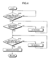
Fig. 4 is a schematic flowchart in a warning control example with respect to a medium ejection operation; -
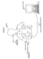
Fig. 5 is a schematic diagram of an overall configuration of a wireless in-vivo information acquiring system according to a second embodiment; -
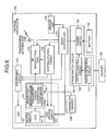
Fig. 6 is a block diagram schematically showing a configuration of a capsule endoscope according to the second embodiment; -
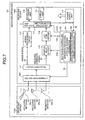
Fig. 7 is a block diagram schematically showing a configuration of a receiving apparatus according to the second embodiment; -
Fig. 8 is a block diagram schematically showing a configuration of a signal processing circuit according to the second embodiment; -
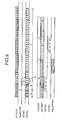
Fig. 9 is a timing chart of a receiving operation of the receiving apparatus according to the second embodiment; -
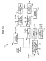
Fig. 10 is a block diagram schematically showing a configuration of a signal processing circuit according to a third embodiment; and -
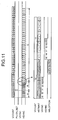
Fig. 11 is a timing chart of a receiving operation of the receiving apparatus according to the third embodiment. -
- 1
- Subject
- 2
- Receiving apparatus
- 3
- Capsule endoscope
- 5
- Portable recording medium
- 23
- LED
- 24
- Display unit
- 25
- Speaker
- Exemplary embodiments of a receiving apparatus according to the present invention will be explained below in detail with reference to the accompanying drawings.
Note that the present invention is not limited to the embodiments, and the embodiments can be variously modified within the range of the scope of the present invention. -
Fig. 1 is a schematic diagram of an overall configuration diagram of a wireless in-vivo information acquiring system according to a first embodiment of the present invention. The wireless in-vivo information acquiring system uses a capsule endoscope as one example of the body-insertable apparatus, which is a transmitting unit. InFig. 1 , the wireless in-vivo information acquiring system includes a receivingapparatus 2 having a radio receiving function, and acapsule endoscope 3 introduced into asubject 1 to take pictures of body cavity images and transmits data such as an image signal to the receivingapparatus 2. The wireless in-vivo information acquiring system also includes adisplay device 4 that displays the body cavity image based on the image signal received by the receivingapparatus 2, and aportable recording medium 5 for transferring data between the receivingapparatus 2 and thedisplay device 4. The receivingapparatus 2 includes anantenna unit 2a including a plurality of receiving antennas A1 to An attached to the body surface of the subject 1, and amain receiving unit 2b as a main receiving apparatus that performs processing of radio signals received via the receiving antennas A1 to An, and these units are detachably connected with each other via a connector or the like. The receiving antennas A1 to An can be equipped on a receiving jacket wearable by the subject, and the subject 1 can carry the receiving antennas A1 to An by wearing the receiving jacket. In this case, the receiving antennas A1 to An can be detachable to the jacket. - The
display device 4 displays the body cavity images and the like taken by thecapsule endoscope 3, and has a configuration of a workstation or the like that displays images based on data acquired by theportable recording medium 5. Specifically, thedisplay device 4 can have a configuration such that images are directly displayed by a CRT display, a liquid crystal display, or the like, or a configuration such that images are output to other media, like a printer. - As the
portable recording medium 5, a CompactFlash® Memory or the like is used, which is detachable relative to themain receiving unit 2b and thedisplay device 4, and has a structure capable of outputting or recording information at the time of being set in both themain receiving unit 2b and thedisplay device 4. In the first embodiment, theportable recording medium 5 is set in thedisplay device 4 of a workstation, for example, before examination, to store identification information such as an examination ID, and immediately before the examination, is set in themain receiving unit 2b and the identification information is read by themain receiving unit 2b and registered in themain receiving unit 2b. While thecapsule endoscope 3 is moving in the body cavity of the subject 1, theportable recording medium 5 is set in themain receiving unit 2b attached to thesubject 1, to record data transmitted from thecapsule endoscope 3. After thecapsule endoscope 3 is discharged from thesubject 1, that is, after imaging of the inside of the subject 1 has finished, theportable recording medium 5 is taken out from themain receiving unit 2b and set in thedisplay device 4, so that thedisplay device 4 reads the data recorded on theportable recording medium 5. For example, since transfer of data between themain receiving unit 2b and thedisplay device 4 is performed by theportable recording medium 5, the subject 1 can freely move during taking pictures of the body cavity, which also contributes to reduction of a transfer period of data between themain receiving unit 2b and thedisplay device 4. - A configuration of the receiving apparatus is explained by using a schematic diagram in
Fig. 2 and a block diagram inFig. 3 . The receivingapparatus 2 has a function for receiving image data of the body cavity wirelessly transmitted from thecapsule endoscope 3. As shown inFigs. 2 and3 , the receivingapparatus 2 has a shape detachable and portable by thesubject 1, and includes theantenna unit 2a and themain receiving unit 2b detachably connected to theantenna unit 2a. Theantenna unit 2a receives the radio signal transmitted from thecapsule endoscope 3 via the receiving antennas A1 to An, demodulates the radio signal to an image signal and outputs the image signal, and themain receiving unit 2b performs signal processing of the image signal. - As shown in
Fig. 2 , acard insertion port 21 for inserting theportable recording medium 5 is formed in a slit shape on the side of themain receiving unit 2b, and acard cover 22 that closes thecard insertion port 21 is provided slidably by aguide member 22a. Therefore, in the first embodiment, theportable recording medium 5 is set in themain receiving unit 2b by sliding thecard cover 22 to open thecard insertion port 21 and inserting theportable recording medium 5 from thecard insertion port 21 to plug in an internal connector. On the other hand, at the time of taking out theportable recording medium 5, theportable recording medium 5 cannot be taken out only by one action, and requires two actions, that is, an operation (action) for sliding and opening thecard cover 22, and an operation (action) for pulling theportable recording medium 5 exposed due to the release of thecard cover 22 out from the card insertion port 21 (or pushing theportable recording medium 5 temporarily). - In the
main receiving unit 2b, anLED 23 is provided near thecard insertion port 21 as a light emission element for the warning unit. Adisplay unit 24 formed of a liquid crystal display, for example, an LCD is provided on the front of themain receiving unit 2b, for example, for displaying registered identification information such as the examination ID. Aspeaker 25 for properly outputting information by speech is provided on the upper front of themain receiving unit 2b. - The
antenna unit 2a includes, as shown inFig. 3 , a changeover switch SW that selectively switches connection any one of the receiving antennas A1 to An, and a receivingcircuit 11 connected to a subsequent stage of the changeover switch SW for amplifying the radio signal from the receiving antennas A1 to An switched by the changeover switch SW, and demodulating the radio signal to the image signal as transmission information. - The
main receiving unit 2b receives the image signal demodulated by theantenna unit 2a to perform signal processing. Themain receiving unit 2b includes asignal processing circuit 13 connected at a subsequent stage of the receivingcircuit 11, an A/D converter 14, astorage unit 15 that stores various pieces of information, theportable recording medium 5, theLED 23, thedisplay unit 24, thespeaker 25, anejection detector 26, a control unit C that controls these respective components, and apower supply unit 16 that supplies power to themain receiving unit 2b and theantenna unit 2a. - The
ejection detector 26 is formed of a mechanical switch or the like to detect the ejection operation of theportable recording medium 5. More specifically, it is configured so as to detect the ejection operation of theportable recording medium 5, during the ejection operation requiring two actions, and at the time of starting an operation for sliding and opening thecard cover 22, which is the first operation. - The
signal processing circuit 13 performs signal processing such as serial/parallel conversion, pixel interpolation processing, and image compression processing, relative to the image signal data demodulated by the receivingcircuit 11 such as theantenna unit 2a. The control unit C includes a switching controller C1 that controls changeover of the antenna, a recording operation detector C2 as an operation detector that detects that the recording operation is in progress, and a warning controller C3 as a control unit that controls whether a warning by lighting or blinking, which indicates that the ejection operation should not be performed, is to be given to the user through theLED 23. - The receiving
circuit 11 amplifies the radio signal output from the changeover switch SW, and outputs a demodulated image signal S1 to thesignal processing circuit 13, and a received strength signal S2 indicating the signal strength of the amplified radio signal to the A/D converter 14. The image data processed by thesignal processing circuit 13 is stored in theportable recording medium 5 by the control unit C, and the image is displayed on thedisplay unit 24 according to need. The received strength signal S2 converted to a digital signal by the A/D converter 14 is fetched by the control unit C. The switching controller C1 selects a receiving antenna having received the data with the largest signal strength as a receiving antenna for acquiring the image data, based on the received strength signal S2 obtained by sequentially switching the receiving antennas A1 to An, and outputs a changeover signal S3 instructing the changeover to the antenna to the changeover switch SW. Further, the control unit C stores the signal strength received by the respective receiving antennas in theportable recording medium 5 together with the image data, in correspondence with the selected receiving antenna. The stored signal strength of the respective receiving antennas becomes the information for calculating the position of thecapsule endoscope 3 in the subject at the time of receiving the image data. - The recording operation detector C2 detects that a recording operation relative to the mounted
portable recording medium 5 is in progress (is under examination). For example, in a stage where after a power supply of themain receiving unit 2b is turned on, a synchronization signal for triggering is not detected from the radio signal transmitted from thecapsule endoscope 3, it is determined to be before starting the recording operation (before starting examination), and once the synchronization signal is detected, it is determined to be after starting the recording operation. Alternatively, since the format of theportable recording medium 5 is initialized before starting the examination, by looking at the write state to theportable recording medium 5, it can be determined to be before starting the recording operation in a stage where the body cavity image data has not yet been written on theportable recording medium 5. Further, one examination using thecapsule endoscope 3 finishes after a certain period of time has passed since the start of recording, for example, after about eight hours, and thecapsule endoscope 3 is discharged outside of the body cavity. Therefore, an elapsed time since the start of a recording operation is monitored, and after the certain period of time has passed, it can be determined that the recording operation has finished. - The warning controller C3 gives a warning to the user by lighting-on or blinking of the
LED 23 before theportable recording medium 5 is ejected from thecard insertion port 21, when the ejection operation of theportable recording medium 5 is detected by theejection detector 26 during the recording operation, to control the operation of theLED 23. - A warning control example with respect to a medium ejection operation executed by the control unit C in the first embodiment is explained, with reference to a schematic flowchart shown in
Fig. 4 . This process is executed in such a state that the power switch of the receiving apparatus 2 (themain receiving unit 2b) is turned on (step S100: Yes). In such a state, it is determined whether the recording operation is in progress by the detection operation of the recording operation detector C2 (step S101). If the recording operation is in progress (step S101: No), theportable recording medium 5 can be freely ejected, and a warning to the user is not required. Therefore, warning by theLED 23 is not performed (step S102). - If the recording operation is in progress (step S101: Yes), it is determined whether the ejection operation of the
portable recording medium 5 has been detected by referring to the detection result by the ejection detector 26 (step S103). When the ejection operation of theportable recording medium 5 has not been detected (step S103: No), it is a normal state, and hence a warning to the user is not required. Therefore, warning by theLED 23 is not performed (step S104). - On the other hand, during the recording operation (step S101: Yes), when the ejection operation of the
portable recording medium 5 has been detected (step S103: Yes), it is an abnormal state, and hence theLED 23 is controlled so as to be lighted on or blinked, thereby giving a warning to the user so as not to perform the ejection operation of the portable recording medium 5 (step S105). - By giving such a warning, it can be prevented beforehand that the
portable recording medium 5 is erroneously ejected during the recording operation, and hence the body cavity image data can be prevented from being lost and the portable recording medium can be prevented from being damaged. Particularly in the present embodiment, two actions are required for ejecting theportable recording medium 5, and the ejection operation is detected at the time of starting the opening operation of thecard cover 22, which is the first operation, and at this point in time, a warning so as not to perform the ejection operation is generated before theportable recording medium 5 is pulled out from the connector. Accordingly, theportable recording medium 5 can be prevented beforehand from being detached from the connector during the recording operation. In addition, since the warning is generated by theLED 23 provided near thecard insertion port 21, from which theportable recording medium 5 is ejected, a warning so as not to perform ejection can be given to the user effectively. - While in the first embodiment, a warning is generated by lighting-on or blinking of the
LED 23, a warning message, such as "Recording in progress. Do not eject the card.", can be displayed on thedisplay unit 24. Alternatively, a warning sound for stopping the user to eject the card can be issued via thespeaker 25. - In the first embodiment, further, ejection of the
portable recording medium 5 requires two actions (operations or actions), that is, an operation for opening thecard cover 22, and an operation for pulling out theportable recording medium 5. However, the actions are not limited thereto, and for example, two actions can include the opening operation of the card cover and a pressing operation of an eject bar, or two actions can include a lock release operation and the operation for pulling out theportable recording medium 5. - The wireless in-vivo information acquiring system corresponds to a transmitting/receiving system, and the capsule endoscope is used as one example of a transmission apparatus (body-insertable apparatus).
-
Fig. 5 is a schematic diagram of an overall configuration of the wireless in-vivo information acquiring system. As shown inFig. 5 , the wireless in-vivo information acquiring system includes a receivingapparatus 102 having a radio receiving function, and a capsule endoscope (body-insertable apparatus) 103 introduced into the body of a subject 101 to take pictures of the body cavity and perform wireless data transmission of image signals and the like with respect to the receivingapparatus 102. The in-vivo information acquiring system further includes adisplay device 104 that displays the body cavity image based on the image signal received by the receivingapparatus 102, and aportable recording medium 105 that performs data transfer between the receivingapparatus 102 and thedisplay device 104. The receivingapparatus 102 includes a receivingjacket 102a worn by the subject 101 and anexternal device 102b that performs processing of the radio signal received via the receivingjacket 102a. - The
display device 104 displays the body cavity image taken by thecapsule endoscope 103, and has a configuration of a workstation or the like that displays images based on the data acquired by theportable recording medium 105. Specifically, thedisplay device 104 can have a configuration of directly displaying images by a CRT display, a liquid crystal display, or the like, or a configuration of outputting images to other media like a printer. - The
portable recording medium 105 has a configuration detachable to theexternal device 102b and thedisplay device 104, and capable of outputting or recording information when theportable recording medium 105 is set in theexternal device 102b and thedisplay device 104. Specifically, theportable recording medium 105 is set in theexternal device 102b to record data transmitted from thecapsule endoscope 103, when thecapsule endoscope 103 is moving in the body cavity. When thecapsule endoscope 103 is discharged from the subject 101, that is, when imaging of the inside of the subject 101 has finished, theportable recording medium 105 is taken out from theexternal device 102b and set in thedisplay device 104, and the recorded data is read by thedisplay device 104. By performing data transfer between theexternal device 102b and thedisplay device 104 by theportable recording medium 105 such as a CompactFlash® Memory or the like, the subject 101 can freely move during imaging of the body cavity, than in a case when theexternal device 102b and thedisplay device 104 are connected with each other by wire, which further contributes to reduction of the data transfer time between theexternal device 102b and thedisplay device 104. Here, theportable recording medium 105 is used for the data transfer between theexternal device 102b and thedisplay device 104. However, the present invention is not limited thereto, and another built-in recording device can be used for theexternal device 102b, and the built-in recording device can be connected to thedisplay device 104 by wire or wireless connection for the data transfer. - Here, the
capsule endoscope 103 is explained.Fig. 6 is a block diagram schematically showing a configuration of thecapsule endoscope 103. Thecapsule endoscope 103 includes anLED 119 for irradiating an imaging area at the time of imaging the inside of the subject 101, anLED driving circuit 120 that controls driving state of theLED 119, aCCD 121 as an imaging device that images the area irradiated by theLED 119, and a signal processing circuit 1122 that processes the image signal output from theCCD 121 to imaging information in a desired shape. Thecapsule endoscope 103 further includes aCCD driving circuit 125 that controls driving state of theCCD 121, anRF transmitting unit 123 that generates an RF signal by modulating the image data imaged by theCCD 121 and processed by the signal processing circuit 1122, atransmission antenna unit 124 that transmits an RF signal output from theRF transmitting unit 123, and asystem control circuit 126 that controls an operation of theLED driving circuit 120, theCCD driving circuit 125, and theRF transmitting unit 123. TheCCD 121, the signal processing circuit 1122, and theCCD driving circuit 125 are collectively referred to as animaging circuit 127. - By having these mechanisms, the
capsule endoscope 103 acquires image information of a region to be examined irradiated by theLED 119 by theCCD 121, while thecapsule endoscope 103 is introduced in the subject 101. The acquired image information is subjected to signal processing and converted to an image signal by the signal processing circuit 1122, and the image signal is converted to an RF signal in theRF transmitting unit 123, and transmitted to the outside via thetransmission antenna unit 124. - The signal processing circuit 1122 includes a parameter/error-correcting
code adder 122a. The parameter/error-correctingcode adder 122a adds white balance factor data "WB" as parameter information specific to thecapsule endoscope 103 stored beforehand in aparameter memory 128; ID information "ID" specific to the capsule; and Reed-Solomon codes "RS1" and "RS2" as error-correcting code data respectively for the white balance factor data "WB" and the ID information "ID" specific to the capsule, so that these data are transmitted at a predetermined arrangement position specified beforehand so as to be synchronized with a vertical synchronization signal and a horizontal synchronization signal of the image signal in one frame. - In other words, in the second embodiment, the
capsule endoscope 103 transmits a radio signal having a frame configuration including at least main information that includes information main part based on the image signal acquired by imaging, and an added portion that includes synchronization information, the white balance factor data "WB" as the parameter information specific to thecapsule endoscope 103, and the ID information "ID" specific to the capsule. The Reed-Solomon codes "RS1" and "RS2" are added immediately after the white balance factor data "WB" and the ID information "ID" specific to the capsule. - With reference to
Fig. 9 indicating a timing chart of the receiving operation of the receivingapparatus 102, a 16-bit code of "55 00FF 55" is used as a code indicating the vertical synchronization signal VSYNC (VD), and the 16-bit code is allocated to particular line positions specified by "352", "353", "354", and "355" as count values HCOUNT of the horizontal synchronization signal in a phase having a count value VCOUNT of "10" since start of the operation, and transmitted. Further, a 16-bit code of "55AA FF 55" is used as a code indicating the horizontal synchronization signal HSYNC (HV), and the 16-bit code is allocated to particular line positions specified by "2", "3", "4", and "5" as count values HCOUNT of the horizontal synchronization signal in a phase having a count value VCOUNT of "11" since start of the operation, and transmitted. The white balance factor data "WB", the ID information "ID" specific to the capsule, and the Reed-Solomon codes "RS1" and "RS2" are data, for example, of 1 byte respectively, and in total, 4-byte data, and are set so that these data are respectively allocated to the particular line positions specified by "357", "358", "359", and "360" as count values HCOUNT of the horizontal synchronization signal in the phase having a count value VCOUNT of "10", between the code indicating the vertical synchronization signal VSYNC (VD) and the code indicating the horizontal synchronization signal HSYNC (HV), and transmitted. InFig. 9 , a period A indicates a waiting time until a receivingcircuit 111 of the receivingapparatus 102 is turned on and stabilized, a period B indicates a waiting time until an PLL circuit in aclock recovery 161 is turned on and locked, and a period C indicates a receiving period of the image signal. - The white balance factor data "WB" is data for performing white balance processing with respect to imaged data by the
CCD 121, and is obtained as a white balance factor specific to theCCD 121 beforehand by a test in a manufacturing process of therespective capsule endoscopes 103. Specifically, a white chart as a reference is imaged by theCCD 121, and a correction factor (white balance factor) is calculated so that outputs of red (R) and blue (B) become specified values, using green (G) as a reference, and stored in theparameter memory 128. - The specific parameter information is not limited to the data of the white balance factor, and for example, can be data indicating an address of a pixel defect of the
CCD 121, and can be used for correcting the pixel defect present at the address based on pixel data corresponding to a peripheral address of the address of the pixel defect. Further, an offset value of a photoelectric transfer characteristic, which is a value specific to each CMOS sensor, for example, when the CMOS sensor is used as the imaging device instead of the CCD, can be stored beforehand in theparameter memory 128 as a parameter for the signal processing specific to each device. - The ID information "ID" specific to the capsule is identification number data added beforehand for each
capsule endoscope 103 to determine thecapsule endoscope 103 individually, and stored in theparameter memory 128 beforehand. - The Reed-Solomon codes "RS1" and "RS2" are codes calculated as error-correcting codes relative to the already calculated and set white balance factor data "WB" and ID information "ID" specific to the capsule, and stored in the
parameter memory 128 beforehand. The error-correcting codes need not always be the Reed-Solomon codes, and other codes, for example, Hamming codes can be used. - The
capsule endoscope 103 includes asensor unit 135 that detects predetermined signals such as magnetic, optical, or radio signals, and adrive controller 134 that controls drive of thesystem control circuit 126 that performs overall control of processing of theLED driving circuit 120, theCCD driving circuit 125, theRF transmitting unit 123, and respective units, based on a value detected by thesensor unit 135. Thesensor unit 135 is achieved by, for example, a pH sensor, and detects whether thecapsule endoscope 103 has reached a predetermined position in the subject, and thedrive controller 134 controls the drive of respective units based on the result. Accordingly, power consumption can be reduced. - The
drive controller 134 is supplied with power from abattery 140 as an energy source via apower switch 133 in apower switch circuit 130. Thebattery 140 is achieved, for example, by a button battery such as silver oxide. Thepower switch 133 is a main power switch of thecapsule endoscope 103. Thepower switch circuit 130 has asignal detection circuit 131 and aswitch control circuit 132. Thesignal detection circuit 131 that detects a signal from the outside of thecapsule endoscope 103 is achieved by a reed switch, and is turned on or off when amagnet 150 approaches to or is separated from the reed switch. That is, theswitch control circuit 132 that performs an on or off operation based on whether a magnetic force acts on the reed switch controls such that on/off of thepower switch 133 is toggled based on the control signal from thesignal detection circuit 131, that is, the on/off signal. The on/off of thepower switch 133 by themagnet 150 is performed before thecapsule endoscope 103 is introduced into the subject 101, to check the operation of thecapsule endoscope 103. - The receiving
apparatus 102 is explained with reference toFig. 7 . The receivingapparatus 102 has a function for receiving body cavity image data wirelessly transmitted from thecapsule endoscope 103.Fig. 7 is a block diagram schematically showing a configuration of the receiving apparatus. As shown inFig. 7 , the receivingapparatus 102 has a shape wearable by the subject 101, and includes the receivingjacket 102a having receiving antennas A1 to An, and theexternal device 102b that processes the received radio signals. Each of the receiving antennas A1 to An can be equipped on the receivingjacket 102a so as to be directly adhered on the body surface of the subject, and can be detachable from the receivingjacket 102a. - The
external device 102b has a function for processing the radio signals transmitted from thecapsule endoscope 103. Specifically, theexternal device 102b includes a changeover switch SW that switches connection of the receiving antennas A1 to An, the receivingcircuit 111 connected to a subsequent stage of the changeover switch SW for amplifying and demodulating the radio signal from the receiving antennas A1 to An switched by the changeover switch SW. Asignal processing circuit 112 and a sample-hold circuit 115 are connected to a subsequent stage of the receivingcircuit 111. An A/D converter 116 is further connected to a subsequent stage of a sample-hold circuit 115. The control unit C has a selection controller C1, which connects astorage unit 113, adisplay unit 114, and a switching controller SC corresponding to thesignal processing circuit 112, the A/D converter 116, and theportable recording medium 105 to each other. The switching controller SC has strength-receiving-antenna number information N1 and image-receiving-antenna number information N2, generates a changeover instruction of the changeover switch SW based on these pieces of number information, and instructs a processing timing of the sample-hold circuit 115, the A/D converter 116, and the selection controller C1. Apower supply unit 117 supplies power to respective units, and is achieved by a battery, for example. - The changeover switch SW in the
external device 102b selectively switches any one of the receiving antennas A1 to An based on the switching instruction from the switching controller SC, and outputs a radio signal from the switched antenna of the receiving antennas A1 to An to the receivingcircuit 111. - The receiving
circuit 111 outputs an image signal S1 obtained by amplifying and demodulating the radio signal to thesignal processing circuit 112, and outputs a received strength signal S2, which is a received electric-field strength of the amplified radio signal, to the sample-hold circuit 115. The image data processed by thesignal processing circuit 112 is stored in thestorage unit 113 by the control unit C, and displayed by thedisplay unit 114. The signal sample-held by the sample-hold circuit 115 is converted to a digital signal by the A/D converter 116, and fetched by the control unit C. The selection controller C1 in the control unit C selects a receiving antenna, which has received the largest received electric-field strength of the electric-field strength received during a part of the synchronization period and a horizontal blanking period in the image signal period as a receiving antenna in the image signal period. Further, the selection controller C1 sequentially selects a receiving antenna other than the selected receiving antenna as the receiving antenna during a part of the synchronization period and the horizontal blanking period in the image signal period, and outputs a signal S4, in which the respective receiving antenna numbers are designated as strength-receiving-antenna number information N1 and image-receiving-antenna number information N2, to the switching controller SC. The control unit C stores the received electric-field strength during a part of the synchronization period and the horizontal blanking period in the image signal period and the received electric-field strength during an image receiving period excluding at least the horizontal blanking period in thestorage unit 113 in correspondence with the receiving antenna selected at that time, together with the image data. The stored received electric-field strength of respective receiving antennas becomes information for calculating the position of thecapsule endoscope 103 in the subject when the image data is received. - The switching controller SC holds the strength-receiving-antenna number information N1 and the image-receiving-antenna number information N2 instructed by the selection controller C1, and instructs the changeover switch SW so as to selectively connect any one of the receiving antennas A1 to An corresponding to the strength-receiving-antenna number information N1 during a part of the synchronization period and the horizontal blanking period in the image signal period. Further, the switching controller SC outputs a signal S5 instructing the changeover switch SW so as to selectively connect any one of the receiving antennas A1 to An corresponding to the image-receiving-antenna number information N2 during the image receiving period excluding at least the horizontal blanking period, to the changeover switch SW, and outputs a signal S3a instructing a sample-hold timing by the sample-
hold circuit 115, a signal S3b instructing an A/D conversion timing by the A/D converter 116, and a signal S3c instructing a selection control by the selection controller C1. - The
signal processing circuit 112 is explained with reference toFig. 8 . Thesignal processing circuit 112 has a function for performing predetermined processing with respect to the body cavity image data wirelessly transmitted from thecapsule endoscope 103 and received, and storing the body cavity image data in the storage unit 113 (the portable recording medium 105) after subjecting the image data to compression processing and the like.Fig. 8 is a block diagram schematically showing a configuration of thesignal processing circuit 112. - As shown in
Fig. 8 , thesignal processing circuit 112 includes theclock recovery 161 to which the image signal from the receivingapparatus 11 is input, an S/P converter 162, asynchronization detector 163, animage generator 164 connected to the output side of the S/P converter 162, a WB/ID position detector 165, aframe memory 166 connected to the output side of theimage generator 164, anerror correcting unit 167 connected to the output side of the WB/ID position detector 165, and animage processor 168 connected to theframe memory 166 and theerror correcting unit 167 to output a processing result to the control unit C. - The
clock recovery 161 includes a PLL circuit and the like, reproduces the clock based on the image signal S1, and outputs the clock to the WB/ID position detector 165 and the like. The S/P converter 162 converts the base-band image signal S1 input as a serial signal to a parallel signal, synchronized with the clock. Thesynchronization detector 163 monitors the data of the input image signal S1, and outputs a pulse of the vertical synchronization signal VD to theimage generator 164 and the WB/ID position detector 165, upon detection of, for example, the code "55 00FF 55". Upon detection of, for example, the code "55AA FF 55", thesynchronization detector 163 outputs a pulse of the horizontal synchronization signal HD to theimage generator 164. Theimage generator 164 generates frame image data by performing the image generation processing with respect to the parallel-converted image signal at a timing synchronized with the vertical synchronization signal VD and the horizontal synchronization signal HD, and temporarily stores the frame image data in theframe memory 166. - On the other hand, the WB/
ID position detector 165 monitors the count value HCOUNT of the horizontal synchronization signal based on the vertical synchronization signal VD, detects whether the count value HCOUNT has reached the count values HCOUNT "357" and "358" as the positions where the white balance factor data "WB" and the ID information "ID" specific to the capsule are arranged, and when the count values have reached the count values HCOUNT "357" and "358", receives 4-byte data including the Reed-Solomon codes "RS1" and "RS2" immediately thereafter. Theerror correcting unit 167 performs error correction with respect to the white balance factor data "WB" and the ID information "ID" specific to the capsule by the Reed-Solomon codes "RS1" and "RS2" by using the received 4-byte data, to output the error-corrected right white balance factor data "WB" and ID information "ID" specific to the capsule to theimage processor 168. In other words, in the second embodiment, after having detected the code "55 00FF 55" indicating the vertical synchronization signal VD, the WB/ID position detector 165 counts the horizontal synchronization signal HCOUNT, specifies the positions of white balance factor data "WB" and the ID information "ID" specific to the capsule, and performs error correction by the Reed-Solomon codes "RS1" and "RS2" added immediately thereafter. - The
image processor 168 uses the error-corrected white balance factor data "WB" to perform white balance processing and required image processing such as compression processing, with respect to the frame image data generated and temporarily stored in theframe memory 166, and stores the data in the storage unit 113 (the portable recording medium 105) under control of the control unit C. At the time of such image processing, theimage processor 168 checks the error-corrected ID information "ID" specific to the capsule, and when the ID information "ID" does not agree with the ID information "ID" specific to the capsule in the previous frame, determines that the image data is transmitted from anothercapsule endoscope 103, so that the image data is not stored in the storage unit 113 (the portable recording medium 105). - Thus, in the second embodiment, the Reed-Solomon codes "RS1" and "RS2" are added to the white balance factor information "WB" specific to the
capsule endoscope 103 and the ID information "ID" specific to the capsule for deciding thecapsule endoscope 103 and transmitted. On the receivingapparatus 102 side, the Reed-Solomon codes "RS1" and "RS2" are used to perform error correction of the white balance factor information "WB" and the ID information "ID" specific to the capsule. Accordingly, even if a bit error such as data garbling occurs in the white balance factor information "WB" and the ID information "ID" specific to the capsule, the information can be corrected to right data by the error correction processing. Particularly, according to the Reed-Solomon codes, data garbling of one byte can be also corrected, which has higher reliability than the Hamming code for correcting one bit. Therefore, tolerance against a bit error in the parameter information such as the white balance factor information "WB" can be increased, and the number of invalidated image signals can be reduced as much as possible in a unit of frame. Further, since the error-correcting codes are added only to the important parameter information such as the white balance factor information "WB" and the ID information "ID" specific to the capsule, and are not added to the image signal itself, which is a greater part of data, redundancy of data can be reduced to the necessity minimum. - In the transfer operation of the radio signal between the
capsule endoscope 103 and the receivingapparatus 102, synchronization cannot be achieved correctly, if there is one bit error relating to the code "55 00FF 55" indicating the vertical synchronization signal VD or the code "55AA FF 55" indicating the horizontal synchronization signal HD, of 16-bit configuration respectively. Specifically, the code "55 00FF 55" indicating the vertical synchronization signal VD has a particular relation with the arrangement position of the white balance factor information "WB" and the ID information "ID" specific to the capsule. Therefore, when the vertical synchronization signal VD cannot be correctly detected, the arrangement position of the white balance factor data "WB", the ID information "ID" specific to the capsule cannot be detected correctly. Further, if the code "55AA FF 55" indicating the horizontal synchronization signal HD cannot be detected due to a bit error, the line synchronization of the image signal cannot be achieved reliably. - In the third embodiment, therefore, the error-correcting code is added only to the important parameter information such as the white balance factor information "WB" and the ID information "ID" specific to the capsule. However, in the third embodiment, the error-correcting code is also added to the code "55 00
FF 55" indicating the vertical synchronization signal VD and the code "55AA FF 55" indicating the horizontal synchronization signal HD. - The parameter/error-correcting
code adder 122a in the third embodiment adds Reed-Solomon codes "RS3", "RS4", "RS5", and "RS6" one bit each as the error-correcting code stored beforehand in theparameter memory 128 immediately after the code "55 00FF 55" indicating the vertical synchronization signal VD and the code "55AA FF 55" indicating the horizontal synchronization signal HD transmitted in a specified predetermined arrangement relation. - With reference to
Fig. 11 , which shows a timing chart of a receiving operation of the receivingapparatus 102 in the third embodiment, the 16-bit code of "55 00FF 55" is used as the code indicating the vertical synchronization signal VSYNC (VD), and the vertical synchronization signal VSYNC (VD) is set so as to be allocated to particular line positions specified by "350", "351", "352", and "353" as count values HCOUNT of the horizontal synchronization signal in the phase having the count value VCOUNT of "10" since start of the operation, and transmitted, and the Reed-Solomon codes "RS3", and "RS4" for error correction are set so as to be allocated to particular line positions specified by "354" and "355" as count values HCOUNT immediately thereafter, and transmitted. - Further, the 16-bit code of "55
AA FF 55" is used as the code indicating the horizontal synchronization signal HSYNC (HV), and the horizontal synchronization signal HSYNC (HV) is set so as to be allocated to particular line positions specified by "0", "1", "2", and "3" as count values HCOUNT of the horizontal synchronization signal in the phase having the count value VCOUNT of "11" since start of the operation, and transmitted, and the Reed-Solomon codes "RS5", and "RS6" for error correction are set so as to be allocated to particular line positions specified by "4" and "5" as count values HCOUNT immediately thereafter, and transmitted. - A
signal processing circuit 170 in the third embodiment is explained with reference toFig. 10. Fig. 10 is a block diagram schematically showing a configuration of thesignal processing circuit 170. Thesignal processing circuit 170 includes a synchronization-code-position detectingshift register 171, anerror correcting unit 172, and acode comparator 173, in addition to the configuration of thesignal processing circuit 112. - The synchronization-code-position detecting
shift register 171 detects whether the count values VCOUNT and HCOUNT have reached the count value VCOUNT "10" and the count values HCOUNT "350" to "353" where the code indicating the vertical synchronization signal VD should be present, while shifting the image signal S1 input corresponding to the clock, and when the count values have reached these positions, receives 6-byte data including the Reed-Solomon codes "RS3" and "RS4" immediately thereafter. Theerror correcting unit 172 performs error correction with respect to a code indicating the vertical synchronization signal VD by the Reed-Solomon codes "RS3" and "RS4" by using the received 6-byte data. Thecode comparator 173 compares and determines whether the error-corrected code indicating the vertical synchronization signal VD agrees with the code "55 00FF 55" indicating the original vertical synchronization signal VD. When these codes agrees with each other, thecode comparator 173 determines that the code has been detected correctly and outputs a pulse of the vertical synchronization signal VD to theimage generator 164 and the WB/ID position detector 165. Accordingly, even if there is a bit error in the code indicating the vertical synchronization signal VD, the correct vertical synchronization signal VD can be detected, and the arrangement position of the white balance factor information "WB" and the ID information "ID" specific to the capsule can be correctly detected. The code comparator 73 also outputs the vertical synchronization signal VD to the synchronization-code-position detectingshift register 171, and resets the counter. - Further, the synchronization-code-position detecting
shift register 171 detects whether the count values VCOUNT and HCOUNT have reached the count value VCOUNT "11" and the count values HCOUNT "0" to "3" where the code indicating the horizontal synchronization signal HD should be present, while shifting the image signal S1 input corresponding to the clock, and when the count values have reached these positions, receives 6-byte data including the Reed-Solomon codes "RS5" and "RS8" immediately thereafter. Theerror correcting unit 172 performs error correction with respect to a code indicating the horizontal synchronization signal HD by the Reed-Solomon codes "RS5" and "RS6" by using the received 6-byte data. Thecode comparator 173 compares and determines whether the error-corrected code indicating the horizontal synchronization signal VD agrees with the code "55AA FF 55" indicating the original horizontal synchronization signal HD. When these codes agree with each other, thecode comparator 173 determines that the code has been detected correctly and outputs a pulse of the horizontal synchronization signal HD to theimage generator 164. Accordingly, even if there is a bit error in the code indicating the horizontal synchronization signal HD, the correct horizontal synchronization signal HD can be detected, and the line synchronization can be achieved reliably. Thecode comparator 173 also outputs the horizontal synchronization signal HD to the synchronization-code-position detectingshift register 171, and resets the counter. - The first to the third embodiments described in this specification can be embodied by combining each other.
- The receiving apparatus according to the present invention is useful at the time of receiving a radio signal transmitted from the body-insertable apparatus such as the capsule endoscope and recording the radio signal on a portable recording medium detachably attached thereto. Particularly, the receiving apparatus is suitable for preventing erroneous operations when the portable recording medium can be ejected even during the examination.
Claims (6)
- A receiving apparatus that receives a radio signal transmitted from a body-insertable apparatus introduced into a subject, and records the radio signal on a portable recording medium detachably attached thereto, the receiving apparatus comprising:an in-operation detector that detects that a recording operation is in progress;an ejection operation detector that detects an ejection operation of the portable recording medium;a warning unit that gives a warning to a user; anda control unit that operates the warning unit before the portable recording medium is ejected, when the ejection operation of the portable recording medium is detected during the recording operation.
- The receiving apparatus according to claim 1, wherein the portable recording medium is detachably attached by a plurality of operations or actions, and
the ejection operation detector detects the ejection operation of the portable recording medium, at the time of starting the first one of the plurality of operations or actions. - The receiving apparatus according to claim 1 or 2, wherein the warning unit generates a warning by a warning display on a display unit.
- The receiving apparatus according to claim 1 or 2, wherein the warning unit generates a warning by lighting-on or blinking of a light emission element.
- The receiving apparatus according to claim 4, wherein the light emission element is provided near an ejector of the portable recording medium.
- The receiving apparatus according to claim 1 or 2, wherein the warning unit generates a warning by a warning sound.
Applications Claiming Priority (3)
| Application Number | Priority Date | Filing Date | Title |
|---|---|---|---|
| JP2005248011A JP4855738B2 (en) | 2005-08-29 | 2005-08-29 | Receiver |
| JP2005265704A JP4823621B2 (en) | 2005-09-13 | 2005-09-13 | Receiving device, transmitting device, and transmitting / receiving system |
| PCT/JP2006/317008 WO2007026713A1 (en) | 2005-08-29 | 2006-08-29 | Receiver apparatus |
Publications (2)
| Publication Number | Publication Date |
|---|---|
| EP1920704A1 true EP1920704A1 (en) | 2008-05-14 |
| EP1920704A4 EP1920704A4 (en) | 2010-11-03 |
Family
ID=37808800
Family Applications (1)
| Application Number | Title | Priority Date | Filing Date |
|---|---|---|---|
| EP06796985A Withdrawn EP1920704A4 (en) | 2005-08-29 | 2006-08-29 | Receiver apparatus |
Country Status (4)
| Country | Link |
|---|---|
| US (2) | US20090076352A1 (en) |
| EP (1) | EP1920704A4 (en) |
| AU (1) | AU2006285874B2 (en) |
| WO (1) | WO2007026713A1 (en) |
Families Citing this family (12)
| Publication number | Priority date | Publication date | Assignee | Title |
|---|---|---|---|---|
| US9007478B2 (en) | 2007-01-09 | 2015-04-14 | Capso Vision, Inc. | Methods to compensate manufacturing variations and design imperfections in a capsule camera |
| US8405711B2 (en) * | 2007-01-09 | 2013-03-26 | Capso Vision, Inc. | Methods to compensate manufacturing variations and design imperfections in a capsule camera |
| US10499029B2 (en) | 2007-01-09 | 2019-12-03 | Capso Vision Inc | Methods to compensate manufacturing variations and design imperfections in a display device |
| JP4918438B2 (en) * | 2007-08-31 | 2012-04-18 | オリンパスメディカルシステムズ株式会社 | In-subject information acquisition system |
| US8599824B2 (en) * | 2008-01-11 | 2013-12-03 | Broadcom Corporation | Method and system for bluetooth conditional synchronization |
| WO2012042987A1 (en) * | 2010-09-28 | 2012-04-05 | オリンパスメディカルシステムズ株式会社 | Image display device and capsule endoscope system |
| JP2012081016A (en) * | 2010-10-08 | 2012-04-26 | Olympus Corp | Biological information acquisition device |
| JP5734614B2 (en) * | 2010-10-08 | 2015-06-17 | オリンパス株式会社 | Biological information acquisition device |
| EP2647329A4 (en) * | 2010-11-29 | 2016-01-13 | Olympus Corp | Reception device and capsule-type endoscope system |
| JP2013009056A (en) * | 2011-06-22 | 2013-01-10 | Toshiba Corp | Semiconductor device and method of setting parameter thereof |
| US11607120B2 (en) * | 2018-04-09 | 2023-03-21 | Electronics And Telecommunications Research Institute | Capsule endoscopic receiving device, capsule endoscope system including the same, and operating method of capsule endoscopic receiving device |
| CN113271836A (en) * | 2019-01-11 | 2021-08-17 | 奥林巴斯株式会社 | Capsule endoscope system and receiving apparatus |
Family Cites Families (24)
| Publication number | Priority date | Publication date | Assignee | Title |
|---|---|---|---|---|
| JPH04205691A (en) * | 1990-11-30 | 1992-07-27 | Toshiba Corp | Portable electronic device |
| JPH06225273A (en) | 1993-01-25 | 1994-08-12 | Matsushita Electric Ind Co Ltd | Error correction device |
| US6571361B1 (en) * | 1995-09-29 | 2003-05-27 | Kabushiki Kaisha Toshiba | Encoder and decoder |
| JPH10285526A (en) * | 1997-04-03 | 1998-10-23 | Konica Corp | Digital still camera |
| JP2000067182A (en) * | 1998-08-24 | 2000-03-03 | Nec Corp | Card removal prevention method and card removal prevention device |
| JP4454832B2 (en) | 1999-11-22 | 2010-04-21 | オリンパス株式会社 | Electronics |
| US6470049B1 (en) * | 2000-05-31 | 2002-10-22 | Next Level Communications, Inc. | Method for dealing with missing or untimely synchronization signals in digital communications systems |
| US6738671B2 (en) * | 2000-10-26 | 2004-05-18 | Medtronic, Inc. | Externally worn transceiver for use with an implantable medical device |
| US6975752B2 (en) * | 2001-01-31 | 2005-12-13 | General Electric Company | Imaging system including detector framing node |
| JP4154129B2 (en) | 2001-02-16 | 2008-09-24 | 株式会社リコー | Digital still camera |
| US20020163971A1 (en) | 2001-02-23 | 2002-11-07 | Goran Roth | Video bitstream washer |
| JP2002330384A (en) | 2001-04-27 | 2002-11-15 | Canon Inc | Warning device, warning device for digital camera, control method therefor, and medium providing control program |
| IL143260A (en) | 2001-05-20 | 2006-09-05 | Given Imaging Ltd | Array system and method for locating an in vivo signal source |
| JP4009939B2 (en) * | 2002-02-22 | 2007-11-21 | 株式会社ジーエス・ユアサコーポレーション | Electric hydraulic tool |
| JP4276811B2 (en) * | 2002-02-26 | 2009-06-10 | オリンパス株式会社 | Image recording device |
| JP2004037239A (en) * | 2002-07-03 | 2004-02-05 | Fuji Heavy Ind Ltd | Method and apparatus for determining same object, and method and apparatus for correcting displacement |
| JP4022874B2 (en) | 2002-11-22 | 2007-12-19 | 富士フイルム株式会社 | Electronics |
| WO2004100776A1 (en) * | 2003-05-14 | 2004-11-25 | Olympus Corporation | Capsule medical device |
| JP4574983B2 (en) | 2003-11-04 | 2010-11-04 | オリンパス株式会社 | Image display apparatus, image display method, and image display program |
| JP4503987B2 (en) | 2003-11-12 | 2010-07-14 | オリンパス株式会社 | Capsule endoscope |
| JP2005192632A (en) * | 2003-12-26 | 2005-07-21 | Olympus Corp | Subject interior moving state detecting system |
| US7370932B2 (en) * | 2004-05-27 | 2008-05-13 | Silverbrook Research Pty Ltd | Cartridge having integrated circuit for enabling validation thereof by a mobile device |
| JP4205691B2 (en) | 2005-04-11 | 2009-01-07 | 株式会社モリタ製作所 | Medical X-ray equipment |
| JP4816140B2 (en) * | 2006-02-28 | 2011-11-16 | ソニー株式会社 | Image processing system and method, image processing apparatus and method, imaging apparatus and method, program recording medium, and program |
-
2006
- 2006-08-29 US US11/576,512 patent/US20090076352A1/en not_active Abandoned
- 2006-08-29 EP EP06796985A patent/EP1920704A4/en not_active Withdrawn
- 2006-08-29 WO PCT/JP2006/317008 patent/WO2007026713A1/en not_active Ceased
- 2006-08-29 AU AU2006285874A patent/AU2006285874B2/en not_active Ceased
-
2011
- 2011-06-21 US US13/165,513 patent/US8732546B2/en not_active Expired - Fee Related
Also Published As
| Publication number | Publication date |
|---|---|
| US20090076352A1 (en) | 2009-03-19 |
| US8732546B2 (en) | 2014-05-20 |
| AU2006285874A1 (en) | 2007-03-08 |
| WO2007026713A1 (en) | 2007-03-08 |
| US20110252291A1 (en) | 2011-10-13 |
| AU2006285874B2 (en) | 2009-10-29 |
| EP1920704A4 (en) | 2010-11-03 |
Similar Documents
| Publication | Publication Date | Title |
|---|---|---|
| US8732546B2 (en) | Radio receiver with an error correction code detector and with a correction unit | |
| JP4530931B2 (en) | Imaging display system and in-subject indwelling system | |
| EP2011430B1 (en) | Antenna unit and receiving system | |
| CN101790343B (en) | In vivo information acquisition system | |
| AU2005283435B2 (en) | Capsule-type endoscope | |
| JP4847075B2 (en) | Receiver | |
| CN100441138C (en) | receiving device | |
| JP4767631B2 (en) | Receiver | |
| JP2005192819A (en) | Receiver | |
| CN100579441C (en) | Receiving device and receiving system | |
| JP4398414B2 (en) | Receiver | |
| JP4855738B2 (en) | Receiver | |
| JP4823621B2 (en) | Receiving device, transmitting device, and transmitting / receiving system | |
| JP4663279B2 (en) | Reception device, medical device, and identification information generation registration method | |
| JP4445806B2 (en) | Receiver | |
| JP4009610B2 (en) | Receiver | |
| JP2006026299A (en) | Receiving device | |
| CN1937950A (en) | Receiver | |
| JP2005319095A (en) | Receiver | |
| JP2005277740A (en) | Receiver | |
| JP2006320649A (en) | Receiving apparatus and receiving system | |
| JP2005223427A (en) | Receiver | |
| JP2006043109A (en) | Receiver and medical device |
Legal Events
| Date | Code | Title | Description |
|---|---|---|---|
| PUAI | Public reference made under article 153(3) epc to a published international application that has entered the european phase |
Free format text: ORIGINAL CODE: 0009012 |
|
| 17P | Request for examination filed |
Effective date: 20080211 |
|
| AK | Designated contracting states |
Kind code of ref document: A1 Designated state(s): DE FR GB |
|
| DAX | Request for extension of the european patent (deleted) | ||
| RBV | Designated contracting states (corrected) |
Designated state(s): DE FR GB |
|
| A4 | Supplementary search report drawn up and despatched |
Effective date: 20101006 |
|
| 17Q | First examination report despatched |
Effective date: 20110609 |
|
| STAA | Information on the status of an ep patent application or granted ep patent |
Free format text: STATUS: THE APPLICATION IS DEEMED TO BE WITHDRAWN |
|
| 18D | Application deemed to be withdrawn |
Effective date: 20111020 |