EP1920232B1 - System for detection and analysis of biological waste spread in an undergarment - Google Patents
System for detection and analysis of biological waste spread in an undergarment Download PDFInfo
- Publication number
- EP1920232B1 EP1920232B1 EP06758508A EP06758508A EP1920232B1 EP 1920232 B1 EP1920232 B1 EP 1920232B1 EP 06758508 A EP06758508 A EP 06758508A EP 06758508 A EP06758508 A EP 06758508A EP 1920232 B1 EP1920232 B1 EP 1920232B1
- Authority
- EP
- European Patent Office
- Prior art keywords
- mannequin
- sensors
- excretory product
- undergarment
- photodiode
- Prior art date
- Legal status (The legal status is an assumption and is not a legal conclusion. Google has not performed a legal analysis and makes no representation as to the accuracy of the status listed.)
- Expired - Lifetime
Links
Images




Classifications
-
- G—PHYSICS
- G01—MEASURING; TESTING
- G01N—INVESTIGATING OR ANALYSING MATERIALS BY DETERMINING THEIR CHEMICAL OR PHYSICAL PROPERTIES
- G01N33/00—Investigating or analysing materials by specific methods not covered by groups G01N1/00 - G01N31/00
- G01N33/48—Biological material, e.g. blood, urine; Haemocytometers
- G01N33/483—Physical analysis of biological material
- G01N33/487—Physical analysis of biological material of liquid biological material
- G01N33/493—Physical analysis of biological material of liquid biological material urine
-
- G—PHYSICS
- G09—EDUCATION; CRYPTOGRAPHY; DISPLAY; ADVERTISING; SEALS
- G09B—EDUCATIONAL OR DEMONSTRATION APPLIANCES; APPLIANCES FOR TEACHING, OR COMMUNICATING WITH, THE BLIND, DEAF OR MUTE; MODELS; PLANETARIA; GLOBES; MAPS; DIAGRAMS
- G09B19/00—Teaching not covered by other main groups of this subclass
-
- G—PHYSICS
- G09—EDUCATION; CRYPTOGRAPHY; DISPLAY; ADVERTISING; SEALS
- G09B—EDUCATIONAL OR DEMONSTRATION APPLIANCES; APPLIANCES FOR TEACHING, OR COMMUNICATING WITH, THE BLIND, DEAF OR MUTE; MODELS; PLANETARIA; GLOBES; MAPS; DIAGRAMS
- G09B23/00—Models for scientific, medical, or mathematical purposes, e.g. full-sized devices for demonstration purposes
- G09B23/28—Models for scientific, medical, or mathematical purposes, e.g. full-sized devices for demonstration purposes for medicine
Definitions
- Some bench measurement methods have targeted BM spread in static mannequins.
- the undergarment product is placed on a static mannequin and insulted with a BM simulant. Allowing for dwell time, the undergarment product is removed from the mannequin for inspection.
- the inspection is typically performed visually or by photographic records, which does not provide a real-time measure of BM spread.
- analyses of visual and photographic data recorded in these measurements are often time intensive and tedious.
- Video imaging within the undergarment is problematic for several reasons.
- a skeleton has to be employed to support the mannequin skin. Such a skeleton will interfere with imaging and limit space for camera placement.
- Identifying a sensing technology for real-time BM spread requires analysis of features of a system that can be sensed.
- a component lending itself to detection is the BM simulant.
- the BM simulant can be sensed by fluid conductivity or interruption of a sensed parameter. Both of these techniques are inherently discrete, which requires several sensors to simultaneously respond over a finite area to detect position of the BM simulant.
- the BM simulant would have to physically flow between two conducting materials. The conductive fluid would complete a circuit and single that the BM simulant is present in a particular position. Conductivity measurement, however, is problematic in a skin surface sensor array for a variety of reasons.
- a system is needed in the industry for real-time detection and spread analysis of biological waste in an undergarment.
- US 2004/0118224 A1 discloses a prior art system and method for evaluating materials for use in absorbent articles. The method comprises placing the material proximate a simulated skin substrate, insulting the material with a fluid and, after a predetermined time, taking fluid loss measurements. US 2004/0118224 A1 discloses the features of the preambles of claims 1 and 13.
- EP 0 887 055 A1 discloses a prior art method of monitoring the humidity within an absorbent article after an insult.
- the present invention provides a detection and analysis system using a mannequin motion system equipped with a sensor that senses a parameter.
- the parameter is interrupted by a biological waste spread to detect and analyzed the spread in real-time.
- the component parts of the detection and analysis system are simple and economical to manufacture, assemble and use. Other advantages of the invention will be apparent from the following description and the attached drawings, or can be learned through practice of the invention.
- biological waste includes a simulated excrement, a simulated excretory product, a simulated exudate, a simulated bowel movement (BM), simulated feces, simulated urine, simulated menses, simulated blood and any other simulated human waste excretion.
- BM simulated bowel movement
- simulated and simulant are used to refer to any manufactured materials, objects and fluids and can mean virtual, artificial, synthetic and the like.
- undergarment means any diaper, childcare, feminine care, adult care, healthcare or other undergarment.
- a system for analyzing biological waste in an undergarment is provided, as set forth in claim 1.
- the mannequin simulates human motion in order to better simulate biological waste spread such as when a toddler walks around a room.
- the evacuation port of the mannequin can simulate a human anus with the excretory product being a feces simulant for elimination through the simulated anus.
- an insult port can be provided for insulting simulated human urine from the mannequin into the undergarment is provided.
- At least one of the sensors in this aspect of the invention is a photodiode disposed in the skin surface of the mannequin.
- a light source can be located about the mannequin to produce the light emission to activate the photodiode.
- the photodiode senses a light emission external to the skin surface and signals the computer when the excretory product is affecting the light emission.
- the photodiode can be substantially flush with the skin surface, and is disposed under a transparent polymer coating, which itself is coated on the skin surface.
- the excretory product can be opaque in appearance to block the light emission, but it can also be translucent to alter the light emission.
- the simulated human urine can include a darkening agent to affect sensing by the sensors.
- At least one of the sensors in this aspect of the invention can be a heat sensor disposed in the mannequin at least partially exposed to an ambient environment.
- the heat sensor senses a presence of the excretory product when a temperature of the excretory product is greater than an ambient temperature in the ambient environment.
- At least one of the sensors can also be a humidity sensor disposed in the mannequin.
- the humidity sensor senses a humidity of the excretory product.
- the computer records the dispersion pattern being produced by the excretory product being sensed by the sensors.
- the computer includes means for replaying the recorded dispersion pattern for a user to analyze the dispersion pattern being formed in real-time.
- the system can include means for programming the computer to convert the excretory product into the dispersion pattern.
- the means for programming can be a software program configured to record the dispersion pattern in real-time and replay the dispersion pattern for analysis.
- the method can also include the step of injecting a darkening agent in the excretory product such that the excretory product exhibits an opaque appearance to block the emission.
- the method can also accommodate the step of placing the mannequin in motion while the excretory product is being eliminated from the evacuation port into the undergarment.
- a detection and analysis system is provided with sensors that sense a parameter, which can be interrupted by a simulated biological waste in an undergarment for detection and analysis of a spread of the simulated biological waste.
- the detection and analysis system broadly includes a mannequin motion system with a movable mannequin connected to a movement controller within a light box.
- the mannequin is in electronic communication with a computer for relaying collected data relative to the mannequin.
- FIGS. 1-5 A first embodiment of a detection and analysis system, designated in general by the element number 10, is shown in FIGS. 1-5 .
- the detection and analysis system 10 broadly includes a mannequin motion system 12, a computer 14, a light box 16, a mannequin 18 and a controller 20.
- the mannequin 18 is electrically connected to the computer 14 and the controller 20 within the light box 16.
- An undergarment U (shown in phantom for clarity) is attached to the mannequin 18 in a known manner and a simulated biological waste product B is insulted through the mannequin 18 into the undergarment U.
- a number of sensors such as photodiodes 40 are embedded in or located near a surface or simulated skin 22 of the mannequin 18. As the biological waste B passes over the photodiodes 40, the photodiodes 40 register the presence of the biological waste B due to an attenuation of incoming light that is normally received by the photodiodes 40. Further details of the photodiodes and alternative sensors as well as other components of the detection and analysis system 10, its material makeup, arrangement and examples of its operation are provided in greater detail below.
- the detection and analysis system 10 utilizes the light box 16 with a plurality of sensors such as photodiodes 40a-x (where x represents a theoretically limitless number of photodiodes), which are situated in the mannequin 18.
- a plurality of heat sensors 56a-x and humidity sensors 60a-x can be used by the detection and analysis system 10.
- the mannequin 18 is positioned within the light box 16, which includes three walls 16A-C, a ceiling 16D, a floor 16E and a door 16F.
- the mannequin 18 includes a simulated skin 22 and forms a torso 18A and left and right legs 18B,C.
- the mannequin 18 also includes an evacuation port 26 (alternatively, insult port or aperture) defined through the simulated skin 22.
- the legs 18A,B are connected to the controller 20 to control movement of the mannequin 18 as will be described below.
- a biological waste simulant container 36 is connected to the mannequin 18 via a tube 24 that extends to the evacuation port 26.
- the mannequin 18 is also connected to the computer 14 and a data acquisition card (DAQ) 30.
- the DAQ 30 collects data on the simulated biological waste B spread in the undergarment U and displays that data on a display 28 as will be described below.
- DAQ data acquisition card
- FIGURE 1 further shows a plurality of mounted light fixtures 32a-x (where x represents a theoretically unlimited number of fixtures). Also shown, at least two mobile fixtures 34a,b known as “trouble lights” can be positioned as desired to change an emission of light rays L or intensity relative to certain aspects of the mannequin 18.
- FIGURE 1 also illustrates potential directions of motion by the legs 18A,B via the controller 20 as indicated by the bold arrows labeled M.
- FIGURE 2 a portion of the detection and analysis system 10 is shown schematically.
- the computer 14 is interfaced to a multiplexer 42 such as a four slot SCXI series chassis available from National Instruments Corporation, Austin, Texas.
- a multiplexer 42 such as a four slot SCXI series chassis available from National Instruments Corporation, Austin, Texas.
- four (4) photodiode arrays 38a-d, each having thirty-two photodiodes 40a-x are interfaced to respective modules 44a-d, which are connected to the multiplexer 42.
- the DAQ 30 is an NI PCI-6036e card also available from National Instruments Corporation.
- the National Instruments DAQ and related system is suitable due to flexibility, expandability, accuracy and programming ease.
- the NI PCI-6036e card provides sixteen-bit accuracy (greater than 65,000 levels) on analog inputs at 200-kilo samples/second.
- a signal conditioning/multiplexing chassis, the multiplexer 42 is used to expand the range of the DAQ 30 in this exemplary set up.
- the DAQ 30 of the detection and analysis system 10 is not limited to the NI PCI-6036e card, which is an example only.
- use of a greater capacity acquisition card that allows more than sixteen single-ended or eight differential inputs can eliminate the need for the multiplexer 42 as used in this example.
- the multiplexer 42 is shown loaded with the four modules 44A-D.
- the modules 44A-D are each SCXI-1032 channel analog input modules that provide a total of 128 analog input channels.
- the 128 channels are multiplexed by the multiplexer 42 to the DAQ card 30 channels through the multiplexer 42.
- the modules 44A-D are connectible to the photodiode arrays 38A-D through removable shielded terminal blocks (not shown).
- FIGURE 2 further shows the plurality of heat sensors 56a-x and humidity sensors 60a-x briefly introduced above.
- a heat sensor array 54 includes the plurality of heat sensors 56a-x.
- the heat sensors 56a-x are interfaced to one of the modules 44a-d, which are connected to the multiplexer 42 as described above.
- a humidity sensor array 58 includes the plurality of humidity sensors 60a-x, which is also connected to the multiplexer 42.
- FIGURE 2 For clarity, only one heat sensor array 54 and only one humidity sensor array 58 are shown in FIGURE 2 , but those skilled in the art will recognize that multiple arrays, each containing multiple sensors, can be employed in the detection and analysis system 10.
- the heat sensors 56a-x and the humidity sensors 60a-x can be physically arranged on, in or about the mannequin 18 for sensing heat and humidity, respectively, in real time in a manner similar to the photodiodes 40a-x as discussed below.
- the mannequin 18 is more particularly shown connected to the controller 20 and the multiplexer 42, which are powered by a power supply 46.
- a plurality of recesses 22a-x are defined in the simulated skin 22 of the mannequin 18.
- the simulated skin 22 is a polymer although various elastomeric materials can be used, which have sufficient extensibility and elastic recovery properties.
- a plurality of electrical connecting wires 45 is used to connect the sensors such as the photodiodes 40a-x to the modules 44a-x, which are connected to the multiplexer 42.
- the wires 45 can be two-conductor, sealed wire obtained from manufacturers such as Bay Associates of Menlo Park, California, which can custom create the wires 45 to be small, flexible 36 AWG gauge wire.
- the legs 18B,C are connected by cables/serial ports 47 to the computer 14 as known to the skilled artisan, and the electrical connecting wires 45 connect the controller 20 to the power supply 46 to control movement of the mannequin 18.
- the recesses 22a-x are used to position the photodiodes 40a-x, the heat sensors 56a-x, and the humidity sensors 60a-x, as well as other sensors and combinations of these sensors, in or on the mannequin 18.
- the evacuation port 26 can be a simulated anus 26A or a simulated urethra 26B.
- a protective compound or covering 48 is used to coat the mannequin 18.
- the covering 48 can be a silicone rubber compound such as Dragon SkinTM brand available from Smooth On, Inc. Such a silicone rubber compound is also durable and flexible, which is useful for repetitive motions when the mannequin 18 is put into motion by the controller 20.
- the photodiode 40a-x includes an N and P type silicone sandwiched together for exposure to ambient lighting such as the mounted fixtures 32a-x and mobile fixtures 34A,B as described above.
- the photodiodes 40 each have a lens 41 for passage of the light rays L.
- the lens 41 is located near the skin surface 22 as described above.
- a reverse bias voltage is applied to the photodiode 40, a "depletion region" (lack of electrical charge) is created in the PN junction.
- an electron hole pair is created.
- the electron hole pair separate with an electron entering the N-type silicone and the hole entering the P-type, which results in a current generated by the light rays incident upon the photodiode 40. Migration of holes and electrons to their respective regions is known as the photovoltaic effect.
- a basic circuit to read a current from the photodiode 40a-x is shown.
- the light rays L reach the lens 41 of the photodiode 40a-x to allow current to flow that is proportional to intensity and wavelength of the light rays L.
- the input to a programmable gain instrumentation amp (PGIA) 43 located on the analog input module has relatively high impedance; thus, most of the current flows through a Kilo-ohm resistor 47 as shown, which creates a voltage drop. This voltage is amplified and multiplexed back to the DAQ card 30 where the voltage drop is then reported to software loaded in the computer 14, which will be described below.
- PKIA programmable gain instrumentation amp
- FIGURE 6 most clearly shows the plurality of photodiode recesses 22a-x in the skin 22 of the mannequin 18 arranged for detecting and monitoring the simulated biological waste B spread when the undergarment U is placed around the mannequin 18 in a typical fashion.
- the lens 41 of each photodiode 40a-x rests in, or possibly slightly protrudes from, the photodiode recesses 22a-x. More particularly, each lens 41 is substantially flush with the skin 22 as will be described example operation below.
- FIGURE 7 most clearly shows the display 28 of the computer 14 as briefly introduced above.
- a two-dimensional intensity graph 50 related to a sensed output of the photodiodes 40a-x is shown.
- Individual photodiode intensity markers 52 are on the order of a picture element (pixel).
- FIGURE 8 shows creation of a data-recording program for use with the detection and analysis system 10.
- LabView® programming language available from National Instruments Corporation, is used to create the recording program.
- the recording program is used to record incoming data from sensors such as the photodiodes 40a-x as described above with respect to FIGURES 1-7 .
- An output of the multiplexer 42 is recorded using, by example, a LabView® data acquisition subroutine.
- the subroutine allows for the analog-to-digital conversion-of the sensor input so that the output can be recorded and displayed within the LabView® program (see FIGURE 7 ).
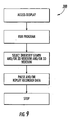
- FIGURE 9 a second program is required to play back previously recorded information as described above with respect to FIGURE 8 .
- the saved data from the sensors such as the photodiodes 40a-x can be displayed in a 900 x 900 intensity graph and/or as shown in FIGURE 7 to watch the spread of the simulated biological waste B as measured by changes in humidity, temperature or the photodiode intensity.
- the playback program according to FIGURE 9 can also include the intensity graph to show an X-Y streaming output that changes in amplitude and color intensity as the sensor voltage changes.
- the invention may be better understood with reference to an exemplary operation of the detection and analysis system 10 as described above.
- the mannequin 18 is connected to the controller 20 and to the computer 14 from within the light box 16.
- the mannequin 18 was left in a static position and signal levels of the photodiodes 40a-x were observed in two situations; i.e., with and without a product U donned.
- the signal level of the photodiodes 40a-x without the product U was approximately 1 V. With the product U donned, the signal levels were approximately an order of magnitude less. This was dependant on the location of the photodiode 40a-x with respect to the product U.
- the photodiodes 40a-x that are at the front waist region of the mannequin are severely attenuated due to the opaque nature of the PUB.material landing zone of the product U.
- the mannequin 18 was run through some simple non-repetitive dynamic motions to see the effects on the photodiodes 40a-x. Once the Dragon Skin ® was put in place on the mannequin 18, there was not immediate movement of the photodiodes 40a-x from the surface of the mannequin 18. Due to the rigidity of the heat shrink on the outside of the photodiode connection wires 45, it was suspected that the dynamics of the mannequin 18 may cause the photodiodes 40a-x and the wires 45 to come out of the surface of the mannequin 18. This may have been remedied due to two reasons.
- the wires 45 were probably molded in curved positions and this would prevent an angular placement of the wire 45 (with respects to the normal of the skin surface 22) to allow for it to be mobile within the mannequin 18.
- the clear skin 22 may act as a barrier that holds the photodiodes 40a-x in place. When placed on the mannequin 18, the skin 22 filled in around the photodiodes 40a-x and into the holes 22a-x of the mannequin 18. This may also help the stability of the photodiodes 40a-x in the mannequin 18.
- the photodiode mannequin 18 When donned with the product U and insulted with 60 mL of 10-3 simulant, the photodiode mannequin 18 clearly indicated the presence of a simulated bowel movement (BM) or simulant B when covered.
- BM simulated bowel movement
- simulant B simulant B
- the photodiodes 40a-x are also capable of assessing thickness of the simulant B covering one or more of the photodiodes 40a-x when the simulant B is thin enough and/or translucent to allow some light to pass.
- the edges of clear skin 22 were painted to the top 18A of the torso 18 and down to middle of the legs 18B,C.
- the clear skin 22 was placed into the hole surrounding the insult tube 26 and onto the tube.
- a sized o-ring was then slipped over the tube 26 to hold the skin 22 in place in case peeling occurred.
- the Dragon Skin ® works as a natural buffer for both the mannequin 18 and photodiodes 40a-x. If the skin 22 were to become stained with BM to a point where cleaning becomes problematic or begins to peel in the insult region, the skin can be easily stripped from the mannequin 18 and replaced.
- the original design of the light box 16 incorporated fluorescent lights due to their higher lumen output and temperature regulation. Despite spectral sensitivity data indicating otherwise, the photodiodes 40a-x did not provide an adequate output when exposed to fluorescent lighting. To correct this, the box 16 was retrofitted with incandescent bulbs 32a-x since the spectral sensitivity of the photodiodes 40a-x peaks in the high visible to near infrared region of the electromagnetic spectrum. This retrofit provided sufficient excitation for the photodiodes 40a-x.
- the temperature due to the incandescent bulbs 32a-x varied in the range of 83 to 84 degrees F after one hour of warm up and one hour of monitoring. Therefore, the temperature of the box 16 is acceptable and will create more real conditions (biological temperatures) for testing.
- the technician can rotate the individual photodiode intensity markers 52 about X-Y-Z axes on the display 28 of the computer 14 to present different aspects of the mannequin 18 in order to analyze the spread at particular points on the mannequin 18.
Landscapes
- Engineering & Computer Science (AREA)
- Health & Medical Sciences (AREA)
- Physics & Mathematics (AREA)
- General Physics & Mathematics (AREA)
- Life Sciences & Earth Sciences (AREA)
- Biomedical Technology (AREA)
- Chemical & Material Sciences (AREA)
- Business, Economics & Management (AREA)
- Medicinal Chemistry (AREA)
- General Health & Medical Sciences (AREA)
- Urology & Nephrology (AREA)
- Theoretical Computer Science (AREA)
- Educational Technology (AREA)
- Educational Administration (AREA)
- Computational Mathematics (AREA)
- Molecular Biology (AREA)
- Mathematical Physics (AREA)
- Mathematical Optimization (AREA)
- Mathematical Analysis (AREA)
- Algebra (AREA)
- Medical Informatics (AREA)
- Biophysics (AREA)
- Hematology (AREA)
- Pure & Applied Mathematics (AREA)
- Food Science & Technology (AREA)
- Analytical Chemistry (AREA)
- Biochemistry (AREA)
- Immunology (AREA)
- Pathology (AREA)
- Entrepreneurship & Innovation (AREA)
- Investigating Or Analysing Materials By Optical Means (AREA)
- Investigating Or Analysing Biological Materials (AREA)
Description
- Consumers desire an undergarment that reduces spread of biological waste in an undergarment, especially on a baby after the baby has had a bowel movement (BM) or has urinated. Accordingly, there have been efforts to develop dependable bench methods for performing real-time quantification of BM spread in an undergarment product during simulated mannequin use in order to improve an undergarment product.
- Some bench measurement methods have targeted BM spread in static mannequins. For example, the undergarment product is placed on a static mannequin and insulted with a BM simulant. Allowing for dwell time, the undergarment product is removed from the mannequin for inspection. The inspection is typically performed visually or by photographic records, which does not provide a real-time measure of BM spread. Moreover, analyses of visual and photographic data recorded in these measurements are often time intensive and tedious.
- To provide real-time measurements of BM spread within the undergarment product during simulated use, there have been only few practical options such as: video imaging within the undergarment; or sensing technology that utilizes a fundamental sensing parameter to provide a position of BM. However, these bench measurement methods suffer from a number of drawbacks.
- Video imaging within the undergarment is problematic for several reasons. First, the only practical method of mounting a camera to record the BM movement is within the mannequin. In order to mount within the mannequin, a clear mannequin material is required, but a clear mannequin material or skin is difficult to work with due to conformability and surface problems. Second, even if a camera is mounted within the clear skin, there are drawbacks associated with flat field imaging. Specifically, a mannequin body exhibits a curvature, which is imposed upon the donned undergarment. Therefore, a single camera cannot reliably image the BM spread without severe distortion to the resulting BM spread images. Moreover, if analysis of BM spread in a moving mannequin is desired, to produce the mannequin to test motion, a skeleton has to be employed to support the mannequin skin. Such a skeleton will interfere with imaging and limit space for camera placement.
- Identifying a sensing technology for real-time BM spread requires analysis of features of a system that can be sensed. A component lending itself to detection is the BM simulant. The BM simulant can be sensed by fluid conductivity or interruption of a sensed parameter. Both of these techniques are inherently discrete, which requires several sensors to simultaneously respond over a finite area to detect position of the BM simulant. For fluid conductivity sensing, the BM simulant would have to physically flow between two conducting materials. The conductive fluid would complete a circuit and single that the BM simulant is present in a particular position. Conductivity measurement, however, is problematic in a skin surface sensor array for a variety of reasons. First, there are no commercially available conductivity arrays in a film format with sufficient spatial resolution. The other method of conductivity measurement would be to use a simple conductivity probe constructed of two conductive materials acting as a single point sensor and building an array of probes to look at distribution of the BM simulant. Previous attempts to use this method for urine detection and distribution have been cumbersome and problematic due the size of the conductive surfaces and proximity of the conductive materials. Moreover, loss of spatial resolution and false signaling plagued setups of this type. Additionally, this sensing technique requires that the BM simulant be in contact with the conductivity probe. This may leave BM that spreads in an undergarment undetected if it were not to come in contact with the skin of the mannequin.
- A system is needed in the industry for real-time detection and spread analysis of biological waste in an undergarment.
-
US 2004/0118224 A1 discloses a prior art system and method for evaluating materials for use in absorbent articles. The method comprises placing the material proximate a simulated skin substrate, insulting the material with a fluid and, after a predetermined time, taking fluid loss measurements.US 2004/0118224 A1 discloses the features of the preambles of claims 1 and 13. -
EP 0 887 055 A1 - In general, the present invention provides a detection and analysis system using a mannequin motion system equipped with a sensor that senses a parameter. The parameter is interrupted by a biological waste spread to detect and analyzed the spread in real-time. The component parts of the detection and analysis system are simple and economical to manufacture, assemble and use. Other advantages of the invention will be apparent from the following description and the attached drawings, or can be learned through practice of the invention.
- As used herein, the term biological waste includes a simulated excrement, a simulated excretory product, a simulated exudate, a simulated bowel movement (BM), simulated feces, simulated urine, simulated menses, simulated blood and any other simulated human waste excretion.
- As used herein, the terms simulated and simulant are used to refer to any manufactured materials, objects and fluids and can mean virtual, artificial, synthetic and the like.
- As used herein, the term undergarment means any diaper, childcare, feminine care, adult care, healthcare or other undergarment.
- According to one aspect of the invention, a system for analyzing biological waste in an undergarment is provided, as set forth in claim 1.
- In one embodiment, the mannequin simulates human motion in order to better simulate biological waste spread such as when a toddler walks around a room. The evacuation port of the mannequin can simulate a human anus with the excretory product being a feces simulant for elimination through the simulated anus. Also in this aspect, an insult port can be provided for insulting simulated human urine from the mannequin into the undergarment is provided.
- At least one of the sensors in this aspect of the invention is a photodiode disposed in the skin surface of the mannequin. A light source can be located about the mannequin to produce the light emission to activate the photodiode. The photodiode senses a light emission external to the skin surface and signals the computer when the excretory product is affecting the light emission. More particularly, the photodiode can be substantially flush with the skin surface, and is disposed under a transparent polymer coating, which itself is coated on the skin surface. The excretory product can be opaque in appearance to block the light emission, but it can also be translucent to alter the light emission. Likewise, the simulated human urine can include a darkening agent to affect sensing by the sensors.
- At least one of the sensors in this aspect of the invention can be a heat sensor disposed in the mannequin at least partially exposed to an ambient environment. The heat sensor senses a presence of the excretory product when a temperature of the excretory product is greater than an ambient temperature in the ambient environment.
- At least one of the sensors can also be a humidity sensor disposed in the mannequin. The humidity sensor senses a humidity of the excretory product.
- The computer records the dispersion pattern being produced by the excretory product being sensed by the sensors. The computer includes means for replaying the recorded dispersion pattern for a user to analyze the dispersion pattern being formed in real-time. Additionally, the system can include means for programming the computer to convert the excretory product into the dispersion pattern. The means for programming can be a software program configured to record the dispersion pattern in real-time and replay the dispersion pattern for analysis.
- According to another aspect of the invention, a method is provided, as set forth in claim 13.
- The method can also include the step of injecting a darkening agent in the excretory product such that the excretory product exhibits an opaque appearance to block the emission.
- The method can also accommodate the step of placing the mannequin in motion while the excretory product is being eliminated from the evacuation port into the undergarment.
- Other aspects and advantages of the invention will be apparent from the following description and the attached drawings, or can be learned through practice of the invention.
- A full and enabling disclosure of the present invention, including the best mode thereof to one of ordinary skill in the art, is set forth more particularly in the remainder of the specification, including reference to the accompanying figures in which:
-
FIGURE 1 is a perspective view of a detection and analysis system according to one embodiment of the invention; -
FIGURE 2 is a schematic view of a portion of the detection and analysis system as inFIGURE 1 ; -
FIGURE 3A is a top perspective view of a mannequin as used in the detection and analysis system ofFIGURE 2 ; -
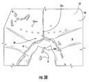
FIGURE 3B is a bottom perspective view of the mannequin as inFIGURE 3A ; -
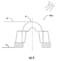
FIGURE 4 is an elevational view of a photodiode as used in one embodiment of the invention; -
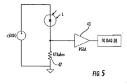
FIGURE 5 is a schematic diagram showing operation of the photodiode as inFIGURE 4 ; -
FIGURE 6 is a schematic diagram showing placement points in the mannequin for the photodiodes ofFIGURE 4 ; -
FIGURE 7 is an elevational view of a display showing an intensity graph relative to the schematic diagram ofFIGURE 6 ; -
FIGURE 8 is a flow chart of a computer program for recording real-time biological waste spread in accordance with an aspect of the invention; and -
FIGURE 9 is a flow chart of a computer program for playing back a recorded biological waste spread as inFIGURE 8 . - Detailed reference will now be made to the drawings in which examples embodying the present invention are shown. Repeat use of reference characters in the drawings and detailed description is intended to represent like or analogous features or elements of the present invention.
- The drawings and detailed description provide a full and detailed written description of the invention and the manner and process of making and using it, so as to enable one skilled in the pertinent art to make and use it. The drawings and detailed description also provide the best mode of carrying out the invention. However, the examples set forth herein are provided by way of explanation of the invention and are not meant as limitations of the invention. The present invention thus includes modifications and variations of the following examples as come within the scope of the appended claims and their equivalents.
- As broadly embodied in the figures, a detection and analysis system is provided with sensors that sense a parameter, which can be interrupted by a simulated biological waste in an undergarment for detection and analysis of a spread of the simulated biological waste. The detection and analysis system broadly includes a mannequin motion system with a movable mannequin connected to a movement controller within a light box. The mannequin is in electronic communication with a computer for relaying collected data relative to the mannequin. The skilled artisan will instantly recognize that the components of the detection and analysis system, described in detail below and their materials and dimensions are modifiable to accommodate various manufacturing and testing requirements and are limited to only those examples shown in the figures.
- A first embodiment of a detection and analysis system, designated in general by the
element number 10, is shown inFIGS. 1-5 . The detection andanalysis system 10 broadly includes amannequin motion system 12, acomputer 14, alight box 16, amannequin 18 and acontroller 20. By way of brief introduction, themannequin 18 is electrically connected to thecomputer 14 and thecontroller 20 within thelight box 16. An undergarment U (shown in phantom for clarity) is attached to themannequin 18 in a known manner and a simulated biological waste product B is insulted through themannequin 18 into the undergarment U. As will be described in greater detail below, a number of sensors such asphotodiodes 40 are embedded in or located near a surface orsimulated skin 22 of themannequin 18. As the biological waste B passes over thephotodiodes 40, thephotodiodes 40 register the presence of the biological waste B due to an attenuation of incoming light that is normally received by thephotodiodes 40. Further details of the photodiodes and alternative sensors as well as other components of the detection andanalysis system 10, its material makeup, arrangement and examples of its operation are provided in greater detail below. - With particular reference to
FIGURES 1 and2 , the detection andanalysis system 10 utilizes thelight box 16 with a plurality of sensors such asphotodiodes 40a-x (where x represents a theoretically limitless number of photodiodes), which are situated in themannequin 18. As discussed in greater detail below, in addition to thephotodiodes 40a-x, or alternatively, a plurality of heat sensors 56a-x and humidity sensors 60a-x can be used by the detection andanalysis system 10. - As shown most clearly in
FIGURE 1 , themannequin 18 is positioned within thelight box 16, which includes three walls 16A-C, a ceiling 16D, a floor 16E and a door 16F. As shown, themannequin 18 includes asimulated skin 22 and forms a torso 18A and left and right legs 18B,C. Themannequin 18 also includes an evacuation port 26 (alternatively, insult port or aperture) defined through thesimulated skin 22. The legs 18A,B are connected to thecontroller 20 to control movement of themannequin 18 as will be described below. As further shown, a biologicalwaste simulant container 36 is connected to themannequin 18 via atube 24 that extends to theevacuation port 26. Themannequin 18 is also connected to thecomputer 14 and a data acquisition card (DAQ) 30. TheDAQ 30 collects data on the simulated biological waste B spread in the undergarment U and displays that data on adisplay 28 as will be described below. -
FIGURE 1 further shows a plurality of mounted light fixtures 32a-x (where x represents a theoretically unlimited number of fixtures). Also shown, at least twomobile fixtures 34a,b known as "trouble lights" can be positioned as desired to change an emission of light rays L or intensity relative to certain aspects of themannequin 18.FIGURE 1 also illustrates potential directions of motion by the legs 18A,B via thecontroller 20 as indicated by the bold arrows labeled M. - Turning now to
FIGURE 2 , a portion of the detection andanalysis system 10 is shown schematically. As shown, thecomputer 14 is interfaced to amultiplexer 42 such as a four slot SCXI series chassis available from National Instruments Corporation, Austin, Texas. As shown, four (4)photodiode arrays 38a-d, each having thirty-twophotodiodes 40a-x, are interfaced torespective modules 44a-d, which are connected to themultiplexer 42. In this aspect of the invention, theDAQ 30 is an NI PCI-6036e card also available from National Instruments Corporation. The National Instruments DAQ and related system is suitable due to flexibility, expandability, accuracy and programming ease. For instance, the NI PCI-6036e card provides sixteen-bit accuracy (greater than 65,000 levels) on analog inputs at 200-kilo samples/second. However, since the NI PCI-6036e card allows only sixteen single-ended or eight differential inputs, a signal conditioning/multiplexing chassis, themultiplexer 42, is used to expand the range of theDAQ 30 in this exemplary set up. The skilled artisan will instantly recognize that other data acquisition systems and cards can be used; therefore, theDAQ 30 of the detection andanalysis system 10 is not limited to the NI PCI-6036e card, which is an example only. Moreover, use of a greater capacity acquisition card that allows more than sixteen single-ended or eight differential inputs can eliminate the need for themultiplexer 42 as used in this example. - With continued reference to
FIGURE 2 , themultiplexer 42 is shown loaded with the four modules 44A-D. The modules 44A-D are each SCXI-1032 channel analog input modules that provide a total of 128 analog input channels. The 128 channels are multiplexed by themultiplexer 42 to theDAQ card 30 channels through themultiplexer 42. The modules 44A-D are connectible to the photodiode arrays 38A-D through removable shielded terminal blocks (not shown). -
FIGURE 2 further shows the plurality of heat sensors 56a-x and humidity sensors 60a-x briefly introduced above. As shown, aheat sensor array 54 includes the plurality of heat sensors 56a-x. The heat sensors 56a-x are interfaced to one of themodules 44a-d, which are connected to themultiplexer 42 as described above. Likewise, ahumidity sensor array 58 includes the plurality of humidity sensors 60a-x, which is also connected to themultiplexer 42. For clarity, only oneheat sensor array 54 and only onehumidity sensor array 58 are shown inFIGURE 2 , but those skilled in the art will recognize that multiple arrays, each containing multiple sensors, can be employed in the detection andanalysis system 10. The heat sensors 56a-x and the humidity sensors 60a-x can be physically arranged on, in or about themannequin 18 for sensing heat and humidity, respectively, in real time in a manner similar to thephotodiodes 40a-x as discussed below. - Turning now to
FIGURE 3A , themannequin 18 is more particularly shown connected to thecontroller 20 and themultiplexer 42, which are powered by apower supply 46. As shown, a plurality ofrecesses 22a-x are defined in thesimulated skin 22 of themannequin 18. In this example, thesimulated skin 22 is a polymer although various elastomeric materials can be used, which have sufficient extensibility and elastic recovery properties. A plurality of electrical connectingwires 45 is used to connect the sensors such as thephotodiodes 40a-x to themodules 44a-x, which are connected to themultiplexer 42. Thewires 45 can be two-conductor, sealed wire obtained from manufacturers such as Bay Associates of Menlo Park, California, which can custom create thewires 45 to be small, flexible 36 AWG gauge wire. As further shown, the legs 18B,C are connected by cables/serial ports 47 to thecomputer 14 as known to the skilled artisan, and the electrical connectingwires 45 connect thecontroller 20 to thepower supply 46 to control movement of themannequin 18. - With reference to both
FIGURES 3A and3B , therecesses 22a-x are used to position thephotodiodes 40a-x, the heat sensors 56a-x, and the humidity sensors 60a-x, as well as other sensors and combinations of these sensors, in or on themannequin 18. AsFIGURE 3B particularly shows, theevacuation port 26 can be a simulated anus 26A or a simulated urethra 26B. To prevent the simulated biological waste B from flowing into therecesses 22a-x from theevacuation port 26 and contacting the sensors or the electrical connectingwires 45, a protective compound or covering 48 is used to coat themannequin 18. The covering 48 can be a silicone rubber compound such as Dragon Skin™ brand available from Smooth On, Inc. Such a silicone rubber compound is also durable and flexible, which is useful for repetitive motions when themannequin 18 is put into motion by thecontroller 20. - Turning now to
FIGURE 4 , one sensor according to an aspect of the invention is thephotodiode 40a-x as briefly introduced above. Thephotodiode 40a-x includes an N and P type silicone sandwiched together for exposure to ambient lighting such as the mounted fixtures 32a-x and mobile fixtures 34A,B as described above. Thephotodiodes 40 each have alens 41 for passage of the light rays L. In this example, thelens 41 is located near theskin surface 22 as described above. In use, when a reverse bias voltage is applied to thephotodiode 40, a "depletion region" (lack of electrical charge) is created in the PN junction. As photons of certain wavelengths from the light rays L fall on the depletion region, an electron hole pair is created. The electron hole pair separate with an electron entering the N-type silicone and the hole entering the P-type, which results in a current generated by the light rays incident upon thephotodiode 40. Migration of holes and electrons to their respective regions is known as the photovoltaic effect. - With reference to
FIGURES 4 and5 , a basic circuit to read a current from thephotodiode 40a-x is shown. As introduced above, the light rays L reach thelens 41 of thephotodiode 40a-x to allow current to flow that is proportional to intensity and wavelength of the light rays L. In this aspect of the invention, the input to a programmable gain instrumentation amp (PGIA) 43 located on the analog input module has relatively high impedance; thus, most of the current flows through a Kilo-ohm resistor 47 as shown, which creates a voltage drop. This voltage is amplified and multiplexed back to theDAQ card 30 where the voltage drop is then reported to software loaded in thecomputer 14, which will be described below. -
FIGURE 6 most clearly shows the plurality ofphotodiode recesses 22a-x in theskin 22 of themannequin 18 arranged for detecting and monitoring the simulated biological waste B spread when the undergarment U is placed around themannequin 18 in a typical fashion. As noted above, thelens 41 of eachphotodiode 40a-x rests in, or possibly slightly protrudes from, the photodiode recesses 22a-x. More particularly, eachlens 41 is substantially flush with theskin 22 as will be described example operation below. -
FIGURE 7 most clearly shows thedisplay 28 of thecomputer 14 as briefly introduced above. As shown, a two-dimensional intensity graph 50 related to a sensed output of thephotodiodes 40a-x (seeFIGURE 4 ) is shown. Individualphotodiode intensity markers 52 are on the order of a picture element (pixel). -
FIGURE 8 shows creation of a data-recording program for use with the detection andanalysis system 10. In this aspect of the invention, LabView® programming language, available from National Instruments Corporation, is used to create the recording program. The recording program is used to record incoming data from sensors such as thephotodiodes 40a-x as described above with respect toFIGURES 1-7 . An output of themultiplexer 42 is recorded using, by example, a LabView® data acquisition subroutine. The subroutine allows for the analog-to-digital conversion-of the sensor input so that the output can be recorded and displayed within the LabView® program (seeFIGURE 7 ). - Turning now to
FIGURE 9 , a second program is required to play back previously recorded information as described above with respect toFIGURE 8 . The saved data from the sensors such as thephotodiodes 40a-x can be displayed in a 900 x 900 intensity graph and/or as shown inFIGURE 7 to watch the spread of the simulated biological waste B as measured by changes in humidity, temperature or the photodiode intensity. The playback program according toFIGURE 9 can also include the intensity graph to show an X-Y streaming output that changes in amplitude and color intensity as the sensor voltage changes. - The invention may be better understood with reference to an exemplary operation of the detection and
analysis system 10 as described above. - With particular reference to
FIGURES 1-5 , themannequin 18 is connected to thecontroller 20 and to thecomputer 14 from within thelight box 16. - For first-use evaluation, the
mannequin 18 was left in a static position and signal levels of thephotodiodes 40a-x were observed in two situations; i.e., with and without a product U donned. The signal level of thephotodiodes 40a-x without the product U was approximately 1 V. With the product U donned, the signal levels were approximately an order of magnitude less. This was dependant on the location of thephotodiode 40a-x with respect to the product U. Thephotodiodes 40a-x that are at the front waist region of the mannequin are severely attenuated due to the opaque nature of the PUB.material landing zone of the product U. Also in the crotch region of the product U, there is extensive bunching and overlapping of cover/core materials, which attenuates the light entering. Higher wattage light sources 32a-x can be used to increase the depth of penetration of light into the product U. The caveat to the higher wattage sources 32a-x is the higher heat conditions inside of thebox 16. The distance of the sources 32a-x from thephotodiodes 40a-x will also play a part in the flux of light though the product U. The inverse square law for radiant sources must be considered for this setup. The law states that the intensity from the radiant source will diminish with relation to the inverse square of the distance. Therefore, the farther removed the lighting 32a-x, the larger the attenuation of intensity. Customized lighting, such astrouble lights 34a,b is flexible and invasive enough to eliminate this attenuation problem. - The
mannequin 18 was run through some simple non-repetitive dynamic motions to see the effects on thephotodiodes 40a-x. Once the Dragon Skin® was put in place on themannequin 18, there was not immediate movement of thephotodiodes 40a-x from the surface of themannequin 18. Due to the rigidity of the heat shrink on the outside of thephotodiode connection wires 45, it was suspected that the dynamics of themannequin 18 may cause thephotodiodes 40a-x and thewires 45 to come out of the surface of themannequin 18. This may have been remedied due to two reasons. First, despite the mold release that was placed on the heat shrink of thewires 45, thewires 45 were probably molded in curved positions and this would prevent an angular placement of the wire 45 (with respects to the normal of the skin surface 22) to allow for it to be mobile within themannequin 18. Second, theclear skin 22 may act as a barrier that holds thephotodiodes 40a-x in place. When placed on themannequin 18, theskin 22 filled in around thephotodiodes 40a-x and into theholes 22a-x of themannequin 18. This may also help the stability of thephotodiodes 40a-x in themannequin 18. - When donned with the product U and insulted with 60 mL of 10-3 simulant, the
photodiode mannequin 18 clearly indicated the presence of a simulated bowel movement (BM) or simulant B when covered. An additional observation that was made during the testing was that at the edge of the insult spread region, the output signal of thephotodiode 40a-x did not drop suddenly.Photodiodes 40a-x at the edge of the BM slowly decreased in output until covered by enough simulant B to block all extent light. This indicates thephotodiodes 40a-x are sensitive to thickness changes in the BM to a point. Alternatively stated, in addition to thephotodiodes 40a-x being able to detect varying light intensities, thephotodiodes 40a-x are also capable of assessing thickness of the simulant B covering one or more of thephotodiodes 40a-x when the simulant B is thin enough and/or translucent to allow some light to pass. - To prevent moisture from contacting the edges of the
clear skin 22 at the point of interface with themannequin surface 18, the edges ofclear skin 22 were painted to the top 18A of thetorso 18 and down to middle of the legs 18B,C. Around theBM insult point 26, theclear skin 22 was placed into the hole surrounding theinsult tube 26 and onto the tube. A sized o-ring was then slipped over thetube 26 to hold theskin 22 in place in case peeling occurred. The Dragon Skin® works as a natural buffer for both themannequin 18 andphotodiodes 40a-x. If theskin 22 were to become stained with BM to a point where cleaning becomes problematic or begins to peel in the insult region, the skin can be easily stripped from themannequin 18 and replaced. - The original design of the
light box 16 incorporated fluorescent lights due to their higher lumen output and temperature regulation. Despite spectral sensitivity data indicating otherwise, thephotodiodes 40a-x did not provide an adequate output when exposed to fluorescent lighting. To correct this, thebox 16 was retrofitted with incandescent bulbs 32a-x since the spectral sensitivity of thephotodiodes 40a-x peaks in the high visible to near infrared region of the electromagnetic spectrum. This retrofit provided sufficient excitation for thephotodiodes 40a-x. The temperature due to the incandescent bulbs 32a-x varied in the range of 83 to 84 degrees F after one hour of warm up and one hour of monitoring. Therefore, the temperature of thebox 16 is acceptable and will create more real conditions (biological temperatures) for testing. - While the exemplary software used in the foregoing testing was capable of recording and subsequently playing back the recorded data, real-time playback speed can be increased in order for a user to more quickly observe the data as it is being collected. Therefore, other software can be substituted to permit even more rapid displays of large intensity graphs in order to improve the real-time display ability of the
system 10. Additionally, alternative software can be loaded in thecomputer 14 to provide three-dimensional analyses of biological waste spread. Such "3D" software is available, for instance, from National Instruments Corporation to enable a technician to operate thecomputer 14 in a manner similar to that described above with respect toFIGS. 7-9 . Specifically, by selecting the 3D window inFIG. 9 , the technician can rotate the individualphotodiode intensity markers 52 about X-Y-Z axes on thedisplay 28 of thecomputer 14 to present different aspects of themannequin 18 in order to analyze the spread at particular points on themannequin 18.
Claims (17)
- A system (10) for analyzing biological waste in an undergarment, the system (10) comprising:a mannequin (18) having a simulated skin surface (22) and defining an evacuation port (26) therethrough, the evacuation port (26) being configured to eliminate a simulated human excretory product from the mannequin (18); characterised bya plurality of sensors disposed about the evacuation port (26), each sensor being configured for sensing the excretory product as the excretory product is eliminated through the evacuation port (26) into an undergarment disposed about the mannequin (18); anda computer (14) in communication with the sensors, the computer (14) being configured for converting the sensed excretory product into a dispersion pattern defined in the undergarment;wherein at least one of the sensors is a photodiode (40a-x) disposed in the skin surface (22) of the mannequin (18), the photodiode (40a-x) being configured to sense a light emission external to the skin surface (22), the photodiode (40a-x) being further configured to signal the computer (14) when the excretory product is affecting the light emission, and wherein the photodiode (40a-x) is disposed under a transparent polymer coating, the transparent polymer coating disposed on the skin surface (22).
- The system (10) as defined in Claim 1, wherein the mannequin (18) is configured to simulate human motion.
- The system (10) as defined in Claim 1 or 2, wherein the photodiode (40a-x) is substantially flush with the skin surface (22).
- The system (10) as defined in any one of the preceding claims, wherein the evacuation port (26) is selected from the group consisting of a simulated anus, a simulated urethra, and combinations thereof.
- The system (10) as defined in Claims 3 or 4, wherein the excretory product is opaque in appearance to block the light emission, or translucent in appearance to alter the light emission.
- The system (10) as defined in any one of the preceding claims, wherein the excretory product is one of a feces simulant or a menses simulant
- The system (10) as defined in any one of the Claims 3-6, further comprising a light source disposed about the mannequin (18), the light source being configured to produce the light emission to activate the photodiode (40a-x).
- The system (10) as defined in any one of the preceding claims, wherein at least one of the sensors is a heat sensor (56a-x) disposed in the mannequin (18) at least partially exposed to an ambient environment, the heat sensor (56a-x) being configured to sense a presence of the excretory product when a temperature of the excretory product is greater than an ambient temperature in the ambient environment, or at least one of the sensors is a humidity sensor (60a-x) disposed in the mannequin (18), the humidity sensor (60a-x) being configured to sense a humidity of the excretory product.
- The system (10) as defined in any one of the preceding claims, wherein the computer (14) is configured to record the dispersion pattern being produced by the excretory product being sensed by the sensors.
- The system (10) as defined in Claim 9, wherein the computer (14) includes means for replaying the recorded dispersion pattern for a user to analyze the dispersion pattern being formed in real-time.
- The system (10) as defined in Claims 1, 9 or 10, further comprising means for programming the computer (14) to convert the excretory product into the dispersion pattern, preferably the means for programming includes a software program being configured to record the dispersion pattern in real-time and replay the dispersion pattern for analysis.
- The system (10) as defined in any one of the preceding claims, further comprising an insult port being configured to insult simulated human urine from the mannequin (18) into the undergarment, preferably the simulated human urine includes a darkening agent to affect sensing by the sensors.
- A method of determining biological waste dispersion in an undergarment, the method comprising the steps of:providing a mannequin (18) defining an evacuation port (26) therethrough, the evacuation port (26) being configured to eliminate a simulated human excretory product from the mannequin (18);characterised by the steps of:disposing a plurality of sensors about the evacuation port (26), each sensor being configured for sensing the excretory product as the excretory product is eliminated from the evacuation port (26) into an undergarment disposed about the mannequin (18), wherein at least one of the sensors is a photodiode (40a-x) substantially flush with a simulated skin surface (22) of the mannequin (18) such that an emission from a light source is affected by the excretory product as the excretory product moves between the photodiode (40a-x) and the light source, and wherein the photodiode (40a-x) is disposed under a transparent coating, the transparent coating disposed about the simulated skin surface (22); andproviding a computer (14) in communication with the sensors, the computer (14) being configured for converting the sensed excretory product into a dispersion pattern defined in the undergarment.
- The method as defined in Claim 13, wherein the sensors are a plurality of photodiodes (40a-x), a plurality of heat sensors (56a-x), a plurality of humidity sensors (60a-x) or a combination thereof.
- The method as defined in Claims 13 or 14, further comprising the step of injecting a darkening agent in the excretory product such that the excretory product exhibits an opaque appearance to block the emission.
- The method as defined in any one of the Claims 13-15, further comprising the steps of recording a dispersion pattern of the excretory product being sensed by the sensors and replaying the dispersion pattern of the excretory product for a user to analyze the dispersion pattern.
- The method as defined in any one of the Claims 13-16, further comprising the step of placing the mannequin (18) in motion while the excretory product is being eliminated from the evacuation port (26) into the undergarment.
Applications Claiming Priority (2)
| Application Number | Priority Date | Filing Date | Title |
|---|---|---|---|
| US11/216,859 US20070048709A1 (en) | 2005-08-31 | 2005-08-31 | System for detection and analysis of biological waste spread in an undergarment |
| PCT/US2006/015289 WO2007027219A1 (en) | 2005-08-31 | 2006-04-24 | System for detection and analysis of biological waste spread in an undergarment |
Publications (2)
| Publication Number | Publication Date |
|---|---|
| EP1920232A1 EP1920232A1 (en) | 2008-05-14 |
| EP1920232B1 true EP1920232B1 (en) | 2010-04-14 |
Family
ID=36869900
Family Applications (1)
| Application Number | Title | Priority Date | Filing Date |
|---|---|---|---|
| EP06758508A Expired - Lifetime EP1920232B1 (en) | 2005-08-31 | 2006-04-24 | System for detection and analysis of biological waste spread in an undergarment |
Country Status (4)
| Country | Link |
|---|---|
| US (1) | US20070048709A1 (en) |
| EP (1) | EP1920232B1 (en) |
| DE (1) | DE602006013653D1 (en) |
| WO (1) | WO2007027219A1 (en) |
Cited By (4)
| Publication number | Priority date | Publication date | Assignee | Title |
|---|---|---|---|---|
| US10064767B2 (en) | 2012-08-01 | 2018-09-04 | The Procter & Gamble Company | Diaper structure with enhanced tactile softness attributes and providing relatively low humidity |
| US10195092B2 (en) | 2014-03-06 | 2019-02-05 | The Procter & Gamble Company | Multi-component topsheets |
| US10206826B2 (en) | 2014-03-06 | 2019-02-19 | The Procter & Gamble Company | Three-dimensional substrates |
| US10285874B2 (en) | 2014-03-06 | 2019-05-14 | The Procter & Gamble Company | Multi-component topsheets |
Families Citing this family (24)
| Publication number | Priority date | Publication date | Assignee | Title |
|---|---|---|---|---|
| US7566222B2 (en) * | 2004-11-12 | 2009-07-28 | First Quality Retail Services, Llc | Method, apparatus and kit for demonstrating the use of absorbent products |
| US8737704B2 (en) | 2006-08-08 | 2014-05-27 | The Procter And Gamble Company | Methods for analyzing absorbent articles |
| US20090043272A1 (en) * | 2007-08-08 | 2009-02-12 | Tyco Healthcare Retail Services Ag | Training pant article and method for manufacturing |
| US8274393B2 (en) | 2008-12-31 | 2012-09-25 | Kimberly-Clark Worldwide, Inc. | Remote detection systems for absorbent articles |
| US8866624B2 (en) * | 2008-12-31 | 2014-10-21 | Kimberly-Clark Worldwide, Inc. | Conductor-less detection system for an absorbent article |
| US8266956B2 (en) * | 2009-06-10 | 2012-09-18 | The Procter & Gamble Company | Process for demonstrating tissue product break-through |
| US8156821B2 (en) * | 2009-06-10 | 2012-04-17 | The Procter & Gamble Company | Apparatus for determining tissue product break-through |
| US8127601B2 (en) * | 2009-06-10 | 2012-03-06 | The Procter & Gamble Company | Process for determining tissue product break-through |
| DE102009054097A1 (en) * | 2009-11-12 | 2011-05-19 | Paul Hartmann Aktiengesellschaft | A method of determining moisture in an absorbent sanitary article and apparatus for carrying out the method |
| US8698641B2 (en) | 2010-11-02 | 2014-04-15 | Kimberly-Clark Worldwide, Inc. | Body fluid discriminating sensor |
| CN102800230A (en) * | 2011-05-24 | 2012-11-28 | 天津市天堰医教科技开发有限公司 | Method for detecting disinfection positions of female urethra |
| US9244022B2 (en) | 2011-06-16 | 2016-01-26 | The Procter & Gamble Company | Mannequins for use in imaging and systems including the same |
| US20130052624A1 (en) * | 2011-08-25 | 2013-02-28 | Miguel Saps | Tridimensional stool assessment instrument, methods, and uses thereof |
| US8933292B2 (en) | 2011-10-28 | 2015-01-13 | Kimberly-Clark Worldwide, Inc. | Absorbent article with sensor array for body exudate detection |
| US9119748B2 (en) | 2011-10-28 | 2015-09-01 | Kimberly-Clark Worldwide, Inc. | Electronic discriminating device for body exudate detection |
| US8816149B2 (en) | 2011-10-28 | 2014-08-26 | Kimberly-Clark Worldwide, Inc. | System for detection and monitoring of body exudates using a gas emitting substance for use in interactive toilet training |
| JP2013164277A (en) * | 2012-02-09 | 2013-08-22 | Gunze Ltd | Torso and evaluation method using torso |
| MX2015001212A (en) | 2012-08-01 | 2015-04-10 | Procter & Gamble | Diaper structure with enhanced tactile softness attributes. |
| CA2976512A1 (en) | 2015-02-27 | 2016-09-01 | Kimberly-Clark Worldwide, Inc. | Absorbent article leakage assessment system |
| WO2017034796A1 (en) | 2015-08-26 | 2017-03-02 | The Procter & Gamble Company | Absorbent articles having three-dimensional substrates and indicia |
| JP6759369B2 (en) | 2016-07-01 | 2020-09-23 | ザ プロクター アンド ギャンブル カンパニーThe Procter & Gamble Company | Absorbent article with improved topsheet dryness |
| WO2018186842A1 (en) | 2017-04-05 | 2018-10-11 | Kimberly-Clark Worldwide, Inc. | Garment for detecting absorbent article leakage and methods of detecting absorbent article leakage utilizing the same |
| GB2591114B (en) * | 2020-01-16 | 2023-10-25 | Limbs & Things Ltd | Fluid simulation apparatus |
| CN111579562A (en) * | 2020-05-16 | 2020-08-25 | 台州市椒江芝雅服饰有限公司 | Socks detection utensil with interior illumination lamp body |
Family Cites Families (37)
| Publication number | Priority date | Publication date | Assignee | Title |
|---|---|---|---|---|
| US1561285A (en) * | 1920-01-20 | 1925-11-10 | Westinghouse Electric & Mfg Co | Apparatus for testing the rate of liquid absorption by fabrics or the like |
| US2545281A (en) * | 1948-10-19 | 1951-03-13 | Inst Textile Tech | Fabric moisture absorbency tester |
| US3502763A (en) * | 1962-02-03 | 1970-03-24 | Freudenberg Carl Kg | Process of producing non-woven fabric fleece |
| US3502538A (en) * | 1964-08-17 | 1970-03-24 | Du Pont | Bonded nonwoven sheets with a defined distribution of bond strengths |
| US3341394A (en) * | 1966-12-21 | 1967-09-12 | Du Pont | Sheets of randomly distributed continuous filaments |
| US3542615A (en) * | 1967-06-16 | 1970-11-24 | Monsanto Co | Process for producing a nylon non-woven fabric |
| NL6713062A (en) * | 1967-09-25 | 1969-03-27 | ||
| GB1453447A (en) * | 1972-09-06 | 1976-10-20 | Kimberly Clark Co | Nonwoven thermoplastic fabric |
| US3952584A (en) * | 1975-03-04 | 1976-04-27 | Lichstein Bernard M | Measurement of absorbency characteristics of absorbent structures |
| DE2900690A1 (en) * | 1979-01-10 | 1980-07-24 | Bosch Gmbh Robert | DEVICE FOR TEMPERATURE CONTROL OF A MEASURING PURPOSE OF RESISTANCE, ESPECIALLY IN COMBUSTION ENGINES |
| US4257188A (en) * | 1979-01-30 | 1981-03-24 | Cpg Products Corp. | Toy dolls and figurines having surface portions of reversibly changeable color |
| US4340563A (en) * | 1980-05-05 | 1982-07-20 | Kimberly-Clark Corporation | Method for forming nonwoven webs |
| US4423471A (en) * | 1982-09-15 | 1983-12-27 | Mycro-Group Company | Mobile lighting fixture, method and boom |
| US4720415A (en) * | 1985-07-30 | 1988-01-19 | Kimberly-Clark Corporation | Composite elastomeric material and process for making the same |
| US4932919A (en) * | 1989-03-13 | 1990-06-12 | Mattel, Inc. | Posable figure with continuous skin |
| US5066259A (en) * | 1990-05-17 | 1991-11-19 | Acker Judith S | Doll structure incorporating material simulating natural body weight and feel |
| US5067924A (en) * | 1990-10-10 | 1991-11-26 | Munter Beverly L | Doll for simulating weight loss/gain |
| US5419729A (en) * | 1992-02-07 | 1995-05-30 | Gross; Flora G. | Toy, doll or mannequin with dimensionally varible exterior surface |
| US5361627A (en) * | 1992-12-31 | 1994-11-08 | Johnson & Johnson Inc. | Method and apparatus for the measuring the capillary attraction developed at a surface of an absorbent body |
| US5425265A (en) * | 1993-12-20 | 1995-06-20 | Jaisinghani; Rajan A. | Apparatus and method for measuring the capillary pressure distribution of porous materials |
| US5518436A (en) * | 1994-07-11 | 1996-05-21 | Cap Toys Inc. | Toy figure and manifold assembly therefor |
| US5913708A (en) * | 1995-05-26 | 1999-06-22 | Gross; Flora Geane | Toy, doll or mannequin with dimensionally variable exterior surface |
| US6015935A (en) * | 1997-03-27 | 2000-01-18 | The Procter & Gamble Company | Absorbent articles comprising a material having a high vertical wicking capacity |
| DE69730123T2 (en) * | 1997-06-25 | 2005-08-18 | The Procter & Gamble Company, Cincinnati | Evaluation method for disposable absorbent articles |
| US6107537A (en) * | 1997-09-10 | 2000-08-22 | The Procter & Gamble Company | Disposable absorbent articles providing a skin condition benefit |
| US6152906A (en) * | 1998-08-25 | 2000-11-28 | Kimberly-Clark Worldwide, Inc. | Absorbent article having improved breathability |
| FR2787572B1 (en) * | 1998-12-17 | 2001-02-02 | Franck Courtray | DEVICE FOR PERFORMING TESTS ON ABSORBENT SUBSTRATES |
| AR027842A1 (en) * | 1999-08-23 | 2003-04-16 | Kimberly Clark Co | AN ABSORBENT ARTICLE WHICH MAINTAINS OR IMPROVES SKIN HEALTH |
| US6534074B2 (en) * | 1999-08-24 | 2003-03-18 | Kimberly-Clark Worldwide, Inc. | Absorbent articles providing skin health benefits |
| US6464537B1 (en) * | 1999-12-29 | 2002-10-15 | Berg Technology, Inc. | High speed card edge connectors |
| US6413142B1 (en) * | 2000-09-02 | 2002-07-02 | Virginia Weastler | Expandable doll or the like |
| US6639665B2 (en) * | 2001-02-09 | 2003-10-28 | Institute For Technology Development | Multispectral imaging system for contaminant detection |
| US6543657B2 (en) * | 2001-03-20 | 2003-04-08 | Hong Kong Polytechnic University | Thermal manikin |
| US6557398B2 (en) * | 2001-03-28 | 2003-05-06 | Sca Hygiene Products Ab | Method and a device for determining the liquid retention of absorbent articles |
| US7174774B2 (en) * | 2002-08-30 | 2007-02-13 | Kimberly-Clark Worldwide, Inc. | Method and apparatus of detecting pooling of fluid in disposable or non-disposable absorbent articles |
| US6904820B2 (en) * | 2002-12-20 | 2005-06-14 | Kimberly-Clark Worldwide, Inc. | Method of using a simulated skin substrate and method for determining material dryness performance |
| US6931951B2 (en) * | 2002-12-20 | 2005-08-23 | Kimberly-Clark Worldwide, Inc. | Mechanical device with simulated skin substrate |
-
2005
- 2005-08-31 US US11/216,859 patent/US20070048709A1/en not_active Abandoned
-
2006
- 2006-04-24 WO PCT/US2006/015289 patent/WO2007027219A1/en not_active Ceased
- 2006-04-24 DE DE602006013653T patent/DE602006013653D1/en not_active Expired - Lifetime
- 2006-04-24 EP EP06758508A patent/EP1920232B1/en not_active Expired - Lifetime
Cited By (4)
| Publication number | Priority date | Publication date | Assignee | Title |
|---|---|---|---|---|
| US10064767B2 (en) | 2012-08-01 | 2018-09-04 | The Procter & Gamble Company | Diaper structure with enhanced tactile softness attributes and providing relatively low humidity |
| US10195092B2 (en) | 2014-03-06 | 2019-02-05 | The Procter & Gamble Company | Multi-component topsheets |
| US10206826B2 (en) | 2014-03-06 | 2019-02-19 | The Procter & Gamble Company | Three-dimensional substrates |
| US10285874B2 (en) | 2014-03-06 | 2019-05-14 | The Procter & Gamble Company | Multi-component topsheets |
Also Published As
| Publication number | Publication date |
|---|---|
| DE602006013653D1 (en) | 2010-05-27 |
| US20070048709A1 (en) | 2007-03-01 |
| WO2007027219A1 (en) | 2007-03-08 |
| EP1920232A1 (en) | 2008-05-14 |
Similar Documents
| Publication | Publication Date | Title |
|---|---|---|
| US20070048709A1 (en) | System for detection and analysis of biological waste spread in an undergarment | |
| Lun et al. | Real-time surface shape sensing for soft and flexible structures using fiber Bragg gratings | |
| JP2019519294A (en) | Skin examination device for identifying abnormalities | |
| US8154534B2 (en) | Detection of an incident light distribution | |
| CN207217073U (en) | Electronic equipment and colored environment optical sensor circuit | |
| US20080241952A1 (en) | Sensor with Holographic Multiplexed Image Display | |
| EP2217934B1 (en) | A sensor arrangement | |
| JPH05509163A (en) | Reusable test unit for simulating electrochemical sensor signals for quality verification of portable blood analysis instruments | |
| ATE319080T1 (en) | USE OF A SPATIO-TEMPORAL RESPONSE IN SENSOR ARRAYS FOR THE DETECTION OF ANALYTES IN FLUID | |
| WO1992020273A3 (en) | Measuring metabolic conditions with hemoglobinometers | |
| CN106415221A (en) | Ultraviolet light sensing | |
| Carvalho et al. | Smart fingertip sensor for food quality control: Fruit maturity assessment with a magnetic device | |
| JPS6058576A (en) | Optoelectronic position sensing method and device thereof | |
| CN104161498B (en) | A kind of clinical thermometer | |
| Arathy et al. | High reliability thermistor probes for early detection of breast cancer using skin contact thermometry with thermal imaging | |
| Panahi et al. | Condition monitoring system: a flexible hybrid electronics approach for sealed container applications | |
| Seesaard et al. | On-cloth wearable E-nose for monitoring and discrimination of body odor signature | |
| Bera et al. | A LabVIEW based data acquisition system for electrical impedance tomography (EIT) | |
| JP4157231B2 (en) | Radiation source visualization device and radiation source shield device | |
| CN115357136A (en) | Touch sensor, image processing method and image processing system | |
| Gagniuc et al. | Photon-pixel coupling: A method for parallel acquisition of electrical signals in scientific investigations | |
| Compton | Development and characterization of an electrical contact method of measuring body and skin contact with wearable systems | |
| KR102841809B1 (en) | Thermal image acquisition system for individual electronic card components | |
| Rosenberger et al. | A multiplexed optical micro-impedance biosensor array for quantitaitive cancer drug assays | |
| US20240172989A1 (en) | Non-invasive medical examination using electric fields |
Legal Events
| Date | Code | Title | Description |
|---|---|---|---|
| PUAI | Public reference made under article 153(3) epc to a published international application that has entered the european phase |
Free format text: ORIGINAL CODE: 0009012 |
|
| 17P | Request for examination filed |
Effective date: 20080207 |
|
| AK | Designated contracting states |
Kind code of ref document: A1 Designated state(s): DE FR GB |
|
| 17Q | First examination report despatched |
Effective date: 20080624 |
|
| RBV | Designated contracting states (corrected) |
Designated state(s): DE FR GB |
|
| DAX | Request for extension of the european patent (deleted) | ||
| GRAP | Despatch of communication of intention to grant a patent |
Free format text: ORIGINAL CODE: EPIDOSNIGR1 |
|
| GRAS | Grant fee paid |
Free format text: ORIGINAL CODE: EPIDOSNIGR3 |
|
| GRAA | (expected) grant |
Free format text: ORIGINAL CODE: 0009210 |
|
| AK | Designated contracting states |
Kind code of ref document: B1 Designated state(s): DE FR GB |
|
| REG | Reference to a national code |
Ref country code: GB Ref legal event code: FG4D |
|
| REF | Corresponds to: |
Ref document number: 602006013653 Country of ref document: DE Date of ref document: 20100527 Kind code of ref document: P |
|
| PLBE | No opposition filed within time limit |
Free format text: ORIGINAL CODE: 0009261 |
|
| STAA | Information on the status of an ep patent application or granted ep patent |
Free format text: STATUS: NO OPPOSITION FILED WITHIN TIME LIMIT |
|
| 26N | No opposition filed |
Effective date: 20110117 |
|
| PGFP | Annual fee paid to national office [announced via postgrant information from national office to epo] |
Ref country code: FR Payment date: 20110504 Year of fee payment: 6 Ref country code: DE Payment date: 20110427 Year of fee payment: 6 |
|
| PGFP | Annual fee paid to national office [announced via postgrant information from national office to epo] |
Ref country code: GB Payment date: 20110426 Year of fee payment: 6 |
|
| GBPC | Gb: european patent ceased through non-payment of renewal fee |
Effective date: 20120424 |
|
| REG | Reference to a national code |
Ref country code: FR Ref legal event code: ST Effective date: 20121228 |
|
| PG25 | Lapsed in a contracting state [announced via postgrant information from national office to epo] |
Ref country code: GB Free format text: LAPSE BECAUSE OF NON-PAYMENT OF DUE FEES Effective date: 20120424 |
|
| REG | Reference to a national code |
Ref country code: DE Ref legal event code: R119 Ref document number: 602006013653 Country of ref document: DE Effective date: 20121101 |
|
| PG25 | Lapsed in a contracting state [announced via postgrant information from national office to epo] |
Ref country code: FR Free format text: LAPSE BECAUSE OF NON-PAYMENT OF DUE FEES Effective date: 20120430 |
|
| PG25 | Lapsed in a contracting state [announced via postgrant information from national office to epo] |
Ref country code: DE Free format text: LAPSE BECAUSE OF NON-PAYMENT OF DUE FEES Effective date: 20121101 |