EP1920186B1 - Light string system - Google Patents
Light string system Download PDFInfo
- Publication number
- EP1920186B1 EP1920186B1 EP06760620A EP06760620A EP1920186B1 EP 1920186 B1 EP1920186 B1 EP 1920186B1 EP 06760620 A EP06760620 A EP 06760620A EP 06760620 A EP06760620 A EP 06760620A EP 1920186 B1 EP1920186 B1 EP 1920186B1
- Authority
- EP
- European Patent Office
- Prior art keywords
- socket
- assembly
- light
- bypass
- light assembly
- Prior art date
- Legal status (The legal status is an assumption and is not a legal conclusion. Google has not performed a legal analysis and makes no representation as to the accuracy of the status listed.)
- Active
Links
- 230000007246 mechanism Effects 0.000 claims abstract description 68
- 230000003213 activating effect Effects 0.000 claims abstract description 33
- 238000004891 communication Methods 0.000 claims abstract description 12
- 238000003780 insertion Methods 0.000 claims description 5
- 230000037431 insertion Effects 0.000 claims description 5
- 239000004020 conductor Substances 0.000 description 9
- 230000000712 assembly Effects 0.000 description 5
- 238000000429 assembly Methods 0.000 description 5
- 230000005611 electricity Effects 0.000 description 5
- 241000191291 Abies alba Species 0.000 description 3
- 238000010276 construction Methods 0.000 description 2
- 238000013461 design Methods 0.000 description 2
- 238000007792 addition Methods 0.000 description 1
- 230000009286 beneficial effect Effects 0.000 description 1
- 238000012217 deletion Methods 0.000 description 1
- 230000037430 deletion Effects 0.000 description 1
- 239000011521 glass Substances 0.000 description 1
- 229910052736 halogen Inorganic materials 0.000 description 1
- 150000002367 halogens Chemical class 0.000 description 1
- 238000001746 injection moulding Methods 0.000 description 1
- WABPQHHGFIMREM-UHFFFAOYSA-N lead(0) Chemical compound [Pb] WABPQHHGFIMREM-UHFFFAOYSA-N 0.000 description 1
- 238000004519 manufacturing process Methods 0.000 description 1
- 238000012986 modification Methods 0.000 description 1
- 230000004048 modification Effects 0.000 description 1
- 239000012780 transparent material Substances 0.000 description 1
Images


Classifications
-
- H—ELECTRICITY
- H01—ELECTRIC ELEMENTS
- H01R—ELECTRICALLY-CONDUCTIVE CONNECTIONS; STRUCTURAL ASSOCIATIONS OF A PLURALITY OF MUTUALLY-INSULATED ELECTRICAL CONNECTING ELEMENTS; COUPLING DEVICES; CURRENT COLLECTORS
- H01R13/00—Details of coupling devices of the kinds covered by groups H01R12/70 or H01R24/00 - H01R33/00
- H01R13/66—Structural association with built-in electrical component
- H01R13/70—Structural association with built-in electrical component with built-in switch
- H01R13/703—Structural association with built-in electrical component with built-in switch operated by engagement or disengagement of coupling parts, e.g. dual-continuity coupling part
- H01R13/7031—Shorting, shunting or bussing of different terminals interrupted or effected on engagement of coupling part, e.g. for ESD protection, line continuity
- H01R13/7032—Shorting, shunting or bussing of different terminals interrupted or effected on engagement of coupling part, e.g. for ESD protection, line continuity making use of a separate bridging element directly cooperating with the terminals
-
- F—MECHANICAL ENGINEERING; LIGHTING; HEATING; WEAPONS; BLASTING
- F21—LIGHTING
- F21S—NON-PORTABLE LIGHTING DEVICES; SYSTEMS THEREOF; VEHICLE LIGHTING DEVICES SPECIALLY ADAPTED FOR VEHICLE EXTERIORS
- F21S4/00—Lighting devices or systems using a string or strip of light sources
- F21S4/10—Lighting devices or systems using a string or strip of light sources with light sources attached to loose electric cables, e.g. Christmas tree lights
-
- F—MECHANICAL ENGINEERING; LIGHTING; HEATING; WEAPONS; BLASTING
- F21—LIGHTING
- F21V—FUNCTIONAL FEATURES OR DETAILS OF LIGHTING DEVICES OR SYSTEMS THEREOF; STRUCTURAL COMBINATIONS OF LIGHTING DEVICES WITH OTHER ARTICLES, NOT OTHERWISE PROVIDED FOR
- F21V19/00—Fastening of light sources or lamp holders
- F21V19/0005—Fastening of light sources or lamp holders of sources having contact pins, wires or blades, e.g. pinch sealed lamp
-
- F—MECHANICAL ENGINEERING; LIGHTING; HEATING; WEAPONS; BLASTING
- F21—LIGHTING
- F21V—FUNCTIONAL FEATURES OR DETAILS OF LIGHTING DEVICES OR SYSTEMS THEREOF; STRUCTURAL COMBINATIONS OF LIGHTING DEVICES WITH OTHER ARTICLES, NOT OTHERWISE PROVIDED FOR
- F21V23/00—Arrangement of electric circuit elements in or on lighting devices
- F21V23/04—Arrangement of electric circuit elements in or on lighting devices the elements being switches
-
- H—ELECTRICITY
- H01—ELECTRIC ELEMENTS
- H01R—ELECTRICALLY-CONDUCTIVE CONNECTIONS; STRUCTURAL ASSOCIATIONS OF A PLURALITY OF MUTUALLY-INSULATED ELECTRICAL CONNECTING ELEMENTS; COUPLING DEVICES; CURRENT COLLECTORS
- H01R33/00—Coupling devices specially adapted for supporting apparatus and having one part acting as a holder providing support and electrical connection via a counterpart which is structurally associated with the apparatus, e.g. lamp holders; Separate parts thereof
- H01R33/05—Two-pole devices
- H01R33/06—Two-pole devices with two current-carrying pins, blades or analogous contacts, having their axes parallel to each other
- H01R33/09—Two-pole devices with two current-carrying pins, blades or analogous contacts, having their axes parallel to each other for baseless lamp bulb
-
- Y—GENERAL TAGGING OF NEW TECHNOLOGICAL DEVELOPMENTS; GENERAL TAGGING OF CROSS-SECTIONAL TECHNOLOGIES SPANNING OVER SEVERAL SECTIONS OF THE IPC; TECHNICAL SUBJECTS COVERED BY FORMER USPC CROSS-REFERENCE ART COLLECTIONS [XRACs] AND DIGESTS
- Y10—TECHNICAL SUBJECTS COVERED BY FORMER USPC
- Y10S—TECHNICAL SUBJECTS COVERED BY FORMER USPC CROSS-REFERENCE ART COLLECTIONS [XRACs] AND DIGESTS
- Y10S362/00—Illumination
- Y10S362/806—Ornamental or decorative
Landscapes
- Engineering & Computer Science (AREA)
- General Engineering & Computer Science (AREA)
- Arrangement Of Elements, Cooling, Sealing, Or The Like Of Lighting Devices (AREA)
- Fastening Of Light Sources Or Lamp Holders (AREA)
- Non-Portable Lighting Devices Or Systems Thereof (AREA)
- Road Signs Or Road Markings (AREA)
- Liquid Crystal (AREA)
- Devices For Conveying Motion By Means Of Endless Flexible Members (AREA)
- Platform Screen Doors And Railroad Systems (AREA)
Abstract
Description
- The present invention relates to a lamp system used in a light string system and, more particularly, to a socket assembly adapted to receive a light assembly, wherein the lamp system is designed such that a remainder of the lights in the light string system remain lit even when one or more individual light assemblies are missing from associated socket assemblies.
- Light strings are generally well known in the art. Light strings are predominantly used during the holiday season for decorative purposes (e.g., Christmas tree lights, outdoor holiday lights, and icicles light sets).
- Conventional light strings are arranged with lights on the strings being electrically connected in series, rather than in a parallel arrangement. Unfortunately, there are disadvantages to designing a light string in series. When even a single light bulb is removed from a socket, the entire series of lights is rendered inoperable. Because each light bulb within its respective socket completes the electrical circuit, when a light bulb is removed or the filament of the bulb burns out, a gap is created in the circuit, i.e., an open circuit is formed. Therefore, electricity is unable to continue to flow through the circuit. When a "good" or operable light bulb is inserted into the socket, it completes the circuit, and allows electricity to flow uninterrupted.
- There have been many attempts at improving series-designed light strings to overcome the "open circuit" problem of prior art devices. For instance,
U.S. Patent No. 5,453,664, to Harris , is directed to a light bulb shunt system that is configured to shunt the electronic current passing through the light bulbs if a filament breaks or is removed from the socket. Additionally,U.S. Patent No. 6,257,740, to Gibboney, Jr. , discloses a socket having a very particular spring mechanism arrangement to act as a shunt allowing electricity to continue to flow through the remainder of lights on the string when a light bulb is missing. The Gibboney, Jr. patent requires the implementation of two cantilevered springs, wherein the springs separate when the light source is inserted into the socket, and the springs come together when the light source is removed from the socket. Therefore, the Gibboney, Jr. patent results in a complicated, expensive manufactured design. -
U.S. Patent No. 6,533,437 to Ahroni discloses a light unit having a mechanical switch that is biased toward a closed position such that, when a bulb is removed from the light unit, the switch closes to provide an alternative circuit path. The switch is displaced to an open position when a bulb is secured to the light unit to break the alternative circuit path and route electricity through the bulb. The Ahroni patent also discloses the application of other types of switches, including a coil spring having spherical contacts at the end thereof. -
U.S. Patent Application No. 2004/0105270 to Shieh discloses a shunt element contacting structure for a decorative lamp holder, which mainly includes two contacting plates correspondingly fixed to an inner wall surface of the decorative lamp holder, wherein each of the contacting plates has an inward projected elastic portion, and a holding member extending radially inward from the inner wall surface of the lamp holder to hold a shunt element thereto. When a decorative lamp is inserted into the lamp holder with two leads in contact with the two contacting plates, the two elastic portions are also pushed radially outward by a lower portion of the decorative lamp to disengage from two ends of the shunt element on the holding member. When the decorative lamp is removed from the lamp holder, the elastic portions of the contacting plates resume to their radially inward projected positions to contact with two ends of the shunt element to thereby provide a shunt path. -
U.S. Patent No. 5,139,343 to Lin discloses a lamp holder which comprises a major lamp base that is supported on an auxiliary lamp base to hold a lamp socket. The major lamp base has a switch at a bottom thereof, wherein the switch has two opposite ends respectively connected to the electric circuit of a decorative string or Christmas tree light assembly, and wherein disconnecting the lamp socket from the major lamp base causes a conductive spring in the auxiliary lamp base to connect the switch. In this way, the electric circuit of such decorative string or Christmas tree light assembly is permitted to be constantly electrically connected. - In view of the disadvantages with conventional designs of light in series, it would be beneficial if a light string system could be designed to allow the electricity to continue to flow with a missing bulb and/or burned out bulb in a simple, easy and economical construction. It is to such a system and device that the present invention is primarily directed.
- The present invention is a lamp system for use in a light string system, the lamp system comprising a light assembly and a socket assembly. The light assembly comprises a light source, a base in communication with the light source, and a bypass activating system. The socket assembly comprises a socket adapted to receive the light assembly and a bypass mechanism having a first position and a second position. The bypass activating system is adapted to move the bypass mechanism between the first and second positions.
- The light source of the light assembly provides light when energized. The light source can have a filament, which when charged with energy illuminates the light source. A plurality of conductors can be in electrical communication with the filament. The conductors allow energy to pass through the light source to illuminate the filament, and the light source.
- Although the present invention is primarily directed to a system that enables series-connected lights to remain lit when a light source is missing from a particular socket, the light assembly itself can incorporate a shunting device to enable remaining lights to be lit when a bulb is not removed, but burned out. In one embodiment, the light source of the light assembly in the series-connected light string can have an internal shunting device to provide a current path when the filament of a light source opens, so that the remaining light sources in the series-connected string remain illuminated.
- The base of the light assembly can be of unitary construction with the light source, or a separate element. Preferably, the base communicates between the light source and an associated socket, complimenting and facilitating the seating of the light assembly into the socket assembly. The base can incorporate ridges to enable snug fitting of the light assembly into the socket assembly, or the base can have an appropriately-designed extension that cooperates with an extension of the socket assembly to provide a fastening means between the light assembly and the socket assembly ensuring a clasped connection that limits accidental removal of the light assembly from the socket assembly.
- The bypass activating system of the light assembly extends from the exterior of the base. The bypass activating system enables or disables the bypass mechanism.
- The socket of the socket assembly defines a cooperatively-shaped aperture to receive the base of the light assembly and is further adapted to receive, preferably, the whole of the bypass activating system, which in a preferred form extends from the base. Additionally, the socket can have terminal wires entering from the exterior to allow energy to pass through the socket.
- The bypass activating system of the socket assembly comes into contact with the bypass mechanism. The bypass mechanism has a first position and a second position. The first position bypasses energy flow from the light assembly through the socket when a light assembly is not properly seated (or not seated at all) in the socket. The second position enables energy to flow through the light source to illuminate it. The bypass mechanism can include a spring mechanism, which, in a preferred embodiment, incorporates a single spring.
- In the first position, the spring mechanism extends to make contact with conductive elements of the socket, preferably being opposing sides of the socket. Alternatively, in another embodiment, in the first position, the spring mechanism can extend to make contact with contacting members. As a result, an electrical circuit is created, i.e., a short circuit is formed across the spring mechanism. This situation arises when the light source is absent the socket.
- In the second position, the electrical circuit through the spring mechanism is disconnected, i.e., an open circuit is formed across the spring mechanism. The disconnection is caused by the bypass activating system, wherein the light assembly is properly inserted into the socket.
- When the light assembly is inserted into the socket, the bypass activating system is designed to move the spring mechanism from the first position to the second position. In the second position, an open circuit is created across the spring mechanism. Since the exterior of the base of the light assembly has lead wires, once the light assembly is inserted into the socket a predetermined distance, the lead wires come into contact with conductive elements, which connect to terminal wires for power. When the energy flows, the circuit then goes through the filament of the light source and illuminates the light source.
- These and other objects, features, and advantages of the present invention will become more apparent upon reading the following specification in conjunction with the accompanying drawings.
-
-
Fig. 1 is a cross sectional view of a lamp system for use in a light string system according to a preferred embodiment of the present invention. -
Fig. 2 is a cross sectional view of the lamp system ofFig. 1 partially inserted. -
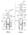
Fig. 3 is a cross sectional view of the lamp system ofFig. 1 fully inserted. -
Fig. 4 is a cross sectional view according to another preferred embodiment of the present invention illustrating the lamp system for use in a light string system. -
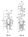
Figs. 5A and 5B are cross sectional views of the lamp system ofFig. 4 further illustrating the detail of a bypass mechanism according to a preferred embodiment. -
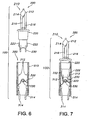
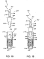
Figs. 6-8 are cross sectional views of the lamp system for use in a light string system according to another preferred embodiment of the present invention moving from non-insertion through full insertion. - To facilitate an understanding of the principles and features of the invention, it is explained hereinafter with reference to its implementation in an illustrative embodiment. In particular, the invention is described in the context of being a lamp system of a light string system.
- The invention, however, is not so limited to its use as a lamp system having a bypass. Rather, the invention can be used wherever a circuit or other system with a mechanical shunt device is needed or desired. For example, although the present invention is described as controlling flow through a light assembly when seated/unseated from a socket assembly, it will be understood that the disclosed socket assembly can be used with other insertable assemblies to contact/shunt electrical flow through the insertable assembly.
- Referring now in detail to the figures,
Fig. 1 is a partial cross-sectional view of a first preferred embodiment of a lamp system for use in a light string system. A typical light string system comprises a plurality oflamp systems 100 connected in series, wherein eachlamp system 100 has alight assembly 200 and asocket assembly 300. Thelight assembly 200 comprises alight source 210, a base 220 in communication with thelight source 210, and abypass activating system 230. Thesocket assembly 300 comprises asocket 310 adapted to receive thelight assembly 200 and abypass mechanism 320 having a first position and a second position. - The
light assembly 200 includes thelight source 210. Thelight source 210 provides light when energized. One skilled in the art can appreciate that thelight source 210 can be many types of light sources, including a light bulb, light emitting diode (LED), incandescent lamp, halogen lamp, fluorescent lamp, and the like. Preferably, thelight source 210 is a light bulb. Thelight assembly 200, and more typically, thelight bulb 210 of thelight assembly 200 has a shunt device (not shown) to keep the light string system illuminated, even if thebulb 210 bums out. - The
light source 210 can include aglobe 212 and afilament 214. Theglobe 212 is in communication with, and terminates at, thebase 220. Theglobe 212 can be made of conventional translucent or transparent material such as plastic, glass, and the like. Typically, theglobe 212 includes a hollow interior enabling protection of thefilament 214. - The
filament 214, when charged with energy, illuminates thelight source 210.Conductors 216 can be in electrical communication with thefilament 214. Theconductors 216 enable energy into thelight source 210 to illuminate thefilament 214, and as a result thelight source 210. Theconductors 216 extend down through thebase 220, wherein preferably theconductors 216 can be in communication with a pair oflead wires 222 external thebase 220. Thelead wires 222 extend through a bottom of thebase 220, and are a pair of wires wrapped around thebase 220 extending upwardly in the direction ofglobe 212, adjacent thebase 220. - The
light assembly 200 further includes thebase 220. The base 220 can be integrally formed with thelight source 210. The base 220 can be a unitary element of thelight source 210, or a separate element. Preferably, thebase 220 communicates between thelight source 210 and an associatedsocket 310, complimenting and facilitating the seating of thelight assembly 200 to thesocket 310. The base 220 can incorporate a least one ridge 226 (seeFig. 4 ) to ensure a snug fit with thesocket 310, preventing the accidental disengagement of thelight assembly 200 from thesocket assembly 300. Other mechanical means can be used with thebase 220 and thesocket assembly 300 to ensure a tight fit. - For example, the
light assembly 200 can also include a locking assembly to secure thelight assembly 200 to thesocket assembly 300. The locking assembly may be exterior, or designed within thesocket assembly 300 to fasten the connection of thelight assembly 200 to thesocket assembly 300 internally. In an exemplary embodiment, as shown inFig. 4 , the locking assembly is external and can include cooperatinglight assembly elements 224 andsocket assembly element 304. Theseelements base 220 of thelight assembly 200 can include theelement 224 that extends normal to thebase 220 and can define an aperture. On the other end of the locking assembly can be theelement 304 from thesocket 310 to be inserted into theelement 224 of thebase 220. As theelement 304 of thesocket 310 is inserted into theelement 224 of thebase 220, the locking assembly is complete. Stringent Underwriters Laboratories (UL) requirements, however, have required that lights and sockets fit tightly together, this may decrease the value of a locking mechanism in thelamp system 100. The improvement in injection molding machines now enables the production of sockets and lamp assemblies that have a tight, snug fit. - The
bypass activating system 230 preferably extends in a downward direction frombase 220 of thelight assembly 200, and is used to activate thebypass mechanism 320 of thesocket assembly 300 upon the proper seating of thelight assembly 200 therein. In one embodiment of the present invention, thebypass activating system 230 can be in a downward "V" shape (seeFig. 4 ). Alternatively, thebypass activating system 230 can be one or more extending members 232 (seeFig. 1 ). - The
socket assembly 300 comprises thesocket 310 adapted to receive thelight assembly 200. Thesocket 310 defines a cooperatively-shaped aperture to receive thebase 220 of thelight assembly 200. In a preferred embodiment, thesocket 310 is also adapted to receive the whole of thebypass activating system 230 of thelight assembly 200. Thesocket 310 can be arranged in many shapes and sizes, but as one skilled in the art will recognize, thesocket 310 should be of a shape to conveniently receive thelight assembly 200. - The
socket 310 includes a pair ofsocket terminals 312. Thesocket terminals 312 are, preferably, located on opposing inner sides of thesocket 310. Thesocket 310 further includes a pair ofterminal wires 314 extending to the exterior to allow energy to enter (and exit) thesocket 310. Eachsocket terminal 312 is, essentially, an extension of eachrespective terminal wire 314. Theterminal wire 314 extends through the bottom of thesocket 310 and is ultimately connected to an electrical source. Therefore, the electrical current is introduced into thesocket 310 by one of theterminal wires 314 and conducted either through thebypass mechanism 320 if in the first position, or throughlead wires 222 to thefilament 214 to illuminate thelight bulb 210 if in the second position. Regardless of path, the current will flow to the other of thelamp systems 100 of the light string. - The
socket assembly 300 also includes thebypass mechanism 320. Thebypass mechanism 320 includes aconductive element 322. Theconductive element 322 sits, preferably, on afulcrum 330 in thesocket 310. Theconductive element 322 has a first position and a second position. In an exemplary embodiment, thebypass mechanism 320 is positioned on a centrally-positioned fulcrum of thesocket assembly 300. - As shown in
Fig. 1 , thebypass mechanism 320 incorporates theconductive element 322, such that an electric circuit is provided from theleft terminal wire 314, through theleft socket terminal 312 acrossconductive element 322, and ultimately to theright terminal wire 314 via theright socket terminal 312. - The
conductive element 322 can be aspring mechanism 324. Thesocket 310 is dimensioned to receive the insertion of thebypass activating system 230, which forces thesingle spring 324 together, not apart, when thelight assembly 200 is inserted into thesocket 310. Thesingle spring 324 springs apart, not together, when thelight assembly 200 is removed from thelight socket 310. Thespring 324 sits about thefulcrum 330. - When the
light assembly 200 is inserted into thesocket 310, thebypass activating system 230 pushes at least one side of theconductive element 322 down, distal thesocket terminal 312 to "open" the circuit across 322. This disables the electrical connection that thebypass mechanism 320 created, and the circuit is closed via thebulb 210, not theconductive element 322. As shown inFig. 3 , both sides ofconductive element 322 are disengaged by thebypass activating system 230. In a preferred embodiment, thebypass mechanism 320 is a centrally fulcrumed spring mechanism about thefulcrum 330, and the two extendingmembers 232 push both sides of the conductingelement 322 away from thesocket terminals 312. It will be understood that other bridging mechanisms can be used beyondfulcrum 330 to support theelement 322 across thesocket 310. - The
bypass activating system 230 can have one or more pointed or rounded tips that facilitate disconnecting thebypass mechanism 320 from thesocket terminals 312. Thebypass activating system 230 disables the physical connection of thebypass mechanism 320, thereby eliminating any electrically conductive path for the electrical current to flow, other than through the insertedassembly 200. - The
bypass mechanism 320 permits the removal of one or morelight assemblies 200 of thelamp system 100, while maintaining the lighting of the remaining lights of a light string system. When alight assembly 200 is missing from thesocket 310, thebypass mechanism 320 creates a short circuit, and therefore enables current flow to keepother lamp systems 100 with energy at eachsocket 310. Eachsocket 310 can have a single currentcarrying bypass mechanism 320, which pushes away from thesocket terminal 312 when thebypass activating system 230 engages thebypass mechanism 320 thereby breaking electrical continuity across thebypass mechanism 320. When thebase 220 of thelight assembly 200 is fully engaged in thesocket 310, thelead wires 222 extending from the base 220 will make electrical contact with thesocket terminals 312 completing the electrical circuit. When thelight assembly 200 is removed, thebypass mechanism 320 opens again and makes contact with thesocket terminals 312, maintaining the electrical connection. - The
bypass mechanism 320 has a first position and a second position. The first position bypasses energy flow when alight assembly 200 is not properly seated in the socket 310 (Figs. 1-2 ). In the first position, thebypass mechanism 320 extends to make contact with the sides of thesocket 310, thesocket terminal 312. As a result, an electrical circuit is created, or a short circuit is formed. This situation arises when thelight assembly 200 is missing from thesocket 310. The second position enables energy to flow through thelight source 210 to illuminate it (Fig. 3 ). In the second position, thebypass mechanism 320 is removed from electrical communication from at least one side of the socket 310 (at least one socket terminal 312). The electrical circuit through thebypass mechanism 320 is disconnected, or an open circuit is formed. This situation typically arises when alight assembly 200 is fully inserted into thesocket 310. For instance, thebypass activating system 230 pushes thebypass mechanism 320 together when thelight assembly 200 is being seated in thesocket 310; and thebypass mechanism 320 pushes apart when thelight source 210 is being removed from thesocket 310. -
Figs. 1-3 are partial cross sectional views of a preferred embodiment of thelamp system 100 illustrating thelight assembly 200 being inserted into and fully seated in thesocket 310. As thelight assembly 200 is inserted into thesocket 310, electrical current flowing through thebypass mechanism 320 is interrupted. When physical contact betweenbypass mechanism 320 is broken by thebypass activating system 230, electrical current flow is then enabled to flow through thelead wires 222 and up through theconductors 216 to illuminate thelight source 210. The current then resumes flowing out through the opposite side of theconductor 216 and down through theother lead wire 222, passing through theother terminal wire 314 until it exits thatparticular lamp system 100. Aflange 240 engagessocket 310 whenlight assembly 200 is fully seated. -
Fig. 4 illustrates another preferred embodiment of thelamp system 100. Thelamp system 100 includes thebypass activating system 230 shown having an upside down "V" shape. The shape - of thebypass activating system 230 enables contact with thebypass mechanism 320, and further permits the switching of thebypass mechanism 320 from the first position to the second position. Additionally, inFig. 4 , thebypass mechanism 320 is positioned upon thefulcrum 330. -
Figs. 5A and 5B illustrates a cross sectional view of a lamp for use in alamp system 100 further illustrating the detail of thebypass mechanism 320. Since thebypass mechanism 320 is preferably is aspring 324, one skilled in the art will appreciate describing thebypass mechanism 320 in terms of aspring 324. Thespring 324 can be a single spring that is connected to thesocket 310 with afulcrum 330 in thesocket 310. Providing asocket 310 with a centrally located,single fulcrum 330 enables easy manufacturability. One skilled in the art can appreciate that the way thespring 324 is seated in thesocket 310 can be by a pivot, hinge, pin, and the like, and need not be centrally located nor must theelement 322 be a single element. It can include two or more elements that can be electrically communicative through thefulcrum 330. - The
spring 324 can be of the length to span the length of the diameter of thesocket 310. In this arrangement, thespring 324 would create the short circuit by contacting thesocket terminals 312. In alternative embodiments, thespring 324 can be in connection with a conductor (not shown) to span the length of the diameter of thesocket 310. -
Figs. 6-8 illustrate another preferred embodiment of the present invention. InFigs. 6-8 thebypass activating system 230 strikes only one branch of thebypass mechanism 320. In this arrangement, thebypass mechanism 320 creates an open circuit by having thebypass activating system 230 to strike only one side of thebypass mechanism 320. Thebypass activating system 230, as depicted, includes two structures extending from thebase 220 of thelight assembly 200. Consequently, it will be understood by one in the art that thebypass activating system 230 can include a single extendingmember 232 extending from thebase 220. Thebypass mechanism 320 still includes a first position and a second position. - In this embodiment, the
left side terminal 314 is always in electrical communication with thebypass mechanism 320, only the right side of thebypass mechanism 320 is activated between the first and second positions by thebypass activating system 230. - While the invention has been disclosed in its preferred forms, it will be apparent to those skilled in the art that many modifications, additions, and deletions can be made therein.
Claims (5)
- A lamp system (100) comprising:a light assembly (200); anda socket assembly (300) dimensioned to receive via insertion the light assembly (200), the socket assembly (300) incorporating a bypass mechanism (320) moveable between a first position and a second position,wherein in the first position current flow is bypassed from the light assembly (200), and across the socket assembly (300),wherein in the second position, current flow is directed through the light assembly (200),characterized in that insertion of the light assembly (200) into the socket assembly (300) moves the bypass mechanism (320) together and away from internal opposing side walls of the socket assembly (300), and into the second position, andin that removal of the light assembly (200) from the socket assembly (300) causes the bypass mechanism (320) to spring apart and towards the internal opposing side walls of the socket assembly (300), and into the first position.
- The lamp system (100) of Claim 1, the socket assembly (300) having a pair of socket terminals (312) therein, wherein the opposing side walls are in electrical communication with the pair of socket terminals (312).
- The lamp system (100) of Claim 2, the light assembly (200) including a light source (210), a base (220) in communication with the light source (210), and a bypass activating system (230) extending downwardly from the base (220).
- The lamp system (100) of Claim 3, the bypass mechanism (320) moveable between the first position and the second position by the bypass activating system (230) of the light assembly (200), the bypass activating system (230) moves at least one end of the bypass mechanism (320) distant one of the socket terminals (312), disengaging the electrical communication of the pair of socket terminals (312) with the bypass mechanism (320).
- The lamp system (100) of Claim 2, the bypass mechanism (320) including a centrally-positioned fulcrum (330) and spring mechanism (324), the spring mechanism (324) stabilized about the fulcrum (330).
Priority Applications (1)
| Application Number | Priority Date | Filing Date | Title |
|---|---|---|---|
| EP09015630A EP2163818B1 (en) | 2005-06-02 | 2006-06-02 | Light string system |
Applications Claiming Priority (4)
| Application Number | Priority Date | Filing Date | Title |
|---|---|---|---|
| US68655005P | 2005-06-02 | 2005-06-02 | |
| US21446005A | 2005-08-29 | 2005-08-29 | |
| US73450705P | 2005-11-08 | 2005-11-08 | |
| PCT/US2006/021242 WO2006130751A1 (en) | 2005-06-02 | 2006-06-02 | Light string system |
Related Child Applications (1)
| Application Number | Title | Priority Date | Filing Date |
|---|---|---|---|
| EP09015630.8 Division-Into | 2009-12-17 |
Publications (3)
| Publication Number | Publication Date |
|---|---|
| EP1920186A1 EP1920186A1 (en) | 2008-05-14 |
| EP1920186A4 EP1920186A4 (en) | 2008-11-26 |
| EP1920186B1 true EP1920186B1 (en) | 2010-03-10 |
Family
ID=37481996
Family Applications (2)
| Application Number | Title | Priority Date | Filing Date |
|---|---|---|---|
| EP09015630A Active EP2163818B1 (en) | 2005-06-02 | 2006-06-02 | Light string system |
| EP06760620A Active EP1920186B1 (en) | 2005-06-02 | 2006-06-02 | Light string system |
Family Applications Before (1)
| Application Number | Title | Priority Date | Filing Date |
|---|---|---|---|
| EP09015630A Active EP2163818B1 (en) | 2005-06-02 | 2006-06-02 | Light string system |
Country Status (5)
| Country | Link |
|---|---|
| US (3) | US7264392B2 (en) |
| EP (2) | EP2163818B1 (en) |
| AT (1) | ATE460620T1 (en) |
| DE (1) | DE602006012850D1 (en) |
| WO (1) | WO2006130751A1 (en) |
Families Citing this family (63)
| Publication number | Priority date | Publication date | Assignee | Title |
|---|---|---|---|---|
| ATE460620T1 (en) | 2005-06-02 | 2010-03-15 | Gp Ltd | LIGHT CHAIN SYSTEM |
| US7399110B2 (en) * | 2005-11-28 | 2008-07-15 | Cindex Holdings Limited (A Hong Kong Corporation) | Decorative light system |
| US20070133205A1 (en) * | 2005-12-13 | 2007-06-14 | Cindex Holdings Limited (A Hong Kong Corporation) | Dead wire housing assembly |
| US7819552B2 (en) | 2006-10-25 | 2010-10-26 | Seasonal Specialties Llc | Mechanical bypass light unit |
| CN200979133Y (en) * | 2006-10-25 | 2007-11-21 | 陈琦 | Decorating lamp |
| US7967619B2 (en) * | 2006-10-25 | 2011-06-28 | Zheng Dianqing | Light string with improved shunt system |
| CN201246626Y (en) * | 2008-08-18 | 2009-05-27 | 郑靛青 | Decorating lamp |
| US7253556B1 (en) | 2006-12-08 | 2007-08-07 | Tech Patent Licensing, Llc | Light string socket with mechanical shunt |
| US7771109B2 (en) * | 2007-02-07 | 2010-08-10 | Jetmax Industrial Ltd. | Lamp for light string |
| US20080186740A1 (en) * | 2007-02-07 | 2008-08-07 | Mike Huang | Connecting assembly in light strings to maintain electrical connection |
| US20080239758A1 (en) * | 2007-03-26 | 2008-10-02 | Kai Kong Ng | Snap-in lamp for an electric light string |
| US20080299817A1 (en) * | 2007-05-31 | 2008-12-04 | Chih-Ping Liu | Structure of lamp socket in lamp string |
| CN101319757B (en) * | 2007-06-08 | 2011-01-12 | 云梦云曦灯饰制品有限公司 | Bulb system |
| US7484995B2 (en) * | 2007-06-11 | 2009-02-03 | Hui Dong Xie Qun Lighting Manufacturing | Lamp system |
| US7554266B1 (en) | 2007-09-11 | 2009-06-30 | Willis Electric Co., Ltd. | Mechanical shunt for use in a socket in a string of lights |
| TWI355098B (en) * | 2007-09-21 | 2011-12-21 | Cheng Kung Capital Llc | Led lamp waterproof module |
| US7943211B2 (en) * | 2007-12-06 | 2011-05-17 | Willis Electric Co., Ltd. | Three dimensional displays having deformable constructions |
| US20090190359A1 (en) * | 2008-01-28 | 2009-07-30 | Cindex Holdings Limited (A Hong Kong Corporation) | Led light string system |
| GB0809610D0 (en) * | 2008-05-28 | 2008-07-02 | Miller Andrew | Transformer |
| US7626131B1 (en) | 2008-06-03 | 2009-12-01 | Tech Patent Licensing, Llc | Mechanical shunt for light string socket with self-cleaning feature |
| US7633024B1 (en) * | 2008-06-03 | 2009-12-15 | Tech Patent Licensing, Llc | Push rod shunt for light string sockets |
| US7629544B1 (en) * | 2008-06-03 | 2009-12-08 | Tech Patent Licensing, Llc | Asymmetric spring coil shunt for light string socket |
| US7626321B1 (en) | 2008-06-03 | 2009-12-01 | Tech Patent Licensing, Llc | Spring coil shunt for light string socket |
| US7453194B1 (en) | 2008-06-05 | 2008-11-18 | Gibboney James W | Mechanical shunt for use in the sockets of a string of lights |
| US7557497B1 (en) | 2008-09-22 | 2009-07-07 | Tech Patent Licensing, Llc | Asymmetric mechanical shunt switch for use in a socket of a string of lights |
| US7980871B2 (en) * | 2008-10-20 | 2011-07-19 | Polygroup Macau Limited (Bvi) | Light string system |
| US20100289415A1 (en) * | 2009-05-18 | 2010-11-18 | Johnny Chen | Energy efficient decorative lighting |
| US10993572B2 (en) | 2009-07-14 | 2021-05-04 | Belgravia Wood Limited | Power pole for artificial tree apparatus with axial electrical connectors |
| US9833098B2 (en) | 2009-07-14 | 2017-12-05 | Loominocity, Inc. | Architecture for routing multi-channel commands via a tree column |
| US11096511B2 (en) | 2009-07-14 | 2021-08-24 | Belgravia Wood Limited | Power pole for artificial tree apparatus with axial electrical connectors |
| US20110085327A1 (en) * | 2009-10-14 | 2011-04-14 | Johnny Chen | Decorative light display with LEDs |
| WO2011069286A1 (en) * | 2009-12-08 | 2011-06-16 | 台山市国际电器厂有限公司 | Decorative lamp strip for preventing broken circuit and overcurrent |
| US8235737B2 (en) | 2009-12-09 | 2012-08-07 | Polygroup Macau Limited (Bvi) | Light string system |
| CN201811064U (en) * | 2010-07-27 | 2011-04-27 | 张冰 | Christmas lamp |
| US8454186B2 (en) | 2010-09-23 | 2013-06-04 | Willis Electric Co., Ltd. | Modular lighted tree with trunk electical connectors |
| US8298633B1 (en) | 2011-05-20 | 2012-10-30 | Willis Electric Co., Ltd. | Multi-positional, locking artificial tree trunk |
| JP2013037989A (en) * | 2011-08-10 | 2013-02-21 | Yazaki Corp | Socket |
| US8863416B2 (en) | 2011-10-28 | 2014-10-21 | Polygroup Macau Limited (Bvi) | Powered tree construction |
| US8569960B2 (en) | 2011-11-14 | 2013-10-29 | Willis Electric Co., Ltd | Conformal power adapter for lighted artificial tree |
| US9157587B2 (en) | 2011-11-14 | 2015-10-13 | Willis Electric Co., Ltd. | Conformal power adapter for lighted artificial tree |
| US8876321B2 (en) | 2011-12-09 | 2014-11-04 | Willis Electric Co., Ltd. | Modular lighted artificial tree |
| US9572446B2 (en) | 2012-05-08 | 2017-02-21 | Willis Electric Co., Ltd. | Modular tree with locking trunk and locking electrical connectors |
| US10206530B2 (en) | 2012-05-08 | 2019-02-19 | Willis Electric Co., Ltd. | Modular tree with locking trunk |
| US9044056B2 (en) | 2012-05-08 | 2015-06-02 | Willis Electric Co., Ltd. | Modular tree with electrical connector |
| US9179793B2 (en) | 2012-05-08 | 2015-11-10 | Willis Electric Co., Ltd. | Modular tree with rotation-lock electrical connectors |
| CN203099480U (en) * | 2013-02-04 | 2013-07-31 | 韩厚华 | Christmas lamp |
| US9439528B2 (en) | 2013-03-13 | 2016-09-13 | Willis Electric Co., Ltd. | Modular tree with locking trunk and locking electrical connectors |
| US9671074B2 (en) | 2013-03-13 | 2017-06-06 | Willis Electric Co., Ltd. | Modular tree with trunk connectors |
| US11306881B2 (en) | 2013-09-13 | 2022-04-19 | Willis Electric Co., Ltd. | Tangle-resistant decorative lighting assembly |
| US9140438B2 (en) | 2013-09-13 | 2015-09-22 | Willis Electric Co., Ltd. | Decorative lighting with reinforced wiring |
| US9157588B2 (en) | 2013-09-13 | 2015-10-13 | Willis Electric Co., Ltd | Decorative lighting with reinforced wiring |
| US9894949B1 (en) | 2013-11-27 | 2018-02-20 | Willis Electric Co., Ltd. | Lighted artificial tree with improved electrical connections |
| US8870404B1 (en) | 2013-12-03 | 2014-10-28 | Willis Electric Co., Ltd. | Dual-voltage lighted artificial tree |
| US20150211726A1 (en) * | 2014-01-27 | 2015-07-30 | Yueh-Feng Wu Lee | Fully-waterproof and maintainable led christmas light |
| US9883566B1 (en) | 2014-05-01 | 2018-01-30 | Willis Electric Co., Ltd. | Control of modular lighted artificial trees |
| US9839315B2 (en) | 2015-03-27 | 2017-12-12 | Polygroup Macau Limited (Bvi) | Multi-wire quick assemble tree |
| US9444173B1 (en) * | 2015-06-04 | 2016-09-13 | Ford Global Technologies, Llc | Retractile socket adapter for 12V outlet |
| CA2946387A1 (en) | 2015-10-26 | 2017-04-26 | Willis Electric Co., Ltd. | Tangle-resistant decorative lighting assembly |
| US9907136B2 (en) | 2016-03-04 | 2018-02-27 | Polygroup Macau Limited (Bv) | Variable multi-color LED light string and controller for an artificial tree |
| US10615547B2 (en) * | 2016-09-08 | 2020-04-07 | Raytheon Company | Electrical device with shunt, and receptacle |
| US20180135843A1 (en) * | 2016-11-11 | 2018-05-17 | Xenio Corporation | Cartridge and socket for light fixtures |
| US10441014B1 (en) | 2017-01-03 | 2019-10-15 | Willis Electric Co., Ltd. | Artificial tree having multiple tree portions with electrical connectors secured therein |
| US10683974B1 (en) | 2017-12-11 | 2020-06-16 | Willis Electric Co., Ltd. | Decorative lighting control |
Family Cites Families (74)
| Publication number | Priority date | Publication date | Assignee | Title |
|---|---|---|---|---|
| US932129A (en) | 1908-09-11 | 1909-08-24 | George M Hughes | Door-hinge. |
| US1536332A (en) * | 1924-11-22 | 1925-05-05 | Monowatt Electric Imp Co Inc | Lamp socket for christmas-tree lighting |
| US2025564A (en) | 1932-12-24 | 1935-12-24 | Gen Electric | Electrical socket |
| US2576363A (en) | 1947-05-17 | 1951-11-27 | Westinghouse Electric Corp | Socket for series lamps and string thereof |
| US3359523A (en) | 1966-01-26 | 1967-12-19 | Lou Shih-Woo | Shunt device |
| US3915536A (en) * | 1972-02-23 | 1975-10-28 | Hellzen Bertil | Holder for an electric lamp |
| JPS5043092A (en) | 1973-08-20 | 1975-04-18 | ||
| FR2536594A1 (en) | 1982-11-22 | 1984-05-25 | Droguet Int | ELECTRICAL CONNECTOR AND SOCKET IN PARTICULAR FOR ELECTRIC GUIRANDS |
| DE8327191U1 (en) | 1983-09-22 | 1983-12-29 | Schroff Gmbh, 7541 Straubenhardt | Guide rail with fastening device for a connector strip |
| US4727449A (en) | 1986-10-01 | 1988-02-23 | Chiu Technical Corporation | Filament bypass circuit |
| JPS63164198A (en) | 1986-12-25 | 1988-07-07 | 三菱電機株式会社 | Electric source switch of personal computer |
| US4969071A (en) | 1988-06-13 | 1990-11-06 | U.S. Philips Corporation | Illumination set |
| US4894019A (en) * | 1988-06-16 | 1990-01-16 | Delta Systems, Inc. | Torsion spring shorting connector |
| JP2660562B2 (en) | 1988-10-12 | 1997-10-08 | 日本信号株式会社 | Lamp disconnection detection device |
| US4991071A (en) | 1989-04-14 | 1991-02-05 | Noma International, Inc. | Light string set |
| WO1991010093A1 (en) | 1990-01-05 | 1991-07-11 | Ahroni Joseph M | Improved chaser decorative light set and miniature light units |
| US5139393A (en) * | 1990-02-13 | 1992-08-18 | Hale Fire Pump Company | Thermal relief valve |
| JP3075804B2 (en) | 1990-08-09 | 2000-08-14 | 森山産業株式会社 | Series lighting device |
| US5071362A (en) * | 1990-10-12 | 1991-12-10 | Augat Inc. | Self-operative electrical shunting contact and method for forming |
| US5139343A (en) * | 1992-01-14 | 1992-08-18 | Lin Wen Hsiung | Lamp holder with switch means |
| DE9207136U1 (en) | 1992-05-26 | 1992-08-06 | Lin, Wen-Hsiung, Panchiao, Taipeh, Tw | |
| JPH0641119A (en) | 1992-07-24 | 1994-02-15 | Mitsui Toatsu Chem Inc | Triazinylthioquinoline derivative and its production and agricultural/horticultural germicide with the same as active ingredient |
| US5281158A (en) | 1993-01-11 | 1994-01-25 | Lin Wen Hsiung | Light socket and socket adapter |
| JPH0787691A (en) | 1993-09-14 | 1995-03-31 | Matsushita Electric Works Ltd | Non-connected feeder system |
| US5453664A (en) | 1994-02-01 | 1995-09-26 | Harris; Geoffrey H. | Light string with improved shunt system |
| US5455484A (en) | 1994-09-16 | 1995-10-03 | Matsushita Electric Works R&D Laboratory, Inc. | Adapter for simultaneously powering multiple compact fluorescent lamps utilizing an electronic ballast circuit |
| US5513081A (en) | 1995-04-27 | 1996-04-30 | Byers; Thomas L. | Multiple light installation and storage system |
| US7086758B2 (en) | 1995-06-26 | 2006-08-08 | Jlj, Inc. | Series connected light string with filament shunting |
| US7178961B2 (en) | 1995-06-26 | 2007-02-20 | Jlj, Inc. | Voltage regulated light string |
| US7279809B2 (en) | 1995-06-26 | 2007-10-09 | Jlj, Inc. | Christmas light string with single Zener shunts |
| US20020047594A1 (en) | 1995-06-26 | 2002-04-25 | Janning John L. | Series connected light string with filament shunting |
| CN1145242A (en) | 1996-06-17 | 1997-03-19 | 杨景照 | Extornal-use burn and scald medicine |
| US5702262A (en) | 1996-10-04 | 1997-12-30 | Trompeter Electronics, Inc. | Connector assembly |
| US5994845A (en) | 1997-04-24 | 1999-11-30 | Ventur Research & Development Inc. | Electrical light socket |
| JPH11185978A (en) | 1997-12-24 | 1999-07-09 | Koito Ind Ltd | Lighting system |
| JPH11288252A (en) | 1998-04-01 | 1999-10-19 | Daichu Denshi:Kk | Lighting device and extended display device using this device |
| US6053774A (en) | 1998-10-28 | 2000-04-25 | Lin; Fong Shi | Miniature light bulb socket structure having an insert to keep wire terminals separate |
| US6203169B1 (en) * | 1999-06-25 | 2001-03-20 | Osram Sylvania Inc. | Lamp and method of producing same |
| US6283797B1 (en) | 1999-07-30 | 2001-09-04 | Jeng-Shyong Wu | Structure of a lamp base |
| JP2001076507A (en) | 1999-09-03 | 2001-03-23 | Hongo Shizuko | Decorative electric bulb and multi-lamp luminaire with it |
| US6203166B1 (en) | 1999-10-12 | 2001-03-20 | Gary Products Group, Inc. | Reconfigurable decorative star apparatus |
| US6630773B1 (en) | 1999-12-15 | 2003-10-07 | Shining Blick Enterprises Co., Ltd. | Assembling structure for lamp string with fully enveloped bulbs |
| US6224415B1 (en) | 2000-02-11 | 2001-05-01 | James W Gibboney, Jr. | Locking light socket and light |
| US6257740B1 (en) | 2000-02-11 | 2001-07-10 | James W Gibboney, Jr. | Lamp for use in light strings |
| CN2458789Y (en) | 2000-11-13 | 2001-11-07 | 潘文芳 | Current conducting device for lamp string lamp bulb set |
| CA2441278C (en) | 2001-03-19 | 2009-12-29 | Integrated Power Components, Inc. | Decorative light string having shunt repair device |
| JP2003208993A (en) | 2002-01-11 | 2003-07-25 | Toyoda Gosei Co Ltd | Led illumination equipment |
| US6533437B1 (en) * | 2002-01-29 | 2003-03-18 | Joseph M. Ahroni | Apparatus, systems, and methods for maintaining power to a light string having light units arranged in series |
| US6755552B2 (en) * | 2002-04-23 | 2004-06-29 | Hung-Wen Lee | Conductive plate of a bulb assembly |
| US6650065B1 (en) | 2002-05-22 | 2003-11-18 | Whiter Shieh | Decorative bulb unit with filament shunt mounted in bulb socket thereof |
| US6774549B2 (en) | 2002-08-21 | 2004-08-10 | Ching-Yen Tsai | Lamp structure of lamp string |
| CN2583839Y (en) | 2002-11-19 | 2003-10-29 | 谢怀棠 | Elastic contact structure of current diverter for christmas lamp socket |
| US6805463B2 (en) * | 2002-12-03 | 2004-10-19 | Whiter Shieh | Shunt element contacting structure for decorative lamp holder |
| US6806656B2 (en) | 2002-12-16 | 2004-10-19 | Sienna Llc | Fuse bulb twinkle light set |
| US6713971B1 (en) | 2003-01-09 | 2004-03-30 | Pi-Chu Wong | Lamp string with an open-circuit-proof structure |
| CN2595018Y (en) | 2003-01-09 | 2003-12-24 | 翁碧珠 | Arrangement structure for preventing light series from circuit break |
| CN2702165Y (en) | 2004-05-21 | 2005-05-25 | 嘉智集团有限公司 | Series lamp string and lamp-socket assembly thereof |
| US20050286267A1 (en) * | 2004-06-29 | 2005-12-29 | Wang Jung K | Auto-contact bulb assembly |
| US7186017B2 (en) * | 2005-01-05 | 2007-03-06 | Cheng-Ju Kuo | Backstop socket structure for lamp string |
| ATE460620T1 (en) | 2005-06-02 | 2010-03-15 | Gp Ltd | LIGHT CHAIN SYSTEM |
| US7473024B2 (en) | 2005-08-30 | 2009-01-06 | Ventur Research & Development Corp. | Light strings including standard socket and longer-length non-standard keyed socket |
| US20070159109A1 (en) | 2006-01-09 | 2007-07-12 | Gibboney James W | String of lights with voltage regulation |
| US7963670B2 (en) | 2006-07-31 | 2011-06-21 | 1 Energy Solutions, Inc. | Bypass components in series wired LED light strings |
| US7819552B2 (en) | 2006-10-25 | 2010-10-26 | Seasonal Specialties Llc | Mechanical bypass light unit |
| US7253556B1 (en) * | 2006-12-08 | 2007-08-07 | Tech Patent Licensing, Llc | Light string socket with mechanical shunt |
| US20080186740A1 (en) * | 2007-02-07 | 2008-08-07 | Mike Huang | Connecting assembly in light strings to maintain electrical connection |
| US20080239758A1 (en) | 2007-03-26 | 2008-10-02 | Kai Kong Ng | Snap-in lamp for an electric light string |
| US20080258630A1 (en) | 2007-04-20 | 2008-10-23 | Collins Matthew D | Light String Lamp Bypass Device |
| US7484995B2 (en) * | 2007-06-11 | 2009-02-03 | Hui Dong Xie Qun Lighting Manufacturing | Lamp system |
| US7554266B1 (en) | 2007-09-11 | 2009-06-30 | Willis Electric Co., Ltd. | Mechanical shunt for use in a socket in a string of lights |
| US20090190359A1 (en) | 2008-01-28 | 2009-07-30 | Cindex Holdings Limited (A Hong Kong Corporation) | Led light string system |
| US7453194B1 (en) | 2008-06-05 | 2008-11-18 | Gibboney James W | Mechanical shunt for use in the sockets of a string of lights |
| US7557497B1 (en) | 2008-09-22 | 2009-07-07 | Tech Patent Licensing, Llc | Asymmetric mechanical shunt switch for use in a socket of a string of lights |
| US7980871B2 (en) | 2008-10-20 | 2011-07-19 | Polygroup Macau Limited (Bvi) | Light string system |
-
2006
- 2006-06-02 AT AT06760620T patent/ATE460620T1/en not_active IP Right Cessation
- 2006-06-02 WO PCT/US2006/021242 patent/WO2006130751A1/en active Application Filing
- 2006-06-02 DE DE602006012850T patent/DE602006012850D1/en not_active Expired - Fee Related
- 2006-06-02 EP EP09015630A patent/EP2163818B1/en active Active
- 2006-06-02 EP EP06760620A patent/EP1920186B1/en active Active
- 2006-06-23 US US11/473,504 patent/US7264392B2/en active Active
-
2007
- 2007-09-04 US US11/849,423 patent/US7581870B2/en active Active
-
2009
- 2009-07-17 US US12/505,067 patent/US8047700B2/en active Active
Also Published As
| Publication number | Publication date |
|---|---|
| EP2163818B1 (en) | 2012-11-21 |
| EP2163818A3 (en) | 2010-03-31 |
| ATE460620T1 (en) | 2010-03-15 |
| WO2006130751A1 (en) | 2006-12-07 |
| DE602006012850D1 (en) | 2010-04-22 |
| EP2163818A2 (en) | 2010-03-17 |
| US20070297196A1 (en) | 2007-12-27 |
| US20060274556A1 (en) | 2006-12-07 |
| US7581870B2 (en) | 2009-09-01 |
| US7264392B2 (en) | 2007-09-04 |
| EP1920186A4 (en) | 2008-11-26 |
| US20090279325A1 (en) | 2009-11-12 |
| EP1920186A1 (en) | 2008-05-14 |
| US8047700B2 (en) | 2011-11-01 |
Similar Documents
| Publication | Publication Date | Title |
|---|---|---|
| EP1920186B1 (en) | Light string system | |
| US7980871B2 (en) | Light string system | |
| US6257740B1 (en) | Lamp for use in light strings | |
| US8753135B2 (en) | Light string system | |
| US6609814B2 (en) | Apparatus, systems, and methods for maintaining power to a light string having light units arranged in series | |
| US9341329B2 (en) | Mechanical bypass light unit | |
| US5139343A (en) | Lamp holder with switch means | |
| US20040105270A1 (en) | Shunt element contacting structure for decorative lamp holder | |
| US7557497B1 (en) | Asymmetric mechanical shunt switch for use in a socket of a string of lights | |
| US7740503B1 (en) | Current non-interruption bulb socket of lamp string | |
| US7626321B1 (en) | Spring coil shunt for light string socket | |
| US7965025B2 (en) | Light string with improved shunt system | |
| US6476559B2 (en) | Ceremonial luminary and associated process | |
| GB2071837A (en) | A rope light | |
| US5880663A (en) | Bridge switch | |
| US1734162A (en) | Electric-lamp socket |
Legal Events
| Date | Code | Title | Description |
|---|---|---|---|
| PUAI | Public reference made under article 153(3) epc to a published international application that has entered the european phase |
Free format text: ORIGINAL CODE: 0009012 |
|
| 17P | Request for examination filed |
Effective date: 20080103 |
|
| AK | Designated contracting states |
Kind code of ref document: A1 Designated state(s): AT BE BG CH CY CZ DE DK EE ES FI FR GB GR HU IE IS IT LI LT LU LV MC NL PL PT RO SE SI SK TR |
|
| DAX | Request for extension of the european patent (deleted) | ||
| A4 | Supplementary search report drawn up and despatched |
Effective date: 20081023 |
|
| GRAP | Despatch of communication of intention to grant a patent |
Free format text: ORIGINAL CODE: EPIDOSNIGR1 |
|
| GRAS | Grant fee paid |
Free format text: ORIGINAL CODE: EPIDOSNIGR3 |
|
| GRAA | (expected) grant |
Free format text: ORIGINAL CODE: 0009210 |
|
| AK | Designated contracting states |
Kind code of ref document: B1 Designated state(s): AT BE BG CH CY CZ DE DK EE ES FI FR GB GR HU IE IS IT LI LT LU LV MC NL PL PT RO SE SI SK TR |
|
| REG | Reference to a national code |
Ref country code: GB Ref legal event code: FG4D |
|
| REG | Reference to a national code |
Ref country code: CH Ref legal event code: EP |
|
| REG | Reference to a national code |
Ref country code: IE Ref legal event code: FG4D |
|
| REF | Corresponds to: |
Ref document number: 602006012850 Country of ref document: DE Date of ref document: 20100422 Kind code of ref document: P |
|
| REG | Reference to a national code |
Ref country code: NL Ref legal event code: VDEP Effective date: 20100310 |
|
| PG25 | Lapsed in a contracting state [announced via postgrant information from national office to epo] |
Ref country code: LT Free format text: LAPSE BECAUSE OF FAILURE TO SUBMIT A TRANSLATION OF THE DESCRIPTION OR TO PAY THE FEE WITHIN THE PRESCRIBED TIME-LIMIT Effective date: 20100310 |
|
| LTIE | Lt: invalidation of european patent or patent extension |
Effective date: 20100310 |
|
| PG25 | Lapsed in a contracting state [announced via postgrant information from national office to epo] |
Ref country code: FI Free format text: LAPSE BECAUSE OF FAILURE TO SUBMIT A TRANSLATION OF THE DESCRIPTION OR TO PAY THE FEE WITHIN THE PRESCRIBED TIME-LIMIT Effective date: 20100310 Ref country code: AT Free format text: LAPSE BECAUSE OF FAILURE TO SUBMIT A TRANSLATION OF THE DESCRIPTION OR TO PAY THE FEE WITHIN THE PRESCRIBED TIME-LIMIT Effective date: 20100310 Ref country code: LV Free format text: LAPSE BECAUSE OF FAILURE TO SUBMIT A TRANSLATION OF THE DESCRIPTION OR TO PAY THE FEE WITHIN THE PRESCRIBED TIME-LIMIT Effective date: 20100310 Ref country code: SI Free format text: LAPSE BECAUSE OF FAILURE TO SUBMIT A TRANSLATION OF THE DESCRIPTION OR TO PAY THE FEE WITHIN THE PRESCRIBED TIME-LIMIT Effective date: 20100310 Ref country code: PL Free format text: LAPSE BECAUSE OF FAILURE TO SUBMIT A TRANSLATION OF THE DESCRIPTION OR TO PAY THE FEE WITHIN THE PRESCRIBED TIME-LIMIT Effective date: 20100310 |
|
| PG25 | Lapsed in a contracting state [announced via postgrant information from national office to epo] |
Ref country code: SE Free format text: LAPSE BECAUSE OF FAILURE TO SUBMIT A TRANSLATION OF THE DESCRIPTION OR TO PAY THE FEE WITHIN THE PRESCRIBED TIME-LIMIT Effective date: 20100310 Ref country code: RO Free format text: LAPSE BECAUSE OF FAILURE TO SUBMIT A TRANSLATION OF THE DESCRIPTION OR TO PAY THE FEE WITHIN THE PRESCRIBED TIME-LIMIT Effective date: 20100310 Ref country code: NL Free format text: LAPSE BECAUSE OF FAILURE TO SUBMIT A TRANSLATION OF THE DESCRIPTION OR TO PAY THE FEE WITHIN THE PRESCRIBED TIME-LIMIT Effective date: 20100310 Ref country code: GR Free format text: LAPSE BECAUSE OF FAILURE TO SUBMIT A TRANSLATION OF THE DESCRIPTION OR TO PAY THE FEE WITHIN THE PRESCRIBED TIME-LIMIT Effective date: 20100611 Ref country code: ES Free format text: LAPSE BECAUSE OF FAILURE TO SUBMIT A TRANSLATION OF THE DESCRIPTION OR TO PAY THE FEE WITHIN THE PRESCRIBED TIME-LIMIT Effective date: 20100621 Ref country code: BE Free format text: LAPSE BECAUSE OF FAILURE TO SUBMIT A TRANSLATION OF THE DESCRIPTION OR TO PAY THE FEE WITHIN THE PRESCRIBED TIME-LIMIT Effective date: 20100310 Ref country code: CY Free format text: LAPSE BECAUSE OF FAILURE TO SUBMIT A TRANSLATION OF THE DESCRIPTION OR TO PAY THE FEE WITHIN THE PRESCRIBED TIME-LIMIT Effective date: 20100310 Ref country code: EE Free format text: LAPSE BECAUSE OF FAILURE TO SUBMIT A TRANSLATION OF THE DESCRIPTION OR TO PAY THE FEE WITHIN THE PRESCRIBED TIME-LIMIT Effective date: 20100310 |
|
| PG25 | Lapsed in a contracting state [announced via postgrant information from national office to epo] |
Ref country code: IS Free format text: LAPSE BECAUSE OF FAILURE TO SUBMIT A TRANSLATION OF THE DESCRIPTION OR TO PAY THE FEE WITHIN THE PRESCRIBED TIME-LIMIT Effective date: 20100710 Ref country code: SK Free format text: LAPSE BECAUSE OF FAILURE TO SUBMIT A TRANSLATION OF THE DESCRIPTION OR TO PAY THE FEE WITHIN THE PRESCRIBED TIME-LIMIT Effective date: 20100310 Ref country code: BG Free format text: LAPSE BECAUSE OF FAILURE TO SUBMIT A TRANSLATION OF THE DESCRIPTION OR TO PAY THE FEE WITHIN THE PRESCRIBED TIME-LIMIT Effective date: 20100610 Ref country code: CZ Free format text: LAPSE BECAUSE OF FAILURE TO SUBMIT A TRANSLATION OF THE DESCRIPTION OR TO PAY THE FEE WITHIN THE PRESCRIBED TIME-LIMIT Effective date: 20100310 |
|
| PLBE | No opposition filed within time limit |
Free format text: ORIGINAL CODE: 0009261 |
|
| STAA | Information on the status of an ep patent application or granted ep patent |
Free format text: STATUS: NO OPPOSITION FILED WITHIN TIME LIMIT |
|
| PG25 | Lapsed in a contracting state [announced via postgrant information from national office to epo] |
Ref country code: DK Free format text: LAPSE BECAUSE OF FAILURE TO SUBMIT A TRANSLATION OF THE DESCRIPTION OR TO PAY THE FEE WITHIN THE PRESCRIBED TIME-LIMIT Effective date: 20100310 Ref country code: MC Free format text: LAPSE BECAUSE OF NON-PAYMENT OF DUE FEES Effective date: 20100630 Ref country code: PT Free format text: LAPSE BECAUSE OF FAILURE TO SUBMIT A TRANSLATION OF THE DESCRIPTION OR TO PAY THE FEE WITHIN THE PRESCRIBED TIME-LIMIT Effective date: 20100712 |
|
| REG | Reference to a national code |
Ref country code: CH Ref legal event code: PL |
|
| 26N | No opposition filed |
Effective date: 20101213 |
|
| REG | Reference to a national code |
Ref country code: FR Ref legal event code: ST Effective date: 20110228 |
|
| PG25 | Lapsed in a contracting state [announced via postgrant information from national office to epo] |
Ref country code: IT Free format text: LAPSE BECAUSE OF FAILURE TO SUBMIT A TRANSLATION OF THE DESCRIPTION OR TO PAY THE FEE WITHIN THE PRESCRIBED TIME-LIMIT Effective date: 20100310 |
|
| PG25 | Lapsed in a contracting state [announced via postgrant information from national office to epo] |
Ref country code: LI Free format text: LAPSE BECAUSE OF NON-PAYMENT OF DUE FEES Effective date: 20100630 Ref country code: CH Free format text: LAPSE BECAUSE OF NON-PAYMENT OF DUE FEES Effective date: 20100630 Ref country code: IE Free format text: LAPSE BECAUSE OF NON-PAYMENT OF DUE FEES Effective date: 20100602 Ref country code: DE Free format text: LAPSE BECAUSE OF NON-PAYMENT OF DUE FEES Effective date: 20110101 |
|
| PG25 | Lapsed in a contracting state [announced via postgrant information from national office to epo] |
Ref country code: FR Free format text: LAPSE BECAUSE OF NON-PAYMENT OF DUE FEES Effective date: 20100630 |
|
| REG | Reference to a national code |
Ref country code: GB Ref legal event code: 732E Free format text: REGISTERED BETWEEN 20120823 AND 20120829 |
|
| PG25 | Lapsed in a contracting state [announced via postgrant information from national office to epo] |
Ref country code: HU Free format text: LAPSE BECAUSE OF FAILURE TO SUBMIT A TRANSLATION OF THE DESCRIPTION OR TO PAY THE FEE WITHIN THE PRESCRIBED TIME-LIMIT Effective date: 20100911 Ref country code: LU Free format text: LAPSE BECAUSE OF NON-PAYMENT OF DUE FEES Effective date: 20100602 |
|
| REG | Reference to a national code |
Ref country code: GB Ref legal event code: 732E Free format text: REGISTERED BETWEEN 20120920 AND 20120926 |
|
| PG25 | Lapsed in a contracting state [announced via postgrant information from national office to epo] |
Ref country code: TR Free format text: LAPSE BECAUSE OF FAILURE TO SUBMIT A TRANSLATION OF THE DESCRIPTION OR TO PAY THE FEE WITHIN THE PRESCRIBED TIME-LIMIT Effective date: 20100310 |
|
| PGFP | Annual fee paid to national office [announced via postgrant information from national office to epo] |
Ref country code: GB Payment date: 20230629 Year of fee payment: 18 |