EP1919748B1 - Solenoid valve controller - Google Patents
Solenoid valve controller Download PDFInfo
- Publication number
- EP1919748B1 EP1919748B1 EP06791739A EP06791739A EP1919748B1 EP 1919748 B1 EP1919748 B1 EP 1919748B1 EP 06791739 A EP06791739 A EP 06791739A EP 06791739 A EP06791739 A EP 06791739A EP 1919748 B1 EP1919748 B1 EP 1919748B1
- Authority
- EP
- European Patent Office
- Prior art keywords
- solenoid valve
- valve controller
- elastomer element
- magnet coil
- hydraulic device
- Prior art date
- Legal status (The legal status is an assumption and is not a legal conclusion. Google has not performed a legal analysis and makes no representation as to the accuracy of the status listed.)
- Active
Links
Images


Classifications
-
- B—PERFORMING OPERATIONS; TRANSPORTING
- B60—VEHICLES IN GENERAL
- B60T—VEHICLE BRAKE CONTROL SYSTEMS OR PARTS THEREOF; BRAKE CONTROL SYSTEMS OR PARTS THEREOF, IN GENERAL; ARRANGEMENT OF BRAKING ELEMENTS ON VEHICLES IN GENERAL; PORTABLE DEVICES FOR PREVENTING UNWANTED MOVEMENT OF VEHICLES; VEHICLE MODIFICATIONS TO FACILITATE COOLING OF BRAKES
- B60T8/00—Arrangements for adjusting wheel-braking force to meet varying vehicular or ground-surface conditions, e.g. limiting or varying distribution of braking force
- B60T8/32—Arrangements for adjusting wheel-braking force to meet varying vehicular or ground-surface conditions, e.g. limiting or varying distribution of braking force responsive to a speed condition, e.g. acceleration or deceleration
- B60T8/34—Arrangements for adjusting wheel-braking force to meet varying vehicular or ground-surface conditions, e.g. limiting or varying distribution of braking force responsive to a speed condition, e.g. acceleration or deceleration having a fluid pressure regulator responsive to a speed condition
- B60T8/36—Arrangements for adjusting wheel-braking force to meet varying vehicular or ground-surface conditions, e.g. limiting or varying distribution of braking force responsive to a speed condition, e.g. acceleration or deceleration having a fluid pressure regulator responsive to a speed condition including a pilot valve responding to an electromagnetic force
- B60T8/3615—Electromagnetic valves specially adapted for anti-lock brake and traction control systems
- B60T8/3675—Electromagnetic valves specially adapted for anti-lock brake and traction control systems integrated in modulator units
- B60T8/368—Electromagnetic valves specially adapted for anti-lock brake and traction control systems integrated in modulator units combined with other mechanical components, e.g. pump units, master cylinders
-
- B—PERFORMING OPERATIONS; TRANSPORTING
- B60—VEHICLES IN GENERAL
- B60T—VEHICLE BRAKE CONTROL SYSTEMS OR PARTS THEREOF; BRAKE CONTROL SYSTEMS OR PARTS THEREOF, IN GENERAL; ARRANGEMENT OF BRAKING ELEMENTS ON VEHICLES IN GENERAL; PORTABLE DEVICES FOR PREVENTING UNWANTED MOVEMENT OF VEHICLES; VEHICLE MODIFICATIONS TO FACILITATE COOLING OF BRAKES
- B60T8/00—Arrangements for adjusting wheel-braking force to meet varying vehicular or ground-surface conditions, e.g. limiting or varying distribution of braking force
- B60T8/32—Arrangements for adjusting wheel-braking force to meet varying vehicular or ground-surface conditions, e.g. limiting or varying distribution of braking force responsive to a speed condition, e.g. acceleration or deceleration
- B60T8/34—Arrangements for adjusting wheel-braking force to meet varying vehicular or ground-surface conditions, e.g. limiting or varying distribution of braking force responsive to a speed condition, e.g. acceleration or deceleration having a fluid pressure regulator responsive to a speed condition
- B60T8/36—Arrangements for adjusting wheel-braking force to meet varying vehicular or ground-surface conditions, e.g. limiting or varying distribution of braking force responsive to a speed condition, e.g. acceleration or deceleration having a fluid pressure regulator responsive to a speed condition including a pilot valve responding to an electromagnetic force
- B60T8/3615—Electromagnetic valves specially adapted for anti-lock brake and traction control systems
- B60T8/3675—Electromagnetic valves specially adapted for anti-lock brake and traction control systems integrated in modulator units
Definitions
- the invention relates to a controller for solenoid valves, preferably a solenoid valve control unit for a hydraulic brake of a motor vehicle, and in particular the solenoid valve control unit of an antilock braking system (ABS) and/or an electronic stability program (ESP) of a motor vehicle.
- ABS antilock braking system
- ESP electronic stability program
- the invention also relates to an ABS/ESP hydraulic controller, wherein the solenoid valve controller according to the invention is rigidly connected to a hydraulic device.
- An ABS for a motor vehicle avoids excessive slipping between the tires and the road during braking, whereby the steering capacity and the lateral traction of the motor vehicle are maintained.
- An ABS four-channel system comprises two return pumps and two solenoid valves per wheel brake cylinder. Of the eight solenoid valves of the ABS for a car, four are usually open and the other four closed.
- a line to the wheel brake cylinder of the wheel to be decelerated or the locking wheel is first blocked by a solenoid valve (that was previously open). If this is not sufficient to reduce the slipping or to release the locking wheel, the pressure is reduced by opening the other solenoid valve.
- a return pump pumps brake fluid back into a line between the main brake cylinder and the solenoid valve. The excessive slipping is thereby reduced or the locking wheel can turn again, so a driver regains control of his vehicle.
- An ESP in a motor vehicle takes care of the stability of the vehicle by targeted deceleration of individual wheels, for example during cornering.
- the ESP obtains the information required for this via sensors at the rims, an accelerator pedal sensor, an angle sensor on the steering wheel, and longitudinal, transverse and rotary acceleration sensors.
- the ESP in particular prevents instability of the vehicle during cornering, which can occur for example in the event of unadjusted speed, an unpredictable change in the surface of the road (wetness, slickness, dirt accumulation) or in the event of a suddenly necessary swerve.
- An ESP computer unit detects the ESP case with the aid of the data supplied by the sensors and controls a targeted braking operation.
- the braking operations required for the ABS and the ESP are performed by a hydraulic controller which adjusts the requisite brake pressures at the caliper by means of solenoid valves.
- the hydraulic controller comprises a hydraulic device, also called a Hydraulic Control Unit (HCU), and a control device, also called an Electronic Control Unit (ECU).
- HCU Hydraulic Control Unit
- ECU Electronic Control Unit
- Valve units which open or close to control the brake fluid are located in the hydraulic device.
- the valve units are actuated by magnet coils which are located in the hydraulic controller.
- each magnet coil or each magnet coil yoke of the hydraulic controller is cast with a thermoplastic elastomer to achieve a requisite resilient pressing force of the magnet coil yoke in a direction of the hydraulic device.
- These cast thermoplastic elastomers also seal the magnet coil yoke from the hydraulic device. The process of casting each individual magnet coil yoke is time-consuming, complex and entails high costs.
- Resilient elements made of a plastic material are also used in the prior art, which as separate, loose component parts, are used to provide a resilient force to the magnet coil yoke.
- Plastic resilient elements of this type can break and reduce the maximum operating temperature of the hydraulic controller as the plastic resilient elements soften at excessive temperatures and therefore diminish in resilient force. Assembly of the plastic resilient elements together with the magnet coil yoke is also time-consuming, and this in turn entails high production costs.
- DE 198 33 498 A1 discloses a controller for a hydraulic brake which comprises an electronic control unit, flanged to a hydraulic unit, with coil units for solenoid valves.
- the coil units are fixed in the electronic control unit in this case between a base of the electronic control unit and a coil retention device located at free ends of the coils.
- Resilient mounting of the coil units takes place, on the one hand, via a resilient washer between the base of the electronic control unit and each coil unit and, on the other hand, via projections formed on the coil retention device and that are arranged mutually offset and so as to oppose one another, the projections providing, in collaboration with an outer side of the hydraulic unit, a second resilient force for the coil units.
- US 5,513,905 A discloses a valve control device of the kind used in ABS or ASR systems as applied in motor vehicles.
- a valve control device comprises a valve block that accommodates the solenoid valves and where a solenoid is assigned to each solenoid valve.
- the side of a solenoid holder facing the valve block has compartments for accommodating the solenoids, there being an elastic spring element on its compartment base that presses the solenoid against the valve block.
- WO 96/13415 discloses a valve control device for controlling a pressure medium using solenoid valves via electromagnetic valve control coils.
- the valve control coils are fitted elastically in a coil support, whereby a spring element is arranged which pushes the valve control coil against a valve body.
- WO 2005/058664 representing closest prior art, discloses an electronic control unit for a motor vehicle braking systems.
- the control unit is used in motor vehicle braking systems which is connected to a hydraulic unit by means of a magnetic connector.
- the electronic control unit comprises several valve coils which are pushed by elastic elastomer rings against a metal plate which is a part of the valve block.
- US 5,520,447 A discloses a solenoid valve controller having an elastically deformable molded structure which biases the magnet coil yokes towards the hydraulic device and which comprises a sealing lip.
- the object of the invention is achieved by means of a controller for solenoid valve units of a hydraulic device, wherein a respective magnet coil yoke of the controller is pressed against an outer side of the hydraulic device by an elastomer element that provides a resilient force.
- the respective magnet coil yoke in this case preferably sits on the elastomer element, which is arranged on a base or an intermediate base of the controller.
- the elastomer element and a seal of the solenoid valve controller form a connected web.
- play-free mounting of the magnet coil yoke in a hydraulic controller can be simply achieved.
- the intermediate base, the elastomer element, the magnet coil yoke and the outer side of the hydraulic device in series pressing of the magnet coil yoke after combining the controller with the hydraulic device is possible, on the one hand, and exact positioning of the magnet coil yoke in the controller, and thus also above the solenoid valve element of the hydraulic device, is achieved, on the other hand.
- the elastomer elements and the outer side of the hydraulic device each serve as bearings for the magnet coil yoke.
- the thermal stability of the solenoid valve controller is increased by the use of elastomer elements which have a higher thermal stability than the plastic material of the resilient elements used previously.
- a solenoid valve controller could have a maximum temperature of 120 °C without excessive losses in resilient force being indicated on the resilient elements. According to the invention, this weak point is eliminated, so the use of the elastomer elements increases the thermal stability of the solenoid valve controller and thus also that of the hydraulic controller to up to 180 °C.
- the invention makes it possible to provide a defined pressing force of the magnet coil yoke onto the hydraulic device virtually exclusively via the elastomer element, in other words the material thereof and its shaping.
- the arrangement of the elastomer elements also allows simple adaptation of the material or geometry to changing conditions in the production process as according to the invention it is easy to adjust the pressing force of the magnet coil yoke onto the hydraulic device.
- the elastomer elements onto the intermediate base only slightly more or less elastomer per magnet coil yoke needs to be applied and thus a slightly more rigid or slightly weaker mounting can be achieved.
- the elastomer elements have the form of a segment or section of a sphere or that of a truncated cone.
- the elastomer element may be provided directly on the intermediate base of the control housing or on a base member which is then secured in the intermediate base. This can take place for example by gluing or a different type of mechanical fastening. Direct casting of the elastomer element onto the base or base member is preferred.
- the elastomer element and a seal, via which the solenoid valve controller can be fixed in a fluid-tight manner on the hydraulic device consist of the same material, whereby it is possible to provide the elastomer elements and the seal on the control housing in one operation, a two-component casting process preferably being used for this purpose. It is also possible to provide the seal of the solenoid valve controller on the base members of the elastomer elements, wherein for example the elastomer elements and the seal may be provided on the base members using a casting process. However, it is also possible to produce the elastomer elements and the seal of the solenoid controller from two different materials.
- a preferred material for the elastomer element, as well as for the seal, is a silicone compound, so the entire solenoid valve controller is more heat resistant.
- a simply constructed solenoid valve controller is provided, during the production of which the previous complex and separate casting process of the magnet coil yoke is replaced by the provision of elastomer elements on the intermediate base and the preferably completely peripheral seal on a housing edge of the solenoid valve controller.
- the elastomer element is also not so detrimental to the position of the magnet coil yoke, as in the prior art, in which the resilient elements used tend to distort or warp.
- the following statements relate to a solenoid valve controller of an ABS or an ESP of a motor vehicle, wherein the intention is not to restrict the invention hereto however, rather it should include general controllers for solenoid valves.
- the statements also relate to the portion of an ABS/ESP controller in which magnet coil yokes are housed.
- the intention is not to restrict the invention to this portion of the controller, rather, on the one hand, it should include a solenoid valve controller which comprises the magnet coil yoke in one portion and the corresponding electrical elements in another, and, on the other hand, is intended to relate to a hydraulic controller which comprises the solenoid valve controller according to the invention assembled on a hydraulic device.
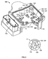
- Fig. 1 shows a first embodiment of a solenoid valve controller 100 according to the invention, which can be divided into substantially two portions.
- One portion comprises magnet coil yokes 130 which, together with magnet coils, actuate solenoid valve units 230 of a hydraulic device 200 (see Figs. 4 and 5 ).
- the other portion of the solenoid valve controller 100 comprises electrical elements 160, which are used to electrically control the magnet coils. These two portions are formed inside a control housing 110 of the solenoid valve controller 100 and are spatially separated from each other by an intermediate base or base 112.
- the magnet coils are supplied with electrical current or control signals from the electrical elements 160 via contacts or wires which are passed through passage recesses in the base 112.
- a plurality of the magnet coil yokes 130 are arranged in the control housing 110.
- the magnet coil yokes 130 are provided on elastomer elements 120, which resiliently fasten the magnet coil yokes 130 in the control housing 110.
- Each of the elastomer elements 120 is preferably located between two projections having recesses 114 in the base 112 in which the magnet coil yokes 130 are fixed in a radial direction with respect to their longitudinal axis.
- One of the recesses 114 is preferably reniform in this case whereas the other recess 114 is circular or cylindrical.
- the two recesses 114 are also preferably arranged so as to be diametrically opposed to each other with respect to the elastomer element.120.
- the magnet coil yoke 130 can be radially fixed in one or both of the recesses 114 by a pinching rib of the magnet coil yoke 130, for example.
- the two respective recesses 114 in addition to the radial fixing, provide adequate axial retention for the magnet coil yoke 130, so, on the one hand, the elastomer elements 120 remain on the recesses 114 and, on the other hand, the elastomer elements 120 cannot detach from the recesses 114 and become lost (for example in the event of a rotation (with respect to Fig. 1 ) of the solenoid valve controller 100).
- Radial fixing does not necessarily have to take place via the recesses 114 and the pinching rib.
- Other devices such as mutually corresponding projections and recesses (for example a cylinder portion which is displaceably guided in the longitudinal direction in a cylinder recess) on the magnet coil yoke 130 and on/in the base 112 are possible, which hold both parts in position so they are radially fixed with respect to each other.
- Security against the magnet coil yoke 130 falling out on rotation of the solenoid valve controller 100 can be provided, for example, by a conveying safeguard or corresponding latching hooks (for example on the cylinder portion) which only allow displacement of the magnet coil yoke 130 in a downward direction (with respect to Fig. 1 ).
- the elastomer element 120 is a segment of a sphere which is formed by a pole of a sphere with a parallel of latitude. It is also possible to form the elastomer element 120 from a segment of a sphere which is delimited by two parallels of latitude (or longitudinal parallels).
- the elastomer element 120 is preferably approximately a hemisphere 122 which is provided directly on the base 112 of the control housing 110.
- the elastomer element 122 can, however, also be provided on a support or base member 128 (see Fig. 2 ) which is secured in the base 112 of the control housing 110, as described below.
- twelve elastomer elements 120 are provided on the base 112 of the control housing 110 with a single magnet coil yoke 130 provided on each of the elastomer elements 120.
- Fig. 2 shows a second embodiment of elastomer elements 120 according to the invention which, on the one hand, have the form of a truncated cone 124 and, on the other hand, are rigidly connected to the control housing 110 by the support or base member 128.
- the base member 128 is rigidly connected to the base 112 of the control housing 110, for example, by gluing, riveting, latching, screwing or clipping.
- an extension of the base member 128 projects into an opening in the base 112, wherein the extension can engage, with projections formed thereon, in corresponding recesses in the opening or, for example, can latch by means of latching hooks on an opposing side of the base 112.
- the truncated cone 124 is fixed to the base member 128.
- the elastomer element 120 (for example the truncated cone elastomer element 124 or the hemispherical elastomer element 122) is cast directly onto the base 112 of the control housing 110 or the base member 128 by a casting process.
- Other ways of fastening the elastomer elements 120 to the base 112 or the base member 128 are possible, however, such as gluing or screwing/interlocking by means of a suitable device on the elastomer element 120. It is also possible to produce the base member 128 together with the elastomer element 120 in a two-component casting process.
- recesses 126 may be provided in the elastomer element 120. This can be seen for example in the detail A in Fig. 2 in the truncated cone 124.
- the truncated cone 124 is arranged with its wider diameter on the base member 128 and with the recess 126 extending centrally through the truncated cone 124 to its smaller diameter.
- the recess 126 is substantially cylindrical and the dimensions of which affect the resilient force, which is provided by the truncated cone 124.
- the recess 126 does not have to have a circular cylindrical form but can have any desired form as long as reliable pressing of the magnet coil yoke 130 onto the hydraulic device 200 is ensured.
- the recess 126 does not have to be centrally located in the elastomer element 120 or be arranged so as to pass through the elastomer element 120, but may be provided as desired inside the elastomer element 120.
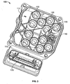
- Fig. 3 shows the solenoid valve controller 100 in its completely assembled state provided with twelve of the magnet coil yokes 130. In this state, the solenoid valve controller 100 can be screwed or rigidly connected to the hydraulic device 200 (see Figs. 4 and 5 ) for the hydraulic controller 300 for the ABS/ESP. An electrical connector 170 of the solenoid valve controller 100 or the hydraulic controller 300 can also clearly be seen in Fig. 3 , which connection provides the electrical elements 160 with electrical current and control commands.
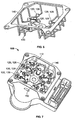
- Figs. 4 and 5 show details of the hydraulic controller 300 according to the invention in the assembled state with the solenoid valve controller 100 being securely screwed in a fluid-tight manner to the hydraulic device 200, and the elastomer element 120 of the magnet coil yoke 130 is positioned on the solenoid valve unit 230 in a predetermined defined position.
- the magnet coil yoke 130 at least partially surrounds the solenoid valve unit 230 in this case.
- the magnet coil yokes 130 protrude from the base 112 of the solenoid valve controller 100 slightly more upwardly (with respect to Figs. 1 , 3 , 4 and 5 ) than in the assembled state, so when connecting the solenoid valve controller 100 to the hydraulic device 200, the magnet coil yokes 130 are pressed by an outer side 220 of a housing 210 of the hydraulic device 200 onto the elastomer elements 120.
- the elastomer elements 120 impart to the magnet coil yokes 130 a defined pressing pressure to the outer side of the hydraulic device 200 and this ensures that the magnet coil yokes 130 are provided inside the hydraulic controller 300 so as to always adjoin, with their longitudinal ends, the outer side 220 of the hydraulic device 200 firmly and in a planar manner.
- Arrow F in Fig. 4 illustrates the direction of the force from the elastomer element 120 onto the magnet coil yoke 130.
- Fig. 4 also shows the two recesses 114, which serve as a centering and/or fixing device, in the base 112.
- the control housing 110 is preferably sealed from the outer side 220 of the hydraulic device 200 by a seal 140 provided along a housing edge of the control housing 110, as shown in Figs. 1 to 3 .
- a single seal 140 which completely surrounds the housing edge, is preferably used in this case.
- Fig. 6 shows an arrangement according to the invention of the seal 140 of the solenoid valve controller 100 on which the elastomer elements 120 are provided.
- the seal 140 may also be formed jointly with base members 128 via a web 150 instead of with the elastomer elements 120.
- the web 150 comprise the seal 140 and the elastomer elements 120 and can, for example, be produced by a casting process and subsequently be provided on the solenoid valve controller 100.
- the web 150 may also be provided directly on the solenoid valve controller 100 by an injection moulding process.
- Fig. 7 shows the solenoid valve controller 100 with the web 150 comprising the seal 140 and the elastomer elements 120 provided therein.
- the seal 140 thereby produces a fluid-tight connection between the solenoid valve controller 100 and the hydraulic device 200.
Landscapes
- Physics & Mathematics (AREA)
- Electromagnetism (AREA)
- Engineering & Computer Science (AREA)
- Fluid Mechanics (AREA)
- Transportation (AREA)
- Mechanical Engineering (AREA)
- Magnetically Actuated Valves (AREA)
- Regulating Braking Force (AREA)
Description
- The invention relates to a controller for solenoid valves, preferably a solenoid valve control unit for a hydraulic brake of a motor vehicle, and in particular the solenoid valve control unit of an antilock braking system (ABS) and/or an electronic stability program (ESP) of a motor vehicle. The invention also relates to an ABS/ESP hydraulic controller, wherein the solenoid valve controller according to the invention is rigidly connected to a hydraulic device.
- An ABS for a motor vehicle avoids excessive slipping between the tires and the road during braking, whereby the steering capacity and the lateral traction of the motor vehicle are maintained. An ABS four-channel system comprises two return pumps and two solenoid valves per wheel brake cylinder. Of the eight solenoid valves of the ABS for a car, four are usually open and the other four closed. When using the ABS during excessive slipping between the tires and the road, a line to the wheel brake cylinder of the wheel to be decelerated or the locking wheel is first blocked by a solenoid valve (that was previously open). If this is not sufficient to reduce the slipping or to release the locking wheel, the pressure is reduced by opening the other solenoid valve. At the same time, a return pump pumps brake fluid back into a line between the main brake cylinder and the solenoid valve. The excessive slipping is thereby reduced or the locking wheel can turn again, so a driver regains control of his vehicle.
- An ESP in a motor vehicle takes care of the stability of the vehicle by targeted deceleration of individual wheels, for example during cornering. The ESP obtains the information required for this via sensors at the rims, an accelerator pedal sensor, an angle sensor on the steering wheel, and longitudinal, transverse and rotary acceleration sensors. The ESP in particular prevents instability of the vehicle during cornering, which can occur for example in the event of unadjusted speed, an unpredictable change in the surface of the road (wetness, slickness, dirt accumulation) or in the event of a suddenly necessary swerve. An ESP computer unit detects the ESP case with the aid of the data supplied by the sensors and controls a targeted braking operation.
- The braking operations required for the ABS and the ESP are performed by a hydraulic controller which adjusts the requisite brake pressures at the caliper by means of solenoid valves. The hydraulic controller comprises a hydraulic device, also called a Hydraulic Control Unit (HCU), and a control device, also called an Electronic Control Unit (ECU). Valve units which open or close to control the brake fluid are located in the hydraulic device. The valve units are actuated by magnet coils which are located in the hydraulic controller.
- In hydraulic controllers in the prior art, each magnet coil or each magnet coil yoke of the hydraulic controller is cast with a thermoplastic elastomer to achieve a requisite resilient pressing force of the magnet coil yoke in a direction of the hydraulic device. These cast thermoplastic elastomers also seal the magnet coil yoke from the hydraulic device. The process of casting each individual magnet coil yoke is time-consuming, complex and entails high costs.
- Resilient elements made of a plastic material are also used in the prior art, which as separate, loose component parts, are used to provide a resilient force to the magnet coil yoke. Plastic resilient elements of this type can break and reduce the maximum operating temperature of the hydraulic controller as the plastic resilient elements soften at excessive temperatures and therefore diminish in resilient force. Assembly of the plastic resilient elements together with the magnet coil yoke is also time-consuming, and this in turn entails high production costs.
-
DE 198 33 498 A1 discloses a controller for a hydraulic brake which comprises an electronic control unit, flanged to a hydraulic unit, with coil units for solenoid valves. The coil units are fixed in the electronic control unit in this case between a base of the electronic control unit and a coil retention device located at free ends of the coils. Resilient mounting of the coil units takes place, on the one hand, via a resilient washer between the base of the electronic control unit and each coil unit and, on the other hand, via projections formed on the coil retention device and that are arranged mutually offset and so as to oppose one another, the projections providing, in collaboration with an outer side of the hydraulic unit, a second resilient force for the coil units. -
US 5,513,905 A discloses a valve control device of the kind used in ABS or ASR systems as applied in motor vehicles. Such a valve control device comprises a valve block that accommodates the solenoid valves and where a solenoid is assigned to each solenoid valve. The side of a solenoid holder facing the valve block has compartments for accommodating the solenoids, there being an elastic spring element on its compartment base that presses the solenoid against the valve block. -
WO 96/13415 -
WO 2005/058664 , representing closest prior art, discloses an electronic control unit for a motor vehicle braking systems. The control unit is used in motor vehicle braking systems which is connected to a hydraulic unit by means of a magnetic connector. The electronic control unit comprises several valve coils which are pushed by elastic elastomer rings against a metal plate which is a part of the valve block. -
US 5,520,447 A discloses a solenoid valve controller having an elastically deformable molded structure which biases the magnet coil yokes towards the hydraulic device and which comprises a sealing lip. - Assembly of the coil units with the resilient washers and that of the coil retention device is complex. As a respective resilient force is provided at the two opposing free ends of the coil units, exact positioning of the coil unit in the assembled state of the electronic control unit on the hydraulic unit is not always ensured either.
- It is an object of the invention to provide an improved controller for solenoid valves of a hydraulic device, which in particular allows simple assembly of the magnet coil yoke, on the one hand, is composed of a few component parts and, on other hand, ensures exact positioning of the magnet coil yoke on the hydraulic device at any time in the assembled state.
- The object of the invention is achieved by means of a controller for solenoid valve units of a hydraulic device, wherein a respective magnet coil yoke of the controller is pressed against an outer side of the hydraulic device by an elastomer element that provides a resilient force. According to the invention, the respective magnet coil yoke in this case preferably sits on the elastomer element, which is arranged on a base or an intermediate base of the controller. Furthermore, the elastomer element and a seal of the solenoid valve controller form a connected web.
- According to the invention, play-free mounting of the magnet coil yoke in a hydraulic controller can be simply achieved. By means of the arrangement of the intermediate base, the elastomer element, the magnet coil yoke and the outer side of the hydraulic device in series, pressing of the magnet coil yoke after combining the controller with the hydraulic device is possible, on the one hand, and exact positioning of the magnet coil yoke in the controller, and thus also above the solenoid valve element of the hydraulic device, is achieved, on the other hand. This applies in particular to exact axial positioning of the magnet coil yoke. The elastomer elements and the outer side of the hydraulic device each serve as bearings for the magnet coil yoke.
- Overall the thermal stability of the solenoid valve controller is increased by the use of elastomer elements which have a higher thermal stability than the plastic material of the resilient elements used previously. In the prior art, a solenoid valve controller could have a maximum temperature of 120 °C without excessive losses in resilient force being indicated on the resilient elements. According to the invention, this weak point is eliminated, so the use of the elastomer elements increases the thermal stability of the solenoid valve controller and thus also that of the hydraulic controller to up to 180 °C.
- Owing to the simple construction of the solenoid valve controller, it is possible to use a simply constructed tool during assembly thereof. Separate, loose resilient elements are also no longer required, as the elastomer elements can be provided so as to be directly and rigidly connected to the intermediate base of the solenoid valve controller.
- The invention makes it possible to provide a defined pressing force of the magnet coil yoke onto the hydraulic device virtually exclusively via the elastomer element, in other words the material thereof and its shaping. The arrangement of the elastomer elements also allows simple adaptation of the material or geometry to changing conditions in the production process as according to the invention it is easy to adjust the pressing force of the magnet coil yoke onto the hydraulic device. Thus, for example, when casting the elastomer elements onto the intermediate base, only slightly more or less elastomer per magnet coil yoke needs to be applied and thus a slightly more rigid or slightly weaker mounting can be achieved.
- According to the invention, complete casting of the magnet coil yoke is no longer necessary, so a lot of casting material and time can be saved. Furthermore, compared with the prior art, a more simply constructed solenoid valve controller is provided.
- In a preferred embodiment of the invention, the elastomer elements have the form of a segment or section of a sphere or that of a truncated cone. The form of a completely filled hemisphere or a droplet form of the elastomer material, which is freely established after casting and depends on a surface tension of the casting material in the liquid state or the thixotropy thereof, is particularly preferred. So the elastomer elements have a specific resilience when pressed together, they may be provided with recesses, a hole-like recess preferably being centrally provided through the elastomer element.
- During production of the solenoid valve controller, the elastomer element may be provided directly on the intermediate base of the control housing or on a base member which is then secured in the intermediate base. This can take place for example by gluing or a different type of mechanical fastening. Direct casting of the elastomer element onto the base or base member is preferred.
- In a preferred embodiment of the invention, the elastomer element and a seal, via which the solenoid valve controller can be fixed in a fluid-tight manner on the hydraulic device, consist of the same material, whereby it is possible to provide the elastomer elements and the seal on the control housing in one operation, a two-component casting process preferably being used for this purpose. It is also possible to provide the seal of the solenoid valve controller on the base members of the elastomer elements, wherein for example the elastomer elements and the seal may be provided on the base members using a casting process. However, it is also possible to produce the elastomer elements and the seal of the solenoid controller from two different materials.
- A preferred material for the elastomer element, as well as for the seal, is a silicone compound, so the entire solenoid valve controller is more heat resistant.
- According to the invention, a simply constructed solenoid valve controller is provided, during the production of which the previous complex and separate casting process of the magnet coil yoke is replaced by the provision of elastomer elements on the intermediate base and the preferably completely peripheral seal on a housing edge of the solenoid valve controller. The elastomer element is also not so detrimental to the position of the magnet coil yoke, as in the prior art, in which the resilient elements used tend to distort or warp.
- Further preferred embodiments of the invention can be found in the remaining dependent claims.
- The invention will be described in more detail herein with reference to the drawings, in which:
-
Fig. 1 shows a first embodiment of a solenoid valve controller according to the invention in a partially sectional 3D view; -
Fig. 2 shows a second embodiment of the solenoid valve controller according to the invention in a partially sectional 3D view and a detailed view A of an elastomer element according to the invention; -
Fig. 3 shows a completely assembled solenoid valve controller according to the invention; -
Fig. 4 shows a first sectional side view of an arrangement according to the invention of the elastomer element and a magnet coil yoke; -
Fig. 5 shows a second sectional side view of the arrangement according to the invention of the elastomer element and the magnet coil yoke; -
Fig. 6 shows a web having plurality of the elastomer elements according to the invention or support members in connection with a seal of the solenoid valve controller; and -
Fig. 7 shows the arrangement ofFig. 6 assembled in the solenoid valve controller. - The following statements relate to a solenoid valve controller of an ABS or an ESP of a motor vehicle, wherein the intention is not to restrict the invention hereto however, rather it should include general controllers for solenoid valves. The statements also relate to the portion of an ABS/ESP controller in which magnet coil yokes are housed. However, the intention is not to restrict the invention to this portion of the controller, rather, on the one hand, it should include a solenoid valve controller which comprises the magnet coil yoke in one portion and the corresponding electrical elements in another, and, on the other hand, is intended to relate to a hydraulic controller which comprises the solenoid valve controller according to the invention assembled on a hydraulic device.
-
Fig. 1 shows a first embodiment of asolenoid valve controller 100 according to the invention, which can be divided into substantially two portions. One portion comprises magnet coil yokes 130 which, together with magnet coils, actuatesolenoid valve units 230 of a hydraulic device 200 (seeFigs. 4 and 5 ). The other portion of thesolenoid valve controller 100 compriseselectrical elements 160, which are used to electrically control the magnet coils. These two portions are formed inside acontrol housing 110 of thesolenoid valve controller 100 and are spatially separated from each other by an intermediate base orbase 112. The magnet coils are supplied with electrical current or control signals from theelectrical elements 160 via contacts or wires which are passed through passage recesses in thebase 112. - In the illustrated embodiment, a plurality of the magnet coil yokes 130 are arranged in the
control housing 110. The magnet coil yokes 130 are provided onelastomer elements 120, which resiliently fasten the magnet coil yokes 130 in thecontrol housing 110. Each of theelastomer elements 120 is preferably located between twoprojections having recesses 114 in the base 112 in which the magnet coil yokes 130 are fixed in a radial direction with respect to their longitudinal axis. One of therecesses 114 is preferably reniform in this case whereas theother recess 114 is circular or cylindrical. The tworecesses 114 are also preferably arranged so as to be diametrically opposed to each other with respect to the elastomer element.120. themagnet coil yoke 130 can be radially fixed in one or both of therecesses 114 by a pinching rib of themagnet coil yoke 130, for example. The tworespective recesses 114, in addition to the radial fixing, provide adequate axial retention for themagnet coil yoke 130, so, on the one hand, theelastomer elements 120 remain on therecesses 114 and, on the other hand, theelastomer elements 120 cannot detach from therecesses 114 and become lost (for example in the event of a rotation (with respect toFig. 1 ) of the solenoid valve controller 100). - Radial fixing does not necessarily have to take place via the
recesses 114 and the pinching rib. Other devices, such as mutually corresponding projections and recesses (for example a cylinder portion which is displaceably guided in the longitudinal direction in a cylinder recess) on themagnet coil yoke 130 and on/in thebase 112 are possible, which hold both parts in position so they are radially fixed with respect to each other. Security against themagnet coil yoke 130 falling out on rotation of thesolenoid valve controller 100 can be provided, for example, by a conveying safeguard or corresponding latching hooks (for example on the cylinder portion) which only allow displacement of themagnet coil yoke 130 in a downward direction (with respect toFig. 1 ). - In the illustrated embodiment of
Fig. 1 , theelastomer element 120 is a segment of a sphere which is formed by a pole of a sphere with a parallel of latitude. It is also possible to form theelastomer element 120 from a segment of a sphere which is delimited by two parallels of latitude (or longitudinal parallels). Theelastomer element 120 is preferably approximately a hemisphere 122 which is provided directly on thebase 112 of thecontrol housing 110. The elastomer element 122 can, however, also be provided on a support or base member 128 (seeFig. 2 ) which is secured in thebase 112 of thecontrol housing 110, as described below. - In a preferred embodiment of the invention, twelve
elastomer elements 120 are provided on thebase 112 of thecontrol housing 110 with a singlemagnet coil yoke 130 provided on each of theelastomer elements 120. -
Fig. 2 shows a second embodiment ofelastomer elements 120 according to the invention which, on the one hand, have the form of a truncated cone 124 and, on the other hand, are rigidly connected to thecontrol housing 110 by the support orbase member 128. This can be seen more clearly in a detail A inFig. 2 in which thebase member 128 is rigidly connected to thebase 112 of thecontrol housing 110, for example, by gluing, riveting, latching, screwing or clipping. In the illustrated example, an extension of thebase member 128 projects into an opening in thebase 112, wherein the extension can engage, with projections formed thereon, in corresponding recesses in the opening or, for example, can latch by means of latching hooks on an opposing side of thebase 112. The truncated cone 124 is fixed to thebase member 128. - In a preferred embodiment of the invention, the elastomer element 120 (for example the truncated cone elastomer element 124 or the hemispherical elastomer element 122) is cast directly onto the
base 112 of thecontrol housing 110 or thebase member 128 by a casting process. Other ways of fastening theelastomer elements 120 to the base 112 or thebase member 128 are possible, however, such as gluing or screwing/interlocking by means of a suitable device on theelastomer element 120. It is also possible to produce thebase member 128 together with theelastomer element 120 in a two-component casting process. - In a preferred embodiment of the invention, recesses 126 may be provided in the
elastomer element 120. This can be seen for example in the detail A inFig. 2 in the truncated cone 124. In this embodiment, the truncated cone 124 is arranged with its wider diameter on thebase member 128 and with therecess 126 extending centrally through the truncated cone 124 to its smaller diameter. Therecess 126 is substantially cylindrical and the dimensions of which affect the resilient force, which is provided by the truncated cone 124. - Other resilient forces may be produced depending on the size of the
recess 126 in theelastomer element 120. Therecess 126 does not have to have a circular cylindrical form but can have any desired form as long as reliable pressing of themagnet coil yoke 130 onto thehydraulic device 200 is ensured. Therecess 126 does not have to be centrally located in theelastomer element 120 or be arranged so as to pass through theelastomer element 120, but may be provided as desired inside theelastomer element 120. -
Fig. 3 shows thesolenoid valve controller 100 in its completely assembled state provided with twelve of the magnet coil yokes 130. In this state, thesolenoid valve controller 100 can be screwed or rigidly connected to the hydraulic device 200 (seeFigs. 4 and 5 ) for thehydraulic controller 300 for the ABS/ESP. Anelectrical connector 170 of thesolenoid valve controller 100 or thehydraulic controller 300 can also clearly be seen inFig. 3 , which connection provides theelectrical elements 160 with electrical current and control commands. -
Figs. 4 and 5 show details of thehydraulic controller 300 according to the invention in the assembled state with thesolenoid valve controller 100 being securely screwed in a fluid-tight manner to thehydraulic device 200, and theelastomer element 120 of themagnet coil yoke 130 is positioned on thesolenoid valve unit 230 in a predetermined defined position. Themagnet coil yoke 130 at least partially surrounds thesolenoid valve unit 230 in this case. - Before the
hydraulic controller 300 is assembled, the magnet coil yokes 130 protrude from thebase 112 of thesolenoid valve controller 100 slightly more upwardly (with respect toFigs. 1 ,3 ,4 and 5 ) than in the assembled state, so when connecting thesolenoid valve controller 100 to thehydraulic device 200, the magnet coil yokes 130 are pressed by anouter side 220 of ahousing 210 of thehydraulic device 200 onto theelastomer elements 120. As a result, theelastomer elements 120 impart to the magnet coil yokes 130 a defined pressing pressure to the outer side of thehydraulic device 200 and this ensures that the magnet coil yokes 130 are provided inside thehydraulic controller 300 so as to always adjoin, with their longitudinal ends, theouter side 220 of thehydraulic device 200 firmly and in a planar manner. - As a result, play-free positioning of the
magnet coil yoke 130 on or above thesolenoid valve units 230 is ensured with tolerance compensation between the ECU-sidemagnet coil yoke 130 and the HCU-sidesolenoid valve units 230 being achieved. The amount of the pressure and the requisite tolerance compensation may be freely adjusted over a wide range via the material of theelastomer elements 120 and the geometry of theelastomer elements 120. - Arrow F in
Fig. 4 illustrates the direction of the force from theelastomer element 120 onto themagnet coil yoke 130.Fig. 4 also shows the tworecesses 114, which serve as a centering and/or fixing device, in thebase 112. - The
control housing 110 is preferably sealed from theouter side 220 of thehydraulic device 200 by aseal 140 provided along a housing edge of thecontrol housing 110, as shown inFigs. 1 to 3 . Asingle seal 140, which completely surrounds the housing edge, is preferably used in this case. -
Fig. 6 shows an arrangement according to the invention of theseal 140 of thesolenoid valve controller 100 on which theelastomer elements 120 are provided. Theseal 140 may also be formed jointly withbase members 128 via aweb 150 instead of with theelastomer elements 120. - The
web 150 comprise theseal 140 and theelastomer elements 120 and can, for example, be produced by a casting process and subsequently be provided on thesolenoid valve controller 100. Theweb 150 may also be provided directly on thesolenoid valve controller 100 by an injection moulding process. According to a preferred embodiment of the invention, it is also possible to produce theweb 150 in a two-component process with the elastomer elements 120 (or the base members 128) and theseal 140 consisting of two different materials. This simple construction of theweb 150 means theseal 140 and the elastomer elements 120 (or the base members 128) may be produced simultaneously in one operation. -
Fig. 7 shows thesolenoid valve controller 100 with theweb 150 comprising theseal 140 and theelastomer elements 120 provided therein. Theseal 140 thereby produces a fluid-tight connection between thesolenoid valve controller 100 and thehydraulic device 200.
Claims (13)
- Solenoid valve controller (100) for an antilock braking system or an electronic stability program of a motor vehicle, which can be rigidly connected to an outer side of a hydraulic device (200) via a seal (140), wherein
an elastomer element (120) is arranged on a base (112) of a control housing (110) of the solenoid valve controller (100) so as to protrude inwardly into the control housing (110), and a magnet coil yoke (130) can be provided on the elastomer element (120), wherein the magnet coil yoke (130) can be pushed directly onto the outer side of the hydraulic device (200) by means of the elastomer element (120) together with the control housing (110), and in so doing can receive a solenoid valve unit (230) of the hydraulic device (200) on the inside, wherein,
on the one hand, the elastomer element (120) serves as a bearing and, on the other hand, the outer side of the hydraulic device (200) can serve as an abutment for the magnet coil yoke (130), and as a result the magnet coil yoke (130) can be fixed without play in the control housing (110),
characterised in that the elastomer element (120) and the seal (140) of the solenoid valve controller (100) form a connected web (150). - Solenoid valve controller according to claim 1, characterised in that interference fit of the magnet coil yoke (130) in the connector housing (110) is influenced exclusively by the material and/or the geometry of the elastomer element (120) and thus the pressing force thereof onto the hydraulic device (200) is determined.
- Solenoid valve controller according to either claim 1 or claim 2, characterised in that the elastomer element (120) has the form of an at least partially spherical body and preferably has the form of a segment or a section of a sphere or ellipsoid, in particular the form of a hemisphere (122), or the elastomer element (120) has the form of a truncated cone (124), of a cylinder, a torus or a barrel.
- Solenoid valve controller according to any one of claims 1 to 3, characterised in that the elastomer element (120) is manufactured from solid material and does not have a recess (126), or has a recess (126) which is preferably centrally provided in the elastomer element (120) and in particular passes completely through the elastomer element (120).
- Solenoid valve controller according to any one of claims 1 to 4, characterised in that the elastomer element (120) is secured to a base member (128) which is in turn fastened in the base (112) of the control housing (110).
- Solenoid valve controller according to any one of claims 1 to 5, characterised in that the elastomer element (120) is manufactured from a material of which the seal (140) for the solenoid valve controller (100) also consists, or the elastomer element (120) and the seal (140) of the solenoid valve controller (100) are produced from two different materials.
- Solenoid valve controller according to claim 5 or 6, when dependent on claim 5, characterised in that the elastomer element (120) is provided on the base member (128) of the control housing (110) by means of a casting process.
- Solenoid valve controller according to any one of claims 1 to 4 or 6, when not dependent on claim 5, characterised in that the elastomer element (120) is provided on the base (112) of the control housing (110) by means of a casting process.
- Solenoid valve controller according to any one of claims 1 to 8, characterised in that the connected web (150) is produced by a two-component casting process.
- Solenoid valve controller according to claim 5 or 7, characterised in that the seal (140) is connected to the base member (128) of the elastomer element (120).
- Solenoid valve controller according to any one of claims 1 to 10, characterised in that the elastomer element (120) and preferably also the seal (140) comprise silicone and the control housing (110) is in particular an ABS plastic material housing.
- Solenoid valve controller according to any one of claims 1 to 11, characterised in that the base (112) of the control housing (110) is substantially flat.
- Hydraulic controller for an antilock braking system or an electronic stability program of a motor vehicle, comprising a solenoid valve controller (100) according to any one of claims 1 to 12 and a hydraulic device (200),
characterised in that the solenoid valve controller (100) is rigidly connected to the hydraulic device (200), wherein a magnet coil yoke (130) partially receives a solenoid valve unit (230) of the hydraulic device (200).
Priority Applications (1)
| Application Number | Priority Date | Filing Date | Title |
|---|---|---|---|
| PL06791739T PL1919748T3 (en) | 2005-08-31 | 2006-08-30 | Solenoid valve controller |
Applications Claiming Priority (2)
| Application Number | Priority Date | Filing Date | Title |
|---|---|---|---|
| DE102005041240A DE102005041240B4 (en) | 2005-08-31 | 2005-08-31 | Solenoid valve control device and hydraulic control device |
| PCT/EP2006/008490 WO2007025741A1 (en) | 2005-08-31 | 2006-08-30 | Solenoid valve controller |
Publications (2)
| Publication Number | Publication Date |
|---|---|
| EP1919748A1 EP1919748A1 (en) | 2008-05-14 |
| EP1919748B1 true EP1919748B1 (en) | 2012-11-28 |
Family
ID=37265126
Family Applications (1)
| Application Number | Title | Priority Date | Filing Date |
|---|---|---|---|
| EP06791739A Active EP1919748B1 (en) | 2005-08-31 | 2006-08-30 | Solenoid valve controller |
Country Status (7)
| Country | Link |
|---|---|
| US (1) | US8091968B2 (en) |
| EP (1) | EP1919748B1 (en) |
| CN (1) | CN101253085B (en) |
| DE (1) | DE102005041240B4 (en) |
| ES (1) | ES2406631T3 (en) |
| PL (1) | PL1919748T3 (en) |
| WO (1) | WO2007025741A1 (en) |
Families Citing this family (9)
| Publication number | Priority date | Publication date | Assignee | Title |
|---|---|---|---|---|
| DE102007019800B4 (en) | 2007-04-26 | 2012-03-01 | Tyco Electronics Belgium Ec Bvba | Magnetic coil assembly and method of manufacture |
| DE102009030887B4 (en) * | 2009-06-29 | 2022-01-05 | Robert Bosch Gmbh | Valve arrangement |
| DE102010008033A1 (en) * | 2010-02-13 | 2011-08-18 | Ipgate Ag | Brake system with pressure model and prioritization device |
| EP2540588A1 (en) * | 2011-07-01 | 2013-01-02 | Tyco Electronics Belgium EC BVBA | Module for a braking system, such as a coil box module comprising a housing and a connector |
| WO2013147254A1 (en) | 2012-03-30 | 2013-10-03 | 日信工業株式会社 | Brake hydraulic device for vehicle |
| JP2018083572A (en) * | 2016-11-25 | 2018-05-31 | ローベルト ボッシュ ゲゼルシャフト ミット ベシュレンクテル ハフツング | Brake fluid pressure control device and motorcycle brake system |
| JP2020047768A (en) * | 2018-09-19 | 2020-03-26 | 日立オートモティブシステムズ株式会社 | Electronic control device |
| KR20250056368A (en) * | 2023-10-19 | 2025-04-28 | 엘에스오토모티브테크놀로지스 주식회사 | Housing structure for fixing solenoid coil assembly and housing assembly for controlling anti-lock brake system having the same |
| KR20260006324A (en) * | 2024-07-04 | 2026-01-13 | 엘에스오토모티브테크놀로지스 주식회사 | Break housing assembly and control system thereof |
Family Cites Families (15)
| Publication number | Priority date | Publication date | Assignee | Title |
|---|---|---|---|---|
| GB2249874B (en) * | 1990-11-17 | 1994-09-21 | Motorola Gmbh | Elastomeric seating member |
| JP3329455B2 (en) * | 1991-01-15 | 2002-09-30 | アルフレッド・テヴェス・ゲーエムベーハー | Electro-hydraulic pressure control device |
| DE4133641B4 (en) * | 1991-10-11 | 2005-02-17 | Continental Teves Ag & Co. Ohg | Electrohydraulic pressure control device |
| DE4343325A1 (en) * | 1993-12-18 | 1995-06-22 | Telefunken Microelectron | Valve control device |
| JPH0854081A (en) * | 1994-08-09 | 1996-02-27 | Nisshinbo Ind Inc | Pressure control device |
| DE4436618A1 (en) * | 1994-10-13 | 1996-04-18 | Bosch Gmbh Robert | Electro-hydraulic pressure adjustment device, in particular for a slip-controlled vehicle brake system |
| WO1996013415A1 (en) | 1994-10-28 | 1996-05-09 | Siemens Aktiengesellschaft | Valve control device |
| DE19518519C2 (en) * | 1995-05-19 | 1998-07-16 | Siemens Ag | Valve control unit |
| DE29508389U1 (en) * | 1995-05-19 | 1995-07-20 | Siemens AG, 80333 München | Solenoid coil for valve control |
| FR2766546B1 (en) * | 1997-07-22 | 1999-10-22 | Peugeot | ELECTROVALVE ARRANGEMENT WITH ELASTIC FIXING ON ITS SUPPORT, SUCH AS A HYDRAULIC BLOCK |
| JPH1143031A (en) * | 1997-07-25 | 1999-02-16 | Nisshinbo Ind Inc | Hydraulic brake control device |
| DE19940696A1 (en) * | 1999-04-15 | 2000-10-19 | Continental Teves Ag & Co Ohg | Coil mounting for magnetically operated valves of motor vehicle brake control system |
| DE10003055B4 (en) * | 2000-01-25 | 2004-09-09 | Fci Automotive Deutschland Gmbh | Control unit of a valve mechanism |
| US20080017174A1 (en) * | 2003-12-17 | 2008-01-24 | Continental Teves Ag & Co. Ohg | Electronic Control Unit for Motor Vehicle Braking Systems |
| US7237850B2 (en) * | 2004-09-21 | 2007-07-03 | Advics Co., Ltd. | Fluid control apparatus |
-
2005
- 2005-08-31 DE DE102005041240A patent/DE102005041240B4/en not_active Expired - Fee Related
-
2006
- 2006-08-30 CN CN200680031478.4A patent/CN101253085B/en active Active
- 2006-08-30 PL PL06791739T patent/PL1919748T3/en unknown
- 2006-08-30 US US12/063,077 patent/US8091968B2/en active Active
- 2006-08-30 ES ES06791739T patent/ES2406631T3/en active Active
- 2006-08-30 EP EP06791739A patent/EP1919748B1/en active Active
- 2006-08-30 WO PCT/EP2006/008490 patent/WO2007025741A1/en not_active Ceased
Also Published As
| Publication number | Publication date |
|---|---|
| WO2007025741A1 (en) | 2007-03-08 |
| CN101253085B (en) | 2014-01-29 |
| DE102005041240A1 (en) | 2007-03-08 |
| DE102005041240B4 (en) | 2009-04-30 |
| CN101253085A (en) | 2008-08-27 |
| ES2406631T3 (en) | 2013-06-07 |
| US20100219680A1 (en) | 2010-09-02 |
| US8091968B2 (en) | 2012-01-10 |
| EP1919748A1 (en) | 2008-05-14 |
| PL1919748T3 (en) | 2013-04-30 |
Similar Documents
| Publication | Publication Date | Title |
|---|---|---|
| JP7529122B2 (en) | Pedal device and method for manufacturing the pedal device | |
| RU2517630C2 (en) | Restrictor valve for vehicle abs working fluid pressure control and method of its fabrication | |
| US20180170334A1 (en) | Hydraulic Power Unit of a Brake Control System of a Vehicle Hydraulic Brake System | |
| US9758134B2 (en) | Disk brake | |
| RU2507093C2 (en) | Restrictor valve with membrane valves for working fluid pressure control in vehicle antiskid system brake with valve seat permanently integrated with valve body from polymer material | |
| US9410638B2 (en) | Solenoid valve with shaped spring | |
| CN100398368C (en) | Method and device for controlling a motor vehicle with an electrohydraulic braking system | |
| US20120326495A1 (en) | Abs hydraulic unit with accumulator | |
| US8091968B2 (en) | Solenoid valve controller | |
| US20160121864A1 (en) | Brake apparatus and brake system | |
| KR20140030227A (en) | Pedal travel simulator, actuating unit for a hydraulic brake system and brake system | |
| CN117412889A (en) | Pedal device | |
| CN113557183B (en) | Hydraulic unit | |
| KR20170010915A (en) | Master cylinder for a regulated braking system | |
| US20240059260A1 (en) | Brake pedal device | |
| US20220228635A1 (en) | Drum brake having a load measurement device | |
| KR20180132759A (en) | Automotive braking force simulator | |
| CN109843665B (en) | Solenoid valves and hydraulic braking systems for vehicles | |
| US20190049025A1 (en) | Check valve | |
| US5437217A (en) | Pneumatic booster | |
| CN101284526B (en) | Valve for anti-lock brake system | |
| US20050057092A1 (en) | Hydraulic pressure controller | |
| KR20060126646A (en) | Method and apparatus for control of automobile equipped with electrohydraulic brake system with driving dynamics control | |
| KR200281991Y1 (en) | Solenoid of anti-lock brake system | |
| US20090000467A1 (en) | Hydraulic Unit |
Legal Events
| Date | Code | Title | Description |
|---|---|---|---|
| PUAI | Public reference made under article 153(3) epc to a published international application that has entered the european phase |
Free format text: ORIGINAL CODE: 0009012 |
|
| 17P | Request for examination filed |
Effective date: 20080131 |
|
| AK | Designated contracting states |
Kind code of ref document: A1 Designated state(s): AT BE BG CH CY CZ DE DK EE ES FI FR GB GR HU IE IS IT LI LT LU LV MC NL PL PT RO SE SI SK TR |
|
| RIN1 | Information on inventor provided before grant (corrected) |
Inventor name: DEWART, WOLFGANG Inventor name: SIOTTO, MICHAEL Inventor name: VAN CAUWENBERGE, JAN Inventor name: COLPAERT, BART Inventor name: DESLOOVERE, PETER |
|
| RIN1 | Information on inventor provided before grant (corrected) |
Inventor name: SIOTTO, MICHAEL Inventor name: DEWART, WOLFGANG Inventor name: DESLOOVERE, PETER Inventor name: COLPAERT, BART Inventor name: VAN CAUWENBERGE, JAN |
|
| 17Q | First examination report despatched |
Effective date: 20090327 |
|
| RAP1 | Party data changed (applicant data changed or rights of an application transferred) |
Owner name: LUCAS AUTOMOTIVE GMBH Owner name: TYCO ELECTRONICS BELGIUM EC BVBA |
|
| GRAP | Despatch of communication of intention to grant a patent |
Free format text: ORIGINAL CODE: EPIDOSNIGR1 |
|
| DAX | Request for extension of the european patent (deleted) | ||
| GRAS | Grant fee paid |
Free format text: ORIGINAL CODE: EPIDOSNIGR3 |
|
| GRAA | (expected) grant |
Free format text: ORIGINAL CODE: 0009210 |
|
| AK | Designated contracting states |
Kind code of ref document: B1 Designated state(s): AT BE BG CH CY CZ DE DK EE ES FI FR GB GR HU IE IS IT LI LT LU LV MC NL PL PT RO SE SI SK TR |
|
| REG | Reference to a national code |
Ref country code: GB Ref legal event code: FG4D |
|
| REG | Reference to a national code |
Ref country code: CH Ref legal event code: EP |
|
| REG | Reference to a national code |
Ref country code: AT Ref legal event code: REF Ref document number: 585983 Country of ref document: AT Kind code of ref document: T Effective date: 20121215 |
|
| REG | Reference to a national code |
Ref country code: IE Ref legal event code: FG4D |
|
| REG | Reference to a national code |
Ref country code: DE Ref legal event code: R096 Ref document number: 602006033367 Country of ref document: DE Effective date: 20130124 |
|
| REG | Reference to a national code |
Ref country code: SE Ref legal event code: TRGR |
|
| REG | Reference to a national code |
Ref country code: NL Ref legal event code: VDEP Effective date: 20121128 |
|
| REG | Reference to a national code |
Ref country code: LT Ref legal event code: MG4D |
|
| PG25 | Lapsed in a contracting state [announced via postgrant information from national office to epo] |
Ref country code: LT Free format text: LAPSE BECAUSE OF FAILURE TO SUBMIT A TRANSLATION OF THE DESCRIPTION OR TO PAY THE FEE WITHIN THE PRESCRIBED TIME-LIMIT Effective date: 20121128 Ref country code: FI Free format text: LAPSE BECAUSE OF FAILURE TO SUBMIT A TRANSLATION OF THE DESCRIPTION OR TO PAY THE FEE WITHIN THE PRESCRIBED TIME-LIMIT Effective date: 20121128 |
|
| REG | Reference to a national code |
Ref country code: PL Ref legal event code: T3 |
|
| PG25 | Lapsed in a contracting state [announced via postgrant information from national office to epo] |
Ref country code: PT Free format text: LAPSE BECAUSE OF FAILURE TO SUBMIT A TRANSLATION OF THE DESCRIPTION OR TO PAY THE FEE WITHIN THE PRESCRIBED TIME-LIMIT Effective date: 20130328 Ref country code: SI Free format text: LAPSE BECAUSE OF FAILURE TO SUBMIT A TRANSLATION OF THE DESCRIPTION OR TO PAY THE FEE WITHIN THE PRESCRIBED TIME-LIMIT Effective date: 20121128 Ref country code: LV Free format text: LAPSE BECAUSE OF FAILURE TO SUBMIT A TRANSLATION OF THE DESCRIPTION OR TO PAY THE FEE WITHIN THE PRESCRIBED TIME-LIMIT Effective date: 20121128 Ref country code: GR Free format text: LAPSE BECAUSE OF FAILURE TO SUBMIT A TRANSLATION OF THE DESCRIPTION OR TO PAY THE FEE WITHIN THE PRESCRIBED TIME-LIMIT Effective date: 20130301 Ref country code: BE Free format text: LAPSE BECAUSE OF FAILURE TO SUBMIT A TRANSLATION OF THE DESCRIPTION OR TO PAY THE FEE WITHIN THE PRESCRIBED TIME-LIMIT Effective date: 20121128 |
|
| REG | Reference to a national code |
Ref country code: ES Ref legal event code: FG2A Ref document number: 2406631 Country of ref document: ES Kind code of ref document: T3 Effective date: 20130607 |
|
| PG25 | Lapsed in a contracting state [announced via postgrant information from national office to epo] |
Ref country code: DK Free format text: LAPSE BECAUSE OF FAILURE TO SUBMIT A TRANSLATION OF THE DESCRIPTION OR TO PAY THE FEE WITHIN THE PRESCRIBED TIME-LIMIT Effective date: 20121128 Ref country code: CY Free format text: LAPSE BECAUSE OF FAILURE TO SUBMIT A TRANSLATION OF THE DESCRIPTION OR TO PAY THE FEE WITHIN THE PRESCRIBED TIME-LIMIT Effective date: 20121128 Ref country code: SK Free format text: LAPSE BECAUSE OF FAILURE TO SUBMIT A TRANSLATION OF THE DESCRIPTION OR TO PAY THE FEE WITHIN THE PRESCRIBED TIME-LIMIT Effective date: 20121128 Ref country code: EE Free format text: LAPSE BECAUSE OF FAILURE TO SUBMIT A TRANSLATION OF THE DESCRIPTION OR TO PAY THE FEE WITHIN THE PRESCRIBED TIME-LIMIT Effective date: 20121128 Ref country code: BG Free format text: LAPSE BECAUSE OF FAILURE TO SUBMIT A TRANSLATION OF THE DESCRIPTION OR TO PAY THE FEE WITHIN THE PRESCRIBED TIME-LIMIT Effective date: 20130228 |
|
| PG25 | Lapsed in a contracting state [announced via postgrant information from national office to epo] |
Ref country code: NL Free format text: LAPSE BECAUSE OF FAILURE TO SUBMIT A TRANSLATION OF THE DESCRIPTION OR TO PAY THE FEE WITHIN THE PRESCRIBED TIME-LIMIT Effective date: 20121128 Ref country code: RO Free format text: LAPSE BECAUSE OF FAILURE TO SUBMIT A TRANSLATION OF THE DESCRIPTION OR TO PAY THE FEE WITHIN THE PRESCRIBED TIME-LIMIT Effective date: 20121128 |
|
| PLBE | No opposition filed within time limit |
Free format text: ORIGINAL CODE: 0009261 |
|
| STAA | Information on the status of an ep patent application or granted ep patent |
Free format text: STATUS: NO OPPOSITION FILED WITHIN TIME LIMIT |
|
| REG | Reference to a national code |
Ref country code: HU Ref legal event code: AG4A Ref document number: E016969 Country of ref document: HU |
|
| 26N | No opposition filed |
Effective date: 20130829 |
|
| REG | Reference to a national code |
Ref country code: DE Ref legal event code: R097 Ref document number: 602006033367 Country of ref document: DE Effective date: 20130829 |
|
| REG | Reference to a national code |
Ref country code: CH Ref legal event code: PL |
|
| PG25 | Lapsed in a contracting state [announced via postgrant information from national office to epo] |
Ref country code: CH Free format text: LAPSE BECAUSE OF NON-PAYMENT OF DUE FEES Effective date: 20130831 Ref country code: MC Free format text: LAPSE BECAUSE OF FAILURE TO SUBMIT A TRANSLATION OF THE DESCRIPTION OR TO PAY THE FEE WITHIN THE PRESCRIBED TIME-LIMIT Effective date: 20121128 Ref country code: LI Free format text: LAPSE BECAUSE OF NON-PAYMENT OF DUE FEES Effective date: 20130831 |
|
| REG | Reference to a national code |
Ref country code: IE Ref legal event code: MM4A |
|
| PG25 | Lapsed in a contracting state [announced via postgrant information from national office to epo] |
Ref country code: IE Free format text: LAPSE BECAUSE OF NON-PAYMENT OF DUE FEES Effective date: 20130830 |
|
| PG25 | Lapsed in a contracting state [announced via postgrant information from national office to epo] |
Ref country code: TR Free format text: LAPSE BECAUSE OF FAILURE TO SUBMIT A TRANSLATION OF THE DESCRIPTION OR TO PAY THE FEE WITHIN THE PRESCRIBED TIME-LIMIT Effective date: 20121128 |
|
| PG25 | Lapsed in a contracting state [announced via postgrant information from national office to epo] |
Ref country code: LU Free format text: LAPSE BECAUSE OF NON-PAYMENT OF DUE FEES Effective date: 20130830 |
|
| PG25 | Lapsed in a contracting state [announced via postgrant information from national office to epo] |
Ref country code: IS Free format text: LAPSE BECAUSE OF FAILURE TO SUBMIT A TRANSLATION OF THE DESCRIPTION OR TO PAY THE FEE WITHIN THE PRESCRIBED TIME-LIMIT Effective date: 20121128 |
|
| REG | Reference to a national code |
Ref country code: FR Ref legal event code: PLFP Year of fee payment: 11 |
|
| REG | Reference to a national code |
Ref country code: FR Ref legal event code: PLFP Year of fee payment: 12 |
|
| REG | Reference to a national code |
Ref country code: FR Ref legal event code: PLFP Year of fee payment: 13 |
|
| PGFP | Annual fee paid to national office [announced via postgrant information from national office to epo] |
Ref country code: PL Payment date: 20180622 Year of fee payment: 13 |
|
| PGFP | Annual fee paid to national office [announced via postgrant information from national office to epo] |
Ref country code: AT Payment date: 20180725 Year of fee payment: 13 Ref country code: HU Payment date: 20180724 Year of fee payment: 13 Ref country code: SE Payment date: 20180810 Year of fee payment: 13 Ref country code: CZ Payment date: 20180814 Year of fee payment: 13 |
|
| GBPC | Gb: european patent ceased through non-payment of renewal fee |
Effective date: 20180830 |
|
| REG | Reference to a national code |
Ref country code: ES Ref legal event code: FD2A Effective date: 20190918 |
|
| PG25 | Lapsed in a contracting state [announced via postgrant information from national office to epo] |
Ref country code: GB Free format text: LAPSE BECAUSE OF NON-PAYMENT OF DUE FEES Effective date: 20180830 Ref country code: ES Free format text: LAPSE BECAUSE OF NON-PAYMENT OF DUE FEES Effective date: 20180831 |
|
| REG | Reference to a national code |
Ref country code: AT Ref legal event code: MM01 Ref document number: 585983 Country of ref document: AT Kind code of ref document: T Effective date: 20190830 |
|
| REG | Reference to a national code |
Ref country code: SE Ref legal event code: EUG |
|
| PG25 | Lapsed in a contracting state [announced via postgrant information from national office to epo] |
Ref country code: HU Free format text: LAPSE BECAUSE OF NON-PAYMENT OF DUE FEES Effective date: 20190831 Ref country code: SE Free format text: LAPSE BECAUSE OF NON-PAYMENT OF DUE FEES Effective date: 20190831 Ref country code: AT Free format text: LAPSE BECAUSE OF NON-PAYMENT OF DUE FEES Effective date: 20190830 |
|
| PG25 | Lapsed in a contracting state [announced via postgrant information from national office to epo] |
Ref country code: CZ Free format text: LAPSE BECAUSE OF NON-PAYMENT OF DUE FEES Effective date: 20190830 |
|
| PG25 | Lapsed in a contracting state [announced via postgrant information from national office to epo] |
Ref country code: PL Free format text: LAPSE BECAUSE OF NON-PAYMENT OF DUE FEES Effective date: 20190830 |
|
| PGFP | Annual fee paid to national office [announced via postgrant information from national office to epo] |
Ref country code: DE Payment date: 20250702 Year of fee payment: 20 |
|
| PGFP | Annual fee paid to national office [announced via postgrant information from national office to epo] |
Ref country code: IT Payment date: 20250722 Year of fee payment: 20 |
|
| PGFP | Annual fee paid to national office [announced via postgrant information from national office to epo] |
Ref country code: FR Payment date: 20250703 Year of fee payment: 20 |