EP1919692B1 - Assembly for ultrasound sealing continuous tubular strips - Google Patents
Assembly for ultrasound sealing continuous tubular strips Download PDFInfo
- Publication number
- EP1919692B1 EP1919692B1 EP05850714.6A EP05850714A EP1919692B1 EP 1919692 B1 EP1919692 B1 EP 1919692B1 EP 05850714 A EP05850714 A EP 05850714A EP 1919692 B1 EP1919692 B1 EP 1919692B1
- Authority
- EP
- European Patent Office
- Prior art keywords
- anvil
- sealing assembly
- sealing
- rotary
- rotors
- Prior art date
- Legal status (The legal status is an assumption and is not a legal conclusion. Google has not performed a legal analysis and makes no representation as to the accuracy of the status listed.)
- Expired - Lifetime
Links
Images


Classifications
-
- B—PERFORMING OPERATIONS; TRANSPORTING
- B29—WORKING OF PLASTICS; WORKING OF SUBSTANCES IN A PLASTIC STATE IN GENERAL
- B29C—SHAPING OR JOINING OF PLASTICS; SHAPING OF MATERIAL IN A PLASTIC STATE, NOT OTHERWISE PROVIDED FOR; AFTER-TREATMENT OF THE SHAPED PRODUCTS, e.g. REPAIRING
- B29C66/00—General aspects of processes or apparatus for joining preformed parts
- B29C66/80—General aspects of machine operations or constructions and parts thereof
- B29C66/81—General aspects of the pressing elements, i.e. the elements applying pressure on the parts to be joined in the area to be joined, e.g. the welding jaws or clamps
- B29C66/816—General aspects of the pressing elements, i.e. the elements applying pressure on the parts to be joined in the area to be joined, e.g. the welding jaws or clamps characterised by the mounting of the pressing elements, e.g. of the welding jaws or clamps
- B29C66/8161—General aspects of the pressing elements, i.e. the elements applying pressure on the parts to be joined in the area to be joined, e.g. the welding jaws or clamps characterised by the mounting of the pressing elements, e.g. of the welding jaws or clamps said pressing elements being supported or backed-up by springs or by resilient material
-
- B—PERFORMING OPERATIONS; TRANSPORTING
- B29—WORKING OF PLASTICS; WORKING OF SUBSTANCES IN A PLASTIC STATE IN GENERAL
- B29C—SHAPING OR JOINING OF PLASTICS; SHAPING OF MATERIAL IN A PLASTIC STATE, NOT OTHERWISE PROVIDED FOR; AFTER-TREATMENT OF THE SHAPED PRODUCTS, e.g. REPAIRING
- B29C65/00—Joining or sealing of preformed parts, e.g. welding of plastics materials; Apparatus therefor
- B29C65/02—Joining or sealing of preformed parts, e.g. welding of plastics materials; Apparatus therefor by heating, with or without pressure
- B29C65/08—Joining or sealing of preformed parts, e.g. welding of plastics materials; Apparatus therefor by heating, with or without pressure using ultrasonic vibrations
- B29C65/083—Joining or sealing of preformed parts, e.g. welding of plastics materials; Apparatus therefor by heating, with or without pressure using ultrasonic vibrations using a rotary sonotrode or a rotary anvil
- B29C65/087—Joining or sealing of preformed parts, e.g. welding of plastics materials; Apparatus therefor by heating, with or without pressure using ultrasonic vibrations using a rotary sonotrode or a rotary anvil using both a rotary sonotrode and a rotary anvil
-
- B—PERFORMING OPERATIONS; TRANSPORTING
- B29—WORKING OF PLASTICS; WORKING OF SUBSTANCES IN A PLASTIC STATE IN GENERAL
- B29C—SHAPING OR JOINING OF PLASTICS; SHAPING OF MATERIAL IN A PLASTIC STATE, NOT OTHERWISE PROVIDED FOR; AFTER-TREATMENT OF THE SHAPED PRODUCTS, e.g. REPAIRING
- B29C65/00—Joining or sealing of preformed parts, e.g. welding of plastics materials; Apparatus therefor
- B29C65/74—Joining or sealing of preformed parts, e.g. welding of plastics materials; Apparatus therefor by welding and severing, or by joining and severing, the severing being performed in the area to be joined, next to the area to be joined, in the joint area or next to the joint area
- B29C65/743—Joining or sealing of preformed parts, e.g. welding of plastics materials; Apparatus therefor by welding and severing, or by joining and severing, the severing being performed in the area to be joined, next to the area to be joined, in the joint area or next to the joint area using the same tool for both joining and severing, said tool being monobloc or formed by several parts mounted together and forming a monobloc
- B29C65/7443—Joining or sealing of preformed parts, e.g. welding of plastics materials; Apparatus therefor by welding and severing, or by joining and severing, the severing being performed in the area to be joined, next to the area to be joined, in the joint area or next to the joint area using the same tool for both joining and severing, said tool being monobloc or formed by several parts mounted together and forming a monobloc by means of ultrasonic vibrations
-
- B—PERFORMING OPERATIONS; TRANSPORTING
- B29—WORKING OF PLASTICS; WORKING OF SUBSTANCES IN A PLASTIC STATE IN GENERAL
- B29C—SHAPING OR JOINING OF PLASTICS; SHAPING OF MATERIAL IN A PLASTIC STATE, NOT OTHERWISE PROVIDED FOR; AFTER-TREATMENT OF THE SHAPED PRODUCTS, e.g. REPAIRING
- B29C66/00—General aspects of processes or apparatus for joining preformed parts
- B29C66/01—General aspects dealing with the joint area or with the area to be joined
- B29C66/05—Particular design of joint configurations
- B29C66/10—Particular design of joint configurations particular design of the joint cross-sections
- B29C66/11—Joint cross-sections comprising a single joint-segment, i.e. one of the parts to be joined comprising a single joint-segment in the joint cross-section
- B29C66/112—Single lapped joints
- B29C66/1122—Single lap to lap joints, i.e. overlap joints
-
- B—PERFORMING OPERATIONS; TRANSPORTING
- B29—WORKING OF PLASTICS; WORKING OF SUBSTANCES IN A PLASTIC STATE IN GENERAL
- B29C—SHAPING OR JOINING OF PLASTICS; SHAPING OF MATERIAL IN A PLASTIC STATE, NOT OTHERWISE PROVIDED FOR; AFTER-TREATMENT OF THE SHAPED PRODUCTS, e.g. REPAIRING
- B29C66/00—General aspects of processes or apparatus for joining preformed parts
- B29C66/40—General aspects of joining substantially flat articles, e.g. plates, sheets or web-like materials; Making flat seams in tubular or hollow articles; Joining single elements to substantially flat surfaces
- B29C66/41—Joining substantially flat articles ; Making flat seams in tubular or hollow articles
- B29C66/43—Joining a relatively small portion of the surface of said articles
- B29C66/431—Joining the articles to themselves
- B29C66/4312—Joining the articles to themselves for making flat seams in tubular or hollow articles, e.g. transversal seams
-
- B—PERFORMING OPERATIONS; TRANSPORTING
- B29—WORKING OF PLASTICS; WORKING OF SUBSTANCES IN A PLASTIC STATE IN GENERAL
- B29C—SHAPING OR JOINING OF PLASTICS; SHAPING OF MATERIAL IN A PLASTIC STATE, NOT OTHERWISE PROVIDED FOR; AFTER-TREATMENT OF THE SHAPED PRODUCTS, e.g. REPAIRING
- B29C66/00—General aspects of processes or apparatus for joining preformed parts
- B29C66/80—General aspects of machine operations or constructions and parts thereof
- B29C66/81—General aspects of the pressing elements, i.e. the elements applying pressure on the parts to be joined in the area to be joined, e.g. the welding jaws or clamps
- B29C66/814—General aspects of the pressing elements, i.e. the elements applying pressure on the parts to be joined in the area to be joined, e.g. the welding jaws or clamps characterised by the design of the pressing elements, e.g. of the welding jaws or clamps
- B29C66/8141—General aspects of the pressing elements, i.e. the elements applying pressure on the parts to be joined in the area to be joined, e.g. the welding jaws or clamps characterised by the design of the pressing elements, e.g. of the welding jaws or clamps characterised by the surface geometry of the part of the pressing elements, e.g. welding jaws or clamps, coming into contact with the parts to be joined
- B29C66/81433—General aspects of the pressing elements, i.e. the elements applying pressure on the parts to be joined in the area to be joined, e.g. the welding jaws or clamps characterised by the design of the pressing elements, e.g. of the welding jaws or clamps characterised by the surface geometry of the part of the pressing elements, e.g. welding jaws or clamps, coming into contact with the parts to be joined being toothed, i.e. comprising several teeth or pins, or being patterned
-
- B—PERFORMING OPERATIONS; TRANSPORTING
- B29—WORKING OF PLASTICS; WORKING OF SUBSTANCES IN A PLASTIC STATE IN GENERAL
- B29C—SHAPING OR JOINING OF PLASTICS; SHAPING OF MATERIAL IN A PLASTIC STATE, NOT OTHERWISE PROVIDED FOR; AFTER-TREATMENT OF THE SHAPED PRODUCTS, e.g. REPAIRING
- B29C66/00—General aspects of processes or apparatus for joining preformed parts
- B29C66/80—General aspects of machine operations or constructions and parts thereof
- B29C66/81—General aspects of the pressing elements, i.e. the elements applying pressure on the parts to be joined in the area to be joined, e.g. the welding jaws or clamps
- B29C66/814—General aspects of the pressing elements, i.e. the elements applying pressure on the parts to be joined in the area to be joined, e.g. the welding jaws or clamps characterised by the design of the pressing elements, e.g. of the welding jaws or clamps
- B29C66/8145—General aspects of the pressing elements, i.e. the elements applying pressure on the parts to be joined in the area to be joined, e.g. the welding jaws or clamps characterised by the design of the pressing elements, e.g. of the welding jaws or clamps characterised by the constructional aspects of the pressing elements, e.g. of the welding jaws or clamps
-
- B—PERFORMING OPERATIONS; TRANSPORTING
- B29—WORKING OF PLASTICS; WORKING OF SUBSTANCES IN A PLASTIC STATE IN GENERAL
- B29C—SHAPING OR JOINING OF PLASTICS; SHAPING OF MATERIAL IN A PLASTIC STATE, NOT OTHERWISE PROVIDED FOR; AFTER-TREATMENT OF THE SHAPED PRODUCTS, e.g. REPAIRING
- B29C66/00—General aspects of processes or apparatus for joining preformed parts
- B29C66/80—General aspects of machine operations or constructions and parts thereof
- B29C66/81—General aspects of the pressing elements, i.e. the elements applying pressure on the parts to be joined in the area to be joined, e.g. the welding jaws or clamps
- B29C66/814—General aspects of the pressing elements, i.e. the elements applying pressure on the parts to be joined in the area to be joined, e.g. the welding jaws or clamps characterised by the design of the pressing elements, e.g. of the welding jaws or clamps
- B29C66/8145—General aspects of the pressing elements, i.e. the elements applying pressure on the parts to be joined in the area to be joined, e.g. the welding jaws or clamps characterised by the design of the pressing elements, e.g. of the welding jaws or clamps characterised by the constructional aspects of the pressing elements, e.g. of the welding jaws or clamps
- B29C66/81463—General aspects of the pressing elements, i.e. the elements applying pressure on the parts to be joined in the area to be joined, e.g. the welding jaws or clamps characterised by the design of the pressing elements, e.g. of the welding jaws or clamps characterised by the constructional aspects of the pressing elements, e.g. of the welding jaws or clamps comprising a plurality of single pressing elements, e.g. a plurality of sonotrodes, or comprising a plurality of single counter-pressing elements, e.g. a plurality of anvils, said plurality of said single elements being suitable for making a single joint
-
- B—PERFORMING OPERATIONS; TRANSPORTING
- B29—WORKING OF PLASTICS; WORKING OF SUBSTANCES IN A PLASTIC STATE IN GENERAL
- B29C—SHAPING OR JOINING OF PLASTICS; SHAPING OF MATERIAL IN A PLASTIC STATE, NOT OTHERWISE PROVIDED FOR; AFTER-TREATMENT OF THE SHAPED PRODUCTS, e.g. REPAIRING
- B29C66/00—General aspects of processes or apparatus for joining preformed parts
- B29C66/80—General aspects of machine operations or constructions and parts thereof
- B29C66/81—General aspects of the pressing elements, i.e. the elements applying pressure on the parts to be joined in the area to be joined, e.g. the welding jaws or clamps
- B29C66/814—General aspects of the pressing elements, i.e. the elements applying pressure on the parts to be joined in the area to be joined, e.g. the welding jaws or clamps characterised by the design of the pressing elements, e.g. of the welding jaws or clamps
- B29C66/8145—General aspects of the pressing elements, i.e. the elements applying pressure on the parts to be joined in the area to be joined, e.g. the welding jaws or clamps characterised by the design of the pressing elements, e.g. of the welding jaws or clamps characterised by the constructional aspects of the pressing elements, e.g. of the welding jaws or clamps
- B29C66/81463—General aspects of the pressing elements, i.e. the elements applying pressure on the parts to be joined in the area to be joined, e.g. the welding jaws or clamps characterised by the design of the pressing elements, e.g. of the welding jaws or clamps characterised by the constructional aspects of the pressing elements, e.g. of the welding jaws or clamps comprising a plurality of single pressing elements, e.g. a plurality of sonotrodes, or comprising a plurality of single counter-pressing elements, e.g. a plurality of anvils, said plurality of said single elements being suitable for making a single joint
- B29C66/81469—General aspects of the pressing elements, i.e. the elements applying pressure on the parts to be joined in the area to be joined, e.g. the welding jaws or clamps characterised by the design of the pressing elements, e.g. of the welding jaws or clamps characterised by the constructional aspects of the pressing elements, e.g. of the welding jaws or clamps comprising a plurality of single pressing elements, e.g. a plurality of sonotrodes, or comprising a plurality of single counter-pressing elements, e.g. a plurality of anvils, said plurality of said single elements being suitable for making a single joint one placed next to the other in a single line transverse to the feed direction, e.g. shoulder to shoulder sonotrodes
-
- B—PERFORMING OPERATIONS; TRANSPORTING
- B29—WORKING OF PLASTICS; WORKING OF SUBSTANCES IN A PLASTIC STATE IN GENERAL
- B29C—SHAPING OR JOINING OF PLASTICS; SHAPING OF MATERIAL IN A PLASTIC STATE, NOT OTHERWISE PROVIDED FOR; AFTER-TREATMENT OF THE SHAPED PRODUCTS, e.g. REPAIRING
- B29C66/00—General aspects of processes or apparatus for joining preformed parts
- B29C66/80—General aspects of machine operations or constructions and parts thereof
- B29C66/81—General aspects of the pressing elements, i.e. the elements applying pressure on the parts to be joined in the area to be joined, e.g. the welding jaws or clamps
- B29C66/816—General aspects of the pressing elements, i.e. the elements applying pressure on the parts to be joined in the area to be joined, e.g. the welding jaws or clamps characterised by the mounting of the pressing elements, e.g. of the welding jaws or clamps
-
- B—PERFORMING OPERATIONS; TRANSPORTING
- B29—WORKING OF PLASTICS; WORKING OF SUBSTANCES IN A PLASTIC STATE IN GENERAL
- B29C—SHAPING OR JOINING OF PLASTICS; SHAPING OF MATERIAL IN A PLASTIC STATE, NOT OTHERWISE PROVIDED FOR; AFTER-TREATMENT OF THE SHAPED PRODUCTS, e.g. REPAIRING
- B29C66/00—General aspects of processes or apparatus for joining preformed parts
- B29C66/80—General aspects of machine operations or constructions and parts thereof
- B29C66/81—General aspects of the pressing elements, i.e. the elements applying pressure on the parts to be joined in the area to be joined, e.g. the welding jaws or clamps
- B29C66/816—General aspects of the pressing elements, i.e. the elements applying pressure on the parts to be joined in the area to be joined, e.g. the welding jaws or clamps characterised by the mounting of the pressing elements, e.g. of the welding jaws or clamps
- B29C66/8167—Quick change joining tools or surfaces
-
- B—PERFORMING OPERATIONS; TRANSPORTING
- B29—WORKING OF PLASTICS; WORKING OF SUBSTANCES IN A PLASTIC STATE IN GENERAL
- B29C—SHAPING OR JOINING OF PLASTICS; SHAPING OF MATERIAL IN A PLASTIC STATE, NOT OTHERWISE PROVIDED FOR; AFTER-TREATMENT OF THE SHAPED PRODUCTS, e.g. REPAIRING
- B29C66/00—General aspects of processes or apparatus for joining preformed parts
- B29C66/80—General aspects of machine operations or constructions and parts thereof
- B29C66/83—General aspects of machine operations or constructions and parts thereof characterised by the movement of the joining or pressing tools
- B29C66/834—General aspects of machine operations or constructions and parts thereof characterised by the movement of the joining or pressing tools moving with the parts to be joined
- B29C66/8351—Jaws mounted on rollers, cylinders, drums, bands, belts or chains; Flying jaws
- B29C66/83511—Jaws mounted on rollers, cylinders, drums, bands, belts or chains; Flying jaws jaws mounted on rollers, cylinders or drums
- B29C66/83513—Jaws mounted on rollers, cylinders, drums, bands, belts or chains; Flying jaws jaws mounted on rollers, cylinders or drums cooperating jaws mounted on rollers, cylinders or drums and moving in a closed path
-
- B—PERFORMING OPERATIONS; TRANSPORTING
- B29—WORKING OF PLASTICS; WORKING OF SUBSTANCES IN A PLASTIC STATE IN GENERAL
- B29C—SHAPING OR JOINING OF PLASTICS; SHAPING OF MATERIAL IN A PLASTIC STATE, NOT OTHERWISE PROVIDED FOR; AFTER-TREATMENT OF THE SHAPED PRODUCTS, e.g. REPAIRING
- B29C66/00—General aspects of processes or apparatus for joining preformed parts
- B29C66/80—General aspects of machine operations or constructions and parts thereof
- B29C66/84—Specific machine types or machines suitable for specific applications
- B29C66/849—Packaging machines
- B29C66/8491—Packaging machines welding through a filled container, e.g. tube or bag
-
- B—PERFORMING OPERATIONS; TRANSPORTING
- B65—CONVEYING; PACKING; STORING; HANDLING THIN OR FILAMENTARY MATERIAL
- B65B—MACHINES, APPARATUS OR DEVICES FOR, OR METHODS OF, PACKAGING ARTICLES OR MATERIALS; UNPACKING
- B65B51/00—Devices for, or methods of, sealing or securing package folds or closures; Devices for gathering or twisting wrappers, or necks of bags
- B65B51/10—Applying or generating heat or pressure or combinations thereof
- B65B51/22—Applying or generating heat or pressure or combinations thereof by friction or ultrasonic or high-frequency electrical means
- B65B51/225—Applying or generating heat or pressure or combinations thereof by friction or ultrasonic or high-frequency electrical means by ultrasonic welding
-
- B—PERFORMING OPERATIONS; TRANSPORTING
- B65—CONVEYING; PACKING; STORING; HANDLING THIN OR FILAMENTARY MATERIAL
- B65B—MACHINES, APPARATUS OR DEVICES FOR, OR METHODS OF, PACKAGING ARTICLES OR MATERIALS; UNPACKING
- B65B51/00—Devices for, or methods of, sealing or securing package folds or closures; Devices for gathering or twisting wrappers, or necks of bags
- B65B51/10—Applying or generating heat or pressure or combinations thereof
- B65B51/26—Devices specially adapted for producing transverse or longitudinal seams in webs or tubes
- B65B51/30—Devices, e.g. jaws, for applying pressure and heat, e.g. for subdividing filled tubes
- B65B51/306—Counter-rotating devices
Definitions
- the present invention relates to an assembly for ultrasound sealing continuous tubular strips.
- a continuous tubular strip of thermoplastic material housing an orderly succession of products, is fed along a feed path extending through a rotary sealing assembly located at a sealing station to close the tubular strip along a succession of transverse seal lines, each located along a respective portion of the tubular strip between two adjacent products.
- FFS Form, Fill and Seal
- the above known rotary sealing assembly comprises a first and second rotor, which are located on opposite sides of the feed path, have respective pitch surfaces tangent to each other and to the feed path, and rotate in opposite directions about a first and second axis, respectively, parallel to each other and defining a plane through the sealing station and perpendicular to the feed path.
- the first rotor has at least one sealing device having an active sealing surface movable along the respective pitch surface; and the second rotor has at least one anvil, an end contrast surface of which is movable along the relative pitch surface and reaches the sealing station in time with the active sealing surface.
- the anvil is normally connected to the relative rotor by a device for adjusting the radial position of the contrast surface, which has a central slot engaged by a blade, the cutting edge of which engages and cuts the continuous tubular strip at the sealing station.
- the anvil of known sealing assemblies of the above type is fixed and connected rigidly to the relative rotor.
- Machines of the above type employing electrically heated, as opposed to ultrasound, sealing bodies comprise elastic means interposed between the two rotors to allow roughly one millimetre travel of the sealing body from its set position towards the axis of the relative rotor, to reduce vibration and improve grip between the sealing body on one side and the anvil and blade on the other.
- an ultrasound sealing assembly must normally be equipped with fixed, i.e. non--cushioned anvils.
- EP0658336A1 discloses an apparatus for transversely sealing multi-ply diaper webs including an ultrasonic horn assembly above the web and an anvil assembly below the web; the two assemblies are rotated with points of orbit intersection at two spaced apart points on the web and one of the assemblies is resiliently mounted so as to yield when the two assemblies come in contact during sealing.
- Number 1 in Figure 2 indicates as a whole an FFS machine, wherein a continuous tubular strip 2, housing an orderly succession of products 3, is fed in known manner (not shown) along a feed path P extending through a sealing station 4, where machine 1 comprises a rotary ultrasound sealing assembly 5 for closing tubular strip 2 along sealing areas 6 crosswise to the axis of tubular strip 2 and located at respective portions of tubular strip 2 between respective pairs of adjacent products 3, and for cutting tubular strip 2 along sealing areas 6 to form a succession of sealed wrappings 7 containing respective products 3.
- Rotary assembly 5 comprises two rotors 8 and 9, which are located on opposite sides of feed path P, rotate in opposite directions about respective parallel axes 10 and 11 defining a plane perpendicular to feed path P at sealing station 4, and have respective cylindrical pitch surfaces 12 and 13 substantially tangent to each other and to feed path P at the sealing station.
- the rotary sealing assembly 5 shown in Figure 1 is particularly suitable for relatively wide tubular strips 2, and rotor 8 comprises a drive shaft 14 coaxial with axis 10 and fitted on its free end with a sleeve 15, through which are formed two diametrical through openings 16 separated by a transverse partition 17, which terminates short of axis 10 so that openings 16 communicate with a single substantially rectangular opening 18, an outer edge of which, opposite openings 16, is defined by a ring 19.
- Each opening 16 is engaged by a respective ultrasound sealing device 20, which projects radially outwards from sleeve 15 through opening 18 and ring 19, and is locked to sleeve 15 by ring 19.
- Each sealing device 20 comprises an activating device 21 - which may be a converter, a booster, or a pack of ceramic piezoelectric plates - and a sonotrode 22 arranged in series along a respective axis 23 which is radial with respect to sleeve 15.
- Sonotrode 22 comprises a tapering horn 24 having a free end surface defining an active surface 25 of relative sealing device 20; and a counterweight 26, which is coaxial with horn 24 along respective axis 23, and has, along a respective end surface 27 facing respective activating device 21, a cavity 28 coaxial with axis 10 and bounded by a bottom surface 29.
- Activating device 21 is connected to sonotrode 22 by a threaded appendix 30, which projects, coaxially with axis 10, from an end surface 31 of activating device 21, and engages a threaded hole 32 formed through bottom surface 29; .and activating device 21 is partly inserted inside cavity 28, so that free surface 31 contacts bottom surface 29.
- Sealing device 20 is connected to ring 19 by a flange 33 integral with sonotrode 22 and extending outwards from sonotrode 22, close to the relative nodal surface (not shown).
- rotor 9 of rotary sealing assembly 5 comprises a tubular drive shaft 34 coaxial with axis 11, and inside a free end of which a pin 35 is mounted for rotation and connected, by a spacer plate 36, to a similar pin 37 mounted for rotation inside the free end of sleeve 15, to keep sleeve 15 and drive shaft 34 parallel to each other.
- Rotor 9 also comprises a sleeve 38 fitted to drive shaft 34, facing sleeve 15, and having an axial rib 39, in turn having a longitudinal slot 40, which defines, on rib 39, a longitudinal fork 41 engaged by an inner portion of a blade 42, which extends longitudinally along axial rib 39 by a length equal to at least twice the longitudinal dimension of a sonotrode 22, and has an outer portion projecting radially from fork 41 and having a cutting edge 43 parallel to axis 11.
- the radial position of blade 42 is fixed rigidly to rotor 9 along longitudinal fork 41, and is adjusted by a known adjusting and fastening device 44 comprising two bolts 45 extending through respective holes formed through fork 41, and respective longitudinal slots 46 formed through blade 42.
- Rotor 9 also comprises one anvil 47 cooperating with both sonotrodes 22, and of a length, measured parallel to axes 10 and 11, at least equal to the total length of both sonotrodes 22.
- Anvil 47 is substantially cup-shaped with its concavity facing axis 11, and comprises a top wall 48 parallel to axis 11, bounded externally by a grooved contrast surface 49, and having a longitudinal slot 50 engaged in radially sliding manner by blade 42; and two lateral walls 51 defining between them a groove 52 communicating with slot 50 and engaged in radially sliding manner by axial rib 39.
- anvil 47 has two longitudinal end portions 53, each of which projects from the respective longitudinal end of blade 42, and defines a relative chamber 54 closed outwardly by an end wall 55, open towards axis 11, and housing elastic means 56 defined by two respective metal helical springs 56.
- Other elastic means may be used, of other than helical shape and made, for example, of music wire.
- Springs 56 are located side by side in respective substantially radial positions, and are compressed between end wall 55 and the outer surface of sleeve 38.
- anvil 47 is adjusted by a known eccentric adjusting and fastening device 57 comprising two bolts 58, each of which extends through respective holes 59 formed through lateral walls 51, and comprises a central eccentric portion 60 which engages, radially loosely, two holes 61 formed through fork 41, and a hole 62 formed through blade 42.
- a known eccentric adjusting and fastening device 57 comprising two bolts 58, each of which extends through respective holes 59 formed through lateral walls 51, and comprises a central eccentric portion 60 which engages, radially loosely, two holes 61 formed through fork 41, and a hole 62 formed through blade 42.
- blade 42 is fixed elastically, as opposed to rigidly, to rotor 9, by being fixed rigidly to anvil 47, which has elastic means 56 interposed between anvil 47 and relative rotor 9.
- blade 42 is adjusted by means of a known adjusting and fastening device 44 comprising two bolts 45 extending through respective holes formed through anvil 47, and respective longitudinal slots 46 formed through blade 42.
- sleeve 15 of rotor 8 supports a single sealing device 20, the sonotrode 22 of which has an active surface 25 of a length, measured parallel to axes 10 and 11, substantially equal to the length of contrast surface 49 of relative anvil 47, and slightly greater than the width of tubular strip 2.
- FIGS 5 to 7 show, purely by way of non-limiting examples, various structural configurations of rotors 8 and 9, which, in the Figure 5 configuration, are identical, and each comprise a respective sleeve 63, from which the sonotrode 22 of a relative sealing device 20, and a respective anvil 47, with a relative blade 42, project radially outwards in diametrically opposite positions.
- rotors 8 and 9 are identical, and each comprise a respective sleeve 64, from which the two sonotrodes 22 of two sealing devices 20 project radially outwards in diametrically opposite positions, and two anvils 47, with respective blades 42, project radially outwards in diametrically opposite positions and at 90° to the two sonotrodes 22.
- rotors 8 and 9 differ. More specifically, rotor 8 comprises a sleeve 65, from which the sonotrodes 22 of four sealing devices 20 project radially outwards and are equally spaced about axis 10; while rotor 9 comprises a drive shaft 66, from which four anvils 47, with respective blades 42, project outwards with the same spacing as sonotrodes 22.
Landscapes
- Engineering & Computer Science (AREA)
- Mechanical Engineering (AREA)
- Package Closures (AREA)
- Lining Or Joining Of Plastics Or The Like (AREA)
- Containers And Plastic Fillers For Packaging (AREA)
- Sealing Devices (AREA)
Description
- The present invention relates to an assembly for ultrasound sealing continuous tubular strips.
- As is known, for example, from
US-6, 574, 944 , on FFS (Form, Fill and Seal) machines, a continuous tubular strip of thermoplastic material, housing an orderly succession of products, is fed along a feed path extending through a rotary sealing assembly located at a sealing station to close the tubular strip along a succession of transverse seal lines, each located along a respective portion of the tubular strip between two adjacent products. - The above known rotary sealing assembly comprises a first and second rotor, which are located on opposite sides of the feed path, have respective pitch surfaces tangent to each other and to the feed path, and rotate in opposite directions about a first and second axis, respectively, parallel to each other and defining a plane through the sealing station and perpendicular to the feed path.
- The first rotor has at least one sealing device having an active sealing surface movable along the respective pitch surface; and the second rotor has at least one anvil, an end contrast surface of which is movable along the relative pitch surface and reaches the sealing station in time with the active sealing surface. The anvil is normally connected to the relative rotor by a device for adjusting the radial position of the contrast surface, which has a central slot engaged by a blade, the cutting edge of which engages and cuts the continuous tubular strip at the sealing station.
- Once set to a given position, the anvil of known sealing assemblies of the above type is fixed and connected rigidly to the relative rotor.
- Machines of the above type employing electrically heated, as opposed to ultrasound, sealing bodies comprise elastic means interposed between the two rotors to allow roughly one millimetre travel of the sealing body from its set position towards the axis of the relative rotor, to reduce vibration and improve grip between the sealing body on one side and the anvil and blade on the other.
- Though effective on sealing assemblies with electrically heated active sealing surfaces, the elastic means cannot be used on ultrasound sealing assemblies comprising vibratory sonotrodes, on account of vibration being transmitted, in use, by the sonotrode to the relative anvil, and being retransmitted by the anvil. Consequently, an ultrasound sealing assembly must normally be equipped with fixed, i.e. non--cushioned anvils.
-
EP0658336A1 discloses an apparatus for transversely sealing multi-ply diaper webs including an ultrasonic horn assembly above the web and an anvil assembly below the web; the two assemblies are rotated with points of orbit intersection at two spaced apart points on the web and one of the assemblies is resiliently mounted so as to yield when the two assemblies come in contact during sealing. - It is an object of the present invention to provide a rotary ultrasound sealing assembly designed to eliminate the aforementioned drawbacks.
- According to the present invention, there is provided a rotary sealing assembly as claimed in the accompanying Claims.
- A number of non-limiting embodiments of the present invention will be described by way of example with reference to the accompanying drawings, in which:
-
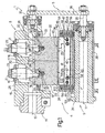
Figure 1 shows a schematic axial section, with parts removed for clarity, of a first preferred embodiment of the rotary ultrasound sealing assembly according to the present invention; -
Figure 2 shows a section along line II--II inFigure 1 ; -
Figure 3 shows a section along line III-III inFigure 1 ; -
Figure 4 shows a section along line IV-IV inFigure 1 ; -
Figure 5 shows a cross section of a first variation of the rotary ultrasound sealing assembly inFigure 1 ; -
Figure 6 shows a cross section of a second variation of the rotary ultrasound sealing assembly inFigure 1 ; -
Figure 7 shows a cross section of a third variation of the rotary ultrasound sealing assembly inFigure 1 ; -
Figure 8 shows the same section as inFigure 3 , but of a second embodiment. - Number 1 in
Figure 2 indicates as a whole an FFS machine, wherein a continuoustubular strip 2, housing an orderly succession ofproducts 3, is fed in known manner (not shown) along a feed path P extending through asealing station 4, where machine 1 comprises a rotaryultrasound sealing assembly 5 for closingtubular strip 2 along sealing areas 6 crosswise to the axis oftubular strip 2 and located at respective portions oftubular strip 2 between respective pairs ofadjacent products 3, and for cuttingtubular strip 2 along sealing areas 6 to form a succession of sealedwrappings 7 containingrespective products 3. -
Rotary assembly 5 comprises tworotors parallel axes sealing station 4, and have respectivecylindrical pitch surfaces - The
rotary sealing assembly 5 shown inFigure 1 is particularly suitable for relatively widetubular strips 2, androtor 8 comprises adrive shaft 14 coaxial withaxis 10 and fitted on its free end with asleeve 15, through which are formed two diametrical throughopenings 16 separated by atransverse partition 17, which terminates short ofaxis 10 so thatopenings 16 communicate with a single substantiallyrectangular opening 18, an outer edge of which,opposite openings 16, is defined by aring 19. Each opening 16 is engaged by a respectiveultrasound sealing device 20, which projects radially outwards fromsleeve 15 through opening 18 andring 19, and is locked to sleeve 15 byring 19. - Each
sealing device 20 comprises an activating device 21 - which may be a converter, a booster, or a pack of ceramic piezoelectric plates - and asonotrode 22 arranged in series along arespective axis 23 which is radial with respect tosleeve 15. Sonotrode 22 comprises a taperinghorn 24 having a free end surface defining anactive surface 25 ofrelative sealing device 20; and acounterweight 26, which is coaxial withhorn 24 alongrespective axis 23, and has, along arespective end surface 27 facing respective activatingdevice 21, acavity 28 coaxial withaxis 10 and bounded by abottom surface 29. Activatingdevice 21 is connected tosonotrode 22 by a threadedappendix 30, which projects, coaxially withaxis 10, from anend surface 31 of activatingdevice 21, and engages a threadedhole 32 formed throughbottom surface 29; .and activatingdevice 21 is partly inserted insidecavity 28, so thatfree surface 31contacts bottom surface 29. -
Sealing device 20 is connected toring 19 by aflange 33 integral withsonotrode 22 and extending outwards fromsonotrode 22, close to the relative nodal surface (not shown). - As shown in
Figure 1 ,rotor 9 ofrotary sealing assembly 5 comprises atubular drive shaft 34 coaxial withaxis 11, and inside a free end of which apin 35 is mounted for rotation and connected, by aspacer plate 36, to asimilar pin 37 mounted for rotation inside the free end ofsleeve 15, to keepsleeve 15 and driveshaft 34 parallel to each other. -
Rotor 9 also comprises asleeve 38 fitted to driveshaft 34, facingsleeve 15, and having anaxial rib 39, in turn having alongitudinal slot 40, which defines, onrib 39, alongitudinal fork 41 engaged by an inner portion of ablade 42, which extends longitudinally alongaxial rib 39 by a length equal to at least twice the longitudinal dimension of asonotrode 22, and has an outer portion projecting radially fromfork 41 and having acutting edge 43 parallel toaxis 11. As shown inFigures 1 and3 , the radial position ofblade 42 is fixed rigidly torotor 9 alonglongitudinal fork 41, and is adjusted by a known adjusting andfastening device 44 comprising twobolts 45 extending through respective holes formed throughfork 41, and respectivelongitudinal slots 46 formed throughblade 42. -
Rotor 9 also comprises oneanvil 47 cooperating with bothsonotrodes 22, and of a length, measured parallel toaxes sonotrodes 22.Anvil 47 is substantially cup-shaped with itsconcavity facing axis 11, and comprises atop wall 48 parallel toaxis 11, bounded externally by agrooved contrast surface 49, and having alongitudinal slot 50 engaged in radially sliding manner byblade 42; and twolateral walls 51 defining between them agroove 52 communicating withslot 50 and engaged in radially sliding manner byaxial rib 39. - As shown in
Figures 1 and4 ,anvil 47 has twolongitudinal end portions 53, each of which projects from the respective longitudinal end ofblade 42, and defines arelative chamber 54 closed outwardly by anend wall 55, open towardsaxis 11, and housing elastic means 56 defined by two respective metalhelical springs 56. Other elastic means may be used, of other than helical shape and made, for example, of music wire. Springs 56 are located side by side in respective substantially radial positions, and are compressed betweenend wall 55 and the outer surface ofsleeve 38. - As shown in
Figures 1 and2 , the radial position ofanvil 47 is adjusted by a known eccentric adjusting andfastening device 57 comprising twobolts 58, each of which extends throughrespective holes 59 formed throughlateral walls 51, and comprises a centraleccentric portion 60 which engages, radially loosely, twoholes 61 formed throughfork 41, and a hole 62 formed throughblade 42. - Operation of
rotary sealing assembly 5 is easily deducible from the foregoing description, with no further explanation required. - It should be pointed out, however, that, outside
sealing station 4, by virtue of the adjustment by adjusting andfastening device 44 and the thrust exerted bysprings 56, the slack betweeneccentric portion 60 ofbolts 58 andholes 61 inlongitudinal fork 41 is located entirely on the opposite side ofeccentric portion 60 to that facingaxis 11; whereas, atsealing station 4, the slack betweeneccentric portion 60 ofbolts 58 andholes 61 inlongitudinal fork 41 is shifted in opposition tosprings 56 and by virtue ofcontrast surface 49 contactingactive surfaces 25 ofsonotrodes 22, withtubular strip 2 in between - to the side ofeccentric portion 60 facingaxis 11, thus "elastically"coupling sonotrodes 22 andanvil 47. - In a second embodiment shown in
Figure 8 ,blade 42 is fixed elastically, as opposed to rigidly, torotor 9, by being fixed rigidly toanvil 47, which haselastic means 56 interposed betweenanvil 47 andrelative rotor 9. In this case too,blade 42 is adjusted by means of a known adjusting andfastening device 44 comprising twobolts 45 extending through respective holes formed throughanvil 47, and respectivelongitudinal slots 46 formed throughblade 42. - In connection with the above, it should be pointed out that, as
sonotrodes 22 and anvil 47 travel throughsealing station 4, the heat transmitted bysonotrodes 22 to anvil 47 in no way damages, and in no way affects, other than marginally, the elastic response of,springs 56. - Also, since the thickness of the material interposed between
sonotrodes 22 andanvil 47 is reduced by plasticization of the material, thus resulting in radial movement ofanvil 47 towardssonotrodes 22, the pressure exchanged betweensonotrodes 22 andanvil 47 atsealing station 4 by virtue ofsprings 56 is also reduced gradually and automatically as plasticization proceeds, thus preventing excessive compression and weakening of the end portions of sealedwrappings 7. - In a variation not shown, and more suitable for narrower tubular strips,
sleeve 15 ofrotor 8 supports asingle sealing device 20, thesonotrode 22 of which has anactive surface 25 of a length, measured parallel toaxes contrast surface 49 ofrelative anvil 47, and slightly greater than the width oftubular strip 2. -
Figures 5 to 7 show, purely by way of non-limiting examples, various structural configurations ofrotors Figure 5 configuration, are identical, and each comprise arespective sleeve 63, from which thesonotrode 22 of arelative sealing device 20, and arespective anvil 47, with arelative blade 42, project radially outwards in diametrically opposite positions. - In the
Figure 6 configuration too,rotors respective sleeve 64, from which the twosonotrodes 22 of twosealing devices 20 project radially outwards in diametrically opposite positions, and twoanvils 47, withrespective blades 42, project radially outwards in diametrically opposite positions and at 90° to the twosonotrodes 22. - In the
Figure 7 configuration,rotors rotor 8 comprises asleeve 65, from which thesonotrodes 22 of foursealing devices 20 project radially outwards and are equally spaced aboutaxis 10; whilerotor 9 comprises adrive shaft 66, from which fouranvils 47, withrespective blades 42, project outwards with the same spacing assonotrodes 22.
Claims (12)
- A rotary ultrasound sealing assembly, which is located at a sealing station (4) to ultrasound seal a continuous tubular strip (2) housing an orderly succession of products (3) and travelling along a feed path (P) extending through the sealing station (4); the rotary sealing assembly (5) comprising:two rotors (8, 9), which are located on opposite sides of the feed path (P), rotate in opposite directions about respective axes (10, 11), and have respective pitch surfaces (12, 13) tangent to each other and to the feed path (P);at least one ultrasound sealing device (20) fitted to at least one of the two rotors (8, 9);a corresponding anvil (47) which cooperates, at the sealing station (4), with the sealing device (20) and is fitted to the other of the two rotors (8, 9); andelastic means (56) interposed between the anvil (47) and the relative rotor (8; 9) to allow an elastic movement between the anvil (47) and the relative rotor (8; 9) along a radial direction perpendicular to the feed path (P);the rotary sealing assembly is characterized in that:a. the elastic means (56) are made of metal;b. the anvil (47) comprises hollow portions (53) open towards the relative rotor (8; 9);c. each hollow portion (53) has an end wall (55) closing it outwardly; andd. each elastic means (56) is housed inside a relative hollow portion (53), and is compressed between the relative rotor (8; 9) and the relative end wall (55).
- A rotary sealing assembly as claimed in Claim 1, wherein the elastic means comprise metal helical springs (56).
- A rotary sealing assembly as claimed in Claim 2, wherein said springs (56) extend substantially radially with respect to the relative rotor (8; 9).
- A rotary sealing assembly as claimed in one of the foregoing Claims, wherein the hollow portions (53) are two in number, and define respective longitudinal end portions of the anvil (47).
- A rotary sealing assembly as claimed in one of the foregoing Claims, and comprising two sealing devices (20) having respective aligned active surfaces (25); the anvil (47) having a contrast surface (49) extending longitudinally to cooperate with both said active surfaces (25) at the sealing station (4).
- A rotary sealing assembly as claimed in one of the foregoing Claims, wherein each said rotor (8;9) comprises a given number of sealing devices (20), and an equal number of anvils (47); each sealing device (20) having a respective active surface (25); each anvil (47) having a respective contrast surface (49); and said active (25) and contrast (49) surfaces defining respective alternating portions equally spaced along the pitch surface (12; 13) of the relative rotor (8; 9).
- A rotary sealing assembly as claimed in Claim 6, wherein, along the pitch surface (12; 13) of the relative rotor (8; 9), each active surface (25) is located diametrically opposite another active surface (25).
- A rotary sealing assembly as claimed in Claim 6, wherein, along the pitch surface (12; 13) of the relative rotor (8; 9), each active surface (25) is located diametrically opposite a contrast surface (49).
- A rotary sealing assembly as claimed in one of Claims 1 to 5, and comprising a number of sealing devices (20) and a number of anvils (47); the sealing devices (20) all being supported by one (8) of the rotors (8, 9), and the anvils (47) all being supported by the other (9) of the rotors (8, 9).
- A rotary sealing assembly as claimed in Claim 1, wherein at least one of the two rotors (8, 9) is fitted rigidly with a blade (42).
- A rotary sealing assembly as claimed in Claim 1, wherein at least one of the two rotors (8, 9) is fitted elastically with a blade (42) fixed rigidly to the anvil (47); the elastic means (56) being interposed between the anvil (47) and the relative rotor (8; 9).
- An FFS machine comprising a rotary ultrasound sealing assembly (5) as claimed in any one of the foregoing Claims.
Applications Claiming Priority (2)
| Application Number | Priority Date | Filing Date | Title |
|---|---|---|---|
| IT000511A ITBO20050511A1 (en) | 2005-07-29 | 2005-07-29 | ULTRASONIC WELDING DEVICE OF CONTINUOUS TUBULAR RIBBONS |
| PCT/IB2005/003890 WO2007012917A1 (en) | 2005-07-29 | 2005-12-28 | Assembly for ultrasound sealing continuous tubular strips |
Publications (2)
| Publication Number | Publication Date |
|---|---|
| EP1919692A1 EP1919692A1 (en) | 2008-05-14 |
| EP1919692B1 true EP1919692B1 (en) | 2013-10-23 |
Family
ID=36088445
Family Applications (1)
| Application Number | Title | Priority Date | Filing Date |
|---|---|---|---|
| EP05850714.6A Expired - Lifetime EP1919692B1 (en) | 2005-07-29 | 2005-12-28 | Assembly for ultrasound sealing continuous tubular strips |
Country Status (8)
| Country | Link |
|---|---|
| US (1) | US20090313944A1 (en) |
| EP (1) | EP1919692B1 (en) |
| JP (1) | JP2009502671A (en) |
| CN (1) | CN101262999B (en) |
| BR (1) | BRPI0520540B8 (en) |
| ES (1) | ES2440478T3 (en) |
| IT (1) | ITBO20050511A1 (en) |
| WO (1) | WO2007012917A1 (en) |
Families Citing this family (29)
| Publication number | Priority date | Publication date | Assignee | Title |
|---|---|---|---|---|
| DE102009000240A1 (en) | 2009-01-15 | 2010-07-22 | Robert Bosch Gmbh | Device for welding and separating packaging materials |
| DE102009002093A1 (en) * | 2009-04-01 | 2010-10-07 | Robert Bosch Gmbh | Device for welding and separating packaging materials |
| DE102009002675A1 (en) | 2009-04-27 | 2010-10-28 | Herrmann Ultraschalltechnik Gmbh & Co. Kg | Ultrasonic sealing device and method for sealing webs of material |
| DE102009026952A1 (en) | 2009-06-16 | 2010-12-23 | Herrmann Ultraschalltechnik Gmbh & Co. Kg | Ultrasonic processing device and transverse seal sonotrode for this purpose |
| DE102009045299A1 (en) | 2009-10-02 | 2011-04-07 | Robert Bosch Gmbh | Apparatus and method for welding and separating packaging materials for packaging |
| IT1398320B1 (en) * | 2010-02-26 | 2013-02-22 | Altopack Spa | PACKAGING MACHINE FOR LONG-FEED PASTA OR SIMILAR PRODUCTS WITH ULTRASONIC TRANSVERSAL WELDING UNIT. |
| DE102010035138A1 (en) * | 2010-08-23 | 2012-02-23 | Maschinenfabrik Spaichingen Gmbh | Ultrasound system for sealing, cutting, perforating and/or embossing of material web in e.g. vertical bagging machine to manufacture e.g. bags, has working gap cyclically formed between rotating anvil and sonotrode |
| DE102010041432A1 (en) | 2010-09-27 | 2012-03-29 | Robert Bosch Gmbh | Ultrasonic resonator |
| DE102010043090A1 (en) * | 2010-10-29 | 2012-05-03 | Robert Bosch Gmbh | Device for separating a packaging material for a packaging |
| JP5999931B2 (en) * | 2011-05-11 | 2016-09-28 | 株式会社イシダ | Horizontal sealing device for packaging machine |
| CN202670170U (en) * | 2011-05-11 | 2013-01-16 | 株式会社石田 | Transverse-sealing device for packaging machine |
| JP5711605B2 (en) * | 2011-05-11 | 2015-05-07 | 株式会社イシダ | Horizontal sealing device for packaging machine |
| JP5058367B1 (en) * | 2011-09-01 | 2012-10-24 | トタニ技研工業株式会社 | Heat seal bar mounting device for bag making machine |
| ITMI20120292A1 (en) * | 2012-02-27 | 2013-08-28 | Altopack Spa | VERTICAL FLOW PACKAGING MACHINE FOR FOOD PASTA OR SIMILAR PRODUCTS WITH ULTRASONIC TRANSVERSAL WELDING UNIT. |
| JP6002494B2 (en) * | 2012-07-30 | 2016-10-05 | 株式会社イシダ | Horizontal sealing device for packaging machine |
| DE102012020694A1 (en) * | 2012-10-22 | 2014-04-24 | Li-Tec Battery Gmbh | pressure device |
| DE102013212722A1 (en) * | 2013-06-28 | 2014-12-31 | Robert Bosch Gmbh | Cutting tool of a joining device for flexible packaging |
| JP6258691B2 (en) * | 2013-12-18 | 2018-01-10 | 株式会社イシダ | Bag making and packaging machine |
| JP6302258B2 (en) * | 2014-01-20 | 2018-03-28 | 株式会社イシダ | Bag making and packaging machine |
| US20170087662A1 (en) * | 2015-09-30 | 2017-03-30 | Branson Ultrasonics Corporation | Tooling For Ultrasonic Tube Sealer For Sealing An End Portion Of A Tube With A Double Seal |
| RS59517B1 (en) * | 2015-12-02 | 2019-12-31 | Swedish Match North Europe Ab | Sealing device |
| EP3181465A1 (en) * | 2015-12-18 | 2017-06-21 | HILTI Aktiengesellschaft | Method and device for filling flexible bag packs |
| CN107042358A (en) * | 2016-02-05 | 2017-08-15 | 叶海龙 | Ultrasonic bonding equipment |
| EP3238918B1 (en) | 2016-04-28 | 2020-06-17 | Tetra Laval Holdings & Finance S.A. | An assembly for producing sealed packaging units |
| CN106184931A (en) * | 2016-08-19 | 2016-12-07 | 安徽御流包装机械有限公司 | Ultrasonic sealing device |
| IT202300002166A1 (en) | 2023-02-09 | 2024-08-09 | Azionaria Costruzioni Macch Automatiche Acma S P A | WELDING DEVICE AND METHOD FOR PRODUCT PACKAGING MACHINES |
| IT202300002163A1 (en) | 2023-02-09 | 2024-08-09 | Azionaria Costruzioni Macch Automatiche Acma S P A | WELDING DEVICE AND METHOD FOR PRODUCT PACKAGING MACHINES. |
| IT202300002169A1 (en) | 2023-02-09 | 2024-08-09 | Azionaria Costruzioni Macch Automatiche Acma S P A | MODULE, DEVICE AND METHOD FOR CHASING WELDING FOR PRODUCT PACKAGING MACHINES |
| WO2025248472A1 (en) | 2024-05-29 | 2025-12-04 | G.D S.P.A. | Welding device and method for product packaging machines |
Family Cites Families (14)
| Publication number | Priority date | Publication date | Assignee | Title |
|---|---|---|---|---|
| US4227959A (en) * | 1978-12-27 | 1980-10-14 | Chatham Manufacturing Company | Sonic or ultrasonic apparatus for simultaneously cutting and seaming sheet material |
| US4391081A (en) * | 1980-09-08 | 1983-07-05 | Hayssen Manufacturing Company | Method of and apparatus for forming, filling and sealing packages |
| US4373982A (en) * | 1980-11-24 | 1983-02-15 | Frito-Lay, Inc. | Ultrasonic sealing apparatus |
| US4534818A (en) * | 1983-12-22 | 1985-08-13 | Frito-Lay, Inc. | Method and apparatus for ultrasonic sealing |
| US4517790A (en) * | 1984-02-27 | 1985-05-21 | Frito-Lay, Inc. | Apparatus and method for ultrasonic sealing of packages |
| US4713132A (en) * | 1986-05-08 | 1987-12-15 | Kimberly-Clark Corporation | Apparatus and method for ultrasonic bonding of a moving web |
| US5421924A (en) * | 1993-12-02 | 1995-06-06 | Paper Converting Machine Company | Apparatus and method for ultrasonic sealing disposable diapers |
| JP3148696B2 (en) * | 1997-10-06 | 2001-03-19 | ウエダアヴァンセ株式会社 | Packaging paper welding equipment |
| JP2002337803A (en) * | 2001-05-14 | 2002-11-27 | Fujimori Kogyo Co Ltd | Continuous bag making and filling machine and method for controlling filling liquid amount of continuous bag making and filling machine |
| US6574944B2 (en) * | 2001-06-19 | 2003-06-10 | Mars Incorporated | Method and system for ultrasonic sealing of food product packaging |
| US6780263B2 (en) * | 2002-08-09 | 2004-08-24 | Illinois Tool Works Inc. | Sealer with continuous motion ultrasonic zipper welding |
| US6786987B2 (en) * | 2002-08-29 | 2004-09-07 | Mars Incorporated | Method and apparatus for performing continuous motion intermittent ultrasonic sealing |
| JP4216637B2 (en) * | 2003-05-08 | 2009-01-28 | 株式会社瑞光 | Wearing device sealing device |
| ITBO20040241A1 (en) * | 2004-04-22 | 2004-07-22 | Azionaria Costruzioni Acma Spa | ROTATING GROUP FOR THE WELDING AND ULTRASOUND OF CONTINUOUS TUBULAR TAPES |
-
2005
- 2005-07-29 IT IT000511A patent/ITBO20050511A1/en unknown
- 2005-12-28 WO PCT/IB2005/003890 patent/WO2007012917A1/en not_active Ceased
- 2005-12-28 JP JP2008523470A patent/JP2009502671A/en active Pending
- 2005-12-28 EP EP05850714.6A patent/EP1919692B1/en not_active Expired - Lifetime
- 2005-12-28 US US11/989,564 patent/US20090313944A1/en not_active Abandoned
- 2005-12-28 ES ES05850714.6T patent/ES2440478T3/en not_active Expired - Lifetime
- 2005-12-28 CN CN200580051551XA patent/CN101262999B/en not_active Expired - Fee Related
- 2005-12-28 BR BRPI0520540A patent/BRPI0520540B8/en not_active IP Right Cessation
Also Published As
| Publication number | Publication date |
|---|---|
| CN101262999B (en) | 2011-02-16 |
| BRPI0520540A2 (en) | 2009-05-19 |
| BRPI0520540B8 (en) | 2018-03-13 |
| CN101262999A (en) | 2008-09-10 |
| US20090313944A1 (en) | 2009-12-24 |
| JP2009502671A (en) | 2009-01-29 |
| WO2007012917A1 (en) | 2007-02-01 |
| BRPI0520540B1 (en) | 2016-06-28 |
| EP1919692A1 (en) | 2008-05-14 |
| ES2440478T3 (en) | 2014-01-29 |
| ITBO20050511A1 (en) | 2005-10-28 |
Similar Documents
| Publication | Publication Date | Title |
|---|---|---|
| US20090313944A1 (en) | Assembly for ultrasound sealing continuous tubular strips | |
| EP3094468B1 (en) | Ultrasound device for sealing and cutting | |
| EP1737733B1 (en) | Rotary unit for ultrasound sealing continuous tubular strips | |
| EP1241098B1 (en) | Ultrasonic transverse sealing device and method for sealing walls of a packaging material filled with a pourable food product | |
| EP2774746B1 (en) | Sonotrode | |
| US3703841A (en) | Rotary shear for wrapping machines | |
| US5548946A (en) | Flowpacker and tool assembly therefor | |
| WO2008102250A1 (en) | Sonotrode for ultrasound welding and cutting packaging units | |
| US11426946B2 (en) | Systems and methods using an ultrasonic transducer and scrubbing horn motion to seal a part | |
| US20120178604A1 (en) | Device and method for welding and separating packaging materials for a package | |
| EP2101985A1 (en) | Ultrasound longitudinal sealing unit for producing continuous tubular strips | |
| CN117794722A (en) | Systems and methods for sealing parts using ultrasonic transducers and scraper tip motion | |
| CN113581551B (en) | Systems and methods for modifying parts using synchronized ultrasonic transducers | |
| EP1241099A1 (en) | Ultrasonic sealing device for sealing packages of pourable food products | |
| US8499811B2 (en) | Device for supporting counter-rotating elements | |
| US12397462B2 (en) | High stiffness booster for ultrasonic welding apparatus with a cutting blade integrated into the horn | |
| US11873128B2 (en) | Systems and methods using an ultrasonic transducer and scrubbing horn motion to seal a part | |
| US9452855B2 (en) | Separating tool of a joining device for flexible packagings | |
| JP2018197116A (en) | Rotary ultrasonic sealer for packaging machines | |
| EP4596157A1 (en) | Ultrasonic horn with flat ultrasonic booster for increased stiffness | |
| JP2023116340A (en) | Rotary-type seal device | |
| HK1156000A (en) | Sealing jaw for producing sealed packages of a food product |
Legal Events
| Date | Code | Title | Description |
|---|---|---|---|
| PUAI | Public reference made under article 153(3) epc to a published international application that has entered the european phase |
Free format text: ORIGINAL CODE: 0009012 |
|
| 17P | Request for examination filed |
Effective date: 20080229 |
|
| AK | Designated contracting states |
Kind code of ref document: A1 Designated state(s): AT BE BG CH CY CZ DE DK EE ES FI FR GB GR HU IE IS IT LI LT LU LV MC NL PL PT RO SE SI SK TR |
|
| 17Q | First examination report despatched |
Effective date: 20100407 |
|
| DAX | Request for extension of the european patent (deleted) | ||
| GRAP | Despatch of communication of intention to grant a patent |
Free format text: ORIGINAL CODE: EPIDOSNIGR1 |
|
| INTG | Intention to grant announced |
Effective date: 20130507 |
|
| GRAS | Grant fee paid |
Free format text: ORIGINAL CODE: EPIDOSNIGR3 |
|
| GRAA | (expected) grant |
Free format text: ORIGINAL CODE: 0009210 |
|
| RIN1 | Information on inventor provided before grant (corrected) |
Inventor name: BOLDRINI, FULVIO Inventor name: GHIOTTI, ROBERTO Inventor name: POLUZZI, ELENA |
|
| AK | Designated contracting states |
Kind code of ref document: B1 Designated state(s): AT BE BG CH CY CZ DE DK EE ES FI FR GB GR HU IE IS IT LI LT LU LV MC NL PL PT RO SE SI SK TR |
|
| REG | Reference to a national code |
Ref country code: GB Ref legal event code: FG4D |
|
| REG | Reference to a national code |
Ref country code: CH Ref legal event code: EP |
|
| REG | Reference to a national code |
Ref country code: AT Ref legal event code: REF Ref document number: 637296 Country of ref document: AT Kind code of ref document: T Effective date: 20131115 |
|
| REG | Reference to a national code |
Ref country code: IE Ref legal event code: FG4D |
|
| REG | Reference to a national code |
Ref country code: CH Ref legal event code: NV Representative=s name: MOINAS AND SAVOYE SA, CH |
|
| REG | Reference to a national code |
Ref country code: DE Ref legal event code: R096 Ref document number: 602005041661 Country of ref document: DE Effective date: 20131224 |
|
| REG | Reference to a national code |
Ref country code: NL Ref legal event code: T3 |
|
| REG | Reference to a national code |
Ref country code: ES Ref legal event code: FG2A Ref document number: 2440478 Country of ref document: ES Kind code of ref document: T3 Effective date: 20140129 |
|
| REG | Reference to a national code |
Ref country code: AT Ref legal event code: MK05 Ref document number: 637296 Country of ref document: AT Kind code of ref document: T Effective date: 20131023 |
|
| REG | Reference to a national code |
Ref country code: LT Ref legal event code: MG4D |
|
| PG25 | Lapsed in a contracting state [announced via postgrant information from national office to epo] |
Ref country code: LT Free format text: LAPSE BECAUSE OF FAILURE TO SUBMIT A TRANSLATION OF THE DESCRIPTION OR TO PAY THE FEE WITHIN THE PRESCRIBED TIME-LIMIT Effective date: 20131023 Ref country code: SE Free format text: LAPSE BECAUSE OF FAILURE TO SUBMIT A TRANSLATION OF THE DESCRIPTION OR TO PAY THE FEE WITHIN THE PRESCRIBED TIME-LIMIT Effective date: 20131023 Ref country code: FI Free format text: LAPSE BECAUSE OF FAILURE TO SUBMIT A TRANSLATION OF THE DESCRIPTION OR TO PAY THE FEE WITHIN THE PRESCRIBED TIME-LIMIT Effective date: 20131023 Ref country code: IS Free format text: LAPSE BECAUSE OF FAILURE TO SUBMIT A TRANSLATION OF THE DESCRIPTION OR TO PAY THE FEE WITHIN THE PRESCRIBED TIME-LIMIT Effective date: 20140223 |
|
| PG25 | Lapsed in a contracting state [announced via postgrant information from national office to epo] |
Ref country code: LV Free format text: LAPSE BECAUSE OF FAILURE TO SUBMIT A TRANSLATION OF THE DESCRIPTION OR TO PAY THE FEE WITHIN THE PRESCRIBED TIME-LIMIT Effective date: 20131023 Ref country code: CY Free format text: LAPSE BECAUSE OF FAILURE TO SUBMIT A TRANSLATION OF THE DESCRIPTION OR TO PAY THE FEE WITHIN THE PRESCRIBED TIME-LIMIT Effective date: 20131023 Ref country code: AT Free format text: LAPSE BECAUSE OF FAILURE TO SUBMIT A TRANSLATION OF THE DESCRIPTION OR TO PAY THE FEE WITHIN THE PRESCRIBED TIME-LIMIT Effective date: 20131023 |
|
| PG25 | Lapsed in a contracting state [announced via postgrant information from national office to epo] |
Ref country code: PT Free format text: LAPSE BECAUSE OF FAILURE TO SUBMIT A TRANSLATION OF THE DESCRIPTION OR TO PAY THE FEE WITHIN THE PRESCRIBED TIME-LIMIT Effective date: 20140224 |
|
| REG | Reference to a national code |
Ref country code: DE Ref legal event code: R097 Ref document number: 602005041661 Country of ref document: DE |
|
| PG25 | Lapsed in a contracting state [announced via postgrant information from national office to epo] |
Ref country code: EE Free format text: LAPSE BECAUSE OF FAILURE TO SUBMIT A TRANSLATION OF THE DESCRIPTION OR TO PAY THE FEE WITHIN THE PRESCRIBED TIME-LIMIT Effective date: 20131023 |
|
| PG25 | Lapsed in a contracting state [announced via postgrant information from national office to epo] |
Ref country code: PL Free format text: LAPSE BECAUSE OF FAILURE TO SUBMIT A TRANSLATION OF THE DESCRIPTION OR TO PAY THE FEE WITHIN THE PRESCRIBED TIME-LIMIT Effective date: 20131023 Ref country code: SK Free format text: LAPSE BECAUSE OF FAILURE TO SUBMIT A TRANSLATION OF THE DESCRIPTION OR TO PAY THE FEE WITHIN THE PRESCRIBED TIME-LIMIT Effective date: 20131023 Ref country code: CZ Free format text: LAPSE BECAUSE OF FAILURE TO SUBMIT A TRANSLATION OF THE DESCRIPTION OR TO PAY THE FEE WITHIN THE PRESCRIBED TIME-LIMIT Effective date: 20131023 Ref country code: RO Free format text: LAPSE BECAUSE OF FAILURE TO SUBMIT A TRANSLATION OF THE DESCRIPTION OR TO PAY THE FEE WITHIN THE PRESCRIBED TIME-LIMIT Effective date: 20131023 Ref country code: LU Free format text: LAPSE BECAUSE OF FAILURE TO SUBMIT A TRANSLATION OF THE DESCRIPTION OR TO PAY THE FEE WITHIN THE PRESCRIBED TIME-LIMIT Effective date: 20131228 Ref country code: MC Free format text: LAPSE BECAUSE OF FAILURE TO SUBMIT A TRANSLATION OF THE DESCRIPTION OR TO PAY THE FEE WITHIN THE PRESCRIBED TIME-LIMIT Effective date: 20131023 |
|
| PLBE | No opposition filed within time limit |
Free format text: ORIGINAL CODE: 0009261 |
|
| STAA | Information on the status of an ep patent application or granted ep patent |
Free format text: STATUS: NO OPPOSITION FILED WITHIN TIME LIMIT |
|
| REG | Reference to a national code |
Ref country code: IE Ref legal event code: MM4A |
|
| REG | Reference to a national code |
Ref country code: FR Ref legal event code: ST Effective date: 20140829 |
|
| PG25 | Lapsed in a contracting state [announced via postgrant information from national office to epo] |
Ref country code: DK Free format text: LAPSE BECAUSE OF FAILURE TO SUBMIT A TRANSLATION OF THE DESCRIPTION OR TO PAY THE FEE WITHIN THE PRESCRIBED TIME-LIMIT Effective date: 20131023 |
|
| 26N | No opposition filed |
Effective date: 20140724 |
|
| PG25 | Lapsed in a contracting state [announced via postgrant information from national office to epo] |
Ref country code: IE Free format text: LAPSE BECAUSE OF NON-PAYMENT OF DUE FEES Effective date: 20131228 |
|
| REG | Reference to a national code |
Ref country code: DE Ref legal event code: R097 Ref document number: 602005041661 Country of ref document: DE Effective date: 20140724 |
|
| PG25 | Lapsed in a contracting state [announced via postgrant information from national office to epo] |
Ref country code: FR Free format text: LAPSE BECAUSE OF NON-PAYMENT OF DUE FEES Effective date: 20131231 |
|
| PG25 | Lapsed in a contracting state [announced via postgrant information from national office to epo] |
Ref country code: SI Free format text: LAPSE BECAUSE OF FAILURE TO SUBMIT A TRANSLATION OF THE DESCRIPTION OR TO PAY THE FEE WITHIN THE PRESCRIBED TIME-LIMIT Effective date: 20131023 |
|
| PG25 | Lapsed in a contracting state [announced via postgrant information from national office to epo] |
Ref country code: TR Free format text: LAPSE BECAUSE OF FAILURE TO SUBMIT A TRANSLATION OF THE DESCRIPTION OR TO PAY THE FEE WITHIN THE PRESCRIBED TIME-LIMIT Effective date: 20131023 |
|
| PG25 | Lapsed in a contracting state [announced via postgrant information from national office to epo] |
Ref country code: BG Free format text: LAPSE BECAUSE OF FAILURE TO SUBMIT A TRANSLATION OF THE DESCRIPTION OR TO PAY THE FEE WITHIN THE PRESCRIBED TIME-LIMIT Effective date: 20131023 Ref country code: HU Free format text: LAPSE BECAUSE OF FAILURE TO SUBMIT A TRANSLATION OF THE DESCRIPTION OR TO PAY THE FEE WITHIN THE PRESCRIBED TIME-LIMIT; INVALID AB INITIO Effective date: 20051228 |
|
| PG25 | Lapsed in a contracting state [announced via postgrant information from national office to epo] |
Ref country code: GR Free format text: LAPSE BECAUSE OF NON-PAYMENT OF DUE FEES Effective date: 20131023 |
|
| PG25 | Lapsed in a contracting state [announced via postgrant information from national office to epo] |
Ref country code: GR Free format text: LAPSE BECAUSE OF FAILURE TO SUBMIT A TRANSLATION OF THE DESCRIPTION OR TO PAY THE FEE WITHIN THE PRESCRIBED TIME-LIMIT Effective date: 20140124 |
|
| REG | Reference to a national code |
Ref country code: CH Ref legal event code: PFA Owner name: AZIONARIA COSTRUZIONI MACCHINE AUTOMATICHE-A.C, IT Free format text: FORMER OWNER: AZIONARIA COSTRUZIONI MACCHINE AUTOMATICHE-A.C.M.A.-S.P.A., IT |
|
| PG25 | Lapsed in a contracting state [announced via postgrant information from national office to epo] |
Ref country code: IT Free format text: LAPSE BECAUSE OF NON-PAYMENT OF DUE FEES Effective date: 20151228 |
|
| PG25 | Lapsed in a contracting state [announced via postgrant information from national office to epo] |
Ref country code: IT Free format text: LAPSE BECAUSE OF NON-PAYMENT OF DUE FEES Effective date: 20151228 |
|
| PGRI | Patent reinstated in contracting state [announced from national office to epo] |
Ref country code: IT Effective date: 20170710 |
|
| PGFP | Annual fee paid to national office [announced via postgrant information from national office to epo] |
Ref country code: NL Payment date: 20171226 Year of fee payment: 13 |
|
| PGFP | Annual fee paid to national office [announced via postgrant information from national office to epo] |
Ref country code: BE Payment date: 20171227 Year of fee payment: 13 |
|
| PGFP | Annual fee paid to national office [announced via postgrant information from national office to epo] |
Ref country code: ES Payment date: 20180102 Year of fee payment: 13 |
|
| REG | Reference to a national code |
Ref country code: NL Ref legal event code: MM Effective date: 20190101 |
|
| PG25 | Lapsed in a contracting state [announced via postgrant information from national office to epo] |
Ref country code: NL Free format text: LAPSE BECAUSE OF NON-PAYMENT OF DUE FEES Effective date: 20190101 |
|
| REG | Reference to a national code |
Ref country code: BE Ref legal event code: MM Effective date: 20181231 |
|
| PG25 | Lapsed in a contracting state [announced via postgrant information from national office to epo] |
Ref country code: BE Free format text: LAPSE BECAUSE OF NON-PAYMENT OF DUE FEES Effective date: 20181231 |
|
| REG | Reference to a national code |
Ref country code: ES Ref legal event code: FD2A Effective date: 20200205 |
|
| PG25 | Lapsed in a contracting state [announced via postgrant information from national office to epo] |
Ref country code: ES Free format text: LAPSE BECAUSE OF NON-PAYMENT OF DUE FEES Effective date: 20181229 |
|
| P01 | Opt-out of the competence of the unified patent court (upc) registered |
Effective date: 20230529 |
|
| PGFP | Annual fee paid to national office [announced via postgrant information from national office to epo] |
Ref country code: GB Payment date: 20231227 Year of fee payment: 19 |
|
| PGFP | Annual fee paid to national office [announced via postgrant information from national office to epo] |
Ref country code: IT Payment date: 20231220 Year of fee payment: 19 |
|
| PGFP | Annual fee paid to national office [announced via postgrant information from national office to epo] |
Ref country code: DE Payment date: 20231229 Year of fee payment: 19 Ref country code: CH Payment date: 20240102 Year of fee payment: 19 |
|
| REG | Reference to a national code |
Ref country code: DE Ref legal event code: R119 Ref document number: 602005041661 Country of ref document: DE |
|
| REG | Reference to a national code |
Ref country code: CH Ref legal event code: PL |
|
| GBPC | Gb: european patent ceased through non-payment of renewal fee |
Effective date: 20241228 |
|
| PG25 | Lapsed in a contracting state [announced via postgrant information from national office to epo] |
Ref country code: DE Free format text: LAPSE BECAUSE OF NON-PAYMENT OF DUE FEES Effective date: 20250701 |
|
| PG25 | Lapsed in a contracting state [announced via postgrant information from national office to epo] |
Ref country code: GB Free format text: LAPSE BECAUSE OF NON-PAYMENT OF DUE FEES Effective date: 20241228 |
|
| PG25 | Lapsed in a contracting state [announced via postgrant information from national office to epo] |
Ref country code: CH Free format text: LAPSE BECAUSE OF NON-PAYMENT OF DUE FEES Effective date: 20241231 |