EP1919061B1 - Protector mounting apparatus for protector mounted adjacent the windings of a motor - Google Patents
Protector mounting apparatus for protector mounted adjacent the windings of a motor Download PDFInfo
- Publication number
- EP1919061B1 EP1919061B1 EP07254228A EP07254228A EP1919061B1 EP 1919061 B1 EP1919061 B1 EP 1919061B1 EP 07254228 A EP07254228 A EP 07254228A EP 07254228 A EP07254228 A EP 07254228A EP 1919061 B1 EP1919061 B1 EP 1919061B1
- Authority
- EP
- European Patent Office
- Prior art keywords
- protector
- motor
- bracket
- windings
- spacer
- Prior art date
- Legal status (The legal status is an assumption and is not a legal conclusion. Google has not performed a legal analysis and makes no representation as to the accuracy of the status listed.)
- Active
Links
Images


Classifications
-
- H—ELECTRICITY
- H02—GENERATION; CONVERSION OR DISTRIBUTION OF ELECTRIC POWER
- H02K—DYNAMO-ELECTRIC MACHINES
- H02K3/00—Details of windings
- H02K3/46—Fastening of windings on the stator or rotor structure
- H02K3/50—Fastening of winding heads, equalising connectors, or connections thereto
-
- H—ELECTRICITY
- H02—GENERATION; CONVERSION OR DISTRIBUTION OF ELECTRIC POWER
- H02K—DYNAMO-ELECTRIC MACHINES
- H02K11/00—Structural association of dynamo-electric machines with electric components or with devices for shielding, monitoring or protection
- H02K11/20—Structural association of dynamo-electric machines with electric components or with devices for shielding, monitoring or protection for measuring, monitoring, testing, protecting or switching
- H02K11/25—Devices for sensing temperature, or actuated thereby
-
- H—ELECTRICITY
- H02—GENERATION; CONVERSION OR DISTRIBUTION OF ELECTRIC POWER
- H02K—DYNAMO-ELECTRIC MACHINES
- H02K11/00—Structural association of dynamo-electric machines with electric components or with devices for shielding, monitoring or protection
- H02K11/20—Structural association of dynamo-electric machines with electric components or with devices for shielding, monitoring or protection for measuring, monitoring, testing, protecting or switching
- H02K11/27—Devices for sensing current, or actuated thereby
Definitions
- This invention relates to a motor having a thermal and/or current sensing protector for protecting the motor from damage, and more particularly to apparatus for attaching such a protector adjacent the windings of the motor.
- An electric motor often includes a protector capable of shutting down the motor before it is damaged due to an abnormality such as excessive heat.
- a typical protector is electrically connected to the winding and is adapted to break the current through the winding when the protector senses excessive temperature and/or current in the winding.
- Protectors may be "on-winding" protectors, which are mounted directly on the windings, or “off-winding” protectors, which are mounted in a position remote from the windings. It is often beneficial to use on-winding protectors so that the thermal sensor is more responsive to changes in temperature in the windings. By measuring the temperature at the windings, e.g., without a significant gap between the windings and the sensor, the protector can respond more quickly to break current when the windings overheat.
- An example of an "on-winding" protector can be found in U.S. Patent No. 5,723,992 , Compressor overload holder and method of mounting same.
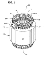
- Fig. 1 is a front perspective of a portion of a motor of one embodiment.
- Fig. 2 is an enlarged front elevation of the portion of the motor shown in Fig. 1 .
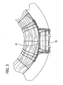
- Fig. 3 is an enlarged top view of the motor.
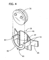
- Fig. 4 is an exploded view of the bracket and protector, the wires of the protector being omitted.
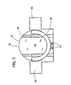
- Fig. 5 is a front perspective of the bracket.
- Fig. 6 is a rear perspective of the bracket.
- a motor of one embodiment of the invention is generally designated 11.
- the motor generally includes a stator 13 including stator core 14 having slots 15, and windings 17 having wire extending through the slots.
- the windings 17 include end turns 21 extending from the slots 15.
- the end turns 21 form a coil generally designated 23 on each side of the stator core 14.
- Each coil 23 has a top or axial end 25 and a radially facing side 27. It is understood that orientation terms such as “top” and the like used herein refer only to the orientation as depicted in the drawings and are not meant to be limiting in any way.
- a fastening system generally designated 29, which may include lacing, cable ties, straps, or any combination thereof, is used to hold the coil together.
- the fastening system 29 of this embodiment includes lacing extending over each coil 23 and between the winding wire 19 extending from the slots 15.
- the rotor and housing are omitted and it will be understood that many different types of rotors and housings are suitable for use with this invention. More generally, it should be understood that a variety of motor configurations can be used within the scope of this invention.
- the motor includes a protector 31 and bracket generally designated 33 mounted adjacent the coil 23 of the windings 17.
- the protector 31 is electrically connected to the windings 17.
- the protector 31 is mounted on the outward side 27 of the coils 23, but may be mounted elsewhere on the coil or windings.
- the bracket 33 is generally sized and shaped to receive the protector 31, and spaces the protector from the coil 23 of the windings 17 to reduce heat transfer from the windings to the protector. More particularly, and with reference to Figs. 3-6 , the bracket 33 of this embodiment includes a spacer 41 having an inwardly facing or back surface 43 mounted against the coils 23, and a front surface 45 in contact with, or adjacent, the protector 31. The back surface 43 is curved to conform to the curvature of the coil 23.
- the front surface 45 of the spacer 41 optionally includes ribs 47 extending therefrom and in contact with the protector 31. The ribs 47 serve to further space the protector 31 from the windings 17, to allow gas to flow between the protector and the front surface 45. This gas may help to cool the protector 31. Note the ribs 47 may taper both in height and in width as shown, the taper helping to retain the protector 31 as described below.
- the spacer 41 of this embodiment has a thickness of between about 0.07 and about 0.20 inches, or more particularly between about 0.08 and about 0.10 inches (excluding the thickness of the ribs). However, the thickness can be increased above 0.20 in other applications to make the protector 31 less sensitive to the temperature of the windings 17.
- Arms 51 extend from the front surface 45 of the spacer 41, the arms being spaced apart to promote passage of gas between the arms and thereby promote cooling of the protector 31. As viewed in Figs. 2 and 5 , the arms 51 are generally disposed at the three, six and nine o'clock positions. The arms 51 have a generally arcuate shape to conform to the shape of the protector 31, and each extends along an arc of, for example, 10-20 degrees.
- an arcuate flange or retainer 55 is disposed at distal ends of the arms 51.
- the retainer 55 extends continuously over an arc of more than 180 degrees, e.g., about 212 degrees.
- the arms 51 have a height somewhat greater than the height of the protector 31 so that the retainer 55 extends over an outer surface of the protector.
- the protector 31 is captured in the pocket formed by the retainer 55, the arms 51 and the front surface 45 of the spacer 41.
- the tapering of the ribs 47 may also aid in forming a snug fit of the protector 31 in the bracket 33.
- fingers 61 extend downwardly from one of the arms 51.
- the fingers 61 are disposed between the protector 31 and the stator core 14 to prevent the protector from contacting the stator core.
- the fingers 61 may also serve to locate the protector 31 relative to the core 14.
- the bracket 33 may also include flaps 65 extending laterally from the spacer 41 to facilitate holding the bracket and protector 31 on the coil 23.
- the lacing can extend over the flaps 65 to secure the bracket 33 and protector 31 on the coil 23.
- the flaps 65 may optionally include slots (not shown) to facilitate securing the bracket 33 on the coil 23.
- the bracket 33 of this embodiment is an integral, single piece of electrically insulating, non-metallic material, e.g., a plastic material such as nylon.
- the bracket 33 may alternatively include multiple pieces. Note that in some embodiments, the material is chosen to withstand a corrosive or chemical-laden environment.
- the motor 11, may for example, be a hermetic compressor motor.
- the motor 11 may include chemicals therein that will contact the protector 31 and bracket 33, so that both are made to withstand contact with such chemicals.
- the protector 31 is of the type that senses current and temperature and is adapted to cut power to the motor 11 in response to excessive heat or a current abnormality. However, it is contemplated that the protector 31 only senses either temperature or current.
- the protector 31 of this embodiment is "in-line", and includes a bi-metal detector for sensing temperature and current.
- the thickness of the spacer adds an additional variable or "knob" that an engineer can manipulate in a particular motor.
- a cost-effective protector or alternatively, a sensor/controller arrangement, that satisfies the disparate requirements for motor protection.
- the protector must sufficiently protect against current abnormalities (e.g., in "locked rotor” mode) and against extreme temperatures (e.g., running mode). In these applications, it is difficult for the protector to satisfy both requirements.
- the thickness of the spacer can be manipulated to make the protector less temperature sensitive, which can make the difference in satisfying disparate motor protection requirements. In other words, a protector that previously did not satisfy the requirements now does with an embodiment of this invention.
- embodiments of the invention can save time and money that would otherwise be spent on development of specialized protectors and/or alternatives such as separate sensors and controllers. It will be understood that compressor applications are merely one example where the invention can provide cost-effective benefits, and many other applications are contemplated.
Landscapes
- Engineering & Computer Science (AREA)
- Power Engineering (AREA)
- Microelectronics & Electronic Packaging (AREA)
- Insulation, Fastening Of Motor, Generator Windings (AREA)
Description
- This invention relates to a motor having a thermal and/or current sensing protector for protecting the motor from damage, and more particularly to apparatus for attaching such a protector adjacent the windings of the motor.
- An electric motor often includes a protector capable of shutting down the motor before it is damaged due to an abnormality such as excessive heat. A typical protector is electrically connected to the winding and is adapted to break the current through the winding when the protector senses excessive temperature and/or current in the winding.
- Protectors may be "on-winding" protectors, which are mounted directly on the windings, or "off-winding" protectors, which are mounted in a position remote from the windings. It is often beneficial to use on-winding protectors so that the thermal sensor is more responsive to changes in temperature in the windings. By measuring the temperature at the windings, e.g., without a significant gap between the windings and the sensor, the protector can respond more quickly to break current when the windings overheat. An example of an "on-winding" protector can be found in
U.S. Patent No. 5,723,992 , Compressor overload holder and method of mounting same. - In some cases, however, mounting the protector directly on the windings may make the sensor over-sensitive to changes in temperature in the windings. Moreover, while the properties of the protector may be changed to try to make the sensor less sensitive, applicants have discovered cases where no protector is suitable due to the proximity of the protector to the windings. In some applications, the protector will "open" or "trip" prematurely so that, for example, the motor will fail the Underwriters Laboratory Maximum Carry Current (ULMCC) test. While "off-winding" protectors or sensor/controller arrangements may be used, applicants have found these are not always a satisfactory, cost-effective solution.
- The invention is defined in the independent claim 1. Further embodiments of the invention are subject of the dependent claims.
-
Fig. 1 is a front perspective of a portion of a motor of one embodiment. -
Fig. 2 is an enlarged front elevation of the portion of the motor shown inFig. 1 . -
Fig. 3 is an enlarged top view of the motor. -
Fig. 4 is an exploded view of the bracket and protector, the wires of the protector being omitted. -
Fig. 5 is a front perspective of the bracket. -
Fig. 6 is a rear perspective of the bracket. - Corresponding reference characters indicate corresponding parts throughout the drawings.
- Referring to
Fig. 1 , a motor of one embodiment of the invention is generally designated 11. The motor generally includes astator 13 includingstator core 14 havingslots 15, andwindings 17 having wire extending through the slots. Thewindings 17 include end turns 21 extending from theslots 15. The end turns 21 form a coil generally designated 23 on each side of thestator core 14. Eachcoil 23 has a top oraxial end 25 and a radially facingside 27. It is understood that orientation terms such as "top" and the like used herein refer only to the orientation as depicted in the drawings and are not meant to be limiting in any way. A fastening system generally designated 29, which may include lacing, cable ties, straps, or any combination thereof, is used to hold the coil together. Thefastening system 29 of this embodiment includes lacing extending over eachcoil 23 and between the winding wire 19 extending from theslots 15. For clarity, the rotor and housing are omitted and it will be understood that many different types of rotors and housings are suitable for use with this invention. More generally, it should be understood that a variety of motor configurations can be used within the scope of this invention. - Referring now to
Figs. 1-4 , the motor includes aprotector 31 and bracket generally designated 33 mounted adjacent thecoil 23 of thewindings 17. Theprotector 31 is electrically connected to thewindings 17. As shown, theprotector 31 is mounted on theoutward side 27 of thecoils 23, but may be mounted elsewhere on the coil or windings. - The
bracket 33 is generally sized and shaped to receive theprotector 31, and spaces the protector from thecoil 23 of thewindings 17 to reduce heat transfer from the windings to the protector. More particularly, and with reference toFigs. 3-6 , thebracket 33 of this embodiment includes aspacer 41 having an inwardly facing or back surface 43 mounted against thecoils 23, and afront surface 45 in contact with, or adjacent, theprotector 31. The back surface 43 is curved to conform to the curvature of thecoil 23. Thefront surface 45 of thespacer 41 optionally includesribs 47 extending therefrom and in contact with theprotector 31. Theribs 47 serve to further space theprotector 31 from thewindings 17, to allow gas to flow between the protector and thefront surface 45. This gas may help to cool theprotector 31. Note theribs 47 may taper both in height and in width as shown, the taper helping to retain theprotector 31 as described below. - The
spacer 41 of this embodiment has a thickness of between about 0.07 and about 0.20 inches, or more particularly between about 0.08 and about 0.10 inches (excluding the thickness of the ribs). However, the thickness can be increased above 0.20 in other applications to make theprotector 31 less sensitive to the temperature of thewindings 17. -
Arms 51 extend from thefront surface 45 of thespacer 41, the arms being spaced apart to promote passage of gas between the arms and thereby promote cooling of theprotector 31. As viewed inFigs. 2 and5 , thearms 51 are generally disposed at the three, six and nine o'clock positions. Thearms 51 have a generally arcuate shape to conform to the shape of theprotector 31, and each extends along an arc of, for example, 10-20 degrees. - In this embodiment, an arcuate flange or
retainer 55 is disposed at distal ends of thearms 51. Theretainer 55 extends continuously over an arc of more than 180 degrees, e.g., about 212 degrees. Thearms 51 have a height somewhat greater than the height of theprotector 31 so that theretainer 55 extends over an outer surface of the protector. Thus, theprotector 31 is captured in the pocket formed by theretainer 55, thearms 51 and thefront surface 45 of thespacer 41. Note that the tapering of theribs 47 may also aid in forming a snug fit of theprotector 31 in thebracket 33. - As viewed in
Figs. 2 and5 ,fingers 61 extend downwardly from one of thearms 51. Thefingers 61 are disposed between theprotector 31 and thestator core 14 to prevent the protector from contacting the stator core. Thefingers 61 may also serve to locate theprotector 31 relative to thecore 14. - The
bracket 33 may also includeflaps 65 extending laterally from thespacer 41 to facilitate holding the bracket andprotector 31 on thecoil 23. For example, the lacing can extend over theflaps 65 to secure thebracket 33 andprotector 31 on thecoil 23. Theflaps 65 may optionally include slots (not shown) to facilitate securing thebracket 33 on thecoil 23. - The
bracket 33 of this embodiment is an integral, single piece of electrically insulating, non-metallic material, e.g., a plastic material such as nylon. Thebracket 33 may alternatively include multiple pieces. Note that in some embodiments, the material is chosen to withstand a corrosive or chemical-laden environment. Themotor 11, may for example, be a hermetic compressor motor. Themotor 11 may include chemicals therein that will contact theprotector 31 andbracket 33, so that both are made to withstand contact with such chemicals. - In one embodiment, the
protector 31 is of the type that senses current and temperature and is adapted to cut power to themotor 11 in response to excessive heat or a current abnormality. However, it is contemplated that theprotector 31 only senses either temperature or current. Theprotector 31 of this embodiment is "in-line", and includes a bi-metal detector for sensing temperature and current. - The thickness of the spacer adds an additional variable or "knob" that an engineer can manipulate in a particular motor. In some more challenging compressor applications, it has been extremely difficult to create a cost-effective protector, or alternatively, a sensor/controller arrangement, that satisfies the disparate requirements for motor protection. For example, the protector must sufficiently protect against current abnormalities (e.g., in "locked rotor" mode) and against extreme temperatures (e.g., running mode). In these applications, it is difficult for the protector to satisfy both requirements. With this invention, the thickness of the spacer can be manipulated to make the protector less temperature sensitive, which can make the difference in satisfying disparate motor protection requirements. In other words, a protector that previously did not satisfy the requirements now does with an embodiment of this invention. Accordingly, embodiments of the invention can save time and money that would otherwise be spent on development of specialized protectors and/or alternatives such as separate sensors and controllers. It will be understood that compressor applications are merely one example where the invention can provide cost-effective benefits, and many other applications are contemplated.
- When introducing elements of embodiments, the articles "a", "an", "the" and "said" are intended to mean that there are one or more of the elements. The terms "comprising", "including" and "having" are intended to be inclusive and mean that there may be additional elements other than the listed elements. Moreover, the use of "top" and "bottom", "front" and "rear", "above" and "below" and variations of these and other terms of orientation is made for convenience, but does not require any particular orientation of the components.
- It is intended that all matter contained in the above description or shown in the accompanying drawings shall be interpreted as illustrative and not in a limiting sense. Further, all dimensional information set forth herein is exemplary and is not intended to limit the scope of the invention unless stated otherwise.
Claims (9)
- A motor 11 comprising a stator core 14, windings 17 extending through the stator core 14, the windings 17 forming a coil 23, a protector 31 electrically connected to the windings 17, and a bracket 33 mounting the protector 31 on the coil 23, the bracket 33 including a spacer 41 adjacent the coil 23, the bracket 33 being characterized by an arcuate retainer 55 spaced from the spacer 41, and a plurality of arms 51 extending between the spacer 41 and the arcuate retainer 55, the arms being spaced apart to promote cooling of the protector, wherein the protector 31 is received in a pocket formed by the arms 51, retainer 55, and spacer 41 and the protector 31 is separated from the coil 23 by the spacer 41 to reduce heat transfer from the windings 17 to the protector 31.
- The motor 11 of claim 1 wherein the spacer 41 of the bracket 33 has a thickness of between about 0.070 and about 0.200 inches, about 0.178 and about 0.508 cm.
- The motor 11 of claim 2 wherein the bracket 33 is a single piece of electrically insulating material.
- The motor 11 of claim 3 wherein the bracket 33 is made of a plastic material.
- The motor 11 of claim 1 wherein the bracket 33 has first, second and third arms 51, the first and second arms 51 being disposed on opposite sides of the bracket 33.
- The motor 11 of claim 5 further comprising fingers extending downwardly from the third arm, the fingers disposed between the protector and the stator core to prevent the protector from contacing the stator core.
- The motor 11 of claim 6 wherein the bracket 33 includes flaps 65 extending from the spacer 41 to facilitate holding the bracket 33 and protector 31 on the coil 23.
- The motor 11 of claim 1 wherein the protector 31 is operable to sense temperature and current and is adapted to stop the motor 11 in case of either excess temperature or a current abnormality.
- The motor 11 of claim 1 wherein the protector 31 is mounted on a side 27 of the coil 23.
Applications Claiming Priority (1)
| Application Number | Priority Date | Filing Date | Title |
|---|---|---|---|
| US11/554,907 US8492943B2 (en) | 2006-10-31 | 2006-10-31 | Protector mounting apparatus for protector mounted adjacent the windings of a motor |
Publications (3)
| Publication Number | Publication Date |
|---|---|
| EP1919061A2 EP1919061A2 (en) | 2008-05-07 |
| EP1919061A3 EP1919061A3 (en) | 2008-08-13 |
| EP1919061B1 true EP1919061B1 (en) | 2012-06-27 |
Family
ID=39092142
Family Applications (1)
| Application Number | Title | Priority Date | Filing Date |
|---|---|---|---|
| EP07254228A Active EP1919061B1 (en) | 2006-10-31 | 2007-10-25 | Protector mounting apparatus for protector mounted adjacent the windings of a motor |
Country Status (3)
| Country | Link |
|---|---|
| US (1) | US8492943B2 (en) |
| EP (1) | EP1919061B1 (en) |
| CN (1) | CN201163737Y (en) |
Families Citing this family (5)
| Publication number | Priority date | Publication date | Assignee | Title |
|---|---|---|---|---|
| JP4751942B2 (en) * | 2009-06-17 | 2011-08-17 | アイシン精機株式会社 | Stator |
| US9112396B2 (en) * | 2013-05-07 | 2015-08-18 | Rockwell Automation Technologies, Inc. | Thermostat clamp for electric motors |
| CN114759741B (en) * | 2022-05-17 | 2023-03-17 | 江苏常荣电器股份有限公司 | Mounting structure of high-power overload protector on motor |
| CN116111771B (en) * | 2023-04-13 | 2023-07-04 | 四川富生汽车零部件有限公司 | Connector terminal structure for direct current motor |
| DE102023110802A1 (en) * | 2023-04-26 | 2024-10-31 | Borgwarner Inc. | coil arrangement |
Family Cites Families (35)
| Publication number | Priority date | Publication date | Assignee | Title |
|---|---|---|---|---|
| US2909719A (en) * | 1958-12-17 | 1959-10-20 | Gen Electric | Motor protective means |
| US3131322A (en) * | 1961-03-06 | 1964-04-28 | Gen Motors Corp | Thermostatic overload protector |
| US3200274A (en) * | 1963-03-14 | 1965-08-10 | Wagner Electric Corp | Thermal protection means for an electric motor |
| US3319096A (en) * | 1964-11-16 | 1967-05-09 | Westinghouse Electric Corp | Thermally protected dynamoelectric machine |
| US4328438A (en) * | 1973-04-02 | 1982-05-04 | General Electric Company | Holder for overload protector |
| US3875439A (en) | 1973-09-17 | 1975-04-01 | Gen Electric | Mounting clip for a dynamoelectric machine |
| US4061935A (en) * | 1976-01-05 | 1977-12-06 | Tecumseh Products Company (Compressor) | Overload protector mounting apparatus |
| US4188553A (en) * | 1978-02-08 | 1980-02-12 | A. O. Smith Corporation | Pocket receptacle for securing a sensing element within electrical windings |
| US4181393A (en) * | 1978-03-17 | 1980-01-01 | Amp Incorporated | Interconnecting means for coil windings and overload protector |
| US4236092A (en) * | 1978-06-08 | 1980-11-25 | Copeland Corporation | Compressor motor protection |
| US4376926A (en) * | 1979-06-27 | 1983-03-15 | Texas Instruments Incorporated | Motor protector calibratable by housing deformation having improved sealing and compactness |
| US4313069A (en) * | 1980-02-26 | 1982-01-26 | Westinghouse Electric Corp. | Mounting for thermal protector used in dynamoelectric machine stator windings |
| US4458231A (en) * | 1981-12-14 | 1984-07-03 | Texas Instruments Incorporated | Protector apparatus for dynamoelectric machines |
| US4454493A (en) * | 1982-09-20 | 1984-06-12 | Susumu Ubukata | Hermetical type thermally responsive switch |
| US4476452A (en) * | 1982-09-27 | 1984-10-09 | Texas Instruments Incorporated | Motor protector |
| US4656378A (en) * | 1985-11-12 | 1987-04-07 | Amp Incorporated | Motor stator and connector for making connections to stator windings |
| US4734602A (en) * | 1987-02-24 | 1988-03-29 | American Standard Inc. | Motor protector receptacle for a refrigeration compressor |
| DE8709261U1 (en) * | 1987-07-04 | 1987-08-20 | Licentia Patent-Verwaltungs-Gmbh, 6000 Frankfurt | Electric motor with circuit breaker |
| US4924350A (en) * | 1988-05-17 | 1990-05-08 | Magnetek Universal Mfg, Corporation | Retention clip for a thermal protection sensor |
| US4914329A (en) * | 1988-10-07 | 1990-04-03 | Emerson Electric Co. | Ventilation air flow block in an electric motor |
| US4866408A (en) * | 1988-10-28 | 1989-09-12 | Texas Instruments Incorporated | Multiphase motor protector apparatus |
| US5367282A (en) * | 1992-07-21 | 1994-11-22 | Texas Instruments Incorporated | Electric motor protector sensor |
| US5852338A (en) * | 1997-02-03 | 1998-12-22 | General Electric Company | Dynamoelectric machine and method for manufacturing same |
| US5723922A (en) * | 1994-05-26 | 1998-03-03 | Tecumseh Products | Compressor overload holder and method of mounting same |
| US5684347A (en) * | 1995-06-07 | 1997-11-04 | General Electric Company | Mounting clip for a motor protector |
| US5723992A (en) | 1995-10-19 | 1998-03-03 | Aspec Technology, Inc. | Low leakage output driver circuit which can be utilized in a multi-voltage source |
| CA2208910C (en) * | 1996-07-04 | 2001-11-06 | Ubukata Industries Co., Ltd. | Thermal protector for electric motors |
| US6410041B1 (en) * | 1998-04-28 | 2002-06-25 | Trustees Of Tufts College | Culturing cells in presence of amphipathic weak bases and/or cations and multiple drug resistance inhibitor containing reserpine |
| JP2000156141A (en) * | 1998-11-17 | 2000-06-06 | Texas Instr Japan Ltd | Motor protector |
| US6315528B1 (en) * | 1999-05-27 | 2001-11-13 | Scroll Technologies | Terminal connection in small area of scroll compressor and method for carrying out same |
| US6674620B2 (en) * | 2000-12-04 | 2004-01-06 | Texas Instruments Incorporated | Hermetic single phase motor protector |
| US6498560B2 (en) | 2001-03-23 | 2002-12-24 | Emerson Electric Co. | Protector assembly and method for electrically insulating a thermally responsive protector from a motor winding of an electric motor |
| US6496560B1 (en) * | 2001-11-21 | 2002-12-17 | Koninklijke Philips Electronics, N.V. | Motion correction for perfusion measurements |
| KR200296482Y1 (en) * | 2002-08-27 | 2002-11-23 | 텍사스 인스트루먼트 코리아 주식회사 | Overload protector with improved sealing capability |
| US7038896B2 (en) * | 2002-12-13 | 2006-05-02 | Texas Instruments Incorporated | Solid state motor protector |
-
2006
- 2006-10-31 US US11/554,907 patent/US8492943B2/en active Active
-
2007
- 2007-10-25 EP EP07254228A patent/EP1919061B1/en active Active
- 2007-10-29 CN CNU2007201821025U patent/CN201163737Y/en not_active Expired - Lifetime
Also Published As
| Publication number | Publication date |
|---|---|
| EP1919061A2 (en) | 2008-05-07 |
| EP1919061A3 (en) | 2008-08-13 |
| US20080100184A1 (en) | 2008-05-01 |
| US8492943B2 (en) | 2013-07-23 |
| CN201163737Y (en) | 2008-12-10 |
Similar Documents
| Publication | Publication Date | Title |
|---|---|---|
| US9735659B2 (en) | Electric rotating machine having a thermistor in a gap between U-shaped and odd-shaped coil ends | |
| US9696178B2 (en) | Rotating electrical machine | |
| EP1919061A2 (en) | Protector mounting apparatus for protector mounted adjacent the windings of a motor | |
| EP3166212B1 (en) | Motor | |
| TW472427B (en) | Programmable electric motor and method of assembly | |
| US3131322A (en) | Thermostatic overload protector | |
| US4236092A (en) | Compressor motor protection | |
| JP6658366B2 (en) | Rotating electric machine | |
| CN107534363B (en) | Rotational position detection device for internal combustion engine and rotating electrical machine for internal combustion engine | |
| CN111628615B (en) | Rotary electric machine, temperature detector thereof, and method of manufacturing and protecting the same | |
| JP5840226B2 (en) | Electric motor | |
| US7535136B2 (en) | Protector mounting apparatus for protector mounted on the windings of a motor | |
| KR101755470B1 (en) | Totally enclosed motor | |
| US7501728B2 (en) | Electric machine with a winding support assembly and a measuring system | |
| US6822354B2 (en) | Electric motor | |
| JPH11234964A (en) | Temperature detection structure for motor | |
| WO2024070367A1 (en) | Supercharger | |
| JP2014042402A (en) | Rotary electric machine | |
| JPH08163830A (en) | Protector for hermetic motor compressor | |
| JP2006141185A (en) | Synchronous motor | |
| CN206250893U (en) | Fan motor and the electric product comprising the fan motor | |
| JP3627374B2 (en) | Overheat protection device for electric motor | |
| CN210075008U (en) | Motor and vehicle-mounted device | |
| JPS6120845Y2 (en) | ||
| CN108010821A (en) | Sensitive-type overcurrent protector |
Legal Events
| Date | Code | Title | Description |
|---|---|---|---|
| PUAI | Public reference made under article 153(3) epc to a published international application that has entered the european phase |
Free format text: ORIGINAL CODE: 0009012 |
|
| AK | Designated contracting states |
Kind code of ref document: A2 Designated state(s): AT BE BG CH CY CZ DE DK EE ES FI FR GB GR HU IE IS IT LI LT LU LV MC MT NL PL PT RO SE SI SK TR |
|
| AX | Request for extension of the european patent |
Extension state: AL BA HR MK RS |
|
| PUAL | Search report despatched |
Free format text: ORIGINAL CODE: 0009013 |
|
| AK | Designated contracting states |
Kind code of ref document: A3 Designated state(s): AT BE BG CH CY CZ DE DK EE ES FI FR GB GR HU IE IS IT LI LT LU LV MC MT NL PL PT RO SE SI SK TR |
|
| AX | Request for extension of the european patent |
Extension state: AL BA HR MK RS |
|
| 17P | Request for examination filed |
Effective date: 20090109 |
|
| 17Q | First examination report despatched |
Effective date: 20090212 |
|
| AKX | Designation fees paid |
Designated state(s): AT BE BG CH CY CZ DE DK EE ES FI FR GB GR HU IE IS IT LI LT LU LV MC MT NL PL PT RO SE SI SK TR |
|
| GRAP | Despatch of communication of intention to grant a patent |
Free format text: ORIGINAL CODE: EPIDOSNIGR1 |
|
| GRAS | Grant fee paid |
Free format text: ORIGINAL CODE: EPIDOSNIGR3 |
|
| GRAA | (expected) grant |
Free format text: ORIGINAL CODE: 0009210 |
|
| AK | Designated contracting states |
Kind code of ref document: B1 Designated state(s): AT BE BG CH CY CZ DE DK EE ES FI FR GB GR HU IE IS IT LI LT LU LV MC MT NL PL PT RO SE SI SK TR |
|
| REG | Reference to a national code |
Ref country code: GB Ref legal event code: FG4D |
|
| REG | Reference to a national code |
Ref country code: CH Ref legal event code: EP |
|
| REG | Reference to a national code |
Ref country code: AT Ref legal event code: REF Ref document number: 564635 Country of ref document: AT Kind code of ref document: T Effective date: 20120715 |
|
| REG | Reference to a national code |
Ref country code: IE Ref legal event code: FG4D |
|
| REG | Reference to a national code |
Ref country code: DE Ref legal event code: R096 Ref document number: 602007023569 Country of ref document: DE Effective date: 20120823 |
|
| PG25 | Lapsed in a contracting state [announced via postgrant information from national office to epo] |
Ref country code: LT Free format text: LAPSE BECAUSE OF FAILURE TO SUBMIT A TRANSLATION OF THE DESCRIPTION OR TO PAY THE FEE WITHIN THE PRESCRIBED TIME-LIMIT Effective date: 20120627 Ref country code: SE Free format text: LAPSE BECAUSE OF FAILURE TO SUBMIT A TRANSLATION OF THE DESCRIPTION OR TO PAY THE FEE WITHIN THE PRESCRIBED TIME-LIMIT Effective date: 20120627 Ref country code: FI Free format text: LAPSE BECAUSE OF FAILURE TO SUBMIT A TRANSLATION OF THE DESCRIPTION OR TO PAY THE FEE WITHIN THE PRESCRIBED TIME-LIMIT Effective date: 20120627 |
|
| REG | Reference to a national code |
Ref country code: NL Ref legal event code: VDEP Effective date: 20120627 |
|
| REG | Reference to a national code |
Ref country code: AT Ref legal event code: MK05 Ref document number: 564635 Country of ref document: AT Kind code of ref document: T Effective date: 20120627 |
|
| REG | Reference to a national code |
Ref country code: LT Ref legal event code: MG4D Effective date: 20120627 |
|
| PG25 | Lapsed in a contracting state [announced via postgrant information from national office to epo] |
Ref country code: LV Free format text: LAPSE BECAUSE OF FAILURE TO SUBMIT A TRANSLATION OF THE DESCRIPTION OR TO PAY THE FEE WITHIN THE PRESCRIBED TIME-LIMIT Effective date: 20120627 Ref country code: SI Free format text: LAPSE BECAUSE OF FAILURE TO SUBMIT A TRANSLATION OF THE DESCRIPTION OR TO PAY THE FEE WITHIN THE PRESCRIBED TIME-LIMIT Effective date: 20120627 Ref country code: GR Free format text: LAPSE BECAUSE OF FAILURE TO SUBMIT A TRANSLATION OF THE DESCRIPTION OR TO PAY THE FEE WITHIN THE PRESCRIBED TIME-LIMIT Effective date: 20120928 |
|
| PG25 | Lapsed in a contracting state [announced via postgrant information from national office to epo] |
Ref country code: EE Free format text: LAPSE BECAUSE OF FAILURE TO SUBMIT A TRANSLATION OF THE DESCRIPTION OR TO PAY THE FEE WITHIN THE PRESCRIBED TIME-LIMIT Effective date: 20120627 Ref country code: SK Free format text: LAPSE BECAUSE OF FAILURE TO SUBMIT A TRANSLATION OF THE DESCRIPTION OR TO PAY THE FEE WITHIN THE PRESCRIBED TIME-LIMIT Effective date: 20120627 Ref country code: IS Free format text: LAPSE BECAUSE OF FAILURE TO SUBMIT A TRANSLATION OF THE DESCRIPTION OR TO PAY THE FEE WITHIN THE PRESCRIBED TIME-LIMIT Effective date: 20121027 Ref country code: BE Free format text: LAPSE BECAUSE OF NON-PAYMENT OF DUE FEES Effective date: 20120627 Ref country code: CY Free format text: LAPSE BECAUSE OF FAILURE TO SUBMIT A TRANSLATION OF THE DESCRIPTION OR TO PAY THE FEE WITHIN THE PRESCRIBED TIME-LIMIT Effective date: 20120627 Ref country code: CZ Free format text: LAPSE BECAUSE OF FAILURE TO SUBMIT A TRANSLATION OF THE DESCRIPTION OR TO PAY THE FEE WITHIN THE PRESCRIBED TIME-LIMIT Effective date: 20120627 Ref country code: RO Free format text: LAPSE BECAUSE OF FAILURE TO SUBMIT A TRANSLATION OF THE DESCRIPTION OR TO PAY THE FEE WITHIN THE PRESCRIBED TIME-LIMIT Effective date: 20120627 Ref country code: AT Free format text: LAPSE BECAUSE OF FAILURE TO SUBMIT A TRANSLATION OF THE DESCRIPTION OR TO PAY THE FEE WITHIN THE PRESCRIBED TIME-LIMIT Effective date: 20120627 |
|
| PG25 | Lapsed in a contracting state [announced via postgrant information from national office to epo] |
Ref country code: PL Free format text: LAPSE BECAUSE OF FAILURE TO SUBMIT A TRANSLATION OF THE DESCRIPTION OR TO PAY THE FEE WITHIN THE PRESCRIBED TIME-LIMIT Effective date: 20120627 Ref country code: PT Free format text: LAPSE BECAUSE OF FAILURE TO SUBMIT A TRANSLATION OF THE DESCRIPTION OR TO PAY THE FEE WITHIN THE PRESCRIBED TIME-LIMIT Effective date: 20121029 |
|
| PG25 | Lapsed in a contracting state [announced via postgrant information from national office to epo] |
Ref country code: NL Free format text: LAPSE BECAUSE OF FAILURE TO SUBMIT A TRANSLATION OF THE DESCRIPTION OR TO PAY THE FEE WITHIN THE PRESCRIBED TIME-LIMIT Effective date: 20120627 |
|
| PG25 | Lapsed in a contracting state [announced via postgrant information from national office to epo] |
Ref country code: DK Free format text: LAPSE BECAUSE OF FAILURE TO SUBMIT A TRANSLATION OF THE DESCRIPTION OR TO PAY THE FEE WITHIN THE PRESCRIBED TIME-LIMIT Effective date: 20120627 Ref country code: ES Free format text: LAPSE BECAUSE OF FAILURE TO SUBMIT A TRANSLATION OF THE DESCRIPTION OR TO PAY THE FEE WITHIN THE PRESCRIBED TIME-LIMIT Effective date: 20121008 |
|
| PLBE | No opposition filed within time limit |
Free format text: ORIGINAL CODE: 0009261 |
|
| STAA | Information on the status of an ep patent application or granted ep patent |
Free format text: STATUS: NO OPPOSITION FILED WITHIN TIME LIMIT |
|
| PG25 | Lapsed in a contracting state [announced via postgrant information from national office to epo] |
Ref country code: MC Free format text: LAPSE BECAUSE OF NON-PAYMENT OF DUE FEES Effective date: 20121031 |
|
| REG | Reference to a national code |
Ref country code: CH Ref legal event code: PL |
|
| 26N | No opposition filed |
Effective date: 20130328 |
|
| REG | Reference to a national code |
Ref country code: IE Ref legal event code: MM4A |
|
| REG | Reference to a national code |
Ref country code: DE Ref legal event code: R097 Ref document number: 602007023569 Country of ref document: DE Effective date: 20130328 |
|
| PG25 | Lapsed in a contracting state [announced via postgrant information from national office to epo] |
Ref country code: IE Free format text: LAPSE BECAUSE OF NON-PAYMENT OF DUE FEES Effective date: 20121025 Ref country code: BG Free format text: LAPSE BECAUSE OF FAILURE TO SUBMIT A TRANSLATION OF THE DESCRIPTION OR TO PAY THE FEE WITHIN THE PRESCRIBED TIME-LIMIT Effective date: 20120927 Ref country code: LI Free format text: LAPSE BECAUSE OF NON-PAYMENT OF DUE FEES Effective date: 20121031 Ref country code: CH Free format text: LAPSE BECAUSE OF NON-PAYMENT OF DUE FEES Effective date: 20121031 |
|
| PG25 | Lapsed in a contracting state [announced via postgrant information from national office to epo] |
Ref country code: MT Free format text: LAPSE BECAUSE OF FAILURE TO SUBMIT A TRANSLATION OF THE DESCRIPTION OR TO PAY THE FEE WITHIN THE PRESCRIBED TIME-LIMIT Effective date: 20120627 |
|
| PG25 | Lapsed in a contracting state [announced via postgrant information from national office to epo] |
Ref country code: TR Free format text: LAPSE BECAUSE OF FAILURE TO SUBMIT A TRANSLATION OF THE DESCRIPTION OR TO PAY THE FEE WITHIN THE PRESCRIBED TIME-LIMIT Effective date: 20120627 |
|
| PG25 | Lapsed in a contracting state [announced via postgrant information from national office to epo] |
Ref country code: LU Free format text: LAPSE BECAUSE OF NON-PAYMENT OF DUE FEES Effective date: 20121025 |
|
| PG25 | Lapsed in a contracting state [announced via postgrant information from national office to epo] |
Ref country code: HU Free format text: LAPSE BECAUSE OF FAILURE TO SUBMIT A TRANSLATION OF THE DESCRIPTION OR TO PAY THE FEE WITHIN THE PRESCRIBED TIME-LIMIT Effective date: 20071025 |
|
| REG | Reference to a national code |
Ref country code: FR Ref legal event code: PLFP Year of fee payment: 9 |
|
| REG | Reference to a national code |
Ref country code: FR Ref legal event code: PLFP Year of fee payment: 10 |
|
| REG | Reference to a national code |
Ref country code: FR Ref legal event code: PLFP Year of fee payment: 11 |
|
| REG | Reference to a national code |
Ref country code: FR Ref legal event code: PLFP Year of fee payment: 12 |
|
| PGFP | Annual fee paid to national office [announced via postgrant information from national office to epo] |
Ref country code: IT Payment date: 20191023 Year of fee payment: 13 Ref country code: FR Payment date: 20191025 Year of fee payment: 13 |
|
| PGFP | Annual fee paid to national office [announced via postgrant information from national office to epo] |
Ref country code: GB Payment date: 20191028 Year of fee payment: 13 |
|
| GBPC | Gb: european patent ceased through non-payment of renewal fee |
Effective date: 20201025 |
|
| PG25 | Lapsed in a contracting state [announced via postgrant information from national office to epo] |
Ref country code: FR Free format text: LAPSE BECAUSE OF NON-PAYMENT OF DUE FEES Effective date: 20201031 |
|
| PG25 | Lapsed in a contracting state [announced via postgrant information from national office to epo] |
Ref country code: GB Free format text: LAPSE BECAUSE OF NON-PAYMENT OF DUE FEES Effective date: 20201025 |
|
| PG25 | Lapsed in a contracting state [announced via postgrant information from national office to epo] |
Ref country code: IT Free format text: LAPSE BECAUSE OF NON-PAYMENT OF DUE FEES Effective date: 20201025 |
|
| REG | Reference to a national code |
Ref country code: DE Ref legal event code: R081 Ref document number: 602007023569 Country of ref document: DE Owner name: COPELAND SCROLL COMPRESSORS LP, ST. LOUIS, US Free format text: FORMER OWNER: EMERSON ELECTRIC CO., ST. LOUIS, MO., US Ref country code: DE Ref legal event code: R081 Ref document number: 602007023569 Country of ref document: DE Owner name: COPELAND SCROLL COMPRESSORS LP, LEBANON, US Free format text: FORMER OWNER: EMERSON ELECTRIC CO., ST. LOUIS, MO., US |
|
| REG | Reference to a national code |
Ref country code: DE Ref legal event code: R081 Ref document number: 602007023569 Country of ref document: DE Owner name: COPELAND SCROLL COMPRESSORS LP, ST. LOUIS, US Free format text: FORMER OWNER: COPELAND SCROLL COMPRESSORS LP, LEBANON, MO, US |
|
| PGFP | Annual fee paid to national office [announced via postgrant information from national office to epo] |
Ref country code: DE Payment date: 20250923 Year of fee payment: 19 |