EP1918945A2 - Coil body for inductive elements - Google Patents
Coil body for inductive elements Download PDFInfo
- Publication number
- EP1918945A2 EP1918945A2 EP07117209A EP07117209A EP1918945A2 EP 1918945 A2 EP1918945 A2 EP 1918945A2 EP 07117209 A EP07117209 A EP 07117209A EP 07117209 A EP07117209 A EP 07117209A EP 1918945 A2 EP1918945 A2 EP 1918945A2
- Authority
- EP
- European Patent Office
- Prior art keywords
- bobbin
- terminals
- circuit boards
- winding
- printed circuit
- Prior art date
- Legal status (The legal status is an assumption and is not a legal conclusion. Google has not performed a legal analysis and makes no representation as to the accuracy of the status listed.)
- Withdrawn
Links
Images
Classifications
-
- H—ELECTRICITY
- H01—ELECTRIC ELEMENTS
- H01F—MAGNETS; INDUCTANCES; TRANSFORMERS; SELECTION OF MATERIALS FOR THEIR MAGNETIC PROPERTIES
- H01F5/00—Coils
- H01F5/02—Coils wound on non-magnetic supports, e.g. formers
-
- H—ELECTRICITY
- H01—ELECTRIC ELEMENTS
- H01F—MAGNETS; INDUCTANCES; TRANSFORMERS; SELECTION OF MATERIALS FOR THEIR MAGNETIC PROPERTIES
- H01F27/00—Details of transformers or inductances, in general
- H01F27/28—Coils; Windings; Conductive connections
- H01F27/29—Terminals; Tapping arrangements for signal inductances
-
- H—ELECTRICITY
- H05—ELECTRIC TECHNIQUES NOT OTHERWISE PROVIDED FOR
- H05K—PRINTED CIRCUITS; CASINGS OR CONSTRUCTIONAL DETAILS OF ELECTRIC APPARATUS; MANUFACTURE OF ASSEMBLAGES OF ELECTRICAL COMPONENTS
- H05K1/00—Printed circuits
- H05K1/02—Details
- H05K1/14—Structural association of two or more printed circuits
- H05K1/145—Arrangements wherein electric components are disposed between and simultaneously connected to two planar printed circuit boards, e.g. Cordwood modules
-
- H—ELECTRICITY
- H01—ELECTRIC ELEMENTS
- H01F—MAGNETS; INDUCTANCES; TRANSFORMERS; SELECTION OF MATERIALS FOR THEIR MAGNETIC PROPERTIES
- H01F5/00—Coils
- H01F5/04—Arrangements of electric connections to coils, e.g. leads
- H01F2005/046—Details of formers and pin terminals related to mounting on printed circuits
-
- H—ELECTRICITY
- H01—ELECTRIC ELEMENTS
- H01F—MAGNETS; INDUCTANCES; TRANSFORMERS; SELECTION OF MATERIALS FOR THEIR MAGNETIC PROPERTIES
- H01F27/00—Details of transformers or inductances, in general
- H01F27/02—Casings
- H01F27/027—Casings specially adapted for combination of signal type inductors or transformers with electronic circuits, e.g. mounting on printed circuit boards
-
- H—ELECTRICITY
- H05—ELECTRIC TECHNIQUES NOT OTHERWISE PROVIDED FOR
- H05K—PRINTED CIRCUITS; CASINGS OR CONSTRUCTIONAL DETAILS OF ELECTRIC APPARATUS; MANUFACTURE OF ASSEMBLAGES OF ELECTRICAL COMPONENTS
- H05K2201/00—Indexing scheme relating to printed circuits covered by H05K1/00
- H05K2201/10—Details of components or other objects attached to or integrated in a printed circuit board
- H05K2201/10007—Types of components
- H05K2201/1003—Non-printed inductor
Definitions
- the invention relates to a coil body for inductive components with connections for printed circuit boards, according to the preamble of claim 1.
- the invention further comprises an inductive component with a bobbin according to the invention, as well as a held in the bobbin magnetic core, and at least one winding along a Winding section of the bobbin.
- the invention further comprises a coil assembly with two printed circuit boards and an inductive component with a bobbin according to the invention.
- inductive components such as transformers in which high voltages can occur at least on one side
- require a correspondingly high insulation strength which in turn leads to a corresponding increase in the overall volume.
- power supply units the requirement of reducing the volume of construction is one of the main objectives.
- Power supplies with high supply voltages are particularly difficult to optimize here, as appropriate Distance criteria must be met, so the distance of current-carrying paths can not be arbitrarily reduced.
- it is difficult to reduce the size, in particular in the case of inductive components for example due to a required minimum distance between adjacent terminals ("pins"). Therefore, for example, in transformers, the primary and secondary windings were always executed on the same side.
- Conventional bobbins therefore support only such a construction.
- Claim 1 provides a coil body for inductive components with connections for printed circuit boards, in which connections are provided on opposite sides of the bobbin.
- the terminals are not only executed on one side, but also on the opposite side. This makes it possible to attach the bobbin or the inductive component based thereon between two printed circuit boards.
- the Energy flow thus moves approximately in a transformer with the bobbin of the invention from the input terminals on one of the two circuit boards on the primary DC link on the transformer to the secondary side to the output terminals located there on the second circuit board. The structure can thus be made much more compact.
- the bobbin can also be used simultaneously as a signal transmitting element between the two circuit boards. This does not necessarily have to be the transformer-related signals, since it is also possible to equip the bobbin with additional connecting elements that transmit transformer-independent signals.
- Another advantage of inventive bobbin is the lower crosstalk of signals from the primary side to the secondary side due to the improved spatial separation.
- Claim 2 refers to an inductive component with a bobbin according to the invention, as well as held in the bobbin, magnetic core, and at least one winding along a winding portion of the bobbin, wherein it is provided that the end portions of the at least one winding in the terminals of the bobbin for the production a conductive connection with a circuit board are held.
- the inductive component is a transformer having a primary winding and a secondary winding, wherein the terminals are assigned to one side of the primary winding, and the terminals of the opposite side of the secondary winding. It is advantageous according to claim 4, when the magnetic core is designed as an E-core made of a ferrite.
- Claim 5 relates to a coil assembly having two printed circuit boards and an inductive component with a bobbin according to the invention, wherein the terminals are each connected to one side of the device with one of the circuit boards.
- Claim 6 refers to a power supply, which may also be a switching power supply, with a coil assembly according to the invention, and claim 7 to an inverter.
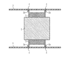
- FIG. 1 shows a schematic representation of a side view of a coil assembly according to the invention.
- Fig. 1 shows a first circuit board 1 and a second circuit board 2, which serve in a conventional manner, the mechanical fastening and the electrical connection of electronic components.
- an inductive component in Fig. 1, about a transformer, arranged, which is fastened via terminals 3 to the circuit boards 1,2.
- the terminals 3 are placed in the illustrated embodiment of solder pins 4, and can be soldered directly to the PCB 1.2. Alternatively, corresponding contact surfaces for surface mounting would be conceivable.
- the terminals 3a define the primary side of the transformer, and the terminals 3b arranged on the opposite side the secondary side. In the terminals 3a, the end portions of the primary winding 5a are held to make a conductive connection with the circuit board 1, and in the terminals 3b, the end portions of the secondary winding 5b for making a conductive connection with the circuit board 2.
- the primary winding 5a and the secondary winding 5b are not distinguishable shown as winding 5 in FIG.
- the windings 5 are enclosed by a magnetic core 6, which is preferably a soft magnetic material, such as a ferrite.
- Ferrites are ferromagnetic ceramics, which are used especially for smaller transformers and higher frequencies.
- amorphous metal strip cores or powder cores Since the change in the magnetic field strength is an essential part of the mode of action of the transformer, a transformer can also transmit more power at an increased frequency of the exciter current. Therefore, with increasing frequency, the number of turns and / or the core volume can decrease without the voltage changing. Thus, a much higher power density is achieved, so that about switching power supplies can be built much smaller.
- the magnetic core 6 is also composed of two E cores. Such a design is particularly suitable for high performance and also has the advantage of using two low-priced standard E cores, instead of a single, larger special design.
- the bobbin is a non-magnetic material, usually made of plastic, existing molding, which receives the magnetic core 6 and the windings 5, they are mechanical stability and, if necessary, also isolated from each other.
- the bobbin also provides the terminals 3, which are provided according to the invention on opposite sides of the bobbin.
- the magnetic core 6 is fixed in the bobbin, and the windings 5 are applied along a winding section of the bobbin.
- the end portions of the windings 5 are then held in the terminals 3 of the bobbin for making a conductive connection with the circuit boards 1,2.
- the energy flow thus moves from the input terminals 3a on the first circuit board 1 via the primary intermediate circuit via the transformer to the secondary side to the output terminals 3b located there on the second printed circuit board 2.
- the improved spatial separation thus enables a reduction in size, in particular for inductive components.
- the packing density of these components can be increased on the circuit boards 1,2 and the construction costs are reduced.
- the component behavior with regard to the insulation resistance of these components is thus increased in a simple manner.
- Particularly advantageous is the use of such coil assembly according to the invention in power supplies, such as switching power supplies, or in inverters.
Abstract
Description
Die Erfindung bezieht sich auf einen Spulenkörper für induktive Bauelemente mit Anschlüssen für Leiterplatten, gemäß dem Oberbegriff von Anspruch 1. Die Erfindung umfasst des Weiteren ein induktives Bauelement mit einem erfindungsgemäßen Spulenkörper, sowie einem im Spulenkörper gehaltenen, magnetischen Kern, und zumindest einer Wicklung entlang eines Wickelabschnittes des Spulenkörpers. Die Erfindung umfasst ferner eine Spulenbaugruppe mit zwei Leiterplatten und einem induktiven Bauelement mit einem erfindungsgemäßen Spulenkörper.The invention relates to a coil body for inductive components with connections for printed circuit boards, according to the preamble of
Durch die Entwicklung immer leistungsfähigerer und kompakterer elektronischer Schaltungen werden zunehmend elektronische Schaltungen auf Leiterplatten verwirklicht, in denen Ströme und/oder Spannungen bei hohen Frequenzen und hoher Leistung geschaltet werden müssen. Die entsprechenden induktiven Komponenten bilden dabei einen wesentlichen Bestandteil solcher Schaltungen, wobei insbesondere die erforderliche Größe des induktiven Bauelements einen wesentlichen Kostenfaktor darstellt, da in der Regel teure Ferritmaterialien erforderlich sind, und außerdem ein großes Bauvolumen auch ein entsprechendes Volumen auf der Leiterplatte einnimmt, was die Packungsdichte verringert.With the development of more and more efficient and compact electronic circuits, electronic circuits are increasingly being realized on printed circuit boards in which currents and / or voltages at high frequencies and high power must be switched. The corresponding inductive components thereby form an integral part of such circuits, in particular, the required size of the inductive component is a significant cost factor, since usually expensive ferrite materials are required, and also a large volume of construction occupies a corresponding volume on the circuit board, which the Packing density reduced.
Des Weiteren ist bei induktiven Bauelementen, etwa Transformatoren, in denen zumindest auf einer Seite hohe Spannungen auftreten können, eine entsprechend hohe Isolationsfestigkeit zu fordern, die dann wiederum zu einer entsprechenden Vergrößerung des Bauvolumens führt. Speziell bei Netzteilen ist die Anforderung einer Reduzierung des Bauvolumens eines der wesentlichen Zielsetzungen. Netzteile mit hohen Versorgungsspannungen sind hier besonders schwierig optimierbar, da entsprechende Distanzkriterien eingehalten werden müssen, also die Distanz stromführender Pfade nicht beliebig verringert werden kann. Dadurch ist insbesondere bei induktiven Komponenten ein Reduzieren der Baugröße schwer möglich, etwa aufgrund eines erforderlichen Mindestabstandes benachbarter Anschlüsse ("Pins"). Daher wurden etwa bei Transformatoren die Primär- und Sekundärwicklungen immer auf der gleichen Seite ausgeführt. Herkömmliche Spulenkörper unterstützen daher auch ausschließlich eine solche Bauweise.Furthermore, inductive components, such as transformers in which high voltages can occur at least on one side, require a correspondingly high insulation strength, which in turn leads to a corresponding increase in the overall volume. Especially with power supply units, the requirement of reducing the volume of construction is one of the main objectives. Power supplies with high supply voltages are particularly difficult to optimize here, as appropriate Distance criteria must be met, so the distance of current-carrying paths can not be arbitrarily reduced. As a result, it is difficult to reduce the size, in particular in the case of inductive components, for example due to a required minimum distance between adjacent terminals ("pins"). Therefore, for example, in transformers, the primary and secondary windings were always executed on the same side. Conventional bobbins therefore support only such a construction.
Des Weiteren ist es bekannt, mehrere Leiterplatten zu verwenden, welche in die Hauptplatine eingesteckt werden. Dadurch wird zwar eine höhere Packungsdichte auf der Hauptplatine erreicht, ein Reduzieren der Baugröße etwa induktiver Bauelemente ist aber auch durch eine solche Maßnahme nicht möglich.Furthermore, it is known to use several circuit boards, which are inserted into the motherboard. As a result, although a higher packing density is achieved on the motherboard, a reduction in the size of, for example, inductive components is also not possible by such a measure.
Es ist daher das Ziel der Erfindung, eine Verringerung der Baugröße herkömmlicher Bauelemente für Leiterplatten zu ermöglichen, insbesondere für induktive Bauelemente. Dadurch sollen die Packungsdichte dieser Bauelemente auf Leiterplatten erhöht und die Baukosten verringert werden können. Des Weiteren soll das Bauteilverhalten hinsichtlich seiner Isolationsfestigkeit erhöht werden. Diese Ziele werden durch die Maßnahmen von Anspruch 1 erreicht.It is therefore the object of the invention to enable a reduction in the size of conventional circuit board components, in particular inductive components. This should increase the packing density of these components on printed circuit boards and the construction costs can be reduced. Furthermore, the component behavior should be increased in terms of its insulation resistance. These objects are achieved by the measures of
Anspruch 1 sieht einen Spulenkörper für induktive Bauelemente mit Anschlüssen für Leiterplatten vor, bei denen Anschlüsse auf gegenüberliegenden Seiten des Spulenkörpers vorgesehen sind. Mittels eines solchen Spulenkörpers ist es möglich, völlig neue, schaltungstechnische Ansätze auf Leiterplatten zu realisieren. Bei dem erfindungsgemäßen Spulenkörper sind die Anschlüsse ("Pins") nicht nur auf einer Seite ausgeführt, sondern auch auf der gegenüberliegenden Seite. Dadurch ist es möglich, den Spulenkörper bzw. das darauf aufbauende, induktive Bauelement zwischen zwei Leiterplatten zu befestigen. Der Energiefluss bewegt sich somit etwa bei einem Transformator mit dem erfindungsgemäßen Spulenkörper von den Eingangsanschlüssen auf einer der beiden Leiterplatten über den primären Zwischenkreis weiter über den Transformator auf die Sekundärseite zu den dort befindlichen Ausgangsanschlüssen auf der zweiten Leiterplatte. Der Aufbau kann somit wesentlich kompakter gestaltet werden. Des Weiteren werden durch die erfindungsgemäße Ausführung des Spulenkörpers sehr gute Trennmöglichkeiten von Primärseite und Sekundärseite möglich. Der Spulenkörper kann außerdem gleichzeitig als Signal übertragendes Element zwischen den beiden Leiterplatten eingesetzt werden. Dabei muss es sich nicht unbedingt um die Transformatorbezogenen Signale handeln, da es auch möglich ist, den Spulenkörper mit zusätzlichen Verbindungselementen auszustatten, die Transformator-unabhängige Signale übertragen. Ein weiterer Vorteil erfindungsgemäßer Spulenkörper besteht im geringeren Übersprechen von Signalen von der Primärseite auf die Sekundärseite aufgrund der verbesserten räumlichen Trennung.
Anspruch 2 bezieht sich auf ein induktives Bauelement mit einem erfindungsgemäßen Spulenkörper, sowie einem im Spulenkörper gehaltenen, magnetischen Kern, und zumindest einer Wicklung entlang eines Wickelabschnittes des Spulenkörpers, wobei vorgesehen ist, dass die Endabschnitte der zumindest einen Wicklung in den Anschlüssen des Spulenkörpers zur Herstellung einer leitfähigen Verbindung mit einer Leiterplatte gehalten sind. Bei einem solchen Bauelement kann gemäß Anspruch 3 vorgesehen sein, dass es sich bei dem induktiven Bauelement um einen Transformator mit einer Primärwicklung und einer Sekundärwicklung handelt, wobei die Anschlüsse einer Seite der Primärwicklung zugeordnet sind, und die Anschlüsse der gegenüberliegenden Seite der Sekundärwicklung. Dabei ist es gemäß Anspruch 4 vorteilhaft, wenn der magnetische Kern als E-Kern aus einem Ferrit ausgeführt ist.
Anspruch 5 bezieht sich auf eine Spulenbaugruppe mit zwei Leiterplatten und einem induktiven Bauelement mit einem erfindungsgemäßen Spulenkörper, wobei die Anschlüsse jeweils einer Seite des Bauelements mit einer der Leiterplatten verbunden sind.
Anspruch 6 bezieht sich auf ein Netzteil, bei dem es sich auch um ein Schaltnetzteil handeln kann, mit einer erfindungsgemäßen Spulenbaugruppe, und Anspruch 7 auf einen Wechselrichter.
Die Erfindung wird im Folgenden anhand eines Ausführungsbeispieles mittels der beiliegenden Fig. 1 näher erläutert, die eine schematische Darstellung einer Seitenansicht einer erfindungsgemäßen Spulenbaugruppe zeigt.The invention will be explained in more detail below on the basis of an exemplary embodiment by means of the attached FIG. 1, which shows a schematic representation of a side view of a coil assembly according to the invention.
Die Fig. 1 zeigt eine erste Leiterplatte 1 und eine zweite Leiterplatte 2, die in herkömmlicher Weise der mechanischen Befestigung und der elektrischen Verbindung von elektronischen Bauteilen dienen. Zwischen den beiden Leiterplatten 1,2 ist ein induktives Bauelement, in der Fig. 1 etwa ein Transformator, angeordnet, das über Anschlüsse 3 an den Leiterplatten 1,2 befestigt ist. Die Anschlüsse 3 sind in der dargestellten Ausführungsform an Lötstifte 4 gelegt, und können so direkt auf den Leiterplatten 1,2 verlötet werden. Alternativ wären auch entsprechende Kontaktflächen zur Oberflächenmontage denkbar.Fig. 1 shows a
Die Anschlüsse 3a definieren die Primärseite des Transformators, und die auf der gegenüberliegenden Seite angeordneten Anschlüsse 3b die Sekundärseite. In den Anschlüssen 3a sind die Endabschnitte der Primärwicklung 5a zur Herstellung einer leitfähigen Verbindung mit der Leiterplatte 1 gehalten, und in den Anschlüssen 3b die Endabschnitte der Sekundärwicklung 5b zur Herstellung einer leitfähigen Verbindung mit der Leiterplatte 2. Die Primärwicklung 5a und die Sekundärwicklung 5b sind in der Fig. 1 nicht unterscheidbar als Wicklung 5 dargestellt.The
Die Wicklungen 5 sind von einem magnetischen Kern 6 umschlossen, bei dem es sich vorzugsweise um einen weichmagnetischen Werkstoff handelt, etwa ein Ferrit. Ferrite sind ferromagnetische Keramiken, die besonders bei kleineren Transformatoren und höheren Frequenzen verwendet werden. Es wäre aber auch möglich, etwa amorphe Metallbandkerne oder Pulverkerne zu verwenden. Da die Änderung der Magnetfeldstärke ein wesentlicher Bestandteil der Wirkweise des Transformators ist, kann ein Transformator bei erhöhter Frequenz des Erregerstromes auch mehr Leistung übertragen. Daher können mit steigender Frequenz die Windungszahl und/oder das Kernvolumen abnehmen, ohne dass sich die Spannung verändert. Damit wird eine wesentlich höhere Leistungsdichte erreicht, sodass etwa Schaltnetzteile erheblich kleiner gebaut werden können. In der Ausführungsform gemäß Fig. 1 ist der magnetische Kern 6 außerdem aus zwei E-Kernen zusammengesetzt. Eine solche Ausführung eignet sich insbesondere für hohe Leistungen und hat außerdem den Vorteil, zwei preisgünstige Standard-E-Kerne einzusetzen, anstelle einer einzelnen, größeren Sonderbauform.The
Der Spulenkörper ist ein aus nichtmagnetischem Material, meist aus Kunststoff, bestehendes Formteil, welches den magnetischen Kern 6 und die Wicklungen 5 aufnimmt, ihnen mechanische Stabilität gibt und nötigenfalls auch voneinander isoliert. Der Spulenkörper sieht auch die Anschlüsse 3 vor, die erfindungsgemäß auf gegenüberliegenden Seiten des Spulenkörpers vorgesehen sind. Im Zuge des Fertigungsprozesses wird der magnetische Kern 6 im Spulenkörper befestigt, und die Wicklungen 5 entlang eines Wickelabschnittes des Spulenkörpers aufgebracht. Die Endabschnitte der Wicklungen 5 sind danach in den Anschlüssen 3 des Spulenkörpers zur Herstellung einer leitfähigen Verbindung mit den Leiterplatten 1,2 gehalten.The bobbin is a non-magnetic material, usually made of plastic, existing molding, which receives the
Der Energiefluss bewegt sich somit von den Eingangsanschlüssen 3a auf der ersten Leiterplatte 1 über den primären Zwischenkreis weiter über den Transformator auf die Sekundärseite zu den dort befindlichen Ausgangsanschlüssen 3b auf der zweiten Leiterplatte 2. Durch die verbesserte räumliche Trennung wird somit eine Verringerung der Baugröße ermöglicht, insbesondere für induktive Bauelemente. Dadurch können die Packungsdichte dieser Bauelemente auf den Leiterplatten 1,2 erhöht und die Baukosten verringert werden. Auch das Bauteilverhalten hinsichtlich der Isolationsfestigkeit dieser Bauelemente wird somit auf einfache Weise erhöht. Besonders vorteilhaft ist die Verwendung solcher erfindungsgemäßen Spulenbaugruppe dabei in Netzteilen, etwa Schaltnetzteilen, oder in Wechselrichter.The energy flow thus moves from the
Claims (7)
dadurch gekennzeichnet, dass die Anschlüsse (3a,3b) jeweils einer Seite des Bauelements mit einer der Leiterplatten (1,2) verbunden sind.Coil assembly comprising two printed circuit boards (1, 2) and an inductive component according to one of claims 2 to 4,
characterized in that the terminals (3a, 3b) are each connected to one side of the component with one of the printed circuit boards (1,2).
Applications Claiming Priority (1)
| Application Number | Priority Date | Filing Date | Title |
|---|---|---|---|
| DE102006052212 | 2006-11-06 |
Publications (2)
| Publication Number | Publication Date |
|---|---|
| EP1918945A2 true EP1918945A2 (en) | 2008-05-07 |
| EP1918945A3 EP1918945A3 (en) | 2009-03-11 |
Family
ID=38959701
Family Applications (1)
| Application Number | Title | Priority Date | Filing Date |
|---|---|---|---|
| EP07117209A Withdrawn EP1918945A3 (en) | 2006-11-06 | 2007-09-26 | Coil body for inductive elements |
Country Status (1)
| Country | Link |
|---|---|
| EP (1) | EP1918945A3 (en) |
Cited By (3)
| Publication number | Priority date | Publication date | Assignee | Title |
|---|---|---|---|---|
| CN104425107A (en) * | 2013-08-26 | 2015-03-18 | 珠海格力电器股份有限公司 | Fixing structure of electric reactor and air conditioner with same |
| DE102021113502A1 (en) | 2021-05-26 | 2022-12-01 | Bayerische Motoren Werke Aktiengesellschaft | Electronic assembly with circuit board connector, electronic module and motor vehicle |
| EP4273895A1 (en) * | 2022-05-04 | 2023-11-08 | Delta Electronics, Inc. | Emi filter system |
Citations (1)
| Publication number | Priority date | Publication date | Assignee | Title |
|---|---|---|---|---|
| US5293145A (en) * | 1989-09-19 | 1994-03-08 | Onan Corporation | Switch battery charger with reduced electromagnetic emission |
Family Cites Families (3)
| Publication number | Priority date | Publication date | Assignee | Title |
|---|---|---|---|---|
| US4661792A (en) * | 1986-06-23 | 1987-04-28 | Basler Electric Company | Apparatus for mounting printed circuit boards |
| TWI270900B (en) * | 2002-06-11 | 2007-01-11 | Delta Electronics Inc | Transformer and its iron core structure |
| WO2005069695A1 (en) * | 2004-01-14 | 2005-07-28 | Dpc Co.,Ltd | Transformer core of inverter type microwave oven |
-
2007
- 2007-09-26 EP EP07117209A patent/EP1918945A3/en not_active Withdrawn
Patent Citations (1)
| Publication number | Priority date | Publication date | Assignee | Title |
|---|---|---|---|---|
| US5293145A (en) * | 1989-09-19 | 1994-03-08 | Onan Corporation | Switch battery charger with reduced electromagnetic emission |
Cited By (3)
| Publication number | Priority date | Publication date | Assignee | Title |
|---|---|---|---|---|
| CN104425107A (en) * | 2013-08-26 | 2015-03-18 | 珠海格力电器股份有限公司 | Fixing structure of electric reactor and air conditioner with same |
| DE102021113502A1 (en) | 2021-05-26 | 2022-12-01 | Bayerische Motoren Werke Aktiengesellschaft | Electronic assembly with circuit board connector, electronic module and motor vehicle |
| EP4273895A1 (en) * | 2022-05-04 | 2023-11-08 | Delta Electronics, Inc. | Emi filter system |
Also Published As
| Publication number | Publication date |
|---|---|
| EP1918945A3 (en) | 2009-03-11 |
Similar Documents
| Publication | Publication Date | Title |
|---|---|---|
| DE10019461B4 (en) | Noise filter and this Entstörfiltereinheit containing | |
| DE69823876T2 (en) | INDUCTIVE COMPONENT AND INDUCTIVE CONSTRUCTION ELEMENT | |
| DE3638748C2 (en) | ||
| EP1430491B1 (en) | Planar transformer comprising plug-in secondary windings | |
| EP1922738B1 (en) | Transformer | |
| EP3619800B1 (en) | Inverter | |
| WO2013124048A1 (en) | Planar transmitter with a layered structure | |
| EP2888746B1 (en) | Planar transmitter | |
| DE102004025076B4 (en) | Coil arrangement and method for its production | |
| EP0293617B1 (en) | High-frequency power transmitter | |
| DE4337053B4 (en) | Kitchen sink | |
| DE102015108911A1 (en) | Planar transformer for energy transfer | |
| DE112010005976T5 (en) | EMC filter circuit | |
| EP3547338A1 (en) | Electronic component and method for its manufacture | |
| EP1918945A2 (en) | Coil body for inductive elements | |
| DE3722124A1 (en) | Printed circuit board assembly having a coil or a transformer | |
| WO2018172004A1 (en) | Inductive component and method for producing an inductive component | |
| WO2008128912A1 (en) | Electronic component | |
| DE69729127T2 (en) | INDUCTIVE COMPONENT AND METHOD FOR PRODUCING SUCH A COMPONENT | |
| DE102006029272B4 (en) | Modular bobbin and inductive component with a modular bobbin and method for producing an inductive component | |
| WO2013057266A1 (en) | High voltage transformer and wound coil former for ignition modules with terminal pins integral to the primary winding | |
| DE1911475A1 (en) | Coil in the form of printed circuit boards | |
| EP2284848B1 (en) | Transmitter | |
| DE4244107C2 (en) | High frequency transmitter | |
| DE102012204206A1 (en) | Throttle element for integrated structure of electronic circuit in motor vehicle control device, has wires provided around core, where part of wires is designed as bonding wires and/or printed circuit board that is printed on core |
Legal Events
| Date | Code | Title | Description |
|---|---|---|---|
| PUAI | Public reference made under article 153(3) epc to a published international application that has entered the european phase |
Free format text: ORIGINAL CODE: 0009012 |
|
| AK | Designated contracting states |
Kind code of ref document: A2 Designated state(s): AT BE BG CH CY CZ DE DK EE ES FI FR GB GR HU IE IS IT LI LT LU LV MC MT NL PL PT RO SE SI SK TR |
|
| AX | Request for extension of the european patent |
Extension state: AL BA HR MK RS |
|
| PUAL | Search report despatched |
Free format text: ORIGINAL CODE: 0009013 |
|
| AK | Designated contracting states |
Kind code of ref document: A3 Designated state(s): AT BE BG CH CY CZ DE DK EE ES FI FR GB GR HU IE IS IT LI LT LU LV MC MT NL PL PT RO SE SI SK TR |
|
| AX | Request for extension of the european patent |
Extension state: AL BA HR MK RS |
|
| 17P | Request for examination filed |
Effective date: 20090907 |
|
| AKX | Designation fees paid |
Designated state(s): AT DE FR IT |
|
| 17Q | First examination report despatched |
Effective date: 20100121 |
|
| RAP1 | Party data changed (applicant data changed or rights of an application transferred) |
Owner name: SIEMENS AKTIENGESELLSCHAFT |
|
| RAP1 | Party data changed (applicant data changed or rights of an application transferred) |
Owner name: SIEMENS AKTIENGESELLSCHAFT |
|
| STAA | Information on the status of an ep patent application or granted ep patent |
Free format text: STATUS: THE APPLICATION IS DEEMED TO BE WITHDRAWN |
|
| 18D | Application deemed to be withdrawn |
Effective date: 20160401 |