EP1918915A2 - Method for producing a security mark on an optical data carrier - Google Patents
Method for producing a security mark on an optical data carrier Download PDFInfo
- Publication number
- EP1918915A2 EP1918915A2 EP07301468A EP07301468A EP1918915A2 EP 1918915 A2 EP1918915 A2 EP 1918915A2 EP 07301468 A EP07301468 A EP 07301468A EP 07301468 A EP07301468 A EP 07301468A EP 1918915 A2 EP1918915 A2 EP 1918915A2
- Authority
- EP
- European Patent Office
- Prior art keywords
- light beam
- security mark
- data carrier
- hologram area
- along
- Prior art date
- Legal status (The legal status is an assumption and is not a legal conclusion. Google has not performed a legal analysis and makes no representation as to the accuracy of the status listed.)
- Granted
Links
- 230000003287 optical effect Effects 0.000 title claims abstract description 35
- 238000004519 manufacturing process Methods 0.000 title description 3
- 230000001427 coherent effect Effects 0.000 claims abstract description 6
- 238000001514 detection method Methods 0.000 claims description 23
- 238000000034 method Methods 0.000 claims description 23
- 238000009826 distribution Methods 0.000 claims description 12
- 238000003860 storage Methods 0.000 claims description 2
- 239000000463 material Substances 0.000 description 5
- 239000000969 carrier Substances 0.000 description 3
- 238000013500 data storage Methods 0.000 description 3
- 230000004048 modification Effects 0.000 description 3
- 238000012986 modification Methods 0.000 description 3
- 238000001093 holography Methods 0.000 description 2
- 239000002998 adhesive polymer Substances 0.000 description 1
- 230000007423 decrease Effects 0.000 description 1
- 238000007373 indentation Methods 0.000 description 1
- 239000003550 marker Substances 0.000 description 1
- 230000010076 replication Effects 0.000 description 1
- 239000000758 substrate Substances 0.000 description 1
Images


Classifications
-
- G—PHYSICS
- G11—INFORMATION STORAGE
- G11B—INFORMATION STORAGE BASED ON RELATIVE MOVEMENT BETWEEN RECORD CARRIER AND TRANSDUCER
- G11B20/00—Signal processing not specific to the method of recording or reproducing; Circuits therefor
- G11B20/00086—Circuits for prevention of unauthorised reproduction or copying, e.g. piracy
- G11B20/0021—Circuits for prevention of unauthorised reproduction or copying, e.g. piracy involving encryption or decryption of contents recorded on or reproduced from a record carrier
- G11B20/00217—Circuits for prevention of unauthorised reproduction or copying, e.g. piracy involving encryption or decryption of contents recorded on or reproduced from a record carrier the cryptographic key used for encryption and/or decryption of contents recorded on or reproduced from the record carrier being read from a specific source
- G11B20/00253—Circuits for prevention of unauthorised reproduction or copying, e.g. piracy involving encryption or decryption of contents recorded on or reproduced from a record carrier the cryptographic key used for encryption and/or decryption of contents recorded on or reproduced from the record carrier being read from a specific source wherein the key is stored on the record carrier
- G11B20/00355—Circuits for prevention of unauthorised reproduction or copying, e.g. piracy involving encryption or decryption of contents recorded on or reproduced from a record carrier the cryptographic key used for encryption and/or decryption of contents recorded on or reproduced from the record carrier being read from a specific source wherein the key is stored on the record carrier the record carrier having a label that provides the key
-
- G—PHYSICS
- G11—INFORMATION STORAGE
- G11B—INFORMATION STORAGE BASED ON RELATIVE MOVEMENT BETWEEN RECORD CARRIER AND TRANSDUCER
- G11B20/00—Signal processing not specific to the method of recording or reproducing; Circuits therefor
- G11B20/00086—Circuits for prevention of unauthorised reproduction or copying, e.g. piracy
- G11B20/0021—Circuits for prevention of unauthorised reproduction or copying, e.g. piracy involving encryption or decryption of contents recorded on or reproduced from a record carrier
- G11B20/00217—Circuits for prevention of unauthorised reproduction or copying, e.g. piracy involving encryption or decryption of contents recorded on or reproduced from a record carrier the cryptographic key used for encryption and/or decryption of contents recorded on or reproduced from the record carrier being read from a specific source
- G11B20/00253—Circuits for prevention of unauthorised reproduction or copying, e.g. piracy involving encryption or decryption of contents recorded on or reproduced from a record carrier the cryptographic key used for encryption and/or decryption of contents recorded on or reproduced from the record carrier being read from a specific source wherein the key is stored on the record carrier
- G11B20/0034—Circuits for prevention of unauthorised reproduction or copying, e.g. piracy involving encryption or decryption of contents recorded on or reproduced from a record carrier the cryptographic key used for encryption and/or decryption of contents recorded on or reproduced from the record carrier being read from a specific source wherein the key is stored on the record carrier the key being stored as a hologram
-
- G—PHYSICS
- G11—INFORMATION STORAGE
- G11B—INFORMATION STORAGE BASED ON RELATIVE MOVEMENT BETWEEN RECORD CARRIER AND TRANSDUCER
- G11B20/00—Signal processing not specific to the method of recording or reproducing; Circuits therefor
- G11B20/00086—Circuits for prevention of unauthorised reproduction or copying, e.g. piracy
- G11B20/00876—Circuits for prevention of unauthorised reproduction or copying, e.g. piracy wherein physical copy protection means are attached to the medium, e.g. holograms, sensors, or additional semiconductor circuitry
-
- G—PHYSICS
- G11—INFORMATION STORAGE
- G11B—INFORMATION STORAGE BASED ON RELATIVE MOVEMENT BETWEEN RECORD CARRIER AND TRANSDUCER
- G11B23/00—Record carriers not specific to the method of recording or reproducing; Accessories, e.g. containers, specially adapted for co-operation with the recording or reproducing apparatus ; Intermediate mediums; Apparatus or processes specially adapted for their manufacture
- G11B23/0014—Record carriers not specific to the method of recording or reproducing; Accessories, e.g. containers, specially adapted for co-operation with the recording or reproducing apparatus ; Intermediate mediums; Apparatus or processes specially adapted for their manufacture record carriers not specifically of filamentary or web form
- G11B23/0021—Record carriers not specific to the method of recording or reproducing; Accessories, e.g. containers, specially adapted for co-operation with the recording or reproducing apparatus ; Intermediate mediums; Apparatus or processes specially adapted for their manufacture record carriers not specifically of filamentary or web form discs
- G11B23/0028—Details
- G11B23/0035—Details means incorporated in the disc, e.g. hub, to enable its guiding, loading or driving
-
- G—PHYSICS
- G11—INFORMATION STORAGE
- G11B—INFORMATION STORAGE BASED ON RELATIVE MOVEMENT BETWEEN RECORD CARRIER AND TRANSDUCER
- G11B23/00—Record carriers not specific to the method of recording or reproducing; Accessories, e.g. containers, specially adapted for co-operation with the recording or reproducing apparatus ; Intermediate mediums; Apparatus or processes specially adapted for their manufacture
- G11B23/28—Indicating or preventing prior or unauthorised use, e.g. cassettes with sealing or locking means, write-protect devices for discs
- G11B23/281—Indicating or preventing prior or unauthorised use, e.g. cassettes with sealing or locking means, write-protect devices for discs by changing the physical properties of the record carrier
-
- G—PHYSICS
- G11—INFORMATION STORAGE
- G11B—INFORMATION STORAGE BASED ON RELATIVE MOVEMENT BETWEEN RECORD CARRIER AND TRANSDUCER
- G11B23/00—Record carriers not specific to the method of recording or reproducing; Accessories, e.g. containers, specially adapted for co-operation with the recording or reproducing apparatus ; Intermediate mediums; Apparatus or processes specially adapted for their manufacture
- G11B23/38—Visual features other than those contained in record tracks or represented by sprocket holes the visual signals being auxiliary signals
- G11B23/40—Identifying or analogous means applied to or incorporated in the record carrier and not intended for visual display simultaneously with the playing-back of the record carrier, e.g. label, leader, photograph
-
- G—PHYSICS
- G11—INFORMATION STORAGE
- G11B—INFORMATION STORAGE BASED ON RELATIVE MOVEMENT BETWEEN RECORD CARRIER AND TRANSDUCER
- G11B7/00—Recording or reproducing by optical means, e.g. recording using a thermal beam of optical radiation by modifying optical properties or the physical structure, reproducing using an optical beam at lower power by sensing optical properties; Record carriers therefor
- G11B7/004—Recording, reproducing or erasing methods; Read, write or erase circuits therefor
- G11B7/005—Reproducing
- G11B7/0053—Reproducing non-user data, e.g. wobbled address, prepits, BCA
-
- G—PHYSICS
- G11—INFORMATION STORAGE
- G11B—INFORMATION STORAGE BASED ON RELATIVE MOVEMENT BETWEEN RECORD CARRIER AND TRANSDUCER
- G11B7/00—Recording or reproducing by optical means, e.g. recording using a thermal beam of optical radiation by modifying optical properties or the physical structure, reproducing using an optical beam at lower power by sensing optical properties; Record carriers therefor
- G11B7/007—Arrangement of the information on the record carrier, e.g. form of tracks, actual track shape, e.g. wobbled, or cross-section, e.g. v-shaped; Sequential information structures, e.g. sectoring or header formats within a track
- G11B7/00736—Auxiliary data, e.g. lead-in, lead-out, Power Calibration Area [PCA], Burst Cutting Area [BCA], control information
-
- G—PHYSICS
- G11—INFORMATION STORAGE
- G11B—INFORMATION STORAGE BASED ON RELATIVE MOVEMENT BETWEEN RECORD CARRIER AND TRANSDUCER
- G11B7/00—Recording or reproducing by optical means, e.g. recording using a thermal beam of optical radiation by modifying optical properties or the physical structure, reproducing using an optical beam at lower power by sensing optical properties; Record carriers therefor
- G11B7/24—Record carriers characterised by shape, structure or physical properties, or by the selection of the material
- G11B7/2407—Tracks or pits; Shape, structure or physical properties thereof
- G11B7/24085—Pits
- G11B7/24088—Pits for storing more than two values, i.e. multi-valued recording for data or prepits
-
- G—PHYSICS
- G11—INFORMATION STORAGE
- G11B—INFORMATION STORAGE BASED ON RELATIVE MOVEMENT BETWEEN RECORD CARRIER AND TRANSDUCER
- G11B2220/00—Record carriers by type
- G11B2220/20—Disc-shaped record carriers
- G11B2220/25—Disc-shaped record carriers characterised in that the disc is based on a specific recording technology
- G11B2220/2537—Optical discs
- G11B2220/2541—Blu-ray discs; Blue laser DVR discs
-
- G—PHYSICS
- G11—INFORMATION STORAGE
- G11B—INFORMATION STORAGE BASED ON RELATIVE MOVEMENT BETWEEN RECORD CARRIER AND TRANSDUCER
- G11B2220/00—Record carriers by type
- G11B2220/20—Disc-shaped record carriers
- G11B2220/25—Disc-shaped record carriers characterised in that the disc is based on a specific recording technology
- G11B2220/2537—Optical discs
- G11B2220/2545—CDs
-
- G—PHYSICS
- G11—INFORMATION STORAGE
- G11B—INFORMATION STORAGE BASED ON RELATIVE MOVEMENT BETWEEN RECORD CARRIER AND TRANSDUCER
- G11B2220/00—Record carriers by type
- G11B2220/20—Disc-shaped record carriers
- G11B2220/25—Disc-shaped record carriers characterised in that the disc is based on a specific recording technology
- G11B2220/2537—Optical discs
- G11B2220/2562—DVDs [digital versatile discs]; Digital video discs; MMCDs; HDCDs
-
- G—PHYSICS
- G11—INFORMATION STORAGE
- G11B—INFORMATION STORAGE BASED ON RELATIVE MOVEMENT BETWEEN RECORD CARRIER AND TRANSDUCER
- G11B7/00—Recording or reproducing by optical means, e.g. recording using a thermal beam of optical radiation by modifying optical properties or the physical structure, reproducing using an optical beam at lower power by sensing optical properties; Record carriers therefor
- G11B7/004—Recording, reproducing or erasing methods; Read, write or erase circuits therefor
- G11B7/0065—Recording, reproducing or erasing by using optical interference patterns, e.g. holograms
-
- G—PHYSICS
- G11—INFORMATION STORAGE
- G11B—INFORMATION STORAGE BASED ON RELATIVE MOVEMENT BETWEEN RECORD CARRIER AND TRANSDUCER
- G11B7/00—Recording or reproducing by optical means, e.g. recording using a thermal beam of optical radiation by modifying optical properties or the physical structure, reproducing using an optical beam at lower power by sensing optical properties; Record carriers therefor
- G11B7/24—Record carriers characterised by shape, structure or physical properties, or by the selection of the material
- G11B7/26—Apparatus or processes specially adapted for the manufacture of record carriers
Definitions
- the present invention is directed to a method for generating a security mark on an optical data carrier, a data carrier, comprising a security mark, a method for reading out the security mark stored on the data carrier and a device for reading out the security mark stored on the data carrier.
- the term security mark is to denote a bit sequence, which is for example used for providing an authentication key or decrypting key on a data carrier.
- Authentication and encryption are commonly used on data carriers in order to prevent unauthorized copying of information, which is stored on the data carrier and protected by copyright law.
- the authentication key is used for establishing or confirming that the data carrier contains a legally sold copy and has not been copied in breach of copyright protection.
- the readout of data from the data carrier is prevented if the authentication key is inexistent or incorrect.
- the data may be encrypted, such that a decrypting key is necessary for obtaining the stored information from the read out bit sequences.
- the security mark may only protect unauthorized copying and reproduction of data stored on a data carrier if the security mark may not be copied using standard disk drives.
- Conventional disk drives such as Compact Disks (CD), Digital Versatile Disks (DVD) or BluRay Disks (BD) use a focused laser beam for storing data on the disk. Thereby, a series of microscopic indentations ("pits", with the gaps between them referred to as "lands") are formed in the recording area of the disk.
- the laser beam is directed onto a reflective surface of the disk to read the pattern of pits and lands.
- the pattern of changing intensity of the reflected beam is converted into binary data.
- hologram is an advanced form of photographic recording that allows an image to be recorded in three dimensions.
- the technique of holography can also be used to optically store, retrieve, and process information.
- To produce a recording of the phase of the light wave at each point in an image holography uses a reference beam which is combined with the light from the scene or object (the object beam).
- Optical interference between the reference beam and the object beam due to the superposition of the light waves, produces a series of intensity fringes that can be recorded on standard photographic film. These fringes form a type of diffraction pattern on the film, which is called the hologram or the interference pattern.
- a conventional disk drive does not have the means for recording a hologram.
- the technical equipment and know how for copying a holographic recording is complex and expensive.
- the analysis and reproduction of the diffraction pattern on the film is a daunting task. Therefore, unauthorized copying and reproduction of the security mark is impeded.
- the security mark stored as a holographic recording may not be readout using a standard disk drive.
- a unique spatial modulation filter must be applied at the level of the analysis of the security mark. Therefore, the holographic security mark according to the state of the art necessitates a difficult and expensive modification of the disk drive in order to be readable.
- the data carriers having these holographic security marks are not compatible with existing disk drives.
- an object of the present invention to provide an improved data carrier, comprising a security mark, which may not be copied using standard disk drive.
- the security mark should be readable using disk drives, which do not require an ample and expensive modification in relation to conventional disk drives.
- the object is solved by the method for generating a security mark on an optical data carrier and the respective optical data carrier according to the appended claims.
- a method for generating a security mark on an optical data carrier comprises the steps of directing a first and second light beam onto a hologram area of the optical data carrier.
- the first and second light beams are coherent light beams. Consequently, the first and second light beams form an interference pattern, if they are superimposed on each other.
- the first light beam is directed onto the hologram area along a first direction.
- the first direction is perpendicular relative to the surface of the optical data carrier.
- the second light beam is directed onto the hologram area along a second direction.
- the second direction is tilted by a predefined tilt angle with respect to the first direction.
- the first light beam and the second light beam are either directed to the same side or to opposite sides of the optical data carrier.
- the first and second light beams form an interference pattern, which is recorded in the hologram area.
- a conventional disk drive may not record an interference pattern, since it does not have the means for generating two coherent light beams, which may be simultaneously directed to a hologram area. Therefore, the security mark on an optical data carrier generated in the aforementioned way is safe from unauthorized copying. Furthermore, the reproduction of the security mark may be accomplished without expensively modifying existing disk drives.
- the normal photodetector provided for readout of the data stored on the optical data carrier is preferably used for reading the data stored in the hologram area.
- the additional security mark is preferably stored in a hologram area, which is an integral part of the optical data carrier.
- the security marks may likewise be recorded in a separate holographic data carrier, which is affixed to the optical data carrier.
- a holographic data carrier is a self-adhesive polymer tape. This material is available at very low cost under the trademark name Tesa Scribos. Of course, other holographic materials may also be used.
- the holograms stored in the hologram area may represent a visible image of a brand or logo, so that a consumer can identify the product.
- the tilt angle u s is greater than or equal to -5° and smaller than or equal to 5°, i.e. -5° ⁇ u s ⁇ 5°.
- Restricting the size of the tilt angle in this way has the advantage that a reproduction of the recording in the hologram area may be accomplished using the normal photodetector provided for readout of the data stored on the optical data carrier.
- the local shift between the reconstructed images on the detector area is determined by the change in the tilt angle.
- the first and/or second light beams are focused onto the hologram area.
- the recording area may be appropriately restricted.
- a greater amount of data may be stored in the security mark.
- a focused readout beam needs to be used in order to reproduce the stored security data. Since conventional disk drives provide focused laser beams, no further modification of the disk drive would be needed in terms of the laser beam. However, alternatively a defocused first or second light beam could be used. In this case, the disk drive must be modified in order to generate a corresponding defocused readout beam.
- the focusing system of the readout device preferably compares the focus position of the data layer with the one necessary to read out the hologram. This is advantageously used as an additional security feature.
- a single laser source is used for generating the first and second light beams.
- a beam splitter is used for splitting laser light emitted from the laser source into the first and second light beams. Due to the long coherence length of laser light, the first and second light beams interfere when they reach the hologram area.
- a plurality of identical security marks are preferably generated in the hologram area by shifting said first and second light beam in a third direction, e.g. perpendicular to the first and second direction. Consequently, the plurality of identical marks forms a line of overlapping identical security marks in the hologram area.
- the tilt angle is preferably perpendicular to the line. In this case, a reconstructed light beam does not change, if the readout light beam is shifted along the line of identical security marks.
- the readout of the security mark is insensitive to a shift of the readout light beam in the direction of the line of identical security marks. No additional guiding track for positioning of the readout light beam needs to be provided. Thereby, the additional cost for producing the security mark may be lessened. If the tilt angle is parallel or diagonal to the line, a guiding track needs to be provided.
- the hologram area is arranged on the optical data carrier in such a way that the line of overlapping identical security marks is perpendicular to a scanning direction for reading the information stored in the hologram area.
- the scanning direction is perpendicular to a radial direction of a circular disk.
- the security marks may be positioned between the centre of the circular disk and a data storage area. In this configuration, the lines are aligned along a radius of the circular disk.
- the present invention is directed to an optical data carrier, which comprises a security mark.
- the security mark is preferably generated using the method for generating a security mark on an optical data carrier according to the present invention.
- the optical data carrier of the present invention may also be generated using other methods.
- the same security marks may be produced using a master hologram and the known process of contact replication, as described by Inphase et al in Optics Letter 2006, p. 1050 .
- the present invention also relates to a method for reading out the security mark stored on the optical data carrier according to the present invention.
- the inventive method comprises the step of directing a readout light beam onto the security mark along the first direction.
- a reconstructed light beam along the second direction is generated by the security mark, which is directed onto a detection area.
- An information bit corresponding to said tilt angle is detected by determining an intensity distribution of the reconstructed light beam on the detection area.
- the recorded security mark forms different diffraction patterns for the readout light beam depending on the tilt angle used for recording. Therefore, the reconstructed light beam, which is generated by the diffraction of the readout light beam by the security mark, forms different patterns on the detection area depending on the tilt angle.
- the pattern of the reconstructed light beam is detected in order to determine the information bit stored in the security mark.
- Information is preferably encoded in the sign of the tilt angle. However, if a position sensitive photo detector is used, it is also possible to encode information in the value of the tilt angle.
- the detection area is divided into a plurality of adjacent photo detector areas.
- the detected light intensity of the adjacent photo detector areas is compared with each other. If, for example, the detection area is split in only two adjacent photo detector areas, then it is possible to determine which photo detector area has received more light by comparing the light intensity detected by the respective photo detector areas.
- a readout device for reading out the security mark stored on the data carrier comprises a light source adapted to direct a readout light beam onto the security mark along the first and/or second direction.
- the readout light beam interacts with the security mark and generates a reconstructed light beam.
- a collimator is adapted to direct the reconstructed light beam onto a photo detector.
- the photo detector is adapted to detect an information bit corresponding to the tilt angle by analyzing the intensity distribution of the reconstructed light beam on the photo detector.
- a readout device for reading out the security mark stored on the data carrier comprises a detector having a plurality of photo detectors.
- the detection area is divided into a plurality of adjacent photo detector areas.
- the readout device comprises a comparator adapted to compare the detected light intensity of the adjacent photo detector areas.
- Fig. 1 shows a top view of a schematic depiction of a data carrier having a region with security marks according to the preferred embodiment of the present invention.
- the data carrier has the shape of a disk 1.
- a hologram area 10 is provided on the disk 1 in a region close to the centre of the disk 1.
- the hologram area 10 is either an integral part of the disk 1, or it is an independent holographic storage medium fixed to the disk 1.
- the hologram area 10 forms an annulus, i.e. a ringshaped geometric figure.
- the disk 1 comprises a region 20 for data storage.
- the data storage region 20 also has an annular shape, which encloses the hologram area 10.
- Fig. 2 shows a top view of a close up of the hologram area 10 of the data carrier of Fig. 1.
- the hologram area 10 is used for storing security marks on the data carrier.
- the security marks are formed as a plurality of stripes 30, which are arranged essentially in parallel to each other. More precisely, each stripe is collinear with a straight line projecting from the centre of the circular data carrier in Fig. 1 to the circumference of the circular data carrier. Adjacent stripes are approximately parallel to each other. Though the stripes 30 are drawn as separate stripes 30, they can likewise overlap.
- Fig. 3 four stripes 30 of the hologram area 10 Fig. 2 are depicted.
- the stripes 30 consist of a plurality of approximately circular holograms 40, which are superimposed upon each other.
- the reconstructed object beam does not change when the readout beam is shifted along the stripe.
- the readout of the security mark is insensitive to a shift of the readout light beam in the direction of the stripe of identical holograms 40. Therefore, no additional guiding track for positioning of the readout light beam needs to be provided.
- Each stripe 30 in Fig. 3 represents a single bit of information.
- the information bit is read out by illuminating the stripe 30 with a readout light beam.
- a reconstructed object beam is generated.
- the pattern of the reconstructed object beam remains virtually unchanged if the readout light beam is shifted in the lengthwise direction of each stripe 30. Therefore, the radial position of the readout light beam with respect to the stripes 30 in the hologram area 10 is uncritical.
- the light beam for readout is focused in the plane of the hologram area 10.
- the focus position can be controlled via the conventional focus servo providing that the disk is sufficiently reflective in the region of the hologram area 10.
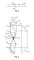
- Fig. 4 shows a cross section of the data carrier of Fig. 1.
- the centre of the circular data carrier is depicted by the vertical line 60 through the center hole of the data carrier.
- the surface of the data carrier is essentially flat except for the annular hologram area 10, which sticks out from the surface of the data carrier.
- a readout apparatus for the data carrier 1 needs to be capable of focusing a readout light beam onto the surface of the data carrier.
- the hologram area 10 may likewise be integrated within the data carrier, as indicated by the dashed lines.
- Fig. 5 shows a device for generating a security mark on an optical data carrier.
- the optical data carrier 1 and the hologram area of Fig. 1 are designated by reference signs 1 and 10, respectively.
- a laser source 3 is shown in Fig. 5.
- the laser light emitted from the source 3 is collimated by a collimator lens 4. It is directed through a beam splitter 5, which outputs a first collimated laser beam 7 and a second collimated laser beam 6.
- the first laser beam 7 is directed along a first direction and focused onto the hologram area 10 by a first objective lens 8a.
- the second laser beam 6 is directed along a second direction through the second objective lens 8b onto the hologram area 10.
- Two fixed mirrors 11a, 11b and an adjustable mirror 12 are provided in Fig.
- the second laser beam 6 reaches the hologram area 10 from the opposite side than the first laser beam 7.
- both laser beams 6, 7 impinge on the hologram area 10 from the same side, e.g. from the side of the first laser beam 7.
- Said second direction of the second laser beam 6 is slightly tilted by a tilt angle with respect to the direction of the first laser beam 7. The tilt angle can be adjusted by the adjustable mirror 12, which directs the second laser beam 6 through the second objective lens 8b.
- the first and second laser beams 7 and 6 overlap within the hologram area 10 and create an interference pattern within the material.
- the interference pattern depends on the tilt angle, which is preferably fixed between -5° and 5°.
- the maximum angle depends on the type of optical data carrier and the objective lens used for playback. For example, for a Compact Disk a larger angle is needed than for a BluRay disk.
- the hologram area 10 in Fig. 5 is shown in a cross sectional view similar to the depiction in Fig. 4.
- the interference pattern introduced into the holographic material corresponds to one of the holograms 40 in Fig. 3.
- the second laser beam 6 in Fig. 5 is tilted in a direction perpendicular to the lengthwise direction of one of the stripes 30 in Figs. 2 and 3.
- the tilt angle lies in a plane perpendicular to the radial direction of the circular data carrier 1 in Fig. 1. Therefore, the optical properties of the resulting interference pattern do not change in the lengthwise direction of the stripes 30. However, the shift selectivity in a direction perpendicular to the length of the stripes 30 is high.
- An information bit of 0 or 1 is encoded by the positive or negative shift angle of the second laser beam 6 and the resulting interference pattern.
- Several overlapping holograms 40 are written for each data bit.
- the radius of the two focused laser beams 6 and 7 within the hologram area 10 has the same magnitude.
- Fig. 6 shows readout device for reading out the security mark stored on the data carrier of Fig. 1.
- Identical reference signs in Fig. 5 and 6 denote similar objects in both Figures.
- the laser source 3, the collimator lens 4, and the collimated laser beam 7 are arranged essentially in the same way as in Fig. 5.
- the laser beam 7 is directed through a beam splitter 13 and an objective lens 8 onto the hologram area 10.
- a security mark is stored in the hologram area 10 in Fig. 6.
- a reflective layer 18 and a substrate 19 are positioned below the hologram area 10.
- the readout device comprises a detector 15 for detecting the light reflected from the reflective layer 18.
- a focus lens 14 focuses the reflected light onto the detector 15.
- a comparator 20 analyzes the intensity distribution detected by the detector 15 for determining the tilt angle of a reconstructed signal beam 17.
- the first beam 7 is a beam, which passes through the interference pattern of the hologram without being diffracted. The reflection reaches the beam splitter 13 and is reflected from there to the detector 15. Part of the laser beam 7 is diffracted by the interference pattern stored in the hologram area 10 and generates the signal beam 17.
- This signal beam 17 is directed through the objective lens 8, the beam splitter 13 and the focus lens 14 onto the detector 15. As the signal beam 17 is slightly tilted, the focus of the signal beam 17 is situated off the centre on the detector 15.
- phase-conjugated signal beam 16 propagates first to the reflective layer 18, before it is focused onto the detector 15. Due to the reflection losses at the mirror layer 18 the phase-conjugated signal beam 16 is much weaker than the direct signal beam 17. As a consequence, the light pattern on the detector surface of the detector 15 is formed by the superimposition of three distinct beams 7, 16 and 17.
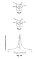
- Fig. 7 shows the detection area of the detector 15 of Fig. 6.
- the detection area is formed of four distinct detector elements a, b, c and d, which are positioned in a chequered arrangement.
- Figs. 8 and 9 each show the detection area of Fig. 7.
- the detection area is illuminated by the different light beams 7, 16, 17 coming from the hologram area 10 of Fig. 6.
- Light beams 7, 16 and 17 correspond to the circular spots 7a/b, 16a/b and 17a/b, respectively.
- the undiffracted laser beam 7 forms a circular spot 7a/b in the centre of the detection area in both Figs. 8 and 9.
- the position of the spot resulting from the signal beam 17 is shifted to the right in Fig. 8 (spot 17a) and to the left in Fig. 9 (17b).
- the spot resulting from the phase-conjugated signal beam 16 is shifted to the left in Fig. 8 (spot 16a) and to the right in Fig.
- spot 16b spot 16b.
- the spots 7a and 7b of the undiffracted laser beam 7 have the greatest intensity of all the spots. Therefore the intensity of the spots 17a/17b is larger than the intensity of the spots 16a/b. Therefore, the light intensity distribution in Fig. 8 is shifted to the right, whereas the light intensity distribution in Fig. 9 is shifted to the left.
- the position of the spots 16a/b and 17a/b depends on the tilt angle used during the production of the interference pattern in the hologram area 10. Therefore, the information bit corresponding to the shift angle may be determined by finding out whether the intensity distribution is shifted to the left or right on the detection are.
- the signal S is similar to a tangential push-pull signal. If a position sensitive photo detector is used, it is also possible to encode more than one information bit. In addition to the sign of the tilt angle also the value of the tilt angle can be detected.
- the variables ⁇ x, ⁇ y represent the shift of the incident light beam 7 in Fig. 6 with respect to the recorded interference pattern in the hologram area.
- ⁇ y represents a shift of the incident light beam in a radial direction of the disk in Fig. 2.
- ⁇ x represents a shift in a scanning direction of the incident laser beam, which is perpendicular to the radial direction.
- L x and L y designate the lateral extension of the hologram.
- L is the thickness of the hologram.
- n is the refractive index of the holographic material.
- R 1 is the radius of the focused incident laser beam 7 in Fig. 5.
- Fig. 10 shows the total normalized diffracted signal I ( ⁇ x, ⁇ y ) in relation to the shift ⁇ x. Since the signal is normalized, the maximum signal intensity is set equal to one.
- the curve in Fig. 10 has been calculated for the following values, which are realistic for a disk using a blue laser beam.
- the total signal intensity decreases continually in the positive and negative direction ⁇ x .
- the total signal intensity has reached less than 1/5 of the peak.
- the main advantages of the security mark recorded according to the preferred embodiment are the following.
- the additional security mark is compatible with existing disk families such as Compact Disk (CD), Digital Versatile Disk (DVD) and BluRay disk (BD).
- the readout device of Fig. 6 corresponds largely to existing readout devices.
- a comparator 20 for determining the light intensity distribution on the detector area has to be added to existing readout devices in order to detect the stored information bit.
- the standard photodetector for data readout can be used for reading the security marks.
- the costs for adapting the existing readout devices are low.
- the production of the respective data carriers having the security mark is also very low.
Landscapes
- Engineering & Computer Science (AREA)
- Computer Security & Cryptography (AREA)
- Signal Processing (AREA)
- Optical Recording Or Reproduction (AREA)
- Holo Graphy (AREA)
Abstract
Generating the security mark (30) through interference of the first and second light beam, wherein an information bit is encoded by the sign and/or the value of the tilt angle.
Description
- The present invention is directed to a method for generating a security mark on an optical data carrier, a data carrier, comprising a security mark, a method for reading out the security mark stored on the data carrier and a device for reading out the security mark stored on the data carrier.
- The term security mark is to denote a bit sequence, which is for example used for providing an authentication key or decrypting key on a data carrier. Authentication and encryption are commonly used on data carriers in order to prevent unauthorized copying of information, which is stored on the data carrier and protected by copyright law. The authentication key is used for establishing or confirming that the data carrier contains a legally sold copy and has not been copied in breach of copyright protection. The readout of data from the data carrier is prevented if the authentication key is inexistent or incorrect. Alternatively, the data may be encrypted, such that a decrypting key is necessary for obtaining the stored information from the read out bit sequences.
- The security mark may only protect unauthorized copying and reproduction of data stored on a data carrier if the security mark may not be copied using standard disk drives. Conventional disk drives such as Compact Disks (CD), Digital Versatile Disks (DVD) or BluRay Disks (BD) use a focused laser beam for storing data on the disk. Thereby, a series of microscopic indentations ("pits", with the gaps between them referred to as "lands") are formed in the recording area of the disk. The laser beam is directed onto a reflective surface of the disk to read the pattern of pits and lands. The pattern of changing intensity of the reflected beam is converted into binary data.
- The international patent application
WO 2005/048256 discloses using a hologram, from which a key or authentication mark can be derived. A hologram is an advanced form of photographic recording that allows an image to be recorded in three dimensions. The technique of holography can also be used to optically store, retrieve, and process information. To produce a recording of the phase of the light wave at each point in an image, holography uses a reference beam which is combined with the light from the scene or object (the object beam). Optical interference between the reference beam and the object beam, due to the superposition of the light waves, produces a series of intensity fringes that can be recorded on standard photographic film. These fringes form a type of diffraction pattern on the film, which is called the hologram or the interference pattern. Therefore two coherent light beams, an object beam and a reference beam, are necessary for recording a hologram. A conventional disk drive does not have the means for recording a hologram. The technical equipment and know how for copying a holographic recording is complex and expensive. Furthermore, the analysis and reproduction of the diffraction pattern on the film is a formidable task. Therefore, unauthorized copying and reproduction of the security mark is impeded. - However, the security mark stored as a holographic recording may not be readout using a standard disk drive. According to the international patent application
WO 2005/048256 a unique spatial modulation filter must be applied at the level of the analysis of the security mark. Therefore, the holographic security mark according to the state of the art necessitates a difficult and expensive modification of the disk drive in order to be readable. The data carriers having these holographic security marks are not compatible with existing disk drives. - Therefore, it is an object of the present invention to provide an improved data carrier, comprising a security mark, which may not be copied using standard disk drive. The security mark should be readable using disk drives, which do not require an ample and expensive modification in relation to conventional disk drives. Furthermore, it is object to provide a method for generating the improved optical data carrier having the security mark, a method for reading out the security mark and a device for reading out the security mark.
- The object is solved by the method for generating a security mark on an optical data carrier and the respective optical data carrier according to the appended claims.
- According to the present invention, a method for generating a security mark on an optical data carrier is provided. The method comprises the steps of directing a first and second light beam onto a hologram area of the optical data carrier. The first and second light beams are coherent light beams. Consequently, the first and second light beams form an interference pattern, if they are superimposed on each other. The first light beam is directed onto the hologram area along a first direction. Preferably, the first direction is perpendicular relative to the surface of the optical data carrier. Simultaneously, the second light beam is directed onto the hologram area along a second direction. The second direction is tilted by a predefined tilt angle with respect to the first direction. The first light beam and the second light beam are either directed to the same side or to opposite sides of the optical data carrier.
- The first and second light beams form an interference pattern, which is recorded in the hologram area. A conventional disk drive may not record an interference pattern, since it does not have the means for generating two coherent light beams, which may be simultaneously directed to a hologram area. Therefore, the security mark on an optical data carrier generated in the aforementioned way is safe from unauthorized copying. Furthermore, the reproduction of the security mark may be accomplished without expensively modifying existing disk drives. The normal photodetector provided for readout of the data stored on the optical data carrier is preferably used for reading the data stored in the hologram area. The additional security mark is preferably stored in a hologram area, which is an integral part of the optical data carrier. However, the security marks may likewise be recorded in a separate holographic data carrier, which is affixed to the optical data carrier. An example of such a holographic data carrier is a self-adhesive polymer tape. This material is available at very low cost under the trademark name Tesa Scribos. Of course, other holographic materials may also be used. The holograms stored in the hologram area may represent a visible image of a brand or logo, so that a consumer can identify the product.
- Preferably, the tilt angle us is greater than or equal to -5° and smaller than or equal to 5°, i.e. -5°≤us≤5°. Restricting the size of the tilt angle in this way has the advantage that a reproduction of the recording in the hologram area may be accomplished using the normal photodetector provided for readout of the data stored on the optical data carrier. The local shift between the reconstructed images on the detector area is determined by the change in the tilt angle.
- According to a preferred embodiment of the present invention, the first and/or second light beams are focused onto the hologram area. Thereby, the recording area may be appropriately restricted. A greater amount of data may be stored in the security mark. A focused readout beam needs to be used in order to reproduce the stored security data. Since conventional disk drives provide focused laser beams, no further modification of the disk drive would be needed in terms of the laser beam. However, alternatively a defocused first or second light beam could be used. In this case, the disk drive must be modified in order to generate a corresponding defocused readout beam. The focusing system of the readout device preferably compares the focus position of the data layer with the one necessary to read out the hologram. This is advantageously used as an additional security feature.
- Preferably, a single laser source is used for generating the first and second light beams. A beam splitter is used for splitting laser light emitted from the laser source into the first and second light beams. Due to the long coherence length of laser light, the first and second light beams interfere when they reach the hologram area.
- A plurality of identical security marks are preferably generated in the hologram area by shifting said first and second light beam in a third direction, e.g. perpendicular to the first and second direction. Consequently, the plurality of identical marks forms a line of overlapping identical security marks in the hologram area. The tilt angle is preferably perpendicular to the line. In this case, a reconstructed light beam does not change, if the readout light beam is shifted along the line of identical security marks. The readout of the security mark is insensitive to a shift of the readout light beam in the direction of the line of identical security marks. No additional guiding track for positioning of the readout light beam needs to be provided. Thereby, the additional cost for producing the security mark may be lessened. If the tilt angle is parallel or diagonal to the line, a guiding track needs to be provided.
- Favorably, the hologram area is arranged on the optical data carrier in such a way that the line of overlapping identical security marks is perpendicular to a scanning direction for reading the information stored in the hologram area. Conventionally, the scanning direction is perpendicular to a radial direction of a circular disk. The security marks may be positioned between the centre of the circular disk and a data storage area. In this configuration, the lines are aligned along a radius of the circular disk.
- The present invention is directed to an optical data carrier, which comprises a security mark. The security mark is preferably generated using the method for generating a security mark on an optical data carrier according to the present invention. However, the optical data carrier of the present invention may also be generated using other methods. The same security marks may be produced using a master hologram and the known process of contact replication, as described by Inphase et al in Optics Letter 2006, p. 1050.
- The present invention also relates to a method for reading out the security mark stored on the optical data carrier according to the present invention. The inventive method comprises the step of directing a readout light beam onto the security mark along the first direction. A reconstructed light beam along the second direction is generated by the security mark, which is directed onto a detection area. An information bit corresponding to said tilt angle is detected by determining an intensity distribution of the reconstructed light beam on the detection area. The recorded security mark forms different diffraction patterns for the readout light beam depending on the tilt angle used for recording. Therefore, the reconstructed light beam, which is generated by the diffraction of the readout light beam by the security mark, forms different patterns on the detection area depending on the tilt angle. The pattern of the reconstructed light beam is detected in order to determine the information bit stored in the security mark. Information is preferably encoded in the sign of the tilt angle. However, if a position sensitive photo detector is used, it is also possible to encode information in the value of the tilt angle.
- Preferably, for detecting the intensity distribution of the reconstructed light beam the detection area is divided into a plurality of adjacent photo detector areas. The detected light intensity of the adjacent photo detector areas is compared with each other. If, for example, the detection area is split in only two adjacent photo detector areas, then it is possible to determine which photo detector area has received more light by comparing the light intensity detected by the respective photo detector areas.
- A readout device for reading out the security mark stored on the data carrier according to the present invention comprises a light source adapted to direct a readout light beam onto the security mark along the first and/or second direction. The readout light beam interacts with the security mark and generates a reconstructed light beam. A collimator is adapted to direct the reconstructed light beam onto a photo detector. The photo detector is adapted to detect an information bit corresponding to the tilt angle by analyzing the intensity distribution of the reconstructed light beam on the photo detector.
- Preferably, a readout device for reading out the security mark stored on the data carrier according to the present invention comprises a detector having a plurality of photo detectors. The detection area is divided into a plurality of adjacent photo detector areas. The readout device comprises a comparator adapted to compare the detected light intensity of the adjacent photo detector areas.
- A preferred embodiment of the present invention is described hereinafter with reference to the accompanied drawings. The preferred embodiments may not be construed as limiting the scope of the present invention, which is defined by the appended claims. They are only meant to exemplify the present invention.
- Fig. 1
- shows a top view of a schematic depiction of a data carrier having a region with security marks according to the preferred embodiment of the present invention,
- Fig. 2
- shows a top view of a close up of the region of security marks of the data carrier of Fig. 1,
- Fig. 3
- shows a top view of a close up of a line of security marks of Fig. 2,
- Fig. 4
- shows a lateral view of the data carrier of Fig. 1,
- Fig. 5
- shows a device for generating a security mark on an optical data carrier,
- Fig. 6
- shows a readout device for reading out the security mark stored on the data carrier of Fig. 1,
- Fig. 7
- shows a detection area of the readout device of Fig. 6,
- Fig. 8
- shows the detection area of Fig. 7, wherein the detection area is illuminated by first readout light beams,
- Fig. 9
- shows the detection area of Fig. 7, wherein the detection area is illuminated by second readout light beams, and
- Fig. 10
- shows a graph of normalized total signal intensity on the detection area of Fig. 7 versus a shift of the incident readout light beam.
- Fig. 1 shows a top view of a schematic depiction of a data carrier having a region with security marks according to the preferred embodiment of the present invention. The data carrier has the shape of a disk 1. A
hologram area 10 is provided on the disk 1 in a region close to the centre of the disk 1. Thehologram area 10 is either an integral part of the disk 1, or it is an independent holographic storage medium fixed to the disk 1. Thehologram area 10 forms an annulus, i.e. a ringshaped geometric figure. The disk 1 comprises aregion 20 for data storage. Thedata storage region 20 also has an annular shape, which encloses thehologram area 10. - Fig. 2 shows a top view of a close up of the
hologram area 10 of the data carrier of Fig. 1. Thehologram area 10 is used for storing security marks on the data carrier. The security marks are formed as a plurality ofstripes 30, which are arranged essentially in parallel to each other. More precisely, each stripe is collinear with a straight line projecting from the centre of the circular data carrier in Fig. 1 to the circumference of the circular data carrier. Adjacent stripes are approximately parallel to each other. Though thestripes 30 are drawn asseparate stripes 30, they can likewise overlap. - In Fig. 3 four
stripes 30 of thehologram area 10 Fig. 2 are depicted. Thestripes 30 consist of a plurality of approximatelycircular holograms 40, which are superimposed upon each other. As a consequence, the reconstructed object beam does not change when the readout beam is shifted along the stripe. The readout of the security mark is insensitive to a shift of the readout light beam in the direction of the stripe ofidentical holograms 40. Therefore, no additional guiding track for positioning of the readout light beam needs to be provided. - Each
stripe 30 in Fig. 3 represents a single bit of information. The information bit is read out by illuminating thestripe 30 with a readout light beam. Through diffraction by the holograms 40 a reconstructed object beam is generated. The pattern of the reconstructed object beam remains virtually unchanged if the readout light beam is shifted in the lengthwise direction of eachstripe 30. Therefore, the radial position of the readout light beam with respect to thestripes 30 in thehologram area 10 is uncritical. Preferably, the light beam for readout is focused in the plane of thehologram area 10. The focus position can be controlled via the conventional focus servo providing that the disk is sufficiently reflective in the region of thehologram area 10. - Fig. 4 shows a cross section of the data carrier of Fig. 1. The centre of the circular data carrier is depicted by the
vertical line 60 through the center hole of the data carrier. The surface of the data carrier is essentially flat except for theannular hologram area 10, which sticks out from the surface of the data carrier. In this case a readout apparatus for the data carrier 1 needs to be capable of focusing a readout light beam onto the surface of the data carrier. Of course, thehologram area 10 may likewise be integrated within the data carrier, as indicated by the dashed lines. - Fig. 5 shows a device for generating a security mark on an optical data carrier. The optical data carrier 1 and the hologram area of Fig. 1 are designated by
reference signs 1 and 10, respectively. Alaser source 3 is shown in Fig. 5. The laser light emitted from thesource 3 is collimated by acollimator lens 4. It is directed through abeam splitter 5, which outputs a first collimatedlaser beam 7 and a second collimatedlaser beam 6. Thefirst laser beam 7 is directed along a first direction and focused onto thehologram area 10 by a firstobjective lens 8a. Thesecond laser beam 6 is directed along a second direction through the secondobjective lens 8b onto thehologram area 10. Twofixed mirrors adjustable mirror 12 are provided in Fig. 5 in order to redirect thesecond laser beam 6. Thesecond laser beam 6 reaches thehologram area 10 from the opposite side than thefirst laser beam 7. Of course, it is likewise possible that bothlaser beams hologram area 10 from the same side, e.g. from the side of thefirst laser beam 7. Said second direction of thesecond laser beam 6 is slightly tilted by a tilt angle with respect to the direction of thefirst laser beam 7. The tilt angle can be adjusted by theadjustable mirror 12, which directs thesecond laser beam 6 through the secondobjective lens 8b. - The first and
second laser beams hologram area 10 and create an interference pattern within the material. The interference pattern depends on the tilt angle, which is preferably fixed between -5° and 5°. The maximum angle depends on the type of optical data carrier and the objective lens used for playback. For example, for a Compact Disk a larger angle is needed than for a BluRay disk. Thehologram area 10 in Fig. 5 is shown in a cross sectional view similar to the depiction in Fig. 4. The interference pattern introduced into the holographic material corresponds to one of theholograms 40 in Fig. 3. Thesecond laser beam 6 in Fig. 5 is tilted in a direction perpendicular to the lengthwise direction of one of thestripes 30 in Figs. 2 and 3. The tilt angle lies in a plane perpendicular to the radial direction of the circular data carrier 1 in Fig. 1. Therefore, the optical properties of the resulting interference pattern do not change in the lengthwise direction of thestripes 30. However, the shift selectivity in a direction perpendicular to the length of thestripes 30 is high. An information bit of 0 or 1 is encoded by the positive or negative shift angle of thesecond laser beam 6 and the resulting interference pattern. Several overlappingholograms 40 are written for each data bit. Furthermore, the radius of the twofocused laser beams hologram area 10 has the same magnitude. - Fig. 6 shows readout device for reading out the security mark stored on the data carrier of Fig. 1. Identical reference signs in Fig. 5 and 6 denote similar objects in both Figures. In particular the
laser source 3, thecollimator lens 4, and the collimatedlaser beam 7 are arranged essentially in the same way as in Fig. 5. Thelaser beam 7 is directed through abeam splitter 13 and an objective lens 8 onto thehologram area 10. A security mark is stored in thehologram area 10 in Fig. 6. Areflective layer 18 and asubstrate 19 are positioned below thehologram area 10. Furthermore, the readout device comprises adetector 15 for detecting the light reflected from thereflective layer 18. Afocus lens 14 focuses the reflected light onto thedetector 15. Acomparator 20 analyzes the intensity distribution detected by thedetector 15 for determining the tilt angle of areconstructed signal beam 17. - Three
different laser beams detector lens 14. Thefirst beam 7 is a beam, which passes through the interference pattern of the hologram without being diffracted. The reflection reaches thebeam splitter 13 and is reflected from there to thedetector 15. Part of thelaser beam 7 is diffracted by the interference pattern stored in thehologram area 10 and generates thesignal beam 17. Thissignal beam 17 is directed through the objective lens 8, thebeam splitter 13 and thefocus lens 14 onto thedetector 15. As thesignal beam 17 is slightly tilted, the focus of thesignal beam 17 is situated off the centre on thedetector 15. In addition, there is asecond signal beam 16, which is created by the reflected, phase-conjugated readout beam 7. This phase-conjugated signal beam 16 propagates first to thereflective layer 18, before it is focused onto thedetector 15. Due to the reflection losses at themirror layer 18 the phase-conjugated signal beam 16 is much weaker than thedirect signal beam 17. As a consequence, the light pattern on the detector surface of thedetector 15 is formed by the superimposition of threedistinct beams - Fig. 7 shows the detection area of the
detector 15 of Fig. 6. The detection area is formed of four distinct detector elements a, b, c and d, which are positioned in a chequered arrangement. - Figs. 8 and 9 each show the detection area of Fig. 7. The detection area is illuminated by the
different light beams hologram area 10 of Fig. 6.Light beams circular spots 7a/b, 16a/b and 17a/b, respectively. Theundiffracted laser beam 7 forms acircular spot 7a/b in the centre of the detection area in both Figs. 8 and 9. The position of the spot resulting from thesignal beam 17 is shifted to the right in Fig. 8 (spot 17a) and to the left in Fig. 9 (17b). The spot resulting from the phase-conjugated signal beam 16 is shifted to the left in Fig. 8 (spot 16a) and to the right in Fig. 9 (spot 16b). Thespots undiffracted laser beam 7 have the greatest intensity of all the spots. Therefore the intensity of thespots 17a/17b is larger than the intensity of thespots 16a/b. Therefore, the light intensity distribution in Fig. 8 is shifted to the right, whereas the light intensity distribution in Fig. 9 is shifted to the left. The position of thespots 16a/b and 17a/b depends on the tilt angle used during the production of the interference pattern in thehologram area 10. Therefore, the information bit corresponding to the shift angle may be determined by finding out whether the intensity distribution is shifted to the left or right on the detection are. Let Ia, Ib, Ic and Id represent the total light intensity in the respective detector areas a, b, c and d. Then, the sign of S=(Ia+Ic-Ib-Id)/(Ia+Ib+Ic+Id) is representative of the stored information bit. The signal S is similar to a tangential push-pull signal. If a position sensitive photo detector is used, it is also possible to encode more than one information bit. In addition to the sign of the tilt angle also the value of the tilt angle can be detected. - The total normalized diffracted signal as a function of the readout beam shift is given by the following equation:

- In this equation, the variables δx, δy represent the shift of the
incident light beam 7 in Fig. 6 with respect to the recorded interference pattern in the hologram area. δy represents a shift of the incident light beam in a radial direction of the disk in Fig. 2. δx represents a shift in a scanning direction of the incident laser beam, which is perpendicular to the radial direction. The above formula applies for a single, non overlapping hologram recorded using the setup of Fig. 5. Lx and Ly designate the lateral extension of the hologram. L is the thickness of the hologram. n is the refractive index of the holographic material. R1 is the radius of the focusedincident laser beam 7 in Fig. 5. R2 is the radius of thefocused laser beam 6 in Fig. 5; us represents the tilt angle between theincident laser beams - Fig. 10 shows the total normalized diffracted signal I(δx,δy) in relation to the shift δx. Since the signal is normalized, the maximum signal intensity is set equal to one. The curve in Fig. 10 has been calculated for the following values, which are realistic for a disk using a blue laser beam.


- The total normalized diffracted signal represents a distribution, which has a singular peak at δx=0. The total signal intensity decreases continually in the positive and negative direction δx. At around ±5µm the total signal intensity has reached less than 1/5 of the peak. The shift selectivity is roughly about 10 µm. Therefore, adjacent interference patterns are distinguishable if they are recorded at a distance of 10µm. If the security markers are recorded in a distance r=20mm from the centre of the disk in Fig. 2, then the circumference of the security marker region is equal to 2nr and the total number of bits is equal to 2πr/10µm=12500 raw data bits.
- The main advantages of the security mark recorded according to the preferred embodiment are the following. The additional security mark is compatible with existing disk families such as Compact Disk (CD), Digital Versatile Disk (DVD) and BluRay disk (BD). The readout device of Fig. 6 corresponds largely to existing readout devices. A
comparator 20 for determining the light intensity distribution on the detector area has to be added to existing readout devices in order to detect the stored information bit. However, the standard photodetector for data readout can be used for reading the security marks. The costs for adapting the existing readout devices are low. The production of the respective data carriers having the security mark is also very low. - The above preferred embodiment is not intended to restrict the scope of protection to be conferred to the present application. The preferred embodiment is only meant to exemplify a convenient way for implementing the invention. The invention is defined by the appended claims.
Claims (15)
- Method for generating a security mark (30) on an optical data carrier (1), comprising the steps of:directing a first and a second light beam (7, 6) onto a hologram area (10) of the optical data carrier (1), wherein the first and second light beams (7, 6) are coherent light beams, the first light beam (7) being directed onto the hologram area (10) along a first direction, and the second light beam (6) being directed onto the hologram area (10) along a second direction, andgenerating the security mark (30) through interference of the first and the second light beam (7, 6),characterized by the step of
tilting the second direction by a predefined tilt angle with respect to the first direction, wherein an information bit is encoded by the sign and/or the value of the tilt angle. - Method according to claim 1, wherein the tilt angle is greater than or equal to -5° and smaller than or equal to 5°.
- Method according to claim 1 or 2, wherein the first and/or second light beams (7, 6) are focused on the hologram area (10).
- Method according to one of the claims 1 to 3, having the steps of using a single light source (3) for generating the first and second light beams (7, 6), and using a beam splitter (5) for splitting laser light emitted from the light source (3) into the first and second light beams (7, 6).
- Method according to one of the claims 1 to 4, having the step of generating a plurality of identical security marks (30) in the hologram area (10) by shifting said first and second light beams (7, 6) in a third direction relative to the first and second direction, such that the plurality of identical security marks (30) form a line of overlapping identical security marks in the hologram area (10).
- Method according to one of the claims 1 to 5, having the step of arranging the hologram area (10) on the optical data carrier (1) in such a way that the line of overlapping identical security marks (30) is perpendicular to a scanning direction for reading the information stored in the hologram area (10).
- Optical data carrier (1), comprising a security mark (30) in a hologram area (10), wherein said security mark (30) is adapted to generate a reconstructed light beam (17a, 17b) along a second direction when illuminated by a readout light beam (7) along a first direction, the second direction being tilted relative to the first direction, wherein an information bit is encoded by the sign and/or the value of the tilt angle.
- Device for generating a security mark (30) on an optical data carrier (1), comprising:directing means (8a, 8b, 11) for directing a first and a second light beam (7, 6) onto a hologram area (10) of the optical data carrier (1), wherein the first and second light beams (7, 6) are coherent light beams, the directing means (8a, 8b, 11) being adapted to direct the first light beam (7) onto the hologram area (10) along a first direction, and the second light beam (6) onto the hologram area (10) along a second direction, such that the security mark (30) is generated through interference of the first and the second light beam (7, 6),
wherein the device further comprisestilting means (12) for tilting the second direction by a predefined tilt angle with respect to the first direction, wherein an information bit is encoded by the sign and/or the value of the tilt angle. - Method for reading out a security mark (30) stored on an optical data carrier (1), comprising the steps of
directing a readout light beam (7) onto the security mark (30) along a first direction,
directing a reconstructed light beam (17a, 17b) along a second direction onto a detection area (a, b, c, d), the second direction depending on an information bit recorded in the security mark (30), and
detecting the information bit from a tilt angle between the first direction and the second direction by analyzing an intensity distribution of the reconstructed light beam (17a, 17b) on the detection area (a, b, c, d). - Method according to claim 9, wherein for analyzing the intensity distribution of the reconstructed light beam (17a, 17b) the detection area (a, b, c, d) is divided into a plurality of adjacent photo detector areas, and comparing the detected light intensity of the adjacent photo detector areas.
- Method according to claim 9 or 10, further having the step of comparing the focus position of a data layer with the focus position necessary to read out the security mark (30).
- Readout device for reading out a security mark (30) stored on an optical data carrier (1), comprising:a light source (3) adapted to direct a readout light beam (7) onto the security mark (30) along a first direction,a collimator (8) adapted to direct a reconstructed light beam (17a, 17b) along a second direction onto a photo detection area (a, b, c, d) of a detector (15), the second direction depending on an information bit recorded in the security mark (30), anda comparator (20) adapted to detect an information bit from a tilt angle between the first direction and the second direction by analyzing an intensity distribution of the reconstructed light beam (17a, 17b) on the detection area (a, b, c, d).
- Readout device according to claim 12, wherein said detector (15) comprises a plurality of adjacent photo detector areas (a, b, c, d), and wherein said readout device comprises a comparator adapted to compare the detected light intensity of the adjacent photo detector areas (a, b, c, d).
- Readout device according to claim 12 or 13, further having a comparator for comparing the focus position of a data layer with the focus position necessary to read out the security mark (30).
- Holographic storage medium adapted to be fixed to an optical data carrier (1), with a security mark (30), wherein said security mark (30) is adapted to generate a reconstructed light beam (17a, 17b) along a second direction when illuminated by a readout light beam (7) along a first direction, the second direction being tilted relative to the first direction, wherein an information bit is encoded by the sign and/or the value of the tilt angle.
Priority Applications (1)
| Application Number | Priority Date | Filing Date | Title |
|---|---|---|---|
| EP20070301468 EP1918915B1 (en) | 2006-10-31 | 2007-10-16 | Method for producing a security mark on an optical data carrier |
Applications Claiming Priority (2)
| Application Number | Priority Date | Filing Date | Title |
|---|---|---|---|
| EP06123229A EP1918913A1 (en) | 2006-10-31 | 2006-10-31 | Method for producing a security mark on an optical data carrier |
| EP20070301468 EP1918915B1 (en) | 2006-10-31 | 2007-10-16 | Method for producing a security mark on an optical data carrier |
Publications (3)
| Publication Number | Publication Date |
|---|---|
| EP1918915A2 true EP1918915A2 (en) | 2008-05-07 |
| EP1918915A3 EP1918915A3 (en) | 2012-10-03 |
| EP1918915B1 EP1918915B1 (en) | 2014-03-05 |
Family
ID=39263266
Family Applications (1)
| Application Number | Title | Priority Date | Filing Date |
|---|---|---|---|
| EP20070301468 Expired - Fee Related EP1918915B1 (en) | 2006-10-31 | 2007-10-16 | Method for producing a security mark on an optical data carrier |
Country Status (1)
| Country | Link |
|---|---|
| EP (1) | EP1918915B1 (en) |
Citations (6)
| Publication number | Priority date | Publication date | Assignee | Title |
|---|---|---|---|---|
| US4677285A (en) * | 1982-05-18 | 1987-06-30 | Dai Nippon Insatsu Kabushiki Kaisha | Identification article with pattern-form fresnel hologram, fabrication thereof, and verification thereof |
| EP0374256B1 (en) * | 1988-04-12 | 1998-02-25 | Dai Nippon Insatsu Kabushiki Kaisha | Optical recording medium and method of manufacturing same |
| WO1998012703A2 (en) * | 1996-09-05 | 1998-03-26 | Wea Manufacturing, Inc. | Holographic security system for optical discs |
| US20030233100A1 (en) * | 2002-06-12 | 2003-12-18 | Michael Santarella | Modular hip inserter/positioner |
| WO2004095447A1 (en) * | 2003-04-16 | 2004-11-04 | Holographic Image Studio Ltd | An optical data carrier |
| EP1626407A2 (en) * | 1998-08-10 | 2006-02-15 | OVD Kinegram AG | Diffractive security device on compact discs |
-
2007
- 2007-10-16 EP EP20070301468 patent/EP1918915B1/en not_active Expired - Fee Related
Patent Citations (6)
| Publication number | Priority date | Publication date | Assignee | Title |
|---|---|---|---|---|
| US4677285A (en) * | 1982-05-18 | 1987-06-30 | Dai Nippon Insatsu Kabushiki Kaisha | Identification article with pattern-form fresnel hologram, fabrication thereof, and verification thereof |
| EP0374256B1 (en) * | 1988-04-12 | 1998-02-25 | Dai Nippon Insatsu Kabushiki Kaisha | Optical recording medium and method of manufacturing same |
| WO1998012703A2 (en) * | 1996-09-05 | 1998-03-26 | Wea Manufacturing, Inc. | Holographic security system for optical discs |
| EP1626407A2 (en) * | 1998-08-10 | 2006-02-15 | OVD Kinegram AG | Diffractive security device on compact discs |
| US20030233100A1 (en) * | 2002-06-12 | 2003-12-18 | Michael Santarella | Modular hip inserter/positioner |
| WO2004095447A1 (en) * | 2003-04-16 | 2004-11-04 | Holographic Image Studio Ltd | An optical data carrier |
Also Published As
| Publication number | Publication date |
|---|---|
| EP1918915B1 (en) | 2014-03-05 |
| EP1918915A3 (en) | 2012-10-03 |
Similar Documents
| Publication | Publication Date | Title |
|---|---|---|
| RU2124764C1 (en) | Disk-shaped optical storage medium and method for its manufacturing | |
| EP0980070B1 (en) | Diffractive security device on compact discs | |
| EP1460622B1 (en) | Method for recording and reproducing holographic data and holographic recording medium | |
| US20020136143A1 (en) | Tracking techniques for holographic data storage media | |
| WO2006031494A2 (en) | Copy protected optical storage discs | |
| US7453791B2 (en) | Optical recording medium having a plurality of guide tracks transfer regions | |
| US8953235B2 (en) | Method for producing a security mark on an optical data carrier | |
| EP0871954B1 (en) | Holographic security system for optical discs | |
| EP1918915B1 (en) | Method for producing a security mark on an optical data carrier | |
| US7158274B2 (en) | Pick-up apparatus for digital storage medium | |
| EP1658608B1 (en) | Optical record carrier | |
| JP2753321B2 (en) | Optical information reproducing method and apparatus | |
| EP1912209A1 (en) | Optical recording medium, recording method of information on optical recording medium and reproducing method thereof | |
| JP3904050B2 (en) | Optical search method and optical search device | |
| JP2017162523A (en) | Recording medium and hologram recording/reproducing apparatus | |
| JP2007178592A (en) | Optical information recording medium, method for manufacturing optical information recording medium, method for reproducing optical information recording medium and reproducing device for optical information recording medium | |
| JP4525308B2 (en) | Hologram recording apparatus, hologram reproducing apparatus, hologram recording method, and hologram reproducing method | |
| US20080186839A1 (en) | Optical Information Carrier | |
| JP2006171416A (en) | Medium for recording hologram and apparatus for recording and reproducing hologram | |
| AU718735C (en) | Holographic security system for optical discs | |
| JP2005235312A (en) | Recording and reproducing apparatus | |
| EP1914741A2 (en) | Optical pickup apparatus and optical reproducing method | |
| JP2000132870A (en) | Optical information recording medium, its manufacture and its reproducing device | |
| JP2002298395A (en) | Method and device for detecting tracking error | |
| JP2005285251A (en) | Optical recording/reproducing system |
Legal Events
| Date | Code | Title | Description |
|---|---|---|---|
| PUAI | Public reference made under article 153(3) epc to a published international application that has entered the european phase |
Free format text: ORIGINAL CODE: 0009012 |
|
| AK | Designated contracting states |
Kind code of ref document: A2 Designated state(s): AT BE BG CH CY CZ DE DK EE ES FI FR GB GR HU IE IS IT LI LT LU LV MC MT NL PL PT RO SE SI SK TR |
|
| AX | Request for extension of the european patent |
Extension state: AL BA HR MK RS |
|
| RAP1 | Party data changed (applicant data changed or rights of an application transferred) |
Owner name: THOMSON LICENSING |
|
| PUAL | Search report despatched |
Free format text: ORIGINAL CODE: 0009013 |
|
| AK | Designated contracting states |
Kind code of ref document: A3 Designated state(s): AT BE BG CH CY CZ DE DK EE ES FI FR GB GR HU IE IS IT LI LT LU LV MC MT NL PL PT RO SE SI SK TR |
|
| AX | Request for extension of the european patent |
Extension state: AL BA HR MK RS |
|
| RIC1 | Information provided on ipc code assigned before grant |
Ipc: G11B 23/38 20060101ALI20120829BHEP Ipc: G11B 7/0065 20060101AFI20120829BHEP |
|
| 17P | Request for examination filed |
Effective date: 20130311 |
|
| 17Q | First examination report despatched |
Effective date: 20130416 |
|
| AKX | Designation fees paid |
Designated state(s): DE FR GB |
|
| GRAP | Despatch of communication of intention to grant a patent |
Free format text: ORIGINAL CODE: EPIDOSNIGR1 |
|
| INTG | Intention to grant announced |
Effective date: 20130917 |
|
| GRAS | Grant fee paid |
Free format text: ORIGINAL CODE: EPIDOSNIGR3 |
|
| GRAA | (expected) grant |
Free format text: ORIGINAL CODE: 0009210 |
|
| AK | Designated contracting states |
Kind code of ref document: B1 Designated state(s): DE FR GB |
|
| REG | Reference to a national code |
Ref country code: GB Ref legal event code: FG4D |
|
| REG | Reference to a national code |
Ref country code: DE Ref legal event code: R096 Ref document number: 602007035333 Country of ref document: DE Effective date: 20140417 |
|
| REG | Reference to a national code |
Ref country code: DE Ref legal event code: R097 Ref document number: 602007035333 Country of ref document: DE |
|
| PLBE | No opposition filed within time limit |
Free format text: ORIGINAL CODE: 0009261 |
|
| STAA | Information on the status of an ep patent application or granted ep patent |
Free format text: STATUS: NO OPPOSITION FILED WITHIN TIME LIMIT |
|
| 26N | No opposition filed |
Effective date: 20141208 |
|
| REG | Reference to a national code |
Ref country code: DE Ref legal event code: R097 Ref document number: 602007035333 Country of ref document: DE Effective date: 20141208 |
|
| GBPC | Gb: european patent ceased through non-payment of renewal fee |
Effective date: 20141016 |
|
| PG25 | Lapsed in a contracting state [announced via postgrant information from national office to epo] |
Ref country code: GB Free format text: LAPSE BECAUSE OF NON-PAYMENT OF DUE FEES Effective date: 20141016 |
|
| REG | Reference to a national code |
Ref country code: FR Ref legal event code: PLFP Year of fee payment: 9 |
|
| PGFP | Annual fee paid to national office [announced via postgrant information from national office to epo] |
Ref country code: DE Payment date: 20151022 Year of fee payment: 9 |
|
| PGFP | Annual fee paid to national office [announced via postgrant information from national office to epo] |
Ref country code: FR Payment date: 20151026 Year of fee payment: 9 |
|
| REG | Reference to a national code |
Ref country code: DE Ref legal event code: R119 Ref document number: 602007035333 Country of ref document: DE |
|
| REG | Reference to a national code |
Ref country code: FR Ref legal event code: ST Effective date: 20170630 |
|
| PG25 | Lapsed in a contracting state [announced via postgrant information from national office to epo] |
Ref country code: DE Free format text: LAPSE BECAUSE OF NON-PAYMENT OF DUE FEES Effective date: 20170503 Ref country code: FR Free format text: LAPSE BECAUSE OF NON-PAYMENT OF DUE FEES Effective date: 20161102 |