EP1918903A1 - Plasma display and controlling device and method thereof - Google Patents
Plasma display and controlling device and method thereof Download PDFInfo
- Publication number
- EP1918903A1 EP1918903A1 EP07101549A EP07101549A EP1918903A1 EP 1918903 A1 EP1918903 A1 EP 1918903A1 EP 07101549 A EP07101549 A EP 07101549A EP 07101549 A EP07101549 A EP 07101549A EP 1918903 A1 EP1918903 A1 EP 1918903A1
- Authority
- EP
- European Patent Office
- Prior art keywords
- subfield
- turn
- time
- turned
- subfields
- Prior art date
- Legal status (The legal status is an assumption and is not a legal conclusion. Google has not performed a legal analysis and makes no representation as to the accuracy of the status listed.)
- Granted
Links
Images








Classifications
-
- G—PHYSICS
- G09—EDUCATION; CRYPTOGRAPHY; DISPLAY; ADVERTISING; SEALS
- G09G—ARRANGEMENTS OR CIRCUITS FOR CONTROL OF INDICATING DEVICES USING STATIC MEANS TO PRESENT VARIABLE INFORMATION
- G09G3/00—Control arrangements or circuits, of interest only in connection with visual indicators other than cathode-ray tubes
- G09G3/20—Control arrangements or circuits, of interest only in connection with visual indicators other than cathode-ray tubes for presentation of an assembly of a number of characters, e.g. a page, by composing the assembly by combination of individual elements arranged in a matrix no fixed position being assigned to or needed to be assigned to the individual characters or partial characters
- G09G3/22—Control arrangements or circuits, of interest only in connection with visual indicators other than cathode-ray tubes for presentation of an assembly of a number of characters, e.g. a page, by composing the assembly by combination of individual elements arranged in a matrix no fixed position being assigned to or needed to be assigned to the individual characters or partial characters using controlled light sources
- G09G3/28—Control arrangements or circuits, of interest only in connection with visual indicators other than cathode-ray tubes for presentation of an assembly of a number of characters, e.g. a page, by composing the assembly by combination of individual elements arranged in a matrix no fixed position being assigned to or needed to be assigned to the individual characters or partial characters using controlled light sources using luminous gas-discharge panels, e.g. plasma panels
- G09G3/288—Control arrangements or circuits, of interest only in connection with visual indicators other than cathode-ray tubes for presentation of an assembly of a number of characters, e.g. a page, by composing the assembly by combination of individual elements arranged in a matrix no fixed position being assigned to or needed to be assigned to the individual characters or partial characters using controlled light sources using luminous gas-discharge panels, e.g. plasma panels using AC panels
- G09G3/296—Driving circuits for producing the waveforms applied to the driving electrodes
-
- G—PHYSICS
- G09—EDUCATION; CRYPTOGRAPHY; DISPLAY; ADVERTISING; SEALS
- G09G—ARRANGEMENTS OR CIRCUITS FOR CONTROL OF INDICATING DEVICES USING STATIC MEANS TO PRESENT VARIABLE INFORMATION
- G09G3/00—Control arrangements or circuits, of interest only in connection with visual indicators other than cathode-ray tubes
- G09G3/20—Control arrangements or circuits, of interest only in connection with visual indicators other than cathode-ray tubes for presentation of an assembly of a number of characters, e.g. a page, by composing the assembly by combination of individual elements arranged in a matrix no fixed position being assigned to or needed to be assigned to the individual characters or partial characters
- G09G3/22—Control arrangements or circuits, of interest only in connection with visual indicators other than cathode-ray tubes for presentation of an assembly of a number of characters, e.g. a page, by composing the assembly by combination of individual elements arranged in a matrix no fixed position being assigned to or needed to be assigned to the individual characters or partial characters using controlled light sources
- G09G3/28—Control arrangements or circuits, of interest only in connection with visual indicators other than cathode-ray tubes for presentation of an assembly of a number of characters, e.g. a page, by composing the assembly by combination of individual elements arranged in a matrix no fixed position being assigned to or needed to be assigned to the individual characters or partial characters using controlled light sources using luminous gas-discharge panels, e.g. plasma panels
- G09G3/2803—Display of gradations
-
- G—PHYSICS
- G09—EDUCATION; CRYPTOGRAPHY; DISPLAY; ADVERTISING; SEALS
- G09G—ARRANGEMENTS OR CIRCUITS FOR CONTROL OF INDICATING DEVICES USING STATIC MEANS TO PRESENT VARIABLE INFORMATION
- G09G3/00—Control arrangements or circuits, of interest only in connection with visual indicators other than cathode-ray tubes
- G09G3/20—Control arrangements or circuits, of interest only in connection with visual indicators other than cathode-ray tubes for presentation of an assembly of a number of characters, e.g. a page, by composing the assembly by combination of individual elements arranged in a matrix no fixed position being assigned to or needed to be assigned to the individual characters or partial characters
- G09G3/2007—Display of intermediate tones
- G09G3/2018—Display of intermediate tones by time modulation using two or more time intervals
- G09G3/2022—Display of intermediate tones by time modulation using two or more time intervals using sub-frames
- G09G3/204—Display of intermediate tones by time modulation using two or more time intervals using sub-frames the sub-frames being organized in consecutive sub-frame groups
-
- G—PHYSICS
- G09—EDUCATION; CRYPTOGRAPHY; DISPLAY; ADVERTISING; SEALS
- G09G—ARRANGEMENTS OR CIRCUITS FOR CONTROL OF INDICATING DEVICES USING STATIC MEANS TO PRESENT VARIABLE INFORMATION
- G09G2320/00—Control of display operating conditions
- G09G2320/02—Improving the quality of display appearance
- G09G2320/0247—Flicker reduction other than flicker reduction circuits used for single beam cathode-ray tubes
-
- G—PHYSICS
- G09—EDUCATION; CRYPTOGRAPHY; DISPLAY; ADVERTISING; SEALS
- G09G—ARRANGEMENTS OR CIRCUITS FOR CONTROL OF INDICATING DEVICES USING STATIC MEANS TO PRESENT VARIABLE INFORMATION
- G09G2320/00—Control of display operating conditions
- G09G2320/02—Improving the quality of display appearance
- G09G2320/0266—Reduction of sub-frame artefacts
Definitions
- the present invention relates to a plasma display, and a controller and driving method thereof.
- a plasma display uses a plasma display panel (PDP) that uses plasma generated by a gas discharge process to display characters or images.
- PDP plasma display panel
- the PDP includes, depending on its size, more than several scores to millions of pixels arranged in a matrix pattern.
- One frame time is 16.67ms (i.e. 1/60 second) in a national television system committee (NTSC) method using a 60Hz frequency, and one frame time is 20ms (i.e., 1/50 second) in a phase alternate line (PAL) method using a 50Hz frequency.
- NSC national television system committee
- PAL phase alternate line
- one frame is divided into first and second groups, and subfields having greater weight values are separately applied to the two groups.
- FIG. 1 shows a diagram representing subfield arrangement of one frame in the conventional PAL method.
- one frame in the plasma display of the conventional PAL method includes first and second groups, subfields SF1, SF3, SF5, and SF7 are applied to the first group, and subfields SF2, SF4, SF6, and SF8 are applied to the second group. That is, the first and second groups are respectively divided into the plurality of subfields respectively having different luminance weight values, and the respective subfields SF1 to SF8 include address periods A1 to A8 and sustain periods S1 to S8.
- the address periods A1 to A8 are for selecting turn-on/off cells (i.e., cells to be turned on or off) in a panel, and the sustain periods S1 to S8 are for causing a discharge for displaying an image on the discharged cells.
- lengths of the sustain periods S1 to S8 correspond to weight values of the respective subfields SF1 to SF8, and it is assumed that that the lengths of the sustain periods S1 to S8 are respectively 1T, 2T, 4T, 8T, 16T, 32T, 64T, and 128T.
- a reset period (not shown) for initializing a discharge cell may be provided before the address periods A1 to A8.
- a sum of weight values determines a grayscale of the discharge cell to be turned on.
- subfields SF1 to SF8 are arranged in increasing order of weight or in decreasing order of weight.
- a person may perceive a change of image every 10ms since the subfields having greater weight values are divided into two groups, and therefore the flicker effect may be reduced.
- FIG. 2 Changes of luminance according to the arrangement of the subfields forming one frame in the conventional PAL method shown in FIG. 1 are shown in FIG. 2.
- FIG. 2 shows a diagram representing the changes of luminance in one frame in the conventional PAL method.
- a one-frame time is 20 ms, and 10ms is respectively applied to the first and second groups.
- subfields SF1, SF3, SF5, and SF7 and subfields SF2, SF4, SF6, and SF8 are arranged from a low weight value subfield to a high weight value subfield, the luminance is increased at latter subfields of each group.
- the plasma display may express an image on the PDP by turning on subfield in one of the first and second groups according to the grayscale of the image, which is shown in FIG. 2A and B. That is, the subfield in the first group is turned on in FIG. 2B, and the subfield in the second group is turned on in FIG. 2C.
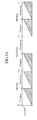
- FIG. 3 shows a diagram representing a relationship between a previous frame and a subsequent frame of a frame that turns on the subfield in one of the two groups.
- the subfields in the first and second groups are turned on to express an image in first and third frames as shown in FIG. 2A, and the subfield in the first group is turned on to express the image in a second frame as shown in FIG. 2B.
- the subfields in the first and second groups are turned on to express an image in the first and third frames, and the subfield in the first group is turned on to express the image in the second frame as shown in FIG. 2C.
- the present invention has been made in an effort to provide a plasma display for preventing a misfiring operation, and a controller and driving method thereof.
- an exemplary driving method for sequentially driving a plasma display by a plurality of subfields divided into first and second subfield groups from one frame, a) it is determined whether at least one subfield to be turned on is included in one subfield group among the first and second subfield groups, b) a subfield turn-on time control signal for controlling a turn-on time of the subfield to be turned on is generated according to a determined result in a), and c) the subfield is turned on at the turn-on time corresponding to the subfield turn-on time control signal.
- the subfield turn-on time control signal for delaying the turn-on time of the subfield to be turned on by a predetermined time may be generated.
- the subfield turn-on time control signal for advancing the turn-on time of the subfield to be turned on by a predetermined time may be generated.
- the subfield turn-on time control signal for turning on the subfield without changing the turn-on time may be generated.
- An exemplary controller of a plasma display driven by a plurality of subfields divided, according to a vertical synchronization signal of a first frequency, into first and second subfield groups from one frame includes a subfield location controller and a subfield data generator.
- the subfield location controller generates a subfield turn-on time control signal for controlling a turn-on time of the subfield according to whether at least one subfield value is included in the first subfield group, the second subfield group, or both subfield groups.
- the subfield data generator transmits the subfield value of the subfield to be turned on to the subfield location controller to express a grayscale for each frame according to the video signal, controls the turn-on time of the subfield according to the subfield turn-on time control signal, and transmits controlled turn-on time to the subfield location controller.
- An exemplary plasma display includes a plasma display panel (PDP), a controller, and a driving circuit unit.
- the PDP includes a first electrode, a second electrode, and a third electrode in a direction crossing the first and second electrodes.
- the controller divides a frame, according to an externally input vertical synchronization signal of a first frequency, into first and second subfield groups respectively including a plurality of subfields, and generates a subfield turn-on time control signal varying according to whether the subfield to be turned on is included in the subfield first group, the second subfield group, or both subfield groups, to express a grayscale for each frame according to an input video signal.
- the driving circuit unit drives the first to third electrodes according to a controlling operation of the controller to change a turn-on time of the subfield according to the subfield turn-on time control signal.
- the subfield turn-on time control signal may delay the turn-on time when the subfields to be turned on are included in the first subfield group, and it may advance the turn-on time when the subfields to be turned on are included in the second subfield group.
- the subfield turn-on time control signal may maintain the turn-on time when the subfields to be turned on are included in the first and second subfields groups.
- the first frequency may be a vertical synchronization frequency of a phase alternate line (PAL) method.
- PAL phase alternate line
- an element when it is described that an element is “coupled” to another element, the element may be “directly coupled” to the other element or “electrically coupled” to the other element through a third element.
- wall charges mentioned in the following description mean charges formed and accumulated on a wall (e.g., a dielectric layer) close to an electrode of a discharge cell.
- a wall charge will be described as being “formed” or “accumulated” on the electrode, although the wall charges do not actually touch the electrodes.
- a wall voltage means a potential difference formed on the wall of the discharge cell by the wall charge.
- a plasma display according to an exemplary embodiment of the present invention, and a controller and a driving method thereof will now be described with reference to the figures.
- FIG. 4 shows a block diagram of the plasma display according to the exemplary embodiment of the present invention.
- the plasma display includes a plasma display panel (PDP) 100, a controller 200, an address electrode driver 300, a scan electrode driver 400, and a sustain electrode driver 500.
- PDP plasma display panel
- the PDP 100 includes a plurality of address electrodes A1 to Am extending in a column direction, and a plurality of sustain and scan electrodes X1 to Xn and Y1 to Yn in pairs extending in a row direction.
- the sustain electrodes X1-Xn are formed in respective correspondence to the scan electrodes Y1 to Yn, and ends of the sustain electrodes X1-Xn are connected in common.
- the PDP 100 includes a substrate (not shown) having the sustain and scan electrodes X1-Xn and Y1 to Yn, and a substrate (not shown) having the address electrodes A1-Am.
- the two substrates are arranged to face each other with a discharge space between them so that the scan electrodes Y1 to Yn and the sustain electrodes X1-Xn may cross the address electrodes A1-Am.
- discharge spaces provided at crossing regions of the address electrodes and X and Y electrodes form discharge cells.
- the controller 200 receives external video signals, and outputs an address driving control signal Sa, a sustain electrode driving control signal Sx, and a scan electrode driving control signal Sy. In addition, the controller 200 divides a frame into a plurality of subfields, and each subfield has a reset period, an address period, and a sustain period in a temporal manner.
- the address electrode driver 300 After receiving the address driving control signal Sa from the controller 200, the address electrode driver 300 applies a display data signal for selecting discharge cells to be displayed to the respective address electrodes A1-Am.
- the scan electrode driver 400 receives the scan electrode driving control signal Sy from the controller 200, and applies the driving voltage to the scan electrode Y.
- the sustain electrode driver 500 receives the sustain electrode driving control signal Sx from the controller 200, and applies a driving voltage to the sustain electrode X.
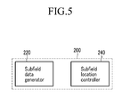
- FIG. 5 shows a block diagram representing the controller of the PDP according to the exemplary embodiment of the present invention.
- the controller 200 of the PDP includes a subfield data generator 220 and a subfield location controller 240.
- the subfield data generator 220 transmits a control signal to the scan electrode driver 400 and the sustain electrode driver 500 so that subfields SF1, SF3, SF5, and SF7 in the first group and the subfields SF2, SF4, SF6, and SF8 are turned on according to the grayscale for each frame.
- the subfield data generator 220 transmits information of the turned on subfield to the subfield location controller 240, receives a subfield turn-on timing control signal generated by the subfield location controller 240, and transmits a control signal for turning on the corresponding subfield to the scan electrode driver 400 and the sustain electrode driver 500.
- the subfield location controller 240 determines whether information on the plurality of subfields received from the subfield data generator 220 includes the subfields of the first and second group, or whether it includes the subfields SF1, SF3, SF5, and SF7 or SF2, SF4, SF6, and SF8 of one of the two groups.
- the subfield location controller 240 generates the subfield turn-on timing control signal for delaying a turn-on time of the subfield by a predetermined time when the input information includes the subfield in the first group, and the subfield location controller 240 generates the subfield turn-on timing control signal for advancing the turn-on time of the subfield by the predetermined time when the information includes the subfield in the second group, and transmits the subfield turn-on timing control signals to the subfield data generator 220.
- the subfield location controller 240 when the received information includes the subfields in the first and second groups, the subfield location controller 240 generates the subfield turn-on timing control signal, but there is no change in the turn-on time of the subfield.
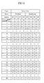
- FIG. 6 shows a diagram representing the grayscales when the subfield in the first group is turned on
- FIG. 7 shows a diagram representing a subfield turn-on controlling operation of the subfield location controller 240 when a video signal having the grayscale shown in FIG. 6 is input.
- the grayscales shown in FIG. 6 correspond to the second frame among the first and third frames shown in FIG. 7, and it is assumed that the video signal having the dark-colored grayscales 1, 4, 5, 16, 17, 20, and 21 are turned on in the second frame.
- the subfield data generator 220 informs the subfield location controller 240 of the turned on subfields SF1, SF3, and SF5, and the subfield location controller 240 delays the turn-on time of the subfield by the predetermined time since the received information of the subfields includes the subfield in the first group.
- FIG. 8 shows a table representing grayscales when the subfield in the second group according to the exemplary embodiment of the present invention are turned on
- FIG. 9 shows a diagram representing a subfield turn-on controlling operation of the subfield location controller 240 when a video signal having the grayscale shown in FIG. 8 is input.
- the grayscales correspond to the second frame among the first and third frames shown in FIG. 9, and video signals having dark-colored grayscales 2, 8, 10, 32, 34, 40, and 42 are turned on in the second frame.
- the subfield data generator 220 informs the subfield location controller 240 of the turned on subfields SF2, SF4, and SF6, and the subfield location controller 240 advanced the turn-on time of the subfield by the predetermined time since the received information of the subfields includes the subfields in the second group.
- FIG. 10 shows a flowchart representing a subfield turn-on time controlling operation of the controller 200 according to the exemplary embodiment of the present invention.
- the subfield data generator 220 receiving the video signal initializes the number N of frames in step S602.
- the number N of frames is exemplarily initialized to be 1 in FIG. 10, but another natural number, a prime number, or a value with a predetermined character (e.g. an alphabet) may be used.
- the controller 200 may perform the subfield turn-on time control operation from the first frame generated by using the input video signal, and the subfield data generator 220 may perform an initialization operation when the number of frames is increased to be higher than a predetermined value since the video signal is continuously input.
- the subfield data generator 220 performing the initialization operation in step S602 transmits a turn-on subfield value to the subfield location controller 240 according to a grayscale to be expressed in a frame according to the video signal, and the subfield location controller 240 determines in step S604 whether the subfield value includes the subfield in the first group and the subfield in the second group.
- the subfield location controller 240 determines in step S606 whether the received subfield value includes the subfield in the first group.
- the subfield location controller 240 When it is determined, according to a determined result in step S606, that the received subfield value includes the subfield in the first group, the subfield location controller 240 generates the subfield turn-on time control signal for delaying the subfield turn-on time by a predetermined time, and transmits it to the subfield data generator 220 in step S608. When it is determined that the received subfield value does not include the subfield in the first group, the subfield location controller 240 determines that it include the subfield value includes the subfield in the second group, generates the subfield turn-on time control signal for advancing the subfield turn-on time by the predetermined time, and transmits it to the subfield data generator 220 in step S610.
- step S606 it may be established to determine whether the received subfield value include the subfield in the second group, and in this case, the steps S608 and S610 are changed from each other.
- the subfield location controller 240 When it is determined, according to the determined result in step S604, that the subfields in the first and second groups of the corresponding frame are turned on, the subfield location controller 240 generates the subfield turn-on time control signal for turning on the corresponding subfield without changing the turn-on time, and transmits it to the subfield data generator 220.
- the subfield data generator 220 receiving the subfield turn-on time control signal in step S604, S608, or S610 transmits a control signal to the scan electrode driver 400 and the sustain electrode driver 500 so that the corresponding subfield is turned on the controlled turn-on time in step S612.
- the subfield data generator 220 determining the turn-on time of the corresponding frame and transmitting the control signal in step S612, increases the number of frames in step S614, and performs the step S604.
- the subfield in one of the first and second groups is turned on. Accordingly, misfiring may be prevented, and the plasma display may be stably driven.
Landscapes
- Engineering & Computer Science (AREA)
- Physics & Mathematics (AREA)
- Computer Hardware Design (AREA)
- General Physics & Mathematics (AREA)
- Theoretical Computer Science (AREA)
- Plasma & Fusion (AREA)
- Power Engineering (AREA)
- Control Of Indicators Other Than Cathode Ray Tubes (AREA)
Abstract
Description
- The present invention relates to a plasma display, and a controller and driving method thereof.
- A plasma display uses a plasma display panel (PDP) that uses plasma generated by a gas discharge process to display characters or images. The PDP includes, depending on its size, more than several scores to millions of pixels arranged in a matrix pattern.
- One frame time is 16.67ms (i.e. 1/60 second) in a national television system committee (NTSC) method using a 60Hz frequency, and one frame time is 20ms (i.e., 1/50 second) in a phase alternate line (PAL) method using a 50Hz frequency.
- Since one frame time of 20ms is long enough so that a person may perceive an image changing in the PAL method, the person may see the screen flickering every 20ms. That is, a flicker phenomenon may occur in the PAL method.
- To prevent the flickering effect, one frame is divided into first and second groups, and subfields having greater weight values are separately applied to the two groups.
- FIG. 1 shows a diagram representing subfield arrangement of one frame in the conventional PAL method.
- As shown in FIG. 1, one frame in the plasma display of the conventional PAL method includes first and second groups, subfields SF1, SF3, SF5, and SF7 are applied to the first group, and subfields SF2, SF4, SF6, and SF8 are applied to the second group. That is, the first and second groups are respectively divided into the plurality of subfields respectively having different luminance weight values, and the respective subfields SF1 to SF8 include address periods A1 to A8 and sustain periods S1 to S8.
- The address periods A1 to A8 are for selecting turn-on/off cells (i.e., cells to be turned on or off) in a panel, and the sustain periods S1 to S8 are for causing a discharge for displaying an image on the discharged cells. Here, lengths of the sustain periods S1 to S8 correspond to weight values of the respective subfields SF1 to SF8, and it is assumed that that the lengths of the sustain periods S1 to S8 are respectively 1T, 2T, 4T, 8T, 16T, 32T, 64T, and 128T. In addition, a reset period (not shown) for initializing a discharge cell may be provided before the address periods A1 to A8.
- Here, a sum of weight values determines a grayscale of the discharge cell to be turned on. As shown in FIG. 1, subfields SF1 to SF8 are arranged in increasing order of weight or in decreasing order of weight.
- In the PAL method shown in FIG. 1, a person may perceive a change of image every 10ms since the subfields having greater weight values are divided into two groups, and therefore the flicker effect may be reduced.
- Changes of luminance according to the arrangement of the subfields forming one frame in the conventional PAL method shown in FIG. 1 are shown in FIG. 2.
- FIG. 2 shows a diagram representing the changes of luminance in one frame in the conventional PAL method.
- In FIG. 2, a one-frame time is 20 ms, and 10ms is respectively applied to the first and second groups. In the first and second groups, since subfields SF1, SF3, SF5, and SF7 and subfields SF2, SF4, SF6, and SF8 are arranged from a low weight value subfield to a high weight value subfield, the luminance is increased at latter subfields of each group.
- In FIG. 2A, subfields in the first and second groups are turned on. In addition, the plasma display may express an image on the PDP by turning on subfield in one of the first and second groups according to the grayscale of the image, which is shown in FIG. 2A and B. That is, the subfield in the first group is turned on in FIG. 2B, and the subfield in the second group is turned on in FIG. 2C.
- FIG. 3 shows a diagram representing a relationship between a previous frame and a subsequent frame of a frame that turns on the subfield in one of the two groups.
- In FIG. 3A, the subfields in the first and second groups are turned on to express an image in first and third frames as shown in FIG. 2A, and the subfield in the first group is turned on to express the image in a second frame as shown in FIG. 2B. In FIG. 3A, the subfields in the first and second groups are turned on to express an image in the first and third frames, and the subfield in the first group is turned on to express the image in the second frame as shown in FIG. 2C.
- In FIG. 3A, since a sustain discharge is generated in the subfield of the first group and it is not generated in the subfield of the second group in the second frame, misfiring may be problematically generated in the first group of the subsequent third frame. In FIG. 3B, a time delay in generating the sustain discharge is generated between the second group of the previous first frame and the second group of the second frame since the sustain discharge is not generated in the subfield of the first group of the second frame, and therefore, the misfiring may be problematically generated in the second group of the second frame.
- The above information disclosed in this Background section is only for enhancement of understanding of the background of the invention and therefore it may contain information that does not form the prior art that is already known in this country to a person of ordinary skilled in the art.
- The present invention has been made in an effort to provide a plasma display for preventing a misfiring operation, and a controller and driving method thereof.
- In an exemplary driving method for sequentially driving a plasma display by a plurality of subfields divided into first and second subfield groups from one frame, a) it is determined whether at least one subfield to be turned on is included in one subfield group among the first and second subfield groups, b) a subfield turn-on time control signal for controlling a turn-on time of the subfield to be turned on is generated according to a determined result in a), and c) the subfield is turned on at the turn-on time corresponding to the subfield turn-on time control signal.
- In b), when it is determined in a) that the subfields to be turned on are included in the first subfield group, the subfield turn-on time control signal for delaying the turn-on time of the subfield to be turned on by a predetermined time may be generated.
- In b), when it is determined in a) that the subfields to be turned on are included in the second subfield group, the subfield turn-on time control signal for advancing the turn-on time of the subfield to be turned on by a predetermined time may be generated.
- In b), when it is determined in a) that the subfields to be turned on are included in the first and second subfield groups, the subfield turn-on time control signal for turning on the subfield without changing the turn-on time may be generated.
- An exemplary controller of a plasma display driven by a plurality of subfields divided, according to a vertical synchronization signal of a first frequency, into first and second subfield groups from one frame includes a subfield location controller and a subfield data generator. The subfield location controller generates a subfield turn-on time control signal for controlling a turn-on time of the subfield according to whether at least one subfield value is included in the first subfield group, the second subfield group, or both subfield groups. The subfield data generator transmits the subfield value of the subfield to be turned on to the subfield location controller to express a grayscale for each frame according to the video signal, controls the turn-on time of the subfield according to the subfield turn-on time control signal, and transmits controlled turn-on time to the subfield location controller.
- An exemplary plasma display includes a plasma display panel (PDP), a controller, and a driving circuit unit. The PDP includes a first electrode, a second electrode, and a third electrode in a direction crossing the first and second electrodes. The controller divides a frame, according to an externally input vertical synchronization signal of a first frequency, into first and second subfield groups respectively including a plurality of subfields, and generates a subfield turn-on time control signal varying according to whether the subfield to be turned on is included in the subfield first group, the second subfield group, or both subfield groups, to express a grayscale for each frame according to an input video signal. The driving circuit unit drives the first to third electrodes according to a controlling operation of the controller to change a turn-on time of the subfield according to the subfield turn-on time control signal.
- The subfield turn-on time control signal may delay the turn-on time when the subfields to be turned on are included in the first subfield group, and it may advance the turn-on time when the subfields to be turned on are included in the second subfield group.
- The subfield turn-on time control signal may maintain the turn-on time when the subfields to be turned on are included in the first and second subfields groups.
- The first frequency may be a vertical synchronization frequency of a phase alternate line (PAL) method.
-
- FIG. 1 shows a diagram representing subfield arrangement of one frame in a conventional PAL method.
- FIGs. 2A to 2C show a diagram representing changes of luminance in one frame in the conventional PAL method.
- FIGs. 3A to 3B show a diagram representing a relationship between a previous frame and a subsequent frame of a frame that turns on a subfield in one of two groups.
- FIG. 4 shows a block diagram of a plasma display according to an exemplary embodiment of the present invention.
- FIG. 5 shows a block diagram representing a controller of a PDP according to the exemplary embodiment of the present invention.
- FIG. 6 shows a diagram representing grayscales when a subfield in a first group is turned on.
- FIG. 7 shows a diagram representing a subfield turn-on controlling operation of a subfield location controller when a video signal having the grayscale shown in FIG. 6 is input.
- FIG. 8 shows a table representing grayscales when the subfield in the second group according to the exemplary embodiment of the present invention is turned on.
- FIG. 9 shows a diagram representing a subfield turn-on controlling operation of a subfield location controller when a video signal having the grayscale shown in FIG. 8 is input.
- FIG. 10 shows a flowchart representing a subfield turn-on time controlling operation of the controller according to the exemplary embodiment of the present invention.
- In the following detailed description, only certain exemplary embodiments of the present invention have been shown and described, simply by way of illustration. As those skilled in the art would realize, the described embodiments may be modified in various different ways, all without departing from the spirit or scope of the present invention. Accordingly, the drawings and description are to be regarded as illustrative in nature and not restrictive. Like reference numerals designate like elements throughout the specification.
- Throughout this specification and the claims which follow, when it is described that an element is "coupled" to another element, the element may be "directly coupled" to the other element or "electrically coupled" to the other element through a third element.
- In addition, wall charges mentioned in the following description mean charges formed and accumulated on a wall (e.g., a dielectric layer) close to an electrode of a discharge cell. A wall charge will be described as being "formed" or "accumulated" on the electrode, although the wall charges do not actually touch the electrodes. Further, a wall voltage means a potential difference formed on the wall of the discharge cell by the wall charge. Throughout this specification and the claims which follow, unless explicitly described to the contrary, the word "comprise", and variations such as "comprises" or "comprising", will be understood to imply the inclusion of stated elements but not the exclusion of any other elements.
- A plasma display according to an exemplary embodiment of the present invention, and a controller and a driving method thereof will now be described with reference to the figures.
- FIG. 4 shows a block diagram of the plasma display according to the exemplary embodiment of the present invention.
- As shown in FIG. 4, the plasma display according to the exemplary embodiment of the present invention includes a plasma display panel (PDP) 100, a
controller 200, anaddress electrode driver 300, ascan electrode driver 400, and a sustainelectrode driver 500. - The
PDP 100 includes a plurality of address electrodes A1 to Am extending in a column direction, and a plurality of sustain and scan electrodes X1 to Xn and Y1 to Yn in pairs extending in a row direction. The sustain electrodes X1-Xn are formed in respective correspondence to the scan electrodes Y1 to Yn, and ends of the sustain electrodes X1-Xn are connected in common. In addition, thePDP 100 includes a substrate (not shown) having the sustain and scan electrodes X1-Xn and Y1 to Yn, and a substrate (not shown) having the address electrodes A1-Am. The two substrates are arranged to face each other with a discharge space between them so that the scan electrodes Y1 to Yn and the sustain electrodes X1-Xn may cross the address electrodes A1-Am. Here, discharge spaces provided at crossing regions of the address electrodes and X and Y electrodes form discharge cells. This formation of theplasma display panel 100 is an example, and another formation of a panel for applying driving waveforms that will be described may be applied to the present invention. - The
controller 200 receives external video signals, and outputs an address driving control signal Sa, a sustain electrode driving control signal Sx, and a scan electrode driving control signal Sy. In addition, thecontroller 200 divides a frame into a plurality of subfields, and each subfield has a reset period, an address period, and a sustain period in a temporal manner. - After receiving the address driving control signal Sa from the
controller 200, theaddress electrode driver 300 applies a display data signal for selecting discharge cells to be displayed to the respective address electrodes A1-Am. - The
scan electrode driver 400 receives the scan electrode driving control signal Sy from thecontroller 200, and applies the driving voltage to the scan electrode Y. - The sustain
electrode driver 500 receives the sustain electrode driving control signal Sx from thecontroller 200, and applies a driving voltage to the sustain electrode X. - FIG. 5 shows a block diagram representing the controller of the PDP according to the exemplary embodiment of the present invention.
- As shown in FIG. 5, the
controller 200 of the PDP according to the exemplary embodiment of the present invention includes asubfield data generator 220 and asubfield location controller 240. - The
subfield data generator 220 transmits a control signal to thescan electrode driver 400 and the sustainelectrode driver 500 so that subfields SF1, SF3, SF5, and SF7 in the first group and the subfields SF2, SF4, SF6, and SF8 are turned on according to the grayscale for each frame. - The
subfield data generator 220 transmits information of the turned on subfield to thesubfield location controller 240, receives a subfield turn-on timing control signal generated by thesubfield location controller 240, and transmits a control signal for turning on the corresponding subfield to thescan electrode driver 400 and the sustainelectrode driver 500. - The
subfield location controller 240 determines whether information on the plurality of subfields received from thesubfield data generator 220 includes the subfields of the first and second group, or whether it includes the subfields SF1, SF3, SF5, and SF7 or SF2, SF4, SF6, and SF8 of one of the two groups. According to a determined result, thesubfield location controller 240 generates the subfield turn-on timing control signal for delaying a turn-on time of the subfield by a predetermined time when the input information includes the subfield in the first group, and thesubfield location controller 240 generates the subfield turn-on timing control signal for advancing the turn-on time of the subfield by the predetermined time when the information includes the subfield in the second group, and transmits the subfield turn-on timing control signals to thesubfield data generator 220. In addition, when the received information includes the subfields in the first and second groups, thesubfield location controller 240 generates the subfield turn-on timing control signal, but there is no change in the turn-on time of the subfield. - The turn-on time of the subfield that is controlled by the
subfield location controller 240 shown in FIG. 5 will now be described with reference to FIG. 6 to FIG. 9. - FIG. 6 shows a diagram representing the grayscales when the subfield in the first group is turned on, and FIG. 7 shows a diagram representing a subfield turn-on controlling operation of the
subfield location controller 240 when a video signal having the grayscale shown in FIG. 6 is input. - The grayscales shown in FIG. 6 correspond to the second frame among the first and third frames shown in FIG. 7, and it is assumed that the video signal having the dark-
colored grayscales - As shown in FIG. 7, the
subfield data generator 220 informs thesubfield location controller 240 of the turned on subfields SF1, SF3, and SF5, and thesubfield location controller 240 delays the turn-on time of the subfield by the predetermined time since the received information of the subfields includes the subfield in the first group. - FIG. 8 shows a table representing grayscales when the subfield in the second group according to the exemplary embodiment of the present invention are turned on, and FIG. 9 shows a diagram representing a subfield turn-on controlling operation of the
subfield location controller 240 when a video signal having the grayscale shown in FIG. 8 is input. - The grayscales correspond to the second frame among the first and third frames shown in FIG. 9, and video signals having dark-
colored grayscales - As shown in FIG. 9, the
subfield data generator 220 informs thesubfield location controller 240 of the turned on subfields SF2, SF4, and SF6, and thesubfield location controller 240 advanced the turn-on time of the subfield by the predetermined time since the received information of the subfields includes the subfields in the second group. - FIG. 10 shows a flowchart representing a subfield turn-on time controlling operation of the
controller 200 according to the exemplary embodiment of the present invention. - Firstly, the
subfield data generator 220 receiving the video signal initializes the number N of frames in step S602. In this case, the number N of frames is exemplarily initialized to be 1 in FIG. 10, but another natural number, a prime number, or a value with a predetermined character (e.g. an alphabet) may be used. In addition, in step S602, while the plasma display is turned on from a standby state, thecontroller 200 may perform the subfield turn-on time control operation from the first frame generated by using the input video signal, and thesubfield data generator 220 may perform an initialization operation when the number of frames is increased to be higher than a predetermined value since the video signal is continuously input. - The
subfield data generator 220 performing the initialization operation in step S602 transmits a turn-on subfield value to thesubfield location controller 240 according to a grayscale to be expressed in a frame according to the video signal, and thesubfield location controller 240 determines in step S604 whether the subfield value includes the subfield in the first group and the subfield in the second group. - When it is determined, according to a determined result in step S604, that the grayscale of the corresponding frame is expressed by the subfield in one of the first and second groups, the
subfield location controller 240 determines in step S606 whether the received subfield value includes the subfield in the first group. - When it is determined, according to a determined result in step S606, that the received subfield value includes the subfield in the first group, the
subfield location controller 240 generates the subfield turn-on time control signal for delaying the subfield turn-on time by a predetermined time, and transmits it to thesubfield data generator 220 in step S608. When it is determined that the received subfield value does not include the subfield in the first group, thesubfield location controller 240 determines that it include the subfield value includes the subfield in the second group, generates the subfield turn-on time control signal for advancing the subfield turn-on time by the predetermined time, and transmits it to thesubfield data generator 220 in step S610. - In addition, in step S606, it may be established to determine whether the received subfield value include the subfield in the second group, and in this case, the steps S608 and S610 are changed from each other.
- When it is determined, according to the determined result in step S604, that the subfields in the first and second groups of the corresponding frame are turned on, the
subfield location controller 240 generates the subfield turn-on time control signal for turning on the corresponding subfield without changing the turn-on time, and transmits it to thesubfield data generator 220. Thesubfield data generator 220 receiving the subfield turn-on time control signal in step S604, S608, or S610 transmits a control signal to thescan electrode driver 400 and the sustainelectrode driver 500 so that the corresponding subfield is turned on the controlled turn-on time in step S612. - The
subfield data generator 220 determining the turn-on time of the corresponding frame and transmitting the control signal in step S612, increases the number of frames in step S614, and performs the step S604. - As described above, in a frame where subfields are divided into first and second groups respectively having different weight values, the subfield in one of the first and second groups is turned on. Accordingly, misfiring may be prevented, and the plasma display may be stably driven.
Claims (9)
- A driving method for sequentially driving a plasma display by a plurality of subfields divided into first and second subfield groups from one frame, the driving method comprising:a) determining whether at least one subfield to be turned on is included in one subfield group among the first and second subfield groups;b) generating a subfield turn-on time control signal for controlling a turn-on time of the subfield to be turned on, according to a determined result in a); andc) turning on the subfield at the turn-on time corresponding to the subfield turn-on time control signal.
- The driving method of claim 1, wherein, in b), when it is determined in a) that the subfields to be turned on are included in the first subfield group, the subfield turn-on time control signal for delaying the turn-on time of the subfield to be turned on by a predetermined time is generated.
- The driving method of claim 1, wherein, in b), when it is determined in a) that the subfields to be turned on are included in the second subfield group, the subfield turn-on time control signal for advancing the turn-on time of the subfield to be turned on by a predetermined time is generated.
- The driving method according to one of claims 1 - 3, wherein, in b), when it is determined in a) that the subfields to be turned on are included in the first and second subfield groups, the subfield turn-on time control signal for turning on the subfield without changing the turn-on time is generated.
- A controller of a plasma display driven by a plurality of subfields divided, according to a vertical synchronization signal of a first frequency, into first and second subfield groups from one frame, the controller comprising:a subfield location controller for generating a subfield turn-on time control signal for controlling a turn-on time of the subfield according to whether at least one subfield value is included in the first subfield group, the second subfield group, or both subfield groups ; anda subfield data generator for transmitting the subfield value of the subfield to be turned on to the subfield location controller to express a grayscale for each frame according to the video signal, controlling the turn-on time of the subfield according to the subfield turn-on time control signal, and transmitting controlled turn-on time to the subfield location controller.
- A plasma display comprising:a plasma display panel (PDP) comprising a first electrode, a second electrode, and a third electrode in a direction crossing the first and second electrodes;the controller of claim 5; anda driving circuit unit for driving the first to third electrodes according to a controlling operation of the controller to change a turn-on time of the subfield according to the subfield turn-on time control signal.
- The plasma display of claim 6, wherein the subfield turn-on time control signal delays the turn-on time when the subfields to be turned on are included in the first subfield group, and it advances the turn-on time when the subfields to be turned on are included in the second subfield group.
- The plasma display of claim 6, wherein the subfield turn-on time control signal maintains the turn-on time when the subfields to be turned on are included in the first and second subfields groups.
- The plasma display of one of the claims 6 to 8, wherein the first frequency is a vertical synchronization frequency of a phase alternate line (PAL) method.
Applications Claiming Priority (1)
| Application Number | Priority Date | Filing Date | Title |
|---|---|---|---|
| KR1020060107747A KR100869797B1 (en) | 2006-11-02 | 2006-11-02 | Plasma display device, control device thereof and driving method thereof |
Publications (2)
| Publication Number | Publication Date |
|---|---|
| EP1918903A1 true EP1918903A1 (en) | 2008-05-07 |
| EP1918903B1 EP1918903B1 (en) | 2009-07-29 |
Family
ID=38057496
Family Applications (1)
| Application Number | Title | Priority Date | Filing Date |
|---|---|---|---|
| EP07101549A Not-in-force EP1918903B1 (en) | 2006-11-02 | 2007-02-01 | Plasma display and controlling device and method thereof |
Country Status (4)
| Country | Link |
|---|---|
| EP (1) | EP1918903B1 (en) |
| KR (1) | KR100869797B1 (en) |
| CN (1) | CN100576298C (en) |
| DE (1) | DE602007001762D1 (en) |
Citations (4)
| Publication number | Priority date | Publication date | Assignee | Title |
|---|---|---|---|---|
| EP1315139A2 (en) | 2001-11-12 | 2003-05-28 | Samsung SDI Co., Ltd. | Image display method and system for plasma display panel |
| EP1450338A2 (en) | 2003-02-18 | 2004-08-25 | Samsung SDI Co., Ltd. | Method and device for displaying an image on a plasma display panel with subfield arrangement dependent on the load ratio of the input video signal |
| US20050062690A1 (en) | 2003-08-05 | 2005-03-24 | Jeong Jae-Seok | Image displaying method and device for plasma display panel |
| US20050073616A1 (en) | 2003-10-01 | 2005-04-07 | Mi-Young Joo | Method and apparatus for reducing flicker when displaying pictures on a plasma display panel |
Family Cites Families (2)
| Publication number | Priority date | Publication date | Assignee | Title |
|---|---|---|---|---|
| KR100502933B1 (en) | 2003-02-18 | 2005-07-21 | 삼성에스디아이 주식회사 | A method for displaying pictures on plasma display panel and an apparatus thereof |
| KR100531488B1 (en) | 2004-04-23 | 2005-11-29 | 엘지전자 주식회사 | Method and Apparatus For Driving Plasma Display Panel |
-
2006
- 2006-11-02 KR KR1020060107747A patent/KR100869797B1/en not_active Expired - Fee Related
-
2007
- 2007-02-01 EP EP07101549A patent/EP1918903B1/en not_active Not-in-force
- 2007-02-01 DE DE602007001762T patent/DE602007001762D1/en active Active
- 2007-02-28 CN CN200710084740A patent/CN100576298C/en not_active Expired - Fee Related
Patent Citations (4)
| Publication number | Priority date | Publication date | Assignee | Title |
|---|---|---|---|---|
| EP1315139A2 (en) | 2001-11-12 | 2003-05-28 | Samsung SDI Co., Ltd. | Image display method and system for plasma display panel |
| EP1450338A2 (en) | 2003-02-18 | 2004-08-25 | Samsung SDI Co., Ltd. | Method and device for displaying an image on a plasma display panel with subfield arrangement dependent on the load ratio of the input video signal |
| US20050062690A1 (en) | 2003-08-05 | 2005-03-24 | Jeong Jae-Seok | Image displaying method and device for plasma display panel |
| US20050073616A1 (en) | 2003-10-01 | 2005-04-07 | Mi-Young Joo | Method and apparatus for reducing flicker when displaying pictures on a plasma display panel |
Also Published As
| Publication number | Publication date |
|---|---|
| CN100576298C (en) | 2009-12-30 |
| KR20080040148A (en) | 2008-05-08 |
| DE602007001762D1 (en) | 2009-09-10 |
| KR100869797B1 (en) | 2008-11-21 |
| EP1918903B1 (en) | 2009-07-29 |
| CN101174378A (en) | 2008-05-07 |
Similar Documents
| Publication | Publication Date | Title |
|---|---|---|
| US20070252788A1 (en) | Plasma Display Device and Driving Method Thereof | |
| KR100603297B1 (en) | Panel driving method, panel driving device and display panel | |
| WO2003032352A2 (en) | Plasma display panel driving method and apparatus | |
| US6756950B1 (en) | Method of driving plasma display panel and apparatus thereof | |
| EP1850313A1 (en) | Display apparatus and method for driving the same | |
| EP1918903B1 (en) | Plasma display and controlling device and method thereof | |
| JP4318666B2 (en) | Plasma display device and driving method thereof | |
| JPH11265163A (en) | Driving method of AC PDP | |
| KR100490635B1 (en) | The plasma display panel and method for driving thereof | |
| JP2002108278A (en) | Plasma display device and driving method thereof | |
| CN101286293A (en) | Plasma display panel and driving method thereof | |
| US20080238823A1 (en) | Plasma display device and driving method thereof | |
| CN100426351C (en) | Plasma display device and driving method thereof | |
| KR100424264B1 (en) | Method for driving plasma display panel for improving initial state | |
| KR100647676B1 (en) | How to Operate Discharge Display Panel with Extended Setting Gradation | |
| KR100581877B1 (en) | Plasma Display Panel Driving Method | |
| KR20050118851A (en) | Plasma display device and driving method thereof | |
| KR100648693B1 (en) | Plasma display device and driving method thereof | |
| US20080174582A1 (en) | Plasma display device and driving method thereof | |
| EP1923854A2 (en) | Plasma display and driving method | |
| EP1772843A2 (en) | Plasma display device and its driving method | |
| KR100805546B1 (en) | Driving method of plasma display device and plasma display panel | |
| KR100603308B1 (en) | Plasma Display Panel Driving Method | |
| KR100637248B1 (en) | Driving method of discharge display panel for efficient reduction of addressing power | |
| JP2008225044A (en) | Image signal processor |
Legal Events
| Date | Code | Title | Description |
|---|---|---|---|
| PUAI | Public reference made under article 153(3) epc to a published international application that has entered the european phase |
Free format text: ORIGINAL CODE: 0009012 |
|
| 17P | Request for examination filed |
Effective date: 20070201 |
|
| AK | Designated contracting states |
Kind code of ref document: A1 Designated state(s): AT BE BG CH CY CZ DE DK EE ES FI FR GB GR HU IE IS IT LI LT LU LV MC NL PL PT RO SE SI SK TR |
|
| AX | Request for extension of the european patent |
Extension state: AL BA HR MK RS |
|
| 17Q | First examination report despatched |
Effective date: 20080702 |
|
| AKX | Designation fees paid |
Designated state(s): DE FR GB HU |
|
| GRAP | Despatch of communication of intention to grant a patent |
Free format text: ORIGINAL CODE: EPIDOSNIGR1 |
|
| GRAS | Grant fee paid |
Free format text: ORIGINAL CODE: EPIDOSNIGR3 |
|
| GRAA | (expected) grant |
Free format text: ORIGINAL CODE: 0009210 |
|
| AK | Designated contracting states |
Kind code of ref document: B1 Designated state(s): DE FR GB HU |
|
| REG | Reference to a national code |
Ref country code: GB Ref legal event code: FG4D |
|
| REF | Corresponds to: |
Ref document number: 602007001762 Country of ref document: DE Date of ref document: 20090910 Kind code of ref document: P |
|
| REG | Reference to a national code |
Ref country code: HU Ref legal event code: AG4A Ref document number: E006803 Country of ref document: HU |
|
| PLBE | No opposition filed within time limit |
Free format text: ORIGINAL CODE: 0009261 |
|
| STAA | Information on the status of an ep patent application or granted ep patent |
Free format text: STATUS: NO OPPOSITION FILED WITHIN TIME LIMIT |
|
| 26N | No opposition filed |
Effective date: 20100503 |
|
| PGFP | Annual fee paid to national office [announced via postgrant information from national office to epo] |
Ref country code: GB Payment date: 20110126 Year of fee payment: 5 |
|
| PGFP | Annual fee paid to national office [announced via postgrant information from national office to epo] |
Ref country code: FR Payment date: 20120103 Year of fee payment: 6 |
|
| PGFP | Annual fee paid to national office [announced via postgrant information from national office to epo] |
Ref country code: HU Payment date: 20120109 Year of fee payment: 6 |
|
| PGFP | Annual fee paid to national office [announced via postgrant information from national office to epo] |
Ref country code: DE Payment date: 20111221 Year of fee payment: 6 |
|
| GBPC | Gb: european patent ceased through non-payment of renewal fee |
Effective date: 20130201 |
|
| PG25 | Lapsed in a contracting state [announced via postgrant information from national office to epo] |
Ref country code: HU Free format text: LAPSE BECAUSE OF NON-PAYMENT OF DUE FEES Effective date: 20130202 |
|
| REG | Reference to a national code |
Ref country code: FR Ref legal event code: ST Effective date: 20131031 |
|
| REG | Reference to a national code |
Ref country code: DE Ref legal event code: R119 Ref document number: 602007001762 Country of ref document: DE Effective date: 20130903 |
|
| PG25 | Lapsed in a contracting state [announced via postgrant information from national office to epo] |
Ref country code: FR Free format text: LAPSE BECAUSE OF NON-PAYMENT OF DUE FEES Effective date: 20130228 Ref country code: DE Free format text: LAPSE BECAUSE OF NON-PAYMENT OF DUE FEES Effective date: 20130903 Ref country code: GB Free format text: LAPSE BECAUSE OF NON-PAYMENT OF DUE FEES Effective date: 20130201 |