EP1918572A1 - Fuel rail - Google Patents
Fuel rail Download PDFInfo
- Publication number
- EP1918572A1 EP1918572A1 EP06022239A EP06022239A EP1918572A1 EP 1918572 A1 EP1918572 A1 EP 1918572A1 EP 06022239 A EP06022239 A EP 06022239A EP 06022239 A EP06022239 A EP 06022239A EP 1918572 A1 EP1918572 A1 EP 1918572A1
- Authority
- EP
- European Patent Office
- Prior art keywords
- piece
- fuel rail
- internal combustion
- combustion engine
- fuel
- Prior art date
- Legal status (The legal status is an assumption and is not a legal conclusion. Google has not performed a legal analysis and makes no representation as to the accuracy of the status listed.)
- Granted
Links
Images
Classifications
-
- F—MECHANICAL ENGINEERING; LIGHTING; HEATING; WEAPONS; BLASTING
- F02—COMBUSTION ENGINES; HOT-GAS OR COMBUSTION-PRODUCT ENGINE PLANTS
- F02M—SUPPLYING COMBUSTION ENGINES IN GENERAL WITH COMBUSTIBLE MIXTURES OR CONSTITUENTS THEREOF
- F02M55/00—Fuel-injection apparatus characterised by their fuel conduits or their venting means; Arrangements of conduits between fuel tank and pump F02M37/00
- F02M55/02—Conduits between injection pumps and injectors, e.g. conduits between pump and common-rail or conduits between common-rail and injectors
- F02M55/025—Common rails
-
- F—MECHANICAL ENGINEERING; LIGHTING; HEATING; WEAPONS; BLASTING
- F02—COMBUSTION ENGINES; HOT-GAS OR COMBUSTION-PRODUCT ENGINE PLANTS
- F02M—SUPPLYING COMBUSTION ENGINES IN GENERAL WITH COMBUSTIBLE MIXTURES OR CONSTITUENTS THEREOF
- F02M69/00—Low-pressure fuel-injection apparatus ; Apparatus with both continuous and intermittent injection; Apparatus injecting different types of fuel
- F02M69/46—Details, component parts or accessories not provided for in, or of interest apart from, the apparatus covered by groups F02M69/02 - F02M69/44
- F02M69/462—Arrangement of fuel conduits, e.g. with valves for maintaining pressure in the pipes after the engine being shut-down
- F02M69/465—Arrangement of fuel conduits, e.g. with valves for maintaining pressure in the pipes after the engine being shut-down of fuel rails
Definitions
- the invention relates to a fuel rail for an internal combustion engine.
- US 4,457,280 discloses a fuel rail assembly for holding a plurality of electromechanical fuel injector elements in aligned positions on an internal combustion engine.
- the beam portion of the fuel rail is comprised of two elongated manifold members with overlapping sides brazed together.
- One of the manifold members has a series of planar sides with apertures for retaining and precisely aligning a plurality of injector cups.
- the injector cups are mounted with their cavities in close proximity to the inside of the fuel rail.
- the fuel rail is structurally designed for ease of assembly and to provide adequate rigidity without excessive weight.
- the invention is distinguished by a fuel rail for an internal combustion engine.
- the fuel rail comprises a first and a second side-piece, a middle-piece, at least one connection at each of the pieces, and an inlet for supplying the fuel rail with fuel.
- the middle-piece is arranged between the first and the second side-piece moveable relative to the first and the second side-piece.
- the middle-piece is hydraulically and sealingly coupled to the first and the second side-piece.
- the connections are arranged for connecting each piece of the fuel rail to at least one injection valve of the internal combustion engine.
- the movability of the middle-piece relative to the side-pieces enables to use the fuel rail for different internal combustion engines.
- the movability of the middle-piece relative to the side-pieces enables to use the fuel rail for different internal combustion engines which have different distances from one injection valve of the internal combustion engine to another injection valve of the internal combustion engine.
- the middle-piece is partially arranged in the first and/or the second side-piece. This contributes to hydraulically and sealingly coupling the middle-piece to the side-pieces in an easy way.
- the first and/or second side-piece is partially arranged in the middle-piece. This contributes to hydraulically and sealingly coupling the middle-piece to the side-pieces in an easy way.
- the middle-piece and/or the first and/or the second side-piece comprises a bracket for fixing the fuel rail to the internal combustion engine. This enables to fix the fuel rail to the internal combustion engine in an easy way. Further, this may contribute to stabilize the fuel rail.
- the fuel rail comprises at least one supporting bracket for fixing the middle-piece to the first and/or the second side-piece. This contributes to stabilize the fuel rail.
- the middle-piece and the first and/or the second side-piece comprise an overlapping area.
- a surface of the overlapping area comprises a given roughness for sealingly coupling the middle-piece to the first and, respectively, the second side-piece. This very effectively contributes to sealingly coupling the middle-piece to the first and, respectively, the second side-piece.
- a sealing is arranged between the middle-piece and the side-pieces at the surface of the overlapping area. The sealing and the given roughness of the surface in the overlapping area may contribute very effectively to the proper sealed coupling.
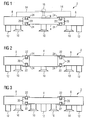
- a fuel rail 2 (figure 1) comprises a middle-piece 4, a first side-piece 6 and a second side-piece 8.
- the fuel rail 2 is arranged at an internal combustion engine.
- the fuel rail 2 is arranged for storing fuel with a given pressure and to supply at least one, preferably more injection valves of the internal combustion engine with fluid at the given pressure.
- Each of the pieces of the fuel rail 2 comprises at least one connection 10 for connecting the fuel rail 2 to the injection valves.
- the first and/or the second side-piece 6, 8 comprise a bracket 12.
- the brackets 12 are arranged for fixing the fuel rail 2 to the internal combustion engine.
- the fuel rail 2 may comprise different devices for fixing the fuel rail 2 to the internal combustion engine.
- the middle-piece 4 and/or the first and/or the second side-piece 6, 8 may comprise a supporting bracket 14 which may be fixed to the middle-piece by a screw 16 and a corresponding thread 18 at the middle-piece 4 and, respectively, at the first and/or the second side-piece 6, 8.
- the supporting bracket 14 comprises a slot for taking in the screw 16.
- the middle-piece 4 is at least partially arranged in the first and/or second side-piece 6, 8.
- the middle-piece 4 is arranged in the first and/or second side-piece 6, 8 in such a way that it is movable relative to the first and/or the second side-piece 6, 8.
- the middle-piece 4 is movable relative to the first and/or the second side-piece 6, 8 in a direction which is parallel to the long side of the middle-piece 4.
- the pieces of the fuel rail 2 are for example tube-shaped
- the middle-piece 4 is movable relative to the first and/or the second side-piece 6, 8 in a direction parallel to an axis of the middle-piece 4.
- the pieces of the fuel rail 2 may be shaped rectangular.
- the middle-piece 4 may comprise a recess 20 for partially taking in a sealing 22.
- the recess 20 comprises a groove at an outer shell of the middle-piece 4 next to an axial end of the middle-piece 4.
- the sealing 22 preferably is an O-ring. If the middle-piece 4 and the first and the second side-piece 6, 8 are not tube shaped, for example rectangular, the sealing 22 has a corresponding form which guarantees a hydraulically sealed coupling of the middle-piece 4 to the first and/or the second side-piece 6, 8.
- the middle-piece 4 and the side-pieces comprise an overlapping area.
- the sealing 22 is arranged in the overlapping area.
- a surface of the overlapping area, at which the sealing 22 is arranged comprises a given roughness.
- the given roughness and the sealing 22 may contribute to improve the sealing of the coupling between the middle-piece 4 and the side-pieces.
- the middle-piece 4 is adjusted relative to the first and the second side-piece 6, 8 in such a way that the connections 10 fit to the positions of the injection valves of the internal combustion engine.
- the fuel rail 2 preferably is adjusted by moving the middle-piece 4 relative to the first and/or the second side-piece 6, 8.
- the internal combustion engine comprises six or twelve injection valves two or, respectively, four fuel rails 2 may be combined.
- the fuel rail 2 may comprise further side-pieces for adjusting the fuel rail 2 to an internal combustion engine with more than three injection valves.
- first and/or the second side-piece 6, 8 are partially arranged in the middle-piece 4 (figure 2).
- the first side-piece 6 may be partially arranged in the middle-piece 4 and the middle-piece 4 may be partially arranged in the second side-piece 8.
- the middle-piece 4 my comprise more than one, in particular two connections 10 (figure 3). This enables to use the fuel rail 2 for internal combustion engines which comprise four, eight, or twelve injection valves in an easy way.
- the third embodiment of the fuel rail 2 enables to adjust the outer connections 10 of the fuel rail 2 to the position of the injection valves of the internal combustion engine.
- the invention is not restricted by the explained embodiments.
- the embodiments may be combined.
- the second and/or the third and/or further embodiments of the fuel rail 2 may comprise the supporting brackets 14.
- the middle-piece 4, the first and/or the second side-piece 6, 8 may comprise further brackets 12 and/or further connections 10.
- further side-pieces may be arranged for adjusting the fuel rail 2 to internal combustion engines which comprise more than three injection valves.
Landscapes
- Engineering & Computer Science (AREA)
- Chemical & Material Sciences (AREA)
- Combustion & Propulsion (AREA)
- Mechanical Engineering (AREA)
- General Engineering & Computer Science (AREA)
- Fuel-Injection Apparatus (AREA)
Abstract
Description
- The invention relates to a fuel rail for an internal combustion engine.
-
US 4,457,280 discloses a fuel rail assembly for holding a plurality of electromechanical fuel injector elements in aligned positions on an internal combustion engine. The beam portion of the fuel rail is comprised of two elongated manifold members with overlapping sides brazed together. One of the manifold members has a series of planar sides with apertures for retaining and precisely aligning a plurality of injector cups. To prevent vapor locks the injector cups are mounted with their cavities in close proximity to the inside of the fuel rail. The fuel rail is structurally designed for ease of assembly and to provide adequate rigidity without excessive weight. - It is an object of the invention to create a fuel rail for an internal combustion engine which enables a simple use of the fuel rail for different internal combustion engines.
- The object is achieved by the features of claim 1. Advantageous embodiments of the invention are given in the subclaims.
- The invention is distinguished by a fuel rail for an internal combustion engine. The fuel rail comprises a first and a second side-piece, a middle-piece, at least one connection at each of the pieces, and an inlet for supplying the fuel rail with fuel. The middle-piece is arranged between the first and the second side-piece moveable relative to the first and the second side-piece. The middle-piece is hydraulically and sealingly coupled to the first and the second side-piece. The connections are arranged for connecting each piece of the fuel rail to at least one injection valve of the internal combustion engine.
- The movability of the middle-piece relative to the side-pieces enables to use the fuel rail for different internal combustion engines. In particular, the movability of the middle-piece relative to the side-pieces enables to use the fuel rail for different internal combustion engines which have different distances from one injection valve of the internal combustion engine to another injection valve of the internal combustion engine.
- In an advantageous embodiment of the fuel rail the middle-piece is partially arranged in the first and/or the second side-piece. This contributes to hydraulically and sealingly coupling the middle-piece to the side-pieces in an easy way.
- In a further advantageous embodiment of the fuel rail the first and/or second side-piece is partially arranged in the middle-piece. This contributes to hydraulically and sealingly coupling the middle-piece to the side-pieces in an easy way.
- In a further advantageous embodiment of the fuel rail the middle-piece and/or the first and/or the second side-piece comprises a bracket for fixing the fuel rail to the internal combustion engine. This enables to fix the fuel rail to the internal combustion engine in an easy way. Further, this may contribute to stabilize the fuel rail.
- In a further advantageous embodiment of the fuel rail the fuel rail comprises at least one supporting bracket for fixing the middle-piece to the first and/or the second side-piece. This contributes to stabilize the fuel rail.
- In a further advantageous embodiment of the fuel rail the middle-piece and the first and/or the second side-piece comprise an overlapping area. A surface of the overlapping area comprises a given roughness for sealingly coupling the middle-piece to the first and, respectively, the second side-piece. This very effectively contributes to sealingly coupling the middle-piece to the first and, respectively, the second side-piece. Preferably, a sealing is arranged between the middle-piece and the side-pieces at the surface of the overlapping area. The sealing and the given roughness of the surface in the overlapping area may contribute very effectively to the proper sealed coupling.
- The invention is explained in the following with the help of schematic drawings.
- These are as follows:
- figure 1
- a first embodiment of a fuel rail,
- figure 2
- a second embodiment of the fuel rail,
- figure 3
- a third embodiment of the fuel rail.
- Elements with the same design or function that appear in the different illustrations are identified by the same reference characters.
- A fuel rail 2 (figure 1) comprises a middle-
piece 4, a first side-piece 6 and a second side-piece 8. Preferably, thefuel rail 2 is arranged at an internal combustion engine. Thefuel rail 2 is arranged for storing fuel with a given pressure and to supply at least one, preferably more injection valves of the internal combustion engine with fluid at the given pressure. - Each of the pieces of the
fuel rail 2 comprises at least oneconnection 10 for connecting thefuel rail 2 to the injection valves. The first and/or the second side-piece bracket 12. Thebrackets 12 are arranged for fixing thefuel rail 2 to the internal combustion engine. Alternatively, thefuel rail 2 may comprise different devices for fixing thefuel rail 2 to the internal combustion engine. - For fixing the middle-
piece 4 to the first and/or the second side-piece piece 4 and/or the first and/or the second side-piece bracket 14 which may be fixed to the middle-piece by ascrew 16 and a corresponding thread 18 at the middle-piece 4 and, respectively, at the first and/or the second side-piece bracket 14 comprises a slot for taking in thescrew 16. To fix the middle-piece 4 to the first and/or the second side-piece - Preferably, the middle-
piece 4 is at least partially arranged in the first and/or second side-piece piece 4 is arranged in the first and/or second side-piece piece piece 4 is movable relative to the first and/or the second side-piece piece 4. If the pieces of thefuel rail 2 are for example tube-shaped, the middle-piece 4 is movable relative to the first and/or the second side-piece piece 4. Alternatively, the pieces of thefuel rail 2 may be shaped rectangular. - For sealingly and hydraulically coupling the middle-
piece 4 to the first and/or the second side-piece piece 4 may comprise arecess 20 for partially taking in a sealing 22. Preferably, therecess 20 comprises a groove at an outer shell of the middle-piece 4 next to an axial end of the middle-piece 4. If the middle-piece 4 and the first and the second side-piece piece 4 and the first and the second side-piece piece 4 to the first and/or the second side-piece - The middle-
piece 4 and the side-pieces comprise an overlapping area. The sealing 22 is arranged in the overlapping area. Preferably, a surface of the overlapping area, at which the sealing 22 is arranged, comprises a given roughness. The given roughness and the sealing 22 may contribute to improve the sealing of the coupling between the middle-piece 4 and the side-pieces. - If the
fuel rail 2 is arranged at an internal combustion engine with three injection valves, the middle-piece 4 is adjusted relative to the first and the second side-piece connections 10 fit to the positions of the injection valves of the internal combustion engine. Thefuel rail 2 preferably is adjusted by moving the middle-piece 4 relative to the first and/or the second side-piece fuel rails 2 may be combined. In an alternative embodiment thefuel rail 2 may comprise further side-pieces for adjusting thefuel rail 2 to an internal combustion engine with more than three injection valves. - In a second embodiment of the
fuel rail 2 the first and/or the second side-piece piece 6 may be partially arranged in the middle-piece 4 and the middle-piece 4 may be partially arranged in the second side-piece 8. - In a third embodiment of the
fuel rail 2 the middle-piece 4 my comprise more than one, in particular two connections 10 (figure 3). This enables to use thefuel rail 2 for internal combustion engines which comprise four, eight, or twelve injection valves in an easy way. The third embodiment of thefuel rail 2 enables to adjust theouter connections 10 of thefuel rail 2 to the position of the injection valves of the internal combustion engine. - The invention is not restricted by the explained embodiments. For example, the embodiments may be combined. For example, the second and/or the third and/or further embodiments of the
fuel rail 2 may comprise the supportingbrackets 14. Further, the middle-piece 4, the first and/or the second side-piece further brackets 12 and/orfurther connections 10. Further, in all embodiments further side-pieces may be arranged for adjusting thefuel rail 2 to internal combustion engines which comprise more than three injection valves.
Claims (6)
- Fuel rail (2) for an internal combustion engine comprising- a first and a second side-piece (6, 8),- a middle-piece (4) which is arranged between the first and the second side-piece (6, 8) movable relative to the first and the second side-piece (6, 8) and which is hydraulically and sealingly coupled to the first and the second side-piece (6, 8),- at least one connection (10) at each of the pieces for connecting each piece to at least one injection valve of the internal combustion engine,- an inlet for supplying the fuel rail (2) with fuel.
- Fuel rail (2) in accordance with claim 1 wherein the middle-piece (4) is partially arranged in the first and/or the second side-piece (6, 8).
- Fuel rail (2) in accordance with claim 1 wherein the first and/or the second side-piece (6, 8) is partially arranged in the middle-piece (4).
- Fuel rail (2) in accordance with one of the preceding claims with the middle-piece (4) and/or the first and/or the second side-piece (6, 8) comprising a bracket (12) for fixing the fuel rail (2) to the internal combustion engine.
- Fuel rail (2) in accordance with one of the preceding claims comprising at least one supporting bracket (14) for fixing the middle-piece (4) to the first and/or the second side-piece (6, 8).
- Fuel rail (2) in accordance with one of the preceding claims with the middle-piece (4) and the first and/or the second side-piece (6, 8) comprising an overlapping area and with a surface (24) of the overlapping area comprising a given roughness for sealingly coupling the middle-piece (4) to the first and, respectively, the second side-piece (6, 8).
Priority Applications (2)
| Application Number | Priority Date | Filing Date | Title |
|---|---|---|---|
| EP20060022239 EP1918572B1 (en) | 2006-10-24 | 2006-10-24 | Fuel rail |
| DE200660009821 DE602006009821D1 (en) | 2006-10-24 | 2006-10-24 | Fuel pressure accumulator |
Applications Claiming Priority (1)
| Application Number | Priority Date | Filing Date | Title |
|---|---|---|---|
| EP20060022239 EP1918572B1 (en) | 2006-10-24 | 2006-10-24 | Fuel rail |
Publications (2)
| Publication Number | Publication Date |
|---|---|
| EP1918572A1 true EP1918572A1 (en) | 2008-05-07 |
| EP1918572B1 EP1918572B1 (en) | 2009-10-14 |
Family
ID=37575108
Family Applications (1)
| Application Number | Title | Priority Date | Filing Date |
|---|---|---|---|
| EP20060022239 Not-in-force EP1918572B1 (en) | 2006-10-24 | 2006-10-24 | Fuel rail |
Country Status (2)
| Country | Link |
|---|---|
| EP (1) | EP1918572B1 (en) |
| DE (1) | DE602006009821D1 (en) |
Families Citing this family (1)
| Publication number | Priority date | Publication date | Assignee | Title |
|---|---|---|---|---|
| RU2576759C1 (en) * | 2015-03-20 | 2016-03-10 | Федеральное государственное унитарное предприятие "Центральный ордена Трудового Красного Знамени научно-исследовательский автомобильный и автомоторный институт "НАМИ" | Device for distribution of fuel to internal combustion engine injectors |
Citations (5)
| Publication number | Priority date | Publication date | Assignee | Title |
|---|---|---|---|---|
| DE19936685A1 (en) * | 1999-08-04 | 2001-02-22 | Bosch Gmbh Robert | High pressure fuel accumulator |
| EP1188919A2 (en) * | 2000-09-18 | 2002-03-20 | Hitachi, Ltd. | Fuel supply system |
| WO2004013487A1 (en) * | 2002-08-02 | 2004-02-12 | Wärtsilä Finland Oy | Fuel supply system |
| DE102004055266A1 (en) * | 2004-11-17 | 2006-05-18 | Robert Bosch Gmbh | Fuel injection system with multiple accumulators |
| DE102005012165A1 (en) * | 2005-03-17 | 2006-09-28 | L'orange Gmbh | Fuel storage for fuel injection system of internal combustion engine of motor vehicle, has segments, of which two are connected with remaining for supplying fuel over linking lines, if break or leakage occurs in one segment |
-
2006
- 2006-10-24 EP EP20060022239 patent/EP1918572B1/en not_active Not-in-force
- 2006-10-24 DE DE200660009821 patent/DE602006009821D1/en active Active
Patent Citations (5)
| Publication number | Priority date | Publication date | Assignee | Title |
|---|---|---|---|---|
| DE19936685A1 (en) * | 1999-08-04 | 2001-02-22 | Bosch Gmbh Robert | High pressure fuel accumulator |
| EP1188919A2 (en) * | 2000-09-18 | 2002-03-20 | Hitachi, Ltd. | Fuel supply system |
| WO2004013487A1 (en) * | 2002-08-02 | 2004-02-12 | Wärtsilä Finland Oy | Fuel supply system |
| DE102004055266A1 (en) * | 2004-11-17 | 2006-05-18 | Robert Bosch Gmbh | Fuel injection system with multiple accumulators |
| DE102005012165A1 (en) * | 2005-03-17 | 2006-09-28 | L'orange Gmbh | Fuel storage for fuel injection system of internal combustion engine of motor vehicle, has segments, of which two are connected with remaining for supplying fuel over linking lines, if break or leakage occurs in one segment |
Also Published As
| Publication number | Publication date |
|---|---|
| DE602006009821D1 (en) | 2009-11-26 |
| EP1918572B1 (en) | 2009-10-14 |
Similar Documents
| Publication | Publication Date | Title |
|---|---|---|
| EP2875233B1 (en) | Fuel rail assembly | |
| EP2103805B1 (en) | Fuel rail damping assembly including an insert | |
| EP2075455B1 (en) | Self-damping fuel rail | |
| US7856962B2 (en) | Fuel system for a direct injection internal combustion engine | |
| CN102345544B (en) | Fuel supply system of vee engine | |
| US20150136084A1 (en) | Fuel distributor | |
| EP2753820B1 (en) | Fuel injector and fuel injector assembly | |
| US7143749B1 (en) | Apparatus and method for securing a fuel rail to an engine | |
| US20090255511A1 (en) | Fuel delivery system | |
| EP2093414A1 (en) | Coupling device | |
| EP2347861B1 (en) | Injector removal tool | |
| JP4758746B2 (en) | Common rail fuel supply system | |
| WO2009058283A1 (en) | Fuel system having a one-piece hollow tube connection | |
| EP3312408B1 (en) | Structure of gdi fuel delivery pipe | |
| EP2251542A1 (en) | Fuel injector assembly and cylinder head side member | |
| EP1918572B1 (en) | Fuel rail | |
| US7347190B1 (en) | Fuel injector rail assembly for direct injection of fuel | |
| EP3353409B1 (en) | Fuel rail assembly and method for manufacturing a fuel rail assembly | |
| EP2372140B1 (en) | Coupling device | |
| JP5537316B2 (en) | Delivery pipe fixing structure | |
| CN114174671B (en) | Modular and scalable rail fuel system architecture | |
| US6990959B1 (en) | Fuel rail delivery system arrangement | |
| US7584746B1 (en) | Fuel rail radiated noise reduction | |
| CN111433450A (en) | Device for common rail fuel injection system | |
| JP3805640B2 (en) | Piping structure of fuel injection pipe |
Legal Events
| Date | Code | Title | Description |
|---|---|---|---|
| PUAI | Public reference made under article 153(3) epc to a published international application that has entered the european phase |
Free format text: ORIGINAL CODE: 0009012 |
|
| AK | Designated contracting states |
Kind code of ref document: A1 Designated state(s): AT BE BG CH CY CZ DE DK EE ES FI FR GB GR HU IE IS IT LI LT LU LV MC NL PL PT RO SE SI SK TR |
|
| AX | Request for extension of the european patent |
Extension state: AL BA HR MK RS |
|
| 17P | Request for examination filed |
Effective date: 20081107 |
|
| RAP1 | Party data changed (applicant data changed or rights of an application transferred) |
Owner name: CONTINENTAL AUTOMOTIVE GMBH |
|
| AKX | Designation fees paid |
Designated state(s): DE FR IT |
|
| GRAP | Despatch of communication of intention to grant a patent |
Free format text: ORIGINAL CODE: EPIDOSNIGR1 |
|
| GRAS | Grant fee paid |
Free format text: ORIGINAL CODE: EPIDOSNIGR3 |
|
| GRAA | (expected) grant |
Free format text: ORIGINAL CODE: 0009210 |
|
| AK | Designated contracting states |
Kind code of ref document: B1 Designated state(s): DE FR IT |
|
| REF | Corresponds to: |
Ref document number: 602006009821 Country of ref document: DE Date of ref document: 20091126 Kind code of ref document: P |
|
| PLBE | No opposition filed within time limit |
Free format text: ORIGINAL CODE: 0009261 |
|
| STAA | Information on the status of an ep patent application or granted ep patent |
Free format text: STATUS: NO OPPOSITION FILED WITHIN TIME LIMIT |
|
| 26N | No opposition filed |
Effective date: 20100715 |
|
| PGFP | Annual fee paid to national office [announced via postgrant information from national office to epo] |
Ref country code: FR Payment date: 20121031 Year of fee payment: 7 Ref country code: DE Payment date: 20121031 Year of fee payment: 7 |
|
| PGFP | Annual fee paid to national office [announced via postgrant information from national office to epo] |
Ref country code: IT Payment date: 20121024 Year of fee payment: 7 |
|
| REG | Reference to a national code |
Ref country code: DE Ref legal event code: R119 Ref document number: 602006009821 Country of ref document: DE Effective date: 20140501 |
|
| REG | Reference to a national code |
Ref country code: FR Ref legal event code: ST Effective date: 20140630 |
|
| PG25 | Lapsed in a contracting state [announced via postgrant information from national office to epo] |
Ref country code: IT Free format text: LAPSE BECAUSE OF NON-PAYMENT OF DUE FEES Effective date: 20131024 Ref country code: DE Free format text: LAPSE BECAUSE OF NON-PAYMENT OF DUE FEES Effective date: 20140501 Ref country code: FR Free format text: LAPSE BECAUSE OF NON-PAYMENT OF DUE FEES Effective date: 20131031 |