EP1918565B1 - Zünderanode für wiederzündbare Raketenbrennkammern - Google Patents
Zünderanode für wiederzündbare Raketenbrennkammern Download PDFInfo
- Publication number
- EP1918565B1 EP1918565B1 EP07020364.1A EP07020364A EP1918565B1 EP 1918565 B1 EP1918565 B1 EP 1918565B1 EP 07020364 A EP07020364 A EP 07020364A EP 1918565 B1 EP1918565 B1 EP 1918565B1
- Authority
- EP
- European Patent Office
- Prior art keywords
- anode
- ignition
- ignition anode
- previous
- frontal area
- Prior art date
- Legal status (The legal status is an assumption and is not a legal conclusion. Google has not performed a legal analysis and makes no representation as to the accuracy of the status listed.)
- Not-in-force
Links
- 238000002485 combustion reaction Methods 0.000 claims description 11
- 239000007787 solid Substances 0.000 claims 1
- 230000003628 erosive effect Effects 0.000 description 7
- 238000002347 injection Methods 0.000 description 3
- 239000007924 injection Substances 0.000 description 3
- 239000001301 oxygen Substances 0.000 description 3
- 229910052760 oxygen Inorganic materials 0.000 description 3
- UFHFLCQGNIYNRP-UHFFFAOYSA-N Hydrogen Chemical compound [H][H] UFHFLCQGNIYNRP-UHFFFAOYSA-N 0.000 description 2
- QVGXLLKOCUKJST-UHFFFAOYSA-N atomic oxygen Chemical compound [O] QVGXLLKOCUKJST-UHFFFAOYSA-N 0.000 description 2
- 239000001257 hydrogen Substances 0.000 description 2
- 229910052739 hydrogen Inorganic materials 0.000 description 2
- 230000035515 penetration Effects 0.000 description 2
- 230000000750 progressive effect Effects 0.000 description 2
- 230000007704 transition Effects 0.000 description 2
- 241000272194 Ciconiiformes Species 0.000 description 1
- 238000011161 development Methods 0.000 description 1
- 230000018109 developmental process Effects 0.000 description 1
- 238000010304 firing Methods 0.000 description 1
- 238000007373 indentation Methods 0.000 description 1
- 230000001788 irregular Effects 0.000 description 1
- 239000000203 mixture Substances 0.000 description 1
- JTJMJGYZQZDUJJ-UHFFFAOYSA-N phencyclidine Chemical compound C1CCCCN1C1(C=2C=CC=CC=2)CCCCC1 JTJMJGYZQZDUJJ-UHFFFAOYSA-N 0.000 description 1
- 239000010970 precious metal Substances 0.000 description 1
- 239000002760 rocket fuel Substances 0.000 description 1
Images



Classifications
-
- F—MECHANICAL ENGINEERING; LIGHTING; HEATING; WEAPONS; BLASTING
- F02—COMBUSTION ENGINES; HOT-GAS OR COMBUSTION-PRODUCT ENGINE PLANTS
- F02K—JET-PROPULSION PLANTS
- F02K9/00—Rocket-engine plants, i.e. plants carrying both fuel and oxidant therefor; Control thereof
- F02K9/94—Re-ignitable or restartable rocket- engine plants; Intermittently operated rocket-engine plants
-
- F—MECHANICAL ENGINEERING; LIGHTING; HEATING; WEAPONS; BLASTING
- F02—COMBUSTION ENGINES; HOT-GAS OR COMBUSTION-PRODUCT ENGINE PLANTS
- F02K—JET-PROPULSION PLANTS
- F02K9/00—Rocket-engine plants, i.e. plants carrying both fuel and oxidant therefor; Control thereof
- F02K9/95—Rocket-engine plants, i.e. plants carrying both fuel and oxidant therefor; Control thereof characterised by starting or ignition means or arrangements
Definitions
- the invention relates to a detonator anode in particular for re-ignitable rocket combustion chambers according to the preamble of claim 1.
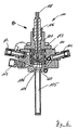
- the prior art discloses an ignition system from Stork® Product Engineering BV under the name EGOX / GH2 VINCI EM Igniter. It is an igniter for re-ignitable rocket combustion chambers, wherein a gaseous hydrogen-oxygen mixture is ignited by means of an electric ignition. Such an igniter 100 is shown in a longitudinal section in the FIG. 6 shown schematically.
- the igniter 100 has an igniter housing 101 and a spark plug device 102.
- a Zündereinspritzkopf 103 which forms a Zündmischhunt 104 together with the igniter housing 101.
- the Zündmischhunt 104 opens into a Zündflammrohr 105, which projects into the combustion chamber of the rocket to be ignited.
- the spark plug device 102 has a spark plug 106 disposed in a spark plug clamping ring 107.
- the spark plug 106 has a terminal end 108 for connection to an ignition voltage source (not shown).
- connection end 108 Opposite to the connection end 108 sits a detonator anode 109 which forms an annular gap 110 together with the igniter injection head 103 and points with its end face into the ignition mixing chamber 104.
- a connection piece 111 for a hydrogen supply and a connection piece 112 for an oxygen supply is attached on the igniter housing 101.
- measuring devices 113 are provided, for example to measure a Zündmischhuntwandtemperatur.
- the igniter anode 109 according to the prior art is in FIG. 6a shown enlarged in a partial longitudinal section.
- the igniter anode 109 has a substantially cylindrical base body 120 with a first free end 121. Opposite the first free end 121 of the cylindrical base body 120 passes into a constricted portion 122, which initially narrows and to an anode head portion 123 extended, wherein the anode head portion 123 has an enlarged compared to the cylindrical base body 120 diameter.
- the anode head portion 123 has a free end 124 which is formed by a plane end face 125 and an obtuse chamfer 126. The free end 124 thus has a single annular edge 126a.
- the plane end face 125 and the flat-angle chamfer 126 form a firing end face, which in the assembled state points into the igniter mixing chamber 104.
- the ignition anode 109 in the cylindrical main body 120 has a blind recess 128 by means of which it is connected to the spark plug 106 by suitable fastening means.
- the US 5,563,469 discloses a fuse anode having various layers of precious metals deposited on the surface thereof. Wells have been cut into these applied layers. These recesses go through the entire igniter anode with a uniform depth.
- the DE 41 40 834 A1 discloses a spark plug for internal combustion engines.
- indentations are introduced into the ignition anode, which are formed as radially outwardly running recesses or concentric recessed circles, each with a constant depth.
- the DE 10 2004 032 723 A1 discloses a spark plug in the igniter anodes recesses are formed with different geometries and each with a constant depth.
- the US 5,821,676 discloses a fuse anode formed as a truncated cone with depressions of constant depth on the conical surface.
- the EP 1 515 594 A2 discloses a spark plug for plasma ignition, with multiple tips on the ignitor anode surface.
- the object of the invention is therefore to provide a detonator anode for re-ignitable rocket combustion chambers, which has a reduced tendency to erosion damage to the Zündstirn preparation and a reduced erosion of the Zündstirn preparation with progressive fuze operation. Furthermore, a more uniform anode erosion over the Zündstirn preparation should be achieved with increasing operating time. In addition, an increased security of the reignition in flight operation is to be ensured, so that a functional risk of the detonator is minimized.
- the distribution at which points the spark breaks through is such that preferably at the edge, which forms the narrowest spark gap, the spark breaks through. If one edge is eroded by burning, another edge forms the narrowest spark gap and is thus the edge at which the spark is most likely to skip. This makes it possible to achieve a uniform burnup of the anode by sparking at the respective highest edge of the end face. Furthermore, there is an enlarged Zündstirn Chemistry because of the bumps. In particular, by V-notches, a defined increase in the surface can be achieved. This results in a much improved spark penetration on the edges over the service life, which minimizes the overall risk of the detonator.
- An igniter anode 1 has a fuze anode body 2 with a cylinder portion 3 with a constricted portion 4 and an anode head portion 5.
- the anode head portion 5 has a larger diameter than the cylinder portion 3.
- the cylinder portion 3 has a free end 6.
- Opposite the free end 6 of the anode head portion 5 has an anode end face 7.
- the anode end face 7 has peripherally circumferentially a flat chamfer 8, so that an annular edge 9 is formed.
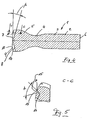
- the anode end face 7 and the chamfer 8 on a plurality of edges 10, which in the embodiment according to the FIGS. 1 to 5 are formed by a plurality of depressions 11.
- a plurality of further edges 10 may also be formed by a plurality of elevations (not shown) which protrude beyond the anode end face 7.
- the recesses 11 and elevations (not shown) may be arranged regularly and / or irregularly distributed over the anode end face 7.
- the depressions are V-shaped in cross-section and extend radially outwards from a center 12 of the anode end surface 7, so that 5 V-shaped cutouts 14 are present in an edge region 13 of the anode head section.
- the depressions 11 are in the embodiment according to FIGS. 1 to 5 regularly arranged in a radiating manner distributed over the surface of the fuze anode front side and each have an angle ⁇ of 60 ° between them.
- Each recess 11 has inclined boundary walls 15, which form the V-shaped cross-section of the depression and meet in the region of a recess base line 16.
- the recess base line 16 extends from the center 12 of the anode end face 7 inclined toward the edge region 13 of the anode head section 5, in particular inclined by an angle ⁇ , wherein the angle ⁇ 10 ° to 20 °, in particular 12 ° to 17 °, particularly preferably 15 °.
- the angle ⁇ is chosen such that the baseline 16 in a longitudinal section according to FIG. 4 passes through the igniter anode 1 parallel to the chamfer 8. This ensures that the recesses 11 have a constant depth in the radial direction outwardly from the annular edge 9.
- the range of 0 mm to +0.1 mm, in particular 0 mm to 0.02 mm has proven.
- the base lines 16 of the recesses have a transition, wherein the transition is about 0 mm to +0.1 mm, in particular 0 mm to +0.5 mm.
- a wall angle ⁇ between the walls 15 of a V-shaped recess 11 a range of 45 ° to 75 ° has been proven, with a range of 55 ° to 65 °, in particular 60 ° is preferred.
- the plasma image beats surprisingly easily with such shaped edges 10 and ensures reliable ignition or reignition of the rocket combustion chamber.
- an increased ignition safety is achieved by the provision of a plurality of edges 10, which act as a preferred flashpoint for plasma bursts. Furthermore, a uniform wear of the igniter anode 1 is ensured due to the large number of existing recess 11 (notches) and resulting edges 10, because occurring erosion by plasma breaks evenly distributed over the fuze anode end face 7 and the chamfer 8.
- edges 10 are provided, wherein the edges 10, as in the embodiment according to the FIGS. 1 to 5 are formed by depressions 11.
- more edges 10 by evenly or non-uniformly distributed elevations from the A-node face 7, 9 to provide.
- the depressions 11 as well as the elevations may be distributed uniformly or non-uniformly over the anode end face 7, 8.
- regularly star-shaped arrangement pattern of the wells 11 are also grid-shaped or otherwise grid-shaped arrangements, eg with square, rectangular or diamond-shaped grid pattern possible. Of course, this also applies to surveys that may be provided.
- a surface of the anode end face 7, 8 which is shaped irregularly from elevations and depressions 11 can be formed, for example, in which the anode end face 7 is designed as a fracture surface (not shown).
- a fracture surface it could be provided, for example, first to produce a symmetrical body consisting of two cylindrical sections 3, two constricted sections 4 and two anode head sections 5, which are connected to one another in the region of the anode head end face 7.
- the chamfer 8 could be introduced in the form of a puncture and the two bodies are violently broken at this notch, so that in the area of the fuze anode end face 7 an irregular fracture contour is formed.
- This fracture contour is characterized by sharp-edged elevations and depressions, which provides a plurality of edges to ensure a safe ignition or run-up of the plasma arc.
Landscapes
- Engineering & Computer Science (AREA)
- Chemical & Material Sciences (AREA)
- Combustion & Propulsion (AREA)
- Mechanical Engineering (AREA)
- General Engineering & Computer Science (AREA)
- Spark Plugs (AREA)
- Aiming, Guidance, Guns With A Light Source, Armor, Camouflage, And Targets (AREA)
Description
- Die Erfindung betrifft eine Zünderanode insbesondere für wiederzündbare Raketenbrennkammern nach dem Oberbegriff des Anspruchs 1.
- Aus dem Stand der Technik ist ein Zündsystem der Firma Stork ® Product Engineering B.V. unter dem Namen EGOX/GH2 VINCI EM Igniter bekannt. Es handelt sich hierbei um einen Zünder für wiederzündbare Raketenbrennkammern, wobei mittels einer elektrischen Zündung ein gasförmiges Wasserstoff-Sauerstoffgemisch gezündet wird. Ein derartiger Zünder 100 ist in einer Längsschnittdarstellung in der
Figur 6 schematisch gezeigt. - Der Zünder 100 besitzt ein Zündergehäuse 101 und eine Zündkerzeneinrichtung 102. Im Zündergehäuse 101 sitzt ein Zündereinspritzkopf 103, der zusammen mit dem Zündergehäuse 101 eine Zündmischkammer 104 bildet. Die Zündmischkammer 104 mündet in ein Zündflammrohr 105, welches in die Brennkammer der zu zündenden Rakete ragt. Die Zündkerzeneinrichtung 102 besitzt eine Zündkerze 106, welche in einem Zündkerzenklemmring 107 angeordnet ist. Die Zündkerze 106 besitzt ein Anschlussende 108 zur Verbindung mit einer Zündspannungsquelle (nicht gezeigt). Gegenüberliegend zum Anschlussende 108 sitzt eine Zünderanode 109, welche zusammen mit dem Zündereinspritzkopf 103 einen Ringspalt 110 bildet und mit ihrer Stirnseite in die Zündmischkammer 104 weist. Am Zündergehäuse 101 ist ein Anschlussstutzen 111 für eine Wasserstoffzuführung und ein Anschlussstutzen 112 für eine Sauerstoffzuführung angebracht. Weiterhin sind Messvorrichtungen 113 vorgesehen, beispielsweise um eine Zündmischkammerwandtemperatur zu messen.
- Die Zünderanode 109 gemäß dem Stand der Technik ist in
Figur 6a in einem Teillängsschnitt vergrößert dargestellt. Die Zünderanode 109 besitzt einen im Wesentlichen zylindrischen Grundkörper 120 mit einem ersten freien Ende 121. Gegenüberliegend zum ersten freien Ende 121 geht der zylindrische Grundkörper 120 in einen eingeschnürten Abschnitt 122 über, welcher sich zunächst verengt und zu einem Anodenkopfabschnitt 123 hin erweitert, wobei der Anodenkopfabschnitt 123 einen im Vergleich zum zylindrischen Grundköper 120 vergrößerten Durchmesser besitzt. Der Anodenkopfabschnitt 123 besitzt ein freies Ende 124, welches durch eine plane Stirnfläche 125 und eine stumpfwinklige Anfasung 126 gebildet wird. Das freie Ende 124 besitzt somit eine einzige Ringkante 126a. Die plane Stirnfläche 125 und die flachwinklige Anfasung 126 bilden eine Zündstirnfläche, die im zusammengebauten Zustand in die Zündermischkammer 104 weist. Eine Außenseite 127 des Anodenkopfabschnittes 123 bildet zusammen mit einer korrespondierenden Bohrung im Zündeinspritzkopf 103 den Ringspalt 110. Vom freien Ende 121 her besitzt die Zündanode 109 im zylindrischen Grundkörper 120 eine Sacklochausnehmung 128 mittels der sie mit geeigneten Befestigungsmitteln zusammenwirkend mit der Zündkerze 106 verbunden ist. - Ein derartiger Zünder für wiederzündbare Raketenbrennkammern hat sich bewährt. Bei einer Vielzahl von Wiederzündvorgängen der Raketenbrennkammer ist jedoch eine fortschreitende Erosion an der Zündstirnfläche zu beobachten. Ebenso ist ein erhöhter Verschleiß in Folge von Abbrand festzustellen. Beim Abschalten der Raketenbrennkammer bildet sich eine Oxidschicht an der Zündstirnfläche, welche beim Wiederzünden der Brennkammer das Hochlaufen des Plasmafunkens verschlechtert. Hieraus resultiert ein mögliches erhöhtes Funktionsrisiko.
- Ferner sind aus dem Stand der Technik verschiedene Weiterbildungen von Zündanodenflächen bekannt, die eine Strukturierung der Zündanodenflächen vorsehen.
- Die
US 5,563,469 offenbart eine Zünderanode, auf deren Oberfläche verschiedene Schichten von Edelmetallen aufgebracht sind. In diese aufgebrachten Schichten sind Vertiefungen hineingeschnitten worden. Diese Vertiefungen durchlaufen dabei die gesamte Zünderanode mit einer gleichmäßigen Tiefe. - Die
DE 41 40 834 A1 offenbart eine Zündkerze für Verbrennungsmotoren. Bei dieser Zündkerze sind Vertiefungen in der Zündanode eingebracht, die als radial auswärts laufende Vertiefungen oder konzentrische Vertiefungs-Kreise mit jeweils konstanter Tiefe ausgebildet sind. - Die
DE 10 2004 032 723 A1 offenbart eine Zündkerze, in deren Zünderanoden Vertiefungen mit unterschiedlichen Geometrien und mit jeweils konstanter Tiefe ausgebildet sind. - Die
US 5,821,676 offenbart eine Zünderanode, die als Kegelstumpf mit Vertiefungen mit konstanter Tiefe an der Kegelmantelfläche ausgebildet ist. - Weiterhin offenbart die
EP 0 350 152 A2 eine Zündkerze für den Einsatz mit Raketentreibstoff. - Die
EP 1 515 594 A2 offenbart eine Zündkerze zur Plasmazündung, mit mehreren Spitzen auf der Zünderanodenfläche. - Aufgabe der Erfindung ist es daher, eine Zünderanode für wiederzündbare Raketenbrennkammern anzugeben, welche eine verminderte Neigung zu Erosionsschäden an der Zündstirnfläche und einen verminderten Abbrand der Zündstirnfläche bei fortschreitendem Zünderbetrieb besitzt. Weiterhin soll bei fortschreitender Betriebsdauer ein gleichmäßigerer Anodenabbrand über die Zündstirnfläche erzielt werden. Außerdem soll eine erhöhte Sicherheit des Wiederzündens im Flugbetrieb sichergestellt werden, so dass ein Funktionsrisiko des Zünders minimiert ist.
- Diese Aufgabe werden mit einer Zünderanode, mit den Merkmalen des Anspruchs 1 gelöst. Vorteilhafte Ausführungsformen sind in den Unteransprüchen angegeben.
- Bei der Erfindung ist von besonderem Vorteil, dass durch eine unebene, insbesondere scharfkantig unebene Stirnflächengestaltung der Zünderanode mit zumindest einer insbesondere scharfkantigen, gratfreien Kante ein sogenanntes Hochlaufen des Plasmafunkens beim Wiederzünden erheblich erleichtert wird, auch wenn eine Oxidschicht an der Zündstirnfläche vorhanden ist. Der Grund hierfür wird darin gesehen, dass ein Plasmafunke leichter an einer Kante, insbesondere scharfkantigen, gratfreien Kante durchschlägt als an einer flachen Oberfläche. Weiterhin wird als vorteilhaft angesehen, dass durch das Vorsehen einer Vielzahl, das heißt mehr als einer Kante, bevorzugt scharfkantigen Kanten der Zündfunke immer wieder an unterschiedlichen Stellen an der Zündanodenstirnfläche durchschlägt und somit auch an unterschiedlichen Stellen für Abbrand sorgt. Die Verteilung, an welchen Stellen der Zündfunke durchschlägt ist dabei derart, dass bevorzugt an der Kante, die den engsten Zündspalt bildet der Funke durchschlägt. Wird eine Kante durch Abbrand etwas abgetragen, bildet eine andere Kante den engsten Zündspalt und ist somit die Kante an der der Funke am wahrscheinlichsten überspringt. Hierdurch gelingt es, einen gleichmäßigen Abbrand der Anode durch Funkenbildung an der jeweils erhabensten Kante der Stirnfläche zu erreichen. Weiterhin existiert wegen der Unebenheiten eine vergrößerte Zündstirnfläche. Insbesondere durch V-Kerben kann eine definierte Vergrößerung der Oberfläche erreicht werden. Hieraus resultiert somit über die Betriebsdauer ein wesentlich verbessertes Funkendurchschlagen auf den Kanten, was insgesamt das Funktionsrisiko des Zünders minimiert.
- Im Folgenden wird die Erfindung anhand der Zeichnung beispielhaft näher erläutert:
- Es zeigen
- Figur 1:
- eine erfindungsgemäße Zünderanode in einer Perspektivansicht;
- Figur 2:
- die Zünderanode gemäß
Figur 1 in einer Seitenansicht; - Figur 3:
- die Zünderanode gemäß
Figur 1 in einer Ansicht auf die Zünderstirnseite; - Figur 4:
- die Zünderanode gemäß
Figur 1 in einem Längsschnitt; - Figur 5:
- die Zünderanode gemäß
Figur 1 in einem Detailschnitt im Bereich des Zündanodenkopfes entlang der Linie C-C ausFigur 4 ; - Figur 6:
- Stand der Technik;
- Figur 6a:
- Stand der Technik.
- Eine erfindungsgemäße Zünderanode 1 besitzt einen Zünderanodenkörper 2 mit einem Zylinderabschnitt 3 mit einem eingeschnürten Abschnitt 4 und einem Anodenkopfabschnitt 5. Der Anodenkopfabschnitt 5 besitzt einen größeren Durchmesser als der Zylinderabschnitt 3. Der Zylinderabschnitt 3 weist ein freies Ende 6 auf. Gegenüberliegend zum freien Ende 6 besitzt der Anodenkopfabschnitt 5 eine Anodenstirnfläche 7. Die Anodenstirnfläche 7 besitzt randlich umlaufend eine flache Anfasung 8, so dass eine Ringkante 9 ausgebildet ist. Erfindungsgemäß weist die Anodenstirnfläche 7 und die Anfasung 8 eine Vielzahl von Kanten 10 auf, welche im Ausführungsbeispiel gemäß der
Figuren 1 bis 5 durch eine Vielzahl von Vertiefungen 11 gebildet sind. Selbstverständlich kann eine Vielzahl von weiteren Kanten 10 auch durch eine Vielzahl von Erhebungen (nicht gezeigt), welche über die Anodenstirnfläche 7 herausragen, gebildet sein. Die Vertiefungen 11 und Erhebungen (nicht gezeigt) können regelmäßig und/oder unregelmäßig über die Anodenstirnfläche 7 verteilt angeordnet sein. - Im Ausführungsbeispiel gemäß
Figur 1 sind die Vertiefungen im Querschnitt V-förmig ausgebildet und erstrecken sich von einem Zentrum 12 der Anodenstirnfläche 7 radial nach außen, so dass in einem Randbereich 13 des Anodenkopfabschnittes 5 V-förmige Ausschnitte 14 vorhanden sind. Die Vertiefungen 11 sind im Ausführungsbeispiel gemäßFiguren 1 bis 5 regelmäßig strahlenförmig über die Oberfläche der Zünderanodenstirnseite verteilt angeordnet und weisen zwischen sich jeweils einen Winkel γ von 60° auf. Jede Vertiefung 11 besitzt geneigte Begrenzungswandungen 15, welche den V-förmigen Querschnitt der Vertiefung ausbilden und sich im Bereich einer Vertiefungsgrundlinie 16 treffen. Die Vertiefungsgrundlinie 16 verläuft vom Zentrum 12 der Anodenstirnfläche 7 geneigt zum Randbereich 13 des Anodenkopfabschnittes 5 hin, insbesondere um einen Winkel β geneigt, wobei der Winkel β 10° bis 20°, insbesondere 12° bis 17°, besonders bevorzugt 15° beträgt. Besonders bevorzugt ist der Winkel β derart gewählt, dass die Grundlinie 16 in einem Längsschnitt gemäßFigur 4 durch die Zünderanode 1 parallel zur Anfasung 8 verläuft. Hierdurch wird erreicht, dass die Vertiefungen 11 in Radialrichtung nach außen ab der Ringkante 9 eine konstante Tiefe besitzen. - Um ein Hochlaufen bzw. Durchschlagen eines Plasmafunkens sicherzustellen, sind die Kanten 10, welche durch die Vertiefungen 11, die Anodenstirnfläche 7 und die Anfasungen 8 gebildet werden, scharfkantig, insbesondere gratfrei scharfkantig ausgebildet. Als besonders bevorzugtes Maß für die Gratfreiheit hat sich der Bereich von 0 mm bis +0,1 mm, insbesondere 0 mm bis 0,02 mm bewährt.
- Weiterhin hat sich als vorteilhaft herausgestellt, dass die Grundlinien 16 der Vertiefungen einen Übergang aufweisen, wobei der Übergang etwa 0 mm bis +0,1 mm, insbesondere 0 mm bis +0,5 mm beträgt. Für die Wahl eines Wandungswinkels α zwischen den Wandungen 15 einer V-förmigen Vertiefung 11 hat sich ein Bereich von 45° bis 75° bewährt, wobei ein Bereich von 55° bis 65°, insbesondere 60° bevorzugt ist. Hierdurch entstehen stumpfwinklige Kanten 10, die aber wesentlich spitzwinkliger sind als die umlaufende Ringkante 9. Der Plasmafunke schlägt bei derart ausgebildeten Kanten 10 überraschend leicht durch und sorgt für ein sicheres Zünden bzw. Wiederzünden der Raketenbrennkammer.
- Bei der Erfindung ist von besonderem Vorteil, das durch das Vorsehen einer Vielzahl von Kanten 10, welche als bevorzugte Durchschlagsorte für Plasmafunken fungieren, eine erhöhte Zündsicherheit erreicht ist. Weiterhin ist aufgrund der Vielzahl der vorhandenen Vertiefung 11 (Kerben) und hieraus resultierenden Kanten 10 eine gleichmäßige Abnutzung der Zünderanode 1 gewährleistet, weil auftretende Erosion durch Plasmafunken gleichmäßig über die Zünderanodenstirnfläche 7 und die Anfasung 8 verteilt erfolgt.
- Erfindungswesentlich ist, das ein Vielzahl von Kanten 10 zur Verfügung gestellt wird, wobei die Kanten 10, wie im Ausführungsbeispiel gemäß den
Figuren 1 bis 5 durch Vertiefungen 11 gebildet werden. Gleichwohl ist es jedoch auch möglich, weitere Kanten 10 durch gleichmäßig oder ungleichmäßig verteilte Erhebungen aus der A-nodenstirnfläche 7, 9 zur Verfügung zu stellen. Ebenfalls können die Vertiefungen 11 wie auch die Erhebungen gleichmäßig oder ungleichmäßig über die Anodenstirnfläche 7, 8 verteilt angeordnet sein. Neben dem in denFiguren 1 bis 5 dargestellten regelmäßig sternförmigen Anordungsmuster der Vertiefungen 11 sind auch gitterförmige oder anderweitig rasterförmige Anordnungen, z.B. mit quadratischem, rechteckigem oder rautenförmigem Rastermuster möglich. Dies gilt selbstverständlich auch für eventuell vorgesehene Erhebungen. - Weiterhin kann eine unregelmäßig aus Erhebungen und Vertiefungen 11 geformte Oberfläche der Anodenstirnfläche 7, 8 ausgebildet werden, beispielsweise in dem die Anodenstirnfläche 7 als Bruchfläche (nicht gezeigt) ausgebildet ist. Zur Herstellung einer solchen Bruchfläche könnte beispielsweise vorgesehen sein, zunächst einen symmetrischen Körper bestehend aus zwei zylindrischen Abschnitten 3, zwei eingeschnürten Abschnitten 4 und zwei Anodenkopfabschnitten 5 herzustellen, welche im Bereich der Anodenkopfstirnfläche 7 miteinander verbunden sind. Anschließend könnte die Anfasung 8 in Form eines Einstiches eingebracht werden und an dieser Kerbstelle die beiden Körper gewaltsam gebrochen werden, so dass im Bereich der Zünderanodenstirnfläche 7 eine unregelmäßige Bruchkontur entsteht. Diese Bruchkontur ist durch scharfkantige Erhebungen und Vertiefungen gekennzeichnet, welche eine Vielzahl von Kanten zur Verfügung stellt, um ein sicheres Zünden bzw. Hochlaufen des Plasmafunkens zu gewährleisten.
- Weiterhin ist bei der Erfindung von Vorteil, das durch eine Führung des Hochspannungsfunkens entlang der Kanten 10, insbesondere entlang der Kerbkanten ein gleichmäßigerer Anodenabbrand erfolgt. Die Sicherheit der Wiederzündung ist erhöht, so dass ein geringeres Funktionsrisiko gegenüber dem Stand der Technik verwirklicht ist. Bei symmetrischer Anordnung der Kanten 10 über die Oberfläche der Anodenstirnfläche 7 ist ein symmetrischer Abbrand der Anode 1 aufgrund der Funkenführung an den Kanten 10 gewährleistet. Weiterhin ist eine Vergrößerung der Anodenstirnfläche durch die Kerben und Kanten 10 gegeben.
-
- 1
- Zünderanode
- 2
- Zünderanodenkörper
- 3
- zylindrischer Abschnitt
- 4
- eingeschnürten Abschnitt
- 5
- Anodenkopfabschnitt
- 6
- freies Ende
- 7
- Anodenstirnfläche
- 8
- flache Anfasung
- 9
- Ringkante
- 10
- Kanten
- 11
- Vertiefungen
- 12
- Zentrum
- 13
- Randbereich
- 14
- V-förmige Ausschnitte
- 15
- Begrenzungswandungen
- 16
- Vertiefungsgrundlinie
- 100
- Zünder
- 101
- Zündergehäuse
- 102
- Zündkerzenvorrichtung bzw. Zündkerzeneinrichtung
- 103
- Zündereinspritzkopf
- 104
- Zündbrennkammer
- 105
- Zündflammrohr
- 106
- Zündkerze
- 107
- Zündkerzenklemmring
- 108
- Anschlussende
- 109
- Zünderanonde
- 110
- Ringspalt
- 111
- Anschlussstutzen für Wasserstoffzuführung
- 112
- Anschlussstutzen für Sauerstoffzuführung
- 113
- Messvorrichtungen
- 120
- zylindrischer Grundkörper
- 121
- freies Ende
- 122
- eingeschnürter Abschnitt
- 123
- Andodenkopfabschnitt
- 124
- freies Ende
- 125
- plane Stirnfläche bzw. Anodenstirnfläche
- 126
- flachwinklige Anfasung
- 126a
- Ringkante
- 127
- Außenseite
- 128
- Sacklochausnehmung
Claims (13)
- Zünderanode, insbesondere für eine Zündeinrichtung einer wiederzündbaren Raketenbrennkammer, mit einem rotationssymmetrischen Zünderanodenkörper (2) mit einer Symmetrieachse, der eine Anodenstirnfläche (7, 8) mit einer die Symmetrieachse randlich umlaufenden Anfasung (8) unter Ausbildung einer Ringkante (9) aufweist, wobei die Anodenstirnfläche (7, 8) zusätzlich zu der Ringkante (9) eine Vielzahl von Kanten (10) aufweist die, ausgehend von der Symmetrieachse, durch radial nach außen verlaufende Vertiefungen (11) in der Zünderanodenstirnfläche (7, 8) gebildet sind, dadurch gekennzeichnet, dass die Vertiefungen (11) sich radial nach außen vertiefend ausgebildet sind.
- Zünderanode nach Anspruch 1, dadurch gekennzeichnet, dass die Kanten (10) scharfkantig ausgebildet sind.
- Zünderanode nach Anspruch 1 und/oder 2, dadurch gekennzeichnet, dass die Kanten gratfrei bis +0,1 mm, insbesondere gratfrei bis +0,02 mm ausgebildet sind.
- Zünderanode nach einem oder mehreren der vorangegangenen Ansprüche, dadurch gekennzeichnet, dass weitere Kanten (10) durch Vorsprünge in der Zünderanodenstirnfläche (7, 8) gebildet sind.
- Zünderanode nach einem oder mehreren der vorangegangenen Ansprüche, dadurch gekennzeichnet, dass die Vertiefungen (11) im Querschnitt V-förmig ausgebildet sind und einen Wandungswinkel α von 45° bis 75°, besonders bevorzugt von 55° bis 65°, insbesondere 60° haben.
- Zünderanode nach einem oder mehreren der vorangegangenen Ansprüche, dadurch gekennzeichnet, dass die Vertiefungen (11) gleichmäßig über die Zünderanodenstirnfläche (7, 8) verteilt sind und sternförmig von einem Zentrum (12) der Zünderanodenstirnfläche (7, 8) radial nach außen verlaufen.
- Zünderanode nach einem oder mehreren der vorangegangenen Ansprüche, dadurch gekennzeichnet, dass ein Winkel β zwischen einer Grundlinie (16) der Vertiefung (11) und der Zünderanodenstirnfläche (7) 10° bis 20°, insbesondere 12° bis 17°, besonders bevorzugt 15° beträgt.
- Zünderanode nach einem oder mehreren der vorangegangenen Ansprüche, dadurch gekennzeichnet, dass ein Winkel γ zwischen zwei benachbarten Vertiefungen (11) in radialer Richtung 60° beträgt.
- Zünderanode nach einem oder mehreren der vorangegangenen Ansprüche, dadurch gekennzeichnet, dass Grundlinien (16) im Bereich des Grundes der Vertiefungen (11) einen Übergang bis +0,1 mm, insbesondere bis +0,05 mm besitzen.
- Zünderanode nach einem oder mehreren der vorangegangenen Ansprüche, dadurch gekennzeichnet, dass der Zünderanodenkörper (2) einen zylindrischen Abschnitt (3), einen abgeschnürten Abschnitt (4) und einen Anodenkopfabschnitt (5) aufweist.
- Zünderanode nach einem oder mehreren der vorangegangenen Ansprüche, dadurch gekennzeichnet, dass der Anodenkopfabschnitt (5) im Durchmesser größer ist als der zylindrische Abschnitt (3).
- Zünderanode nach einem oder mehreren der vorangegangenen Ansprüche, dadurch gekennzeichnet, dass die Zündanodenstirnfläche (7) randlich umlaufend eine flache Anfasung (8) aufweist, so dass eine Ringkante (9) gebildet ist.
- Zünderanode nach einem oder mehreren der vorangegangenen Ansprüche, dadurch gekennzeichnet, dass die Zünderanode (1) als Massivkörper ausgebildet ist.
Applications Claiming Priority (1)
| Application Number | Priority Date | Filing Date | Title |
|---|---|---|---|
| DE102006052171A DE102006052171B4 (de) | 2006-11-02 | 2006-11-02 | Zünderanode für wiederzündbare Raketenbrennkammern |
Publications (3)
| Publication Number | Publication Date |
|---|---|
| EP1918565A2 EP1918565A2 (de) | 2008-05-07 |
| EP1918565A3 EP1918565A3 (de) | 2011-07-27 |
| EP1918565B1 true EP1918565B1 (de) | 2016-08-31 |
Family
ID=38980949
Family Applications (1)
| Application Number | Title | Priority Date | Filing Date |
|---|---|---|---|
| EP07020364.1A Not-in-force EP1918565B1 (de) | 2006-11-02 | 2007-10-18 | Zünderanode für wiederzündbare Raketenbrennkammern |
Country Status (3)
| Country | Link |
|---|---|
| US (1) | US7956522B2 (de) |
| EP (1) | EP1918565B1 (de) |
| DE (1) | DE102006052171B4 (de) |
Families Citing this family (2)
| Publication number | Priority date | Publication date | Assignee | Title |
|---|---|---|---|---|
| CN111120112B (zh) * | 2019-12-04 | 2022-06-14 | 中国人民解放军空军工程大学 | 基于燃烧室二次流的多阳极滑动弧等离子体点火器及点火方法 |
| CN115559832A (zh) * | 2022-10-26 | 2023-01-03 | 北京航天试验技术研究所 | 一种气氢气氧小型火炬点火器结构 |
Family Cites Families (9)
| Publication number | Priority date | Publication date | Assignee | Title |
|---|---|---|---|---|
| US2946912A (en) * | 1959-06-18 | 1960-07-26 | Gen Motors Corp | Spark plugs |
| JPH0656136B2 (ja) * | 1987-02-26 | 1994-07-27 | 三菱重工業株式会社 | 点火器 |
| JPH0633672Y2 (ja) * | 1988-07-06 | 1994-08-31 | 日本特殊陶業株式会社 | 極低温液体水素・液体酸素燃料用イグナイタプラグ |
| US5563469A (en) * | 1989-12-27 | 1996-10-08 | Nippondenso Co., Ltd. | Spark plug for internal combustion engine |
| DE4140834A1 (de) * | 1990-12-11 | 1992-06-17 | Sei Young Kim | Zuendkerze fuer verbrennungsmotoren |
| US5821676A (en) * | 1994-09-12 | 1998-10-13 | General Motors Corporation | Spark plug with grooved, tapered center electrode |
| US5892319A (en) * | 1996-01-04 | 1999-04-06 | Rossi; Paul | Top and side firing spark plug |
| FR2859869B1 (fr) * | 2003-09-12 | 2006-01-20 | Renault Sa | Systeme de generation de plasma. |
| DE102004032723B4 (de) * | 2004-07-07 | 2017-11-02 | Robert Bosch Gmbh | Zündkerze |
-
2006
- 2006-11-02 DE DE102006052171A patent/DE102006052171B4/de not_active Expired - Fee Related
-
2007
- 2007-10-18 EP EP07020364.1A patent/EP1918565B1/de not_active Not-in-force
- 2007-11-01 US US11/933,835 patent/US7956522B2/en not_active Expired - Fee Related
Also Published As
| Publication number | Publication date |
|---|---|
| DE102006052171A1 (de) | 2008-05-08 |
| US20080136304A1 (en) | 2008-06-12 |
| DE102006052171B4 (de) | 2009-08-20 |
| US7956522B2 (en) | 2011-06-07 |
| EP1918565A3 (de) | 2011-07-27 |
| EP1918565A2 (de) | 2008-05-07 |
Similar Documents
| Publication | Publication Date | Title |
|---|---|---|
| DE102010004851B4 (de) | Vorkammer-Zündkerze für eine mit Gas betriebene Brennkraftmaschine | |
| EP3591775B1 (de) | Vorkammerkappe mit konischen durchströmungsöffnungen für eine vorkammer-zündkerze sowie eine vorkammer-zündkerze und einem herstellungsverfahren der vorkammerkappe | |
| DE102010045175B4 (de) | Zünder zum Zünden eines Brennstoff-Luft-Gemisches mittels einer HF-Korona-Entladung und Motor mit solchen Zündern | |
| AT410151B (de) | Zündkerze einer brennkraftmaschine | |
| EP3123575B1 (de) | Vorkammerzündkerze zur zündung eines kraftstoff-luft-gemisches in einem verbrennungsmotor | |
| DE102013221963B4 (de) | Vorkammerzündkerze | |
| DE112015000466B4 (de) | Zünder und verfahren zur erzeugung einer plasmaentladungsstrahlung | |
| WO2020048775A1 (de) | Vorkammerzündkerze für einen brennraum einer verbrennungskraftmaschine, insbesondere eines kraftfahrzeugs | |
| DE102019133216B4 (de) | Vorkammerzündkerze mit Oberflächenentladungs-Funkenstrecke und Verfahren zum Betrieb einer Vorkammerzündkerze | |
| DE102014004943A1 (de) | Vorkammerzündkerze | |
| EP0913897B1 (de) | Zündkerze für Plasmastrahl-Zündeinrichtung | |
| AT516618A4 (de) | Zylinderkopf | |
| DE112021003181T5 (de) | Zündkerze für eine Maschine mit interner Verbrennung | |
| DE102017112821A1 (de) | Elektroden für gas- und flüssigkeitsgekühlte Plasmabrenner, Anordnung aus einer Elektrode und einem Kühlrohr, Gasführung, Plasmabrenner, Verfahren zur Gasführung in einem Plasmabrenner und Verfahren zum Betreiben eines Plasmabrenners | |
| DE102012022872A1 (de) | Zündeinrichtung für einen Verbrennungsmotor und Verbrennungsmotor | |
| DE10155404A1 (de) | Zündkerze und Brennraumanordnung | |
| DE102019133218B4 (de) | Vorkammerzündkerze | |
| EP1918565A2 (de) | Zünderanode für wiederzündbare Raketenbrennkammern | |
| EP1338065B1 (de) | Zündkerze für eine brennkraftmaschine und verfahren zur herstellung einer mittelektrode für eine zündkerze einer brennkraftmaschine | |
| DE102015118935B4 (de) | Verfahren zum Herstellen einer Zündkerze | |
| DE102019101690B4 (de) | Zündkerze | |
| DE102018221919A1 (de) | Vorkammerzündkerze | |
| DE3588073T2 (de) | Vorrichtung zum Initiieren von Verbrennung in einer Brennkraftmaschine | |
| EP1013381B1 (de) | Pulverkraftbetriebenes Setzgerät | |
| EP3261199A1 (de) | Vorkammerzündkerze und verfahren zum betreiben einer vorkammerzündkerze |
Legal Events
| Date | Code | Title | Description |
|---|---|---|---|
| PUAI | Public reference made under article 153(3) epc to a published international application that has entered the european phase |
Free format text: ORIGINAL CODE: 0009012 |
|
| AK | Designated contracting states |
Kind code of ref document: A2 Designated state(s): AT BE BG CH CY CZ DE DK EE ES FI FR GB GR HU IE IS IT LI LT LU LV MC MT NL PL PT RO SE SI SK TR |
|
| AX | Request for extension of the european patent |
Extension state: AL BA HR MK RS |
|
| PUAL | Search report despatched |
Free format text: ORIGINAL CODE: 0009013 |
|
| AK | Designated contracting states |
Kind code of ref document: A3 Designated state(s): AT BE BG CH CY CZ DE DK EE ES FI FR GB GR HU IE IS IT LI LT LU LV MC MT NL PL PT RO SE SI SK TR |
|
| AX | Request for extension of the european patent |
Extension state: AL BA HR MK RS |
|
| RIC1 | Information provided on ipc code assigned before grant |
Ipc: F02K 9/95 20060101AFI20080201BHEP Ipc: F02K 9/94 20060101ALI20110622BHEP Ipc: H01T 13/20 20060101ALI20110622BHEP |
|
| 17P | Request for examination filed |
Effective date: 20120127 |
|
| AKX | Designation fees paid |
Designated state(s): AT BE BG CH CY CZ DE DK EE ES FI FR GB GR HU IE IS IT LI LT LU LV MC MT NL PL PT RO SE SI SK TR |
|
| 17Q | First examination report despatched |
Effective date: 20150924 |
|
| GRAP | Despatch of communication of intention to grant a patent |
Free format text: ORIGINAL CODE: EPIDOSNIGR1 |
|
| INTG | Intention to grant announced |
Effective date: 20160321 |
|
| RAP1 | Party data changed (applicant data changed or rights of an application transferred) |
Owner name: AIRBUS DS GMBH |
|
| GRAS | Grant fee paid |
Free format text: ORIGINAL CODE: EPIDOSNIGR3 |
|
| GRAA | (expected) grant |
Free format text: ORIGINAL CODE: 0009210 |
|
| AK | Designated contracting states |
Kind code of ref document: B1 Designated state(s): AT BE BG CH CY CZ DE DK EE ES FI FR GB GR HU IE IS IT LI LT LU LV MC MT NL PL PT RO SE SI SK TR |
|
| REG | Reference to a national code |
Ref country code: CH Ref legal event code: EP Ref country code: GB Ref legal event code: FG4D Free format text: NOT ENGLISH |
|
| REG | Reference to a national code |
Ref country code: IE Ref legal event code: FG4D Free format text: LANGUAGE OF EP DOCUMENT: GERMAN |
|
| REG | Reference to a national code |
Ref country code: DE Ref legal event code: R096 Ref document number: 502007015060 Country of ref document: DE |
|
| REG | Reference to a national code |
Ref country code: AT Ref legal event code: REF Ref document number: 825202 Country of ref document: AT Kind code of ref document: T Effective date: 20161015 |
|
| REG | Reference to a national code |
Ref country code: FR Ref legal event code: PLFP Year of fee payment: 10 |
|
| REG | Reference to a national code |
Ref country code: SE Ref legal event code: TRGR |
|
| REG | Reference to a national code |
Ref country code: LT Ref legal event code: MG4D |
|
| REG | Reference to a national code |
Ref country code: NL Ref legal event code: MP Effective date: 20160831 |
|
| PG25 | Lapsed in a contracting state [announced via postgrant information from national office to epo] |
Ref country code: LT Free format text: LAPSE BECAUSE OF FAILURE TO SUBMIT A TRANSLATION OF THE DESCRIPTION OR TO PAY THE FEE WITHIN THE PRESCRIBED TIME-LIMIT Effective date: 20160831 Ref country code: FI Free format text: LAPSE BECAUSE OF FAILURE TO SUBMIT A TRANSLATION OF THE DESCRIPTION OR TO PAY THE FEE WITHIN THE PRESCRIBED TIME-LIMIT Effective date: 20160831 |
|
| PG25 | Lapsed in a contracting state [announced via postgrant information from national office to epo] |
Ref country code: GR Free format text: LAPSE BECAUSE OF FAILURE TO SUBMIT A TRANSLATION OF THE DESCRIPTION OR TO PAY THE FEE WITHIN THE PRESCRIBED TIME-LIMIT Effective date: 20161201 Ref country code: BE Free format text: LAPSE BECAUSE OF NON-PAYMENT OF DUE FEES Effective date: 20161031 Ref country code: NL Free format text: LAPSE BECAUSE OF FAILURE TO SUBMIT A TRANSLATION OF THE DESCRIPTION OR TO PAY THE FEE WITHIN THE PRESCRIBED TIME-LIMIT Effective date: 20160831 Ref country code: LV Free format text: LAPSE BECAUSE OF FAILURE TO SUBMIT A TRANSLATION OF THE DESCRIPTION OR TO PAY THE FEE WITHIN THE PRESCRIBED TIME-LIMIT Effective date: 20160831 Ref country code: ES Free format text: LAPSE BECAUSE OF FAILURE TO SUBMIT A TRANSLATION OF THE DESCRIPTION OR TO PAY THE FEE WITHIN THE PRESCRIBED TIME-LIMIT Effective date: 20160831 |
|
| PG25 | Lapsed in a contracting state [announced via postgrant information from national office to epo] |
Ref country code: EE Free format text: LAPSE BECAUSE OF FAILURE TO SUBMIT A TRANSLATION OF THE DESCRIPTION OR TO PAY THE FEE WITHIN THE PRESCRIBED TIME-LIMIT Effective date: 20160831 Ref country code: RO Free format text: LAPSE BECAUSE OF FAILURE TO SUBMIT A TRANSLATION OF THE DESCRIPTION OR TO PAY THE FEE WITHIN THE PRESCRIBED TIME-LIMIT Effective date: 20160831 |
|
| PG25 | Lapsed in a contracting state [announced via postgrant information from national office to epo] |
Ref country code: SK Free format text: LAPSE BECAUSE OF FAILURE TO SUBMIT A TRANSLATION OF THE DESCRIPTION OR TO PAY THE FEE WITHIN THE PRESCRIBED TIME-LIMIT Effective date: 20160831 Ref country code: DK Free format text: LAPSE BECAUSE OF FAILURE TO SUBMIT A TRANSLATION OF THE DESCRIPTION OR TO PAY THE FEE WITHIN THE PRESCRIBED TIME-LIMIT Effective date: 20160831 Ref country code: PL Free format text: LAPSE BECAUSE OF FAILURE TO SUBMIT A TRANSLATION OF THE DESCRIPTION OR TO PAY THE FEE WITHIN THE PRESCRIBED TIME-LIMIT Effective date: 20160831 Ref country code: BG Free format text: LAPSE BECAUSE OF FAILURE TO SUBMIT A TRANSLATION OF THE DESCRIPTION OR TO PAY THE FEE WITHIN THE PRESCRIBED TIME-LIMIT Effective date: 20161130 Ref country code: PT Free format text: LAPSE BECAUSE OF FAILURE TO SUBMIT A TRANSLATION OF THE DESCRIPTION OR TO PAY THE FEE WITHIN THE PRESCRIBED TIME-LIMIT Effective date: 20170102 Ref country code: CZ Free format text: LAPSE BECAUSE OF FAILURE TO SUBMIT A TRANSLATION OF THE DESCRIPTION OR TO PAY THE FEE WITHIN THE PRESCRIBED TIME-LIMIT Effective date: 20160831 |
|
| REG | Reference to a national code |
Ref country code: CH Ref legal event code: PL |
|
| REG | Reference to a national code |
Ref country code: DE Ref legal event code: R097 Ref document number: 502007015060 Country of ref document: DE |
|
| PLBE | No opposition filed within time limit |
Free format text: ORIGINAL CODE: 0009261 |
|
| STAA | Information on the status of an ep patent application or granted ep patent |
Free format text: STATUS: NO OPPOSITION FILED WITHIN TIME LIMIT |
|
| GBPC | Gb: european patent ceased through non-payment of renewal fee |
Effective date: 20161130 |
|
| REG | Reference to a national code |
Ref country code: IE Ref legal event code: MM4A |
|
| PG25 | Lapsed in a contracting state [announced via postgrant information from national office to epo] |
Ref country code: LI Free format text: LAPSE BECAUSE OF NON-PAYMENT OF DUE FEES Effective date: 20161031 Ref country code: CH Free format text: LAPSE BECAUSE OF NON-PAYMENT OF DUE FEES Effective date: 20161031 |
|
| 26N | No opposition filed |
Effective date: 20170601 |
|
| PG25 | Lapsed in a contracting state [announced via postgrant information from national office to epo] |
Ref country code: SI Free format text: LAPSE BECAUSE OF FAILURE TO SUBMIT A TRANSLATION OF THE DESCRIPTION OR TO PAY THE FEE WITHIN THE PRESCRIBED TIME-LIMIT Effective date: 20160831 Ref country code: LU Free format text: LAPSE BECAUSE OF NON-PAYMENT OF DUE FEES Effective date: 20161018 |
|
| REG | Reference to a national code |
Ref country code: FR Ref legal event code: PLFP Year of fee payment: 11 |
|
| PG25 | Lapsed in a contracting state [announced via postgrant information from national office to epo] |
Ref country code: GB Free format text: LAPSE BECAUSE OF NON-PAYMENT OF DUE FEES Effective date: 20161130 Ref country code: IE Free format text: LAPSE BECAUSE OF NON-PAYMENT OF DUE FEES Effective date: 20161018 |
|
| REG | Reference to a national code |
Ref country code: BE Ref legal event code: MM Effective date: 20161031 |
|
| REG | Reference to a national code |
Ref country code: AT Ref legal event code: MM01 Ref document number: 825202 Country of ref document: AT Kind code of ref document: T Effective date: 20161018 |
|
| REG | Reference to a national code |
Ref country code: DE Ref legal event code: R082 Ref document number: 502007015060 Country of ref document: DE Representative=s name: WUESTHOFF & WUESTHOFF, PATENTANWAELTE PARTG MB, DE Ref country code: DE Ref legal event code: R081 Ref document number: 502007015060 Country of ref document: DE Owner name: ARIANEGROUP GMBH, DE Free format text: FORMER OWNER: AIRBUS DS GMBH, 82024 TAUFKIRCHEN, DE |
|
| PG25 | Lapsed in a contracting state [announced via postgrant information from national office to epo] |
Ref country code: AT Free format text: LAPSE BECAUSE OF NON-PAYMENT OF DUE FEES Effective date: 20161018 |
|
| PGFP | Annual fee paid to national office [announced via postgrant information from national office to epo] |
Ref country code: FR Payment date: 20171024 Year of fee payment: 11 Ref country code: DE Payment date: 20171019 Year of fee payment: 11 |
|
| PGFP | Annual fee paid to national office [announced via postgrant information from national office to epo] |
Ref country code: SE Payment date: 20171019 Year of fee payment: 11 Ref country code: IT Payment date: 20171023 Year of fee payment: 11 |
|
| PG25 | Lapsed in a contracting state [announced via postgrant information from national office to epo] |
Ref country code: CY Free format text: LAPSE BECAUSE OF FAILURE TO SUBMIT A TRANSLATION OF THE DESCRIPTION OR TO PAY THE FEE WITHIN THE PRESCRIBED TIME-LIMIT Effective date: 20160831 Ref country code: HU Free format text: LAPSE BECAUSE OF FAILURE TO SUBMIT A TRANSLATION OF THE DESCRIPTION OR TO PAY THE FEE WITHIN THE PRESCRIBED TIME-LIMIT; INVALID AB INITIO Effective date: 20071018 |
|
| PG25 | Lapsed in a contracting state [announced via postgrant information from national office to epo] |
Ref country code: IS Free format text: LAPSE BECAUSE OF FAILURE TO SUBMIT A TRANSLATION OF THE DESCRIPTION OR TO PAY THE FEE WITHIN THE PRESCRIBED TIME-LIMIT Effective date: 20160831 Ref country code: TR Free format text: LAPSE BECAUSE OF FAILURE TO SUBMIT A TRANSLATION OF THE DESCRIPTION OR TO PAY THE FEE WITHIN THE PRESCRIBED TIME-LIMIT Effective date: 20160831 Ref country code: MT Free format text: LAPSE BECAUSE OF FAILURE TO SUBMIT A TRANSLATION OF THE DESCRIPTION OR TO PAY THE FEE WITHIN THE PRESCRIBED TIME-LIMIT Effective date: 20160831 Ref country code: MC Free format text: LAPSE BECAUSE OF FAILURE TO SUBMIT A TRANSLATION OF THE DESCRIPTION OR TO PAY THE FEE WITHIN THE PRESCRIBED TIME-LIMIT Effective date: 20160831 |
|
| REG | Reference to a national code |
Ref country code: DE Ref legal event code: R119 Ref document number: 502007015060 Country of ref document: DE |
|
| REG | Reference to a national code |
Ref country code: SE Ref legal event code: EUG |
|
| PG25 | Lapsed in a contracting state [announced via postgrant information from national office to epo] |
Ref country code: DE Free format text: LAPSE BECAUSE OF NON-PAYMENT OF DUE FEES Effective date: 20190501 Ref country code: SE Free format text: LAPSE BECAUSE OF NON-PAYMENT OF DUE FEES Effective date: 20181019 |
|
| PG25 | Lapsed in a contracting state [announced via postgrant information from national office to epo] |
Ref country code: FR Free format text: LAPSE BECAUSE OF NON-PAYMENT OF DUE FEES Effective date: 20181031 |
|
| PG25 | Lapsed in a contracting state [announced via postgrant information from national office to epo] |
Ref country code: IT Free format text: LAPSE BECAUSE OF NON-PAYMENT OF DUE FEES Effective date: 20181018 |