EP1918564B1 - Rotor brake and windmilling lubrication system for geared turbofan engine - Google Patents
Rotor brake and windmilling lubrication system for geared turbofan engine Download PDFInfo
- Publication number
- EP1918564B1 EP1918564B1 EP07254177A EP07254177A EP1918564B1 EP 1918564 B1 EP1918564 B1 EP 1918564B1 EP 07254177 A EP07254177 A EP 07254177A EP 07254177 A EP07254177 A EP 07254177A EP 1918564 B1 EP1918564 B1 EP 1918564B1
- Authority
- EP
- European Patent Office
- Prior art keywords
- engine
- brake
- turbofan engine
- switch
- journal bearings
- Prior art date
- Legal status (The legal status is an assumption and is not a legal conclusion. Google has not performed a legal analysis and makes no representation as to the accuracy of the status listed.)
- Active
Links
- 238000005461 lubrication Methods 0.000 title 1
- 230000002401 inhibitory effect Effects 0.000 description 1
- 230000001050 lubricating effect Effects 0.000 description 1
- 238000012986 modification Methods 0.000 description 1
- 230000004048 modification Effects 0.000 description 1
- 238000012544 monitoring process Methods 0.000 description 1
Images


Classifications
-
- F—MECHANICAL ENGINEERING; LIGHTING; HEATING; WEAPONS; BLASTING
- F01—MACHINES OR ENGINES IN GENERAL; ENGINE PLANTS IN GENERAL; STEAM ENGINES
- F01D—NON-POSITIVE DISPLACEMENT MACHINES OR ENGINES, e.g. STEAM TURBINES
- F01D25/00—Component parts, details, or accessories, not provided for in, or of interest apart from, other groups
- F01D25/18—Lubricating arrangements
- F01D25/20—Lubricating arrangements using lubrication pumps
-
- F—MECHANICAL ENGINEERING; LIGHTING; HEATING; WEAPONS; BLASTING
- F01—MACHINES OR ENGINES IN GENERAL; ENGINE PLANTS IN GENERAL; STEAM ENGINES
- F01D—NON-POSITIVE DISPLACEMENT MACHINES OR ENGINES, e.g. STEAM TURBINES
- F01D15/00—Adaptations of machines or engines for special use; Combinations of engines with devices driven thereby
- F01D15/10—Adaptations for driving, or combinations with, electric generators
-
- F—MECHANICAL ENGINEERING; LIGHTING; HEATING; WEAPONS; BLASTING
- F01—MACHINES OR ENGINES IN GENERAL; ENGINE PLANTS IN GENERAL; STEAM ENGINES
- F01D—NON-POSITIVE DISPLACEMENT MACHINES OR ENGINES, e.g. STEAM TURBINES
- F01D15/00—Adaptations of machines or engines for special use; Combinations of engines with devices driven thereby
- F01D15/12—Combinations with mechanical gearing
-
- F—MECHANICAL ENGINEERING; LIGHTING; HEATING; WEAPONS; BLASTING
- F01—MACHINES OR ENGINES IN GENERAL; ENGINE PLANTS IN GENERAL; STEAM ENGINES
- F01D—NON-POSITIVE DISPLACEMENT MACHINES OR ENGINES, e.g. STEAM TURBINES
- F01D21/00—Shutting-down of machines or engines, e.g. in emergency; Regulating, controlling, or safety means not otherwise provided for
- F01D21/006—Arrangements of brakes
-
- F—MECHANICAL ENGINEERING; LIGHTING; HEATING; WEAPONS; BLASTING
- F02—COMBUSTION ENGINES; HOT-GAS OR COMBUSTION-PRODUCT ENGINE PLANTS
- F02C—GAS-TURBINE PLANTS; AIR INTAKES FOR JET-PROPULSION PLANTS; CONTROLLING FUEL SUPPLY IN AIR-BREATHING JET-PROPULSION PLANTS
- F02C7/00—Features, components parts, details or accessories, not provided for in, or of interest apart form groups F02C1/00 - F02C6/00; Air intakes for jet-propulsion plants
- F02C7/32—Arrangement, mounting, or driving, of auxiliaries
-
- F—MECHANICAL ENGINEERING; LIGHTING; HEATING; WEAPONS; BLASTING
- F05—INDEXING SCHEMES RELATING TO ENGINES OR PUMPS IN VARIOUS SUBCLASSES OF CLASSES F01-F04
- F05D—INDEXING SCHEME FOR ASPECTS RELATING TO NON-POSITIVE-DISPLACEMENT MACHINES OR ENGINES, GAS-TURBINES OR JET-PROPULSION PLANTS
- F05D2220/00—Application
- F05D2220/70—Application in combination with
- F05D2220/76—Application in combination with an electrical generator
-
- F—MECHANICAL ENGINEERING; LIGHTING; HEATING; WEAPONS; BLASTING
- F05—INDEXING SCHEMES RELATING TO ENGINES OR PUMPS IN VARIOUS SUBCLASSES OF CLASSES F01-F04
- F05D—INDEXING SCHEME FOR ASPECTS RELATING TO NON-POSITIVE-DISPLACEMENT MACHINES OR ENGINES, GAS-TURBINES OR JET-PROPULSION PLANTS
- F05D2260/00—Function
- F05D2260/40—Transmission of power
- F05D2260/403—Transmission of power through the shape of the drive components
- F05D2260/4031—Transmission of power through the shape of the drive components as in toothed gearing
- F05D2260/40311—Transmission of power through the shape of the drive components as in toothed gearing of the epicyclical, planetary or differential type
-
- F—MECHANICAL ENGINEERING; LIGHTING; HEATING; WEAPONS; BLASTING
- F05—INDEXING SCHEMES RELATING TO ENGINES OR PUMPS IN VARIOUS SUBCLASSES OF CLASSES F01-F04
- F05D—INDEXING SCHEME FOR ASPECTS RELATING TO NON-POSITIVE-DISPLACEMENT MACHINES OR ENGINES, GAS-TURBINES OR JET-PROPULSION PLANTS
- F05D2270/00—Control
- F05D2270/01—Purpose of the control system
- F05D2270/09—Purpose of the control system to cope with emergencies
Definitions
- This invention relates to an arrangement for protecting journal bearings of the fan drive systems for turbofan engines by preventing undesired rotation and supplying oil to the journal bearings during rotation.
- Turbofan engines include fan sections driven by planetary gear systems. Journal bearings in the systems reduce friction between planetary gears and corresponding support shafts. An oil system supplies oil to lubricate each of the journal bearings. An oil pump maintains pressure within the oil system to ensure each of the journal bearings receives an adequate supply of oil.
- Turbofan engines may be used to propel a multi-engine aircraft.
- one of the turbofan engines may shut-down during flight if a fault condition occurs.
- the oil pump also shuts down when the turbofan engine is not operating.
- airflow through the moving engine may continue to rotate (i.e., windmill) the fan section of the turbofan engine.
- the journal bearings may seize and harm the turbofan engine or prevent operation of the turbofan engine. Preventing windmilling while the aircraft is in the air causes drag as the stationary fan section impedes airflow through the turbofan engine.
- a turbofan engine having the features of the preamble of claim 1 is disclosed in US-A-4651521 .
- turbofan engine as set forth in claim 1.
- a disclosed embodiment provides an arrangement for preventing undesired rotation of the fan section of a turbofan engine and for supplying oil to the journal bearings during rotation of the fan section as a result of windmilling.
- a fan section for a turbofan engine is driven by a fan drive system that includes a planetary gear system.
- An oil supply system supplies oil to lubricate the planetary gear system.
- the disclosed engine includes a three-way switch controlled by an engine control system.
- the engine control system senses the engine status and the altitude of the aircraft to determine the desired switch position. When the engine is operating and the fan is being driven the switch maintains an "open" position.
- the oil supply system includes a primary oil pump, which provides oil from an oil supply during driven operation of the fan.
- the switch is located between the engine control system and a generator for operating a secondary oil pump.
- the switch moves to activate the generator and power the secondary oil pump.
- the secondary oil pump supplies oil that protects the journal bearings if the fan section begins to windmill.
- the switch is set to apply a brake to prevent rotation of the fan. Specifically, the engine control system moves the switch to short the generator, and to provide a dynamic brake. Because the generator is connected to the fan drive gear system this creates drag on the fan and prevents the fan from rotating.
- a spring brake can also be mounted around the rotor shaft.
- a solenoid receiving power from the engine control system, maintains the brake in a released position. When the switch moves to the brake application position, the solenoid no longer receives power and the brake is released which clamps the rotor shaft to prevent rotation.
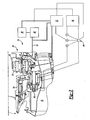
- FIG. 1 is a schematic view of a portion of a turbofan engine 10.
- the turbofan engine 10 includes a compressor section 12 with compressor blades 14 that rotate about an axis A driven by a turbine shaft 16.
- a fan section 18 is supported on a fan shaft 20 and driven by the turbine shaft 16 using a planetary gear set 22.
- a fan drive gear system 26 rotates a fan shaft 20 to drive the fan section 18.
- the fan drive gear system 26 includes a sun gear 30 and a plurality of planetary gears 32 that engage the sun gear 30.
- Journal bearings 34 are located between the planetary gears 32 and support shafts 36 to reduce friction.
- the planetary gears 32 rotate relative to the journal bearings 34.
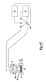
- a primary oil pump 40 pumps oil from an oil supply 38 to lubricate the fan drive gear system 26 as shown in Figure 3 .
- the oil from the primary oil pump 40 communicates along an oil flow path 42 to the journal bearings 34.
- An engine control system 44 senses the status of the engine 10 and controls a switch 46 to manage the oil supply to the journal bearings 34 and a fan braking system 24.
- a person skilled in the art would be able to develop an engine control system 44 capable of monitoring aircraft altitude and status of the engine 10. Using the status of the engine 10 and the altitude of the aircraft, the engine control system 44 determines an appropriate position of the switch 46.
- the switch 46 is a three-way switch.
- the switch 46 When the engine 10 is operating, and the turbine shaft 16 is driving the fan section 18, the switch 46 is "open” (position 1). In this position, the primary oil pump 40 is powered by the engine 10 and provides oil for the journal bearings 34.
- the switch 46 is located between the engine control system 44 and a generator 48 for powering a secondary oil pump 50.
- the switch 46 moves to position 2, a position that activates the secondary oil pump 50.
- the secondary oil pump 50 provides oil to the journal bearings 34.
- the oil prevents the fan section 18 from seizing as the fan section 18 windmills when the engine 10 is shut-down, such as when an engine 10 shuts down when the aircraft is moving through the air.
- the generator 48 provides power to drive the secondary oil pump 50, which communicates oil from the oil supply 38 through the oil flow path 42.
- the secondary oil pump 50 may utilize oil supply lines separate from the primary oil pump 40.
- the engine control system 44 can be set to move the switch 46 to position 2 to activate the secondary oil pump 50 when the engine 10 is cycled on and off. In this manner, the secondary oil pump 50 will be ready for use if needed when the aircraft is in flight.
- Various sources of air flowing though the fan section 18 cause windmilling in an unpowered engine 10. For example, wind moving though the fan section 18 when the aircraft is at a ground altitude may cause the fan section 18 to windmill. If the engine 10 is shut down and the engine control system 44 senses that the aircraft is at a ground altitude, the switch 46 may move to position that brakes the fan shaft 20 by inhibiting rotation of the fan section 18. In this example, the engine control system 44 moves the switch 46 to a position 3, a position that shorts the generator 48.
- the generator 48 is connected to the fan drive gear system 26 through a spur gear 54. Because the generator 48 is connected to the fan drive gear system 26, the fan section 18 must overcome the torque of the generator 48 to rotate. In this manner, the generator 48 brakes the fan section 18, and prevents wind moving though the engine 10 from moving the fan section 18. A person skilled in the art would be able to position the generator 48 to achieve this result.
- Figure 4A illustrates an end view of an example embodiment for braking the generator shaft 62 using a spring brake 60 and a solenoid 39.
- the spring brake 60 provides braking power to the fan section 18 and may be used if the generator 48 alone is unable to brake the fan section 18.
- Figure 4B illustrates a cross section of the spring brake 60 and the solenoid 39 mounted to the generator shaft 62.
- the spring brake 60 mounts around a generator shaft 62 and is shown in an unbraked position.
- Energizing a coil 66 within the solenoid 39 creates a magnetic field that urges a wedge lever 63 toward the center of the coil 66.
- the wedge lever 63 includes angled faces 67, as shown in the top view of Figure 4C .
- the angled faces 67 abut the brake pad arms 64, and move the upper portion of the brake pad arms 64 toward each other as the wedge lever 63 is urged toward the center of the coil 66. Moving the brake pad arms 64 toward each other compresses a spring 68, and causes lower portions of the brake pad arms 64 to move away from the generator shaft 62 pivoting about points 65.
- the engine control system 44 powers the solenoid 39 to maintain the brake pad arms 64 in a released position by urging the wedge lever 63 toward the center of the coil 66.
- the solenoid 39 receives power from the engine control system 44 when the switch 46 is in position to operate the primary oil pump 40 (position 1) or the secondary oil pump 50 (position 2).
- position 3 When the switch 46 moves to position that shorts the generator 48 (position 3), such as when the engine 10 is not powered and on the ground, the solenoid 39 no longer receives power.
- the solenoid 39 does not urge the wedge lever 63, and the spring 68 forces the brake pad arms 64 to rotate about points 65 to clamp the brake pad arms 64 to the generator shaft 62.
- the spring 68 causes the brake pad arms 64 to apply a consistent force to the generator shaft 62, even when the brake pad arms 64 are worn. For example, repeated application of the brake pad arms 64 may cause wear on the brake liners (not shown) of the brake pad arms 64.
- the spring 68 ensures consistent braking force on the generator shaft 62 even if the liners are worn.
- the generator shaft 62 is connected to the fan drive gear system 26 through the spur gear 54.
- the spring brake 60 prevents rotation of fan section 18.
Landscapes
- Engineering & Computer Science (AREA)
- Mechanical Engineering (AREA)
- General Engineering & Computer Science (AREA)
- Chemical & Material Sciences (AREA)
- Combustion & Propulsion (AREA)
- Wind Motors (AREA)
- Connection Of Motors, Electrical Generators, Mechanical Devices, And The Like (AREA)
Description
- This invention relates to an arrangement for protecting journal bearings of the fan drive systems for turbofan engines by preventing undesired rotation and supplying oil to the journal bearings during rotation.
- Turbofan engines include fan sections driven by planetary gear systems. Journal bearings in the systems reduce friction between planetary gears and corresponding support shafts. An oil system supplies oil to lubricate each of the journal bearings. An oil pump maintains pressure within the oil system to ensure each of the journal bearings receives an adequate supply of oil.
- Turbofan engines may be used to propel a multi-engine aircraft. In such an aircraft, one of the turbofan engines may shut-down during flight if a fault condition occurs. The oil pump also shuts down when the turbofan engine is not operating. Although the turbofan engine is shut down, airflow through the moving engine may continue to rotate (i.e., windmill) the fan section of the turbofan engine. Without some oil supply, the journal bearings may seize and harm the turbofan engine or prevent operation of the turbofan engine. Preventing windmilling while the aircraft is in the air causes drag as the stationary fan section impedes airflow through the turbofan engine.
- When the aircraft is on the ground, airflow through the turbofan engine may cause the fan section to windmill. Without some oil supply while windmilling, the journal bearings may seize and harm the turbofan engine.
- Accordingly, it is desirable to provide an arrangement for lubricating journal bearings when the fan section is windmilling during flight, and to prevent the fan section from windmilling when an aircraft is not in flight.
- A turbofan engine having the features of the preamble of claim 1 is disclosed in
US-A-4651521 . - According to the invention there is provided a turbofan engine as set forth in claim 1.
- A disclosed embodiment provides an arrangement for preventing undesired rotation of the fan section of a turbofan engine and for supplying oil to the journal bearings during rotation of the fan section as a result of windmilling.
- During engine operation, a fan section for a turbofan engine is driven by a fan drive system that includes a planetary gear system. An oil supply system supplies oil to lubricate the planetary gear system. When the engine is not operating, wind passing over the fan can cause the fan to rotate (i.e., windmill) even though the fan is not being driven by the fan drive system.
- The disclosed engine includes a three-way switch controlled by an engine control system. The engine control system senses the engine status and the altitude of the aircraft to determine the desired switch position. When the engine is operating and the fan is being driven the switch maintains an "open" position. The oil supply system includes a primary oil pump, which provides oil from an oil supply during driven operation of the fan.
- The switch is located between the engine control system and a generator for operating a secondary oil pump. When the engine control system senses an engine shut-down during flight, the switch moves to activate the generator and power the secondary oil pump. The secondary oil pump supplies oil that protects the journal bearings if the fan section begins to windmill.
- If the engine is shut down and the engine control system senses that the aircraft is on the ground, the switch is set to apply a brake to prevent rotation of the fan. Specifically, the engine control system moves the switch to short the generator, and to provide a dynamic brake. Because the generator is connected to the fan drive gear system this creates drag on the fan and prevents the fan from rotating.
- A spring brake can also be mounted around the rotor shaft. A solenoid, receiving power from the engine control system, maintains the brake in a released position. When the switch moves to the brake application position, the solenoid no longer receives power and the brake is released which clamps the rotor shaft to prevent rotation.
- These and other features of the present invention can be best understood from the following specification and drawings, the following of which is a brief description.
-
-
Figure 1 is a schematic view of a portion of an example turbofan engine; -
Figure 2 illustrates an example gear system; -
Figure 3 schematically illustrates a fan drive for a fan system of the example turbofan engine; -
Figure 4A illustrates an example rotor brake; -
Figure 4B shows another view of theFigure 4A brake; -
Figure 4C shows yet another view of theFigure 4A brake. -
Figure 1 is a schematic view of a portion of aturbofan engine 10. Theturbofan engine 10 includes acompressor section 12 withcompressor blades 14 that rotate about an axis A driven by aturbine shaft 16. Afan section 18 is supported on afan shaft 20 and driven by theturbine shaft 16 using aplanetary gear set 22. - Referring now to
Figure 2 , a fandrive gear system 26 rotates afan shaft 20 to drive thefan section 18. The fandrive gear system 26 includes asun gear 30 and a plurality ofplanetary gears 32 that engage thesun gear 30.Journal bearings 34 are located between theplanetary gears 32 and supportshafts 36 to reduce friction. Theplanetary gears 32 rotate relative to thejournal bearings 34. - When the
engine 10 is running, aprimary oil pump 40 pumps oil from anoil supply 38 to lubricate the fandrive gear system 26 as shown inFigure 3 . The oil from theprimary oil pump 40 communicates along anoil flow path 42 to thejournal bearings 34. - An
engine control system 44 senses the status of theengine 10 and controls aswitch 46 to manage the oil supply to thejournal bearings 34 and afan braking system 24. A person skilled in the art would be able to develop anengine control system 44 capable of monitoring aircraft altitude and status of theengine 10. Using the status of theengine 10 and the altitude of the aircraft, theengine control system 44 determines an appropriate position of theswitch 46. In one example, theswitch 46 is a three-way switch. - When the
engine 10 is operating, and theturbine shaft 16 is driving thefan section 18, theswitch 46 is "open" (position 1). In this position, theprimary oil pump 40 is powered by theengine 10 and provides oil for thejournal bearings 34. - The
switch 46 is located between theengine control system 44 and agenerator 48 for powering asecondary oil pump 50. When theengine control system 44 senses shut-down of theengine 10 and the aircraft is at a flight altitude, theswitch 46 moves to position 2, a position that activates thesecondary oil pump 50. In this position, thesecondary oil pump 50 provides oil to thejournal bearings 34. The oil prevents thefan section 18 from seizing as thefan section 18 windmills when theengine 10 is shut-down, such as when anengine 10 shuts down when the aircraft is moving through the air. Thegenerator 48 provides power to drive thesecondary oil pump 50, which communicates oil from theoil supply 38 through theoil flow path 42. Alternatively, thesecondary oil pump 50 may utilize oil supply lines separate from theprimary oil pump 40. - The
engine control system 44 can be set to move theswitch 46 to position 2 to activate thesecondary oil pump 50 when theengine 10 is cycled on and off. In this manner, thesecondary oil pump 50 will be ready for use if needed when the aircraft is in flight. - Various sources of air flowing though the
fan section 18 cause windmilling in anunpowered engine 10. For example, wind moving though thefan section 18 when the aircraft is at a ground altitude may cause thefan section 18 to windmill. If theengine 10 is shut down and theengine control system 44 senses that the aircraft is at a ground altitude, theswitch 46 may move to position that brakes thefan shaft 20 by inhibiting rotation of thefan section 18. In this example, theengine control system 44 moves theswitch 46 to aposition 3, a position that shorts thegenerator 48. Thegenerator 48 is connected to the fandrive gear system 26 through aspur gear 54. Because thegenerator 48 is connected to the fandrive gear system 26, thefan section 18 must overcome the torque of thegenerator 48 to rotate. In this manner, thegenerator 48 brakes thefan section 18, and prevents wind moving though theengine 10 from moving thefan section 18. A person skilled in the art would be able to position thegenerator 48 to achieve this result. - In some situations, such a very strong winds, the
generator 48 alone is not enough to brake thefan section 18.Figure 4A illustrates an end view of an example embodiment for braking thegenerator shaft 62 using aspring brake 60 and asolenoid 39. Thespring brake 60 provides braking power to thefan section 18 and may be used if thegenerator 48 alone is unable to brake thefan section 18. -
Figure 4B illustrates a cross section of thespring brake 60 and thesolenoid 39 mounted to thegenerator shaft 62. In this example, thespring brake 60 mounts around agenerator shaft 62 and is shown in an unbraked position. Energizing acoil 66 within thesolenoid 39 creates a magnetic field that urges awedge lever 63 toward the center of thecoil 66. Thewedge lever 63 includes angled faces 67, as shown in the top view ofFigure 4C . The angled faces 67 abut thebrake pad arms 64, and move the upper portion of thebrake pad arms 64 toward each other as thewedge lever 63 is urged toward the center of thecoil 66. Moving thebrake pad arms 64 toward each other compresses aspring 68, and causes lower portions of thebrake pad arms 64 to move away from thegenerator shaft 62 pivoting aboutpoints 65. - The
engine control system 44 powers thesolenoid 39 to maintain thebrake pad arms 64 in a released position by urging thewedge lever 63 toward the center of thecoil 66. Thesolenoid 39 receives power from theengine control system 44 when theswitch 46 is in position to operate the primary oil pump 40 (position 1) or the secondary oil pump 50 (position 2). When theswitch 46 moves to position that shorts the generator 48 (position 3), such as when theengine 10 is not powered and on the ground, thesolenoid 39 no longer receives power. As a result, thesolenoid 39 does not urge thewedge lever 63, and thespring 68 forces thebrake pad arms 64 to rotate aboutpoints 65 to clamp thebrake pad arms 64 to thegenerator shaft 62. Thespring 68 causes thebrake pad arms 64 to apply a consistent force to thegenerator shaft 62, even when thebrake pad arms 64 are worn. For example, repeated application of thebrake pad arms 64 may cause wear on the brake liners (not shown) of thebrake pad arms 64. Thespring 68 ensures consistent braking force on thegenerator shaft 62 even if the liners are worn. - As described in the above embodiment, the
generator shaft 62 is connected to the fandrive gear system 26 through thespur gear 54. Thus, preventing rotation of thegenerator shaft 62 using thespring brake 60 prevents rotation offan section 18. - Although a preferred embodiment of this invention has been disclosed, a worker of ordinary skill in this art may recognize that certain modifications would come within the scope of this invention. For that reason, the following claims should be studied to determine the true scope of coverage available for this invention.
Claims (11)
- A turbofan engine (10), comprising:a fan section (18);a planetary gear system (26) for driving said fan section (18); anda plurality of journal bearings (34) associated with said planetary gear system (26); characterised by further comprising:a switch (46) for selectively supplying oil to said plurality of journal bearings (34), said switch (46) having a position for supplying oil from a primary supply during a driven gear operation and a position for supplying oil from a secondary supply during a windmilling gear operation.
- The turbofan engine of claim 1, including an engine control system (44) for sensing when said engine (10) is operating and for selectively changing the position of said switch.
- The turbofan engine of claim 1 or 2, including an engine control system (44) for sensing an altitude and for selectively changing the position of said switch (46).
- The turbofan engine of any preceding claim, wherein a generator (48) powers said secondary supply.
- The turbofan engine of any preceding claim, wherein a common oil source (38) supplies oil to said primary supply and said secondary supply.
- The turbofan engine of claim 1:wherein said primary supply supplies oil to said plurality of journal bearings (34) during driven gear operation and said secondary supply supplies oil to said plurality of journal bearings (34) during windmilling gear operation; and further comprising a brake (48; 60) to prevent rotation of said fan section (18), said switch (46) selectively applying said brake (48; 60).
- The turbofan engine of claim 6, wherein said primary supply is chosen when said engine (10) is driven, said secondary supply is chosen when said engine (10) is shut down and at an elevated altitude, and said brake (48; 60) is chosen when said engine (10) is shut down and at a ground level altitude.
- The turbofan engine of claim 7, including an engine control system (44) for sensing an altitude and whether said engine (10) is operating.
- The turbofan engine of claim 6, 7 or 8, wherein said secondary supply includes a secondary pump (50) and a secondary supply line in communication with said plurality of journal bearings (34).
- The turbofan engine of any of claims 6 to 9, wherein said brake includes a generator (48) that is shorted to provide a dynamic brake.
- The turbofan engine of any of claims 6 to 10, wherein said brake includes a spring loaded brake (60) that includes a solenoid (39) for selectively applying a clamping brake to a rotatable portion of said fan section (18).
Applications Claiming Priority (1)
| Application Number | Priority Date | Filing Date | Title |
|---|---|---|---|
| US11/552,750 US7849668B2 (en) | 2006-10-25 | 2006-10-25 | Rotor brake and windmilling lubrication system for geared turbofan engine |
Publications (3)
| Publication Number | Publication Date |
|---|---|
| EP1918564A2 EP1918564A2 (en) | 2008-05-07 |
| EP1918564A3 EP1918564A3 (en) | 2011-11-30 |
| EP1918564B1 true EP1918564B1 (en) | 2013-02-27 |
Family
ID=38969800
Family Applications (1)
| Application Number | Title | Priority Date | Filing Date |
|---|---|---|---|
| EP07254177A Active EP1918564B1 (en) | 2006-10-25 | 2007-10-22 | Rotor brake and windmilling lubrication system for geared turbofan engine |
Country Status (3)
| Country | Link |
|---|---|
| US (1) | US7849668B2 (en) |
| EP (1) | EP1918564B1 (en) |
| JP (1) | JP4717046B2 (en) |
Cited By (1)
| Publication number | Priority date | Publication date | Assignee | Title |
|---|---|---|---|---|
| CN106255813A (en) * | 2014-04-29 | 2016-12-21 | 斯奈克玛 | There is the aircraft turbine engine of the machine power output of improvement |
Families Citing this family (56)
| Publication number | Priority date | Publication date | Assignee | Title |
|---|---|---|---|---|
| US8113317B2 (en) * | 2007-07-06 | 2012-02-14 | Honeywell International Inc. | Electric motor driven lubrication pump control system and method that accomodates turbomachine windmill operation |
| US8511055B2 (en) * | 2009-05-22 | 2013-08-20 | United Technologies Corporation | Apparatus and method for providing damper liquid in a gas turbine |
| US8398517B2 (en) * | 2009-06-10 | 2013-03-19 | United Technologies Corporation | Journal bearing with single unit jumper tube and filter |
| US20110004388A1 (en) * | 2009-07-01 | 2011-01-06 | United Technologies Corporation | Turbofan temperature control with variable area nozzle |
| US8425372B2 (en) | 2010-07-14 | 2013-04-23 | Hamilton Sundstrand Corporation | Geared turbofan emergency power |
| US8978352B2 (en) | 2011-10-21 | 2015-03-17 | United Technologies Corporation | Apparatus and method for operating a gas turbine engine during windmilling |
| US8956106B2 (en) * | 2011-12-20 | 2015-02-17 | General Electric Company | Adaptive eductor system |
| US9970352B2 (en) | 2012-01-27 | 2018-05-15 | United Technologies Corporation | Turbomachine fan clutch |
| US9410427B2 (en) | 2012-06-05 | 2016-08-09 | United Technologies Corporation | Compressor power and torque transmitting hub |
| GB201219544D0 (en) | 2012-10-31 | 2012-12-12 | Rolls Royce Deutschland | Geared compressor for gas turbine engine |
| WO2014112977A1 (en) * | 2013-01-15 | 2014-07-24 | United Technologies Corporation | Fluid collection gutter for a geared turbine engine |
| US9316159B2 (en) * | 2013-01-30 | 2016-04-19 | Pratt & Whitney Canada Corp. | Gas turbine engine with transmission |
| US10208624B2 (en) | 2013-02-26 | 2019-02-19 | United Technologies Corporation | Lubrication of journal bearing during clockwise and counter-clockwise rotation |
| WO2014133713A1 (en) | 2013-02-26 | 2014-09-04 | United Technologies Corporation | Turbomachine fan clutch |
| WO2014137571A1 (en) | 2013-03-04 | 2014-09-12 | United Technologies Corporation | Fan drive gear system spline oil lubrication scheme |
| US9752500B2 (en) | 2013-03-14 | 2017-09-05 | Pratt & Whitney Canada Corp. | Gas turbine engine with transmission and method of adjusting rotational speed |
| US8702373B1 (en) | 2013-07-15 | 2014-04-22 | United Technologies Corporation | Lubrication of journal bearing during clockwise and counter-clockwise rotation |
| US10167873B2 (en) | 2013-09-19 | 2019-01-01 | United Technologies Corporation | Dual direction windmill pump for geared turbofan engine |
| EP3063387B8 (en) * | 2013-11-01 | 2021-04-14 | Raytheon Technologies Corporation | Auxiliary oil pump for gas turbine engine gear reduction |
| US9915164B2 (en) * | 2014-05-20 | 2018-03-13 | United Technologies Corporation | Geared turbofan with high speed generator |
| US10107157B2 (en) | 2014-05-28 | 2018-10-23 | United Technologies Corporation | Gas turbine engine lubrication system |
| FR3026774B1 (en) * | 2014-10-07 | 2020-07-17 | Safran Aircraft Engines | TURBOMACHINE COMPRISING A BLOWER ROTOR BRAKING DEVICE. |
| CN104326088B (en) * | 2014-11-05 | 2016-08-24 | 沈阳黎明航空发动机(集团)有限责任公司 | A kind of aero-engine band turns the oil sealing method of oil seal system |
| FR3034140B1 (en) * | 2015-03-26 | 2018-09-07 | Safran Aircraft Engines | AIRCRAFT TURBOMACHINE WITH PLANETARY OR EPICYCLOIDAL REDUCER |
| US10145276B2 (en) | 2015-06-23 | 2018-12-04 | United Technologies Corporation | Lubricant valve monitoring method and assembly |
| US10107135B2 (en) * | 2015-10-26 | 2018-10-23 | United Technologies Corporation | Gas turbine engine with gearbox health features |
| ITUB20156062A1 (en) | 2015-12-01 | 2017-06-01 | Gen Electric | HOUSING FOR USE IN A MOTOR-DRIVEN ENGINE AND WASHING PROCESS OF FLUID FROM IT. |
| US10316856B2 (en) * | 2015-12-01 | 2019-06-11 | General Electric Company | Casing for use in a turbofan engine and method of scavenging fluid therefrom |
| US10634053B2 (en) | 2015-12-21 | 2020-04-28 | United Technologies Corporation | Electric windmill pump for gearbox durability |
| US10287977B2 (en) | 2016-02-16 | 2019-05-14 | General Electric Company | Inline propeller gearbox brake |
| US10526913B2 (en) * | 2016-04-04 | 2020-01-07 | United Technologies Corporation | Anti-windmilling system for a gas turbine engine |
| US10801413B2 (en) * | 2016-04-04 | 2020-10-13 | Raytheon Technologies Corporation | Electromagnetic anti-windmilling system |
| US10337349B2 (en) * | 2016-04-27 | 2019-07-02 | United Technologies Corporation | Anti-windmilling system for a gas turbine engine |
| US10072582B2 (en) | 2016-04-28 | 2018-09-11 | General Electric Company | Integral offset oil tank for inline accessory gearbox |
| US10737801B2 (en) | 2016-10-31 | 2020-08-11 | Rolls-Royce Corporation | Fan module with rotatable vane ring power system |
| GB201804506D0 (en) * | 2018-03-21 | 2018-05-02 | Rolls Royce Plc | Oil system |
| FR3083266B1 (en) * | 2018-06-29 | 2020-10-02 | Safran Aircraft Engines | AIRCRAFT TURBOMACHINE ASSEMBLY INCLUDING AN IMPROVED BLOWER DRIVE REDUCER LUBRICATION SYSTEM IN THE EVENT OF BLOWER AUTOTATION |
| FR3086325B1 (en) * | 2018-09-24 | 2020-11-20 | Safran Aircraft Engines | AUXILIARY OIL TANK FOR AN AIRCRAFT TURBOMACHINE |
| CN109578143B (en) * | 2018-12-10 | 2020-02-04 | 中国航发南方工业有限公司 | Transmission box oil pumping device |
| US11745863B2 (en) | 2019-03-05 | 2023-09-05 | Pratt & Whitney Canada Corp. | Method and system for engine windmilling control |
| FR3108945B1 (en) * | 2020-04-03 | 2022-11-11 | Safran Aircraft Engines | TURBOMACHINE MODULE EQUIPPED WITH AN ELECTRIC MACHINE |
| FR3108951B1 (en) * | 2020-04-03 | 2022-07-15 | Safran Aircraft Engines | GEARBOX LUBRICATION BY BUBBLING |
| FR3111671B1 (en) * | 2020-06-19 | 2022-05-20 | Safran Aircraft Engines | AIRCRAFT TURBOMACHINE COMPRISING A ROTATIONAL BRAKING SYSTEM OF A ROTOR FOR LUBRICATION OF A REDUCER DRIVING A FAN |
| US12028009B2 (en) * | 2020-09-20 | 2024-07-02 | The Boeing Company | Protection system for aircraft electric propulsion motor and motor controller |
| DE102021109637A1 (en) | 2021-04-16 | 2022-10-20 | Rolls-Royce Deutschland Ltd & Co Kg | Planetary gear for a gas turbine engine |
| FR3126016A1 (en) * | 2021-08-04 | 2023-02-10 | Safran Helicopter Engines | Turboprop capable of providing an emergency wind turbine function and aircraft comprising such a turboprop |
| US12320418B2 (en) * | 2022-06-22 | 2025-06-03 | General Electric Company | Gearbox assembly with lubricant extraction volume ratio |
| US12326115B2 (en) * | 2022-06-22 | 2025-06-10 | General Electric Company | Gearbox assembly with lubricant extraction volume ratio |
| US12368343B2 (en) | 2023-01-30 | 2025-07-22 | Hamilton Sundstrand Corporation | Turbogenerator brakes |
| US12160156B2 (en) | 2023-02-03 | 2024-12-03 | Hamilton Sundstrand Corporation | Permanent magnet generator brakes with dual wedges |
| US12276333B2 (en) * | 2023-06-21 | 2025-04-15 | General Electric Company | Gearbox assembly lubrication system for a turbine engine |
| US20250020070A1 (en) * | 2023-07-12 | 2025-01-16 | General Electric Company | Lubrication system for a turbine engine |
| US12320261B2 (en) * | 2023-07-18 | 2025-06-03 | General Electric Company | Gas turbine engine having a hydraulic fan brake |
| US12228042B1 (en) * | 2023-08-04 | 2025-02-18 | General Electric Company | Lubrication system for a turbine engine |
| CN119801728A (en) * | 2023-10-10 | 2025-04-11 | 通用电气阿维奥有限责任公司 | Lubrication systems for turbine engines |
| CN119801729A (en) * | 2023-10-10 | 2025-04-11 | 通用电气阿维奥有限责任公司 | Lubrication systems for turbine engines |
Family Cites Families (20)
| Publication number | Priority date | Publication date | Assignee | Title |
|---|---|---|---|---|
| US3792586A (en) * | 1973-01-22 | 1974-02-19 | Avco Corp | Bearing assembly systems |
| US4153141A (en) | 1977-06-20 | 1979-05-08 | General Electric Company | Auxiliary oil supply system |
| US4195717A (en) * | 1977-12-27 | 1980-04-01 | General Motors Corporation | Clutch and brake mechanism |
| US4284174A (en) | 1979-04-18 | 1981-08-18 | Avco Corporation | Emergency oil/mist system |
| US4651521A (en) * | 1985-11-21 | 1987-03-24 | Avco Corporation | Convertible turbo-fan, turbo-shaft aircraft propulsion system |
| US4717000A (en) * | 1986-08-05 | 1988-01-05 | Avco Corporation | Integrated emergency lubrication system |
| US4858427A (en) * | 1988-08-08 | 1989-08-22 | General Motors Corporation | Secondary oil system for gas turbine engine |
| US5046306A (en) * | 1990-07-23 | 1991-09-10 | General Motors Corporation | Secondary oil system |
| US5282719A (en) * | 1991-05-13 | 1994-02-01 | Alliedsignal Inc. | Quad mode fan pitch actuation system for a gas turbine engine |
| US5466198A (en) * | 1993-06-11 | 1995-11-14 | United Technologies Corporation | Geared drive system for a bladed propulsor |
| EP1130221A1 (en) * | 2000-02-14 | 2001-09-05 | Techspace Aero S.A. | Method and device for aeronautic engine lubrication |
| US6312215B1 (en) * | 2000-02-15 | 2001-11-06 | United Technologies Corporation | Turbine engine windmilling brake |
| FR2826052B1 (en) * | 2001-06-19 | 2003-12-19 | Snecma Moteurs | RELIEF DEVICE FOR THE IGNITION OF A SELF-ROTATING TURBO-JET |
| US7021042B2 (en) * | 2002-12-13 | 2006-04-04 | United Technologies Corporation | Geartrain coupling for a turbofan engine |
| US7387189B2 (en) * | 2003-08-14 | 2008-06-17 | United Technologies Corp. | Emergency lubrication system |
| US7118336B2 (en) * | 2003-12-19 | 2006-10-10 | Pratt & Whitney Canada Corp. | Pressurized oil supply for propeller engine system |
| US7225607B2 (en) | 2004-08-27 | 2007-06-05 | Pratt & Whitney Canada Corp. | Gas turbine braking apparatus and method |
| US8267826B2 (en) * | 2005-03-15 | 2012-09-18 | United Technologies Corporation | Uninterruptible oil supply in planetary system |
| US7571597B2 (en) * | 2006-01-25 | 2009-08-11 | Honeywell International Inc. | Airframe mounted motor driven lubrication pump control system and method |
| US7662059B2 (en) * | 2006-10-18 | 2010-02-16 | United Technologies Corporation | Lubrication of windmilling journal bearings |
-
2006
- 2006-10-25 US US11/552,750 patent/US7849668B2/en active Active
-
2007
- 2007-10-18 JP JP2007270827A patent/JP4717046B2/en active Active
- 2007-10-22 EP EP07254177A patent/EP1918564B1/en active Active
Cited By (2)
| Publication number | Priority date | Publication date | Assignee | Title |
|---|---|---|---|---|
| CN106255813A (en) * | 2014-04-29 | 2016-12-21 | 斯奈克玛 | There is the aircraft turbine engine of the machine power output of improvement |
| CN106255813B (en) * | 2014-04-29 | 2019-05-07 | 斯奈克玛 | Aircraft turbine engine with the output of improved machine power |
Also Published As
| Publication number | Publication date |
|---|---|
| US20080098712A1 (en) | 2008-05-01 |
| EP1918564A2 (en) | 2008-05-07 |
| JP4717046B2 (en) | 2011-07-06 |
| JP2008106746A (en) | 2008-05-08 |
| EP1918564A3 (en) | 2011-11-30 |
| US7849668B2 (en) | 2010-12-14 |
Similar Documents
| Publication | Publication Date | Title |
|---|---|---|
| EP1918564B1 (en) | Rotor brake and windmilling lubrication system for geared turbofan engine | |
| EP1918550B1 (en) | Lubrication of windmilling journal bearing | |
| US11674413B2 (en) | Gas turbine engine with gearbox health features | |
| US8113317B2 (en) | Electric motor driven lubrication pump control system and method that accomodates turbomachine windmill operation | |
| EP1619370B1 (en) | Gas turbine engine assembly | |
| EP2224120B1 (en) | Auxiliary lubricating pump for turbofan drive gear system | |
| US6428274B1 (en) | Drive mechanism for adjusting the rotor blades of wind power installations | |
| EP3779148B1 (en) | Lubrication of journal bearing during clockwise and counter-clockwise rotation | |
| US20060137355A1 (en) | Fan driven emergency generator | |
| EP2407644B1 (en) | Geared turbofan | |
| EP3099910B1 (en) | Turbocharger system | |
| US8201662B2 (en) | Electric motor driven lubrication pump control system and method for turbomachine windmill operation | |
| CA2549748A1 (en) | Pressurized oil supply for propeller engine system | |
| US10837312B2 (en) | System for braking a low pressure spool in a gas turbine engine | |
| EP2960468B1 (en) | Geared turbofan engine with low pressure environmental control system for aircraft | |
| CN1833095A (en) | Method of braking a turbine engine rotor and a rotating device for driving a turbine engine rotor | |
| CN101918676B (en) | A gas driven rotation motor, a tool provided with a gas driven rotation motor and a method for regulating the rotation speed of a gas driven rotation motor | |
| EP3045697B1 (en) | Cooling air supply control system for air cycle machine | |
| CN118043541A (en) | Turbine engine including oil supply system | |
| WO2024028553A1 (en) | Turboprop capable of providing an emergency wind turbine function and method of implementation | |
| RU2330171C2 (en) | Enhanced dual-flow turbo jet engine | |
| CA2665727A1 (en) | Electric motor driven lubrication pump control system and method for turbomachine windmill operation | |
| JPH1089230A (en) | Variable pitch propeller drive |
Legal Events
| Date | Code | Title | Description |
|---|---|---|---|
| PUAI | Public reference made under article 153(3) epc to a published international application that has entered the european phase |
Free format text: ORIGINAL CODE: 0009012 |
|
| AK | Designated contracting states |
Kind code of ref document: A2 Designated state(s): AT BE BG CH CY CZ DE DK EE ES FI FR GB GR HU IE IS IT LI LT LU LV MC MT NL PL PT RO SE SI SK TR |
|
| AX | Request for extension of the european patent |
Extension state: AL BA HR MK RS |
|
| PUAL | Search report despatched |
Free format text: ORIGINAL CODE: 0009013 |
|
| AK | Designated contracting states |
Kind code of ref document: A3 Designated state(s): AT BE BG CH CY CZ DE DK EE ES FI FR GB GR HU IE IS IT LI LT LU LV MC MT NL PL PT RO SE SI SK TR |
|
| AX | Request for extension of the european patent |
Extension state: AL BA HR MK RS |
|
| RIC1 | Information provided on ipc code assigned before grant |
Ipc: F01D 25/18 20060101ALI20111021BHEP Ipc: F02K 3/04 20060101AFI20111021BHEP Ipc: F02C 7/32 20060101ALI20111021BHEP |
|
| 17P | Request for examination filed |
Effective date: 20120529 |
|
| AKX | Designation fees paid |
Designated state(s): DE FR GB IT |
|
| GRAP | Despatch of communication of intention to grant a patent |
Free format text: ORIGINAL CODE: EPIDOSNIGR1 |
|
| GRAS | Grant fee paid |
Free format text: ORIGINAL CODE: EPIDOSNIGR3 |
|
| GRAA | (expected) grant |
Free format text: ORIGINAL CODE: 0009210 |
|
| AK | Designated contracting states |
Kind code of ref document: B1 Designated state(s): DE FR GB IT |
|
| REG | Reference to a national code |
Ref country code: GB Ref legal event code: FG4D |
|
| REG | Reference to a national code |
Ref country code: DE Ref legal event code: R096 Ref document number: 602007028677 Country of ref document: DE Effective date: 20130425 |
|
| PG25 | Lapsed in a contracting state [announced via postgrant information from national office to epo] |
Ref country code: IT Free format text: LAPSE BECAUSE OF FAILURE TO SUBMIT A TRANSLATION OF THE DESCRIPTION OR TO PAY THE FEE WITHIN THE PRESCRIBED TIME-LIMIT Effective date: 20130227 |
|
| PLBE | No opposition filed within time limit |
Free format text: ORIGINAL CODE: 0009261 |
|
| STAA | Information on the status of an ep patent application or granted ep patent |
Free format text: STATUS: NO OPPOSITION FILED WITHIN TIME LIMIT |
|
| 26N | No opposition filed |
Effective date: 20131128 |
|
| REG | Reference to a national code |
Ref country code: DE Ref legal event code: R097 Ref document number: 602007028677 Country of ref document: DE Effective date: 20131128 |
|
| REG | Reference to a national code |
Ref country code: FR Ref legal event code: ST Effective date: 20140630 |
|
| PG25 | Lapsed in a contracting state [announced via postgrant information from national office to epo] |
Ref country code: FR Free format text: LAPSE BECAUSE OF NON-PAYMENT OF DUE FEES Effective date: 20131031 |
|
| REG | Reference to a national code |
Ref country code: DE Ref legal event code: R082 Ref document number: 602007028677 Country of ref document: DE Representative=s name: SCHMITT-NILSON SCHRAUD WAIBEL WOHLFROM PATENTA, DE |
|
| REG | Reference to a national code |
Ref country code: DE Ref legal event code: R082 Ref document number: 602007028677 Country of ref document: DE Representative=s name: SCHMITT-NILSON SCHRAUD WAIBEL WOHLFROM PATENTA, DE Ref country code: DE Ref legal event code: R081 Ref document number: 602007028677 Country of ref document: DE Owner name: UNITED TECHNOLOGIES CORP. (N.D.GES.D. STAATES , US Free format text: FORMER OWNER: UNITED TECHNOLOGIES CORPORATION, HARTFORD, CONN., US |
|
| REG | Reference to a national code |
Ref country code: DE Ref legal event code: R081 Ref document number: 602007028677 Country of ref document: DE Owner name: RAYTHEON TECHNOLOGIES CORPORATION (N.D.GES.D.S, US Free format text: FORMER OWNER: UNITED TECHNOLOGIES CORP. (N.D.GES.D. STAATES DELAWARE), FARMINGTON, CONN., US |
|
| P01 | Opt-out of the competence of the unified patent court (upc) registered |
Effective date: 20230519 |
|
| PGFP | Annual fee paid to national office [announced via postgrant information from national office to epo] |
Ref country code: GB Payment date: 20240919 Year of fee payment: 18 |
|
| PGFP | Annual fee paid to national office [announced via postgrant information from national office to epo] |
Ref country code: DE Payment date: 20240919 Year of fee payment: 18 |