EP1918464B1 - Water outlet apparatus - Google Patents
Water outlet apparatus Download PDFInfo
- Publication number
- EP1918464B1 EP1918464B1 EP20070119601 EP07119601A EP1918464B1 EP 1918464 B1 EP1918464 B1 EP 1918464B1 EP 20070119601 EP20070119601 EP 20070119601 EP 07119601 A EP07119601 A EP 07119601A EP 1918464 B1 EP1918464 B1 EP 1918464B1
- Authority
- EP
- European Patent Office
- Prior art keywords
- water outlet
- wand
- outlet apparatus
- outer part
- hosing
- Prior art date
- Legal status (The legal status is an assumption and is not a legal conclusion. Google has not performed a legal analysis and makes no representation as to the accuracy of the status listed.)
- Active
Links
Images

Classifications
-
- E—FIXED CONSTRUCTIONS
- E03—WATER SUPPLY; SEWERAGE
- E03C—DOMESTIC PLUMBING INSTALLATIONS FOR FRESH WATER OR WASTE WATER; SINKS
- E03C1/00—Domestic plumbing installations for fresh water or waste water; Sinks
- E03C1/02—Plumbing installations for fresh water
- E03C1/04—Water-basin installations specially adapted to wash-basins or baths
- E03C1/0408—Water installations especially for showers
- E03C1/0409—Shower handles
-
- B—PERFORMING OPERATIONS; TRANSPORTING
- B05—SPRAYING OR ATOMISING IN GENERAL; APPLYING FLUENT MATERIALS TO SURFACES, IN GENERAL
- B05B—SPRAYING APPARATUS; ATOMISING APPARATUS; NOZZLES
- B05B1/00—Nozzles, spray heads or other outlets, with or without auxiliary devices such as valves, heating means
- B05B1/14—Nozzles, spray heads or other outlets, with or without auxiliary devices such as valves, heating means with multiple outlet openings; with strainers in or outside the outlet opening
- B05B1/18—Roses; Shower heads
-
- E—FIXED CONSTRUCTIONS
- E03—WATER SUPPLY; SEWERAGE
- E03C—DOMESTIC PLUMBING INSTALLATIONS FOR FRESH WATER OR WASTE WATER; SINKS
- E03C1/00—Domestic plumbing installations for fresh water or waste water; Sinks
- E03C1/02—Plumbing installations for fresh water
- E03C1/04—Water-basin installations specially adapted to wash-basins or baths
- E03C1/0404—Constructional or functional features of the spout
-
- E—FIXED CONSTRUCTIONS
- E03—WATER SUPPLY; SEWERAGE
- E03D—WATER-CLOSETS OR URINALS WITH FLUSHING DEVICES; FLUSHING VALVES THEREFOR
- E03D9/00—Sanitary or other accessories for lavatories ; Devices for cleaning or disinfecting the toilet room or the toilet bowl; Devices for eliminating smells
- E03D9/08—Devices in the bowl producing upwardly-directed sprays; Modifications of the bowl for use with such devices ; Bidets; Combinations of bowls with urinals or bidets; Hot-air or other devices mounted in or on the bowl, urinal or bidet for cleaning or disinfecting
- E03D9/085—Hand-held spray heads for bidet use or for cleaning the bowl
-
- F—MECHANICAL ENGINEERING; LIGHTING; HEATING; WEAPONS; BLASTING
- F16—ENGINEERING ELEMENTS AND UNITS; GENERAL MEASURES FOR PRODUCING AND MAINTAINING EFFECTIVE FUNCTIONING OF MACHINES OR INSTALLATIONS; THERMAL INSULATION IN GENERAL
- F16K—VALVES; TAPS; COCKS; ACTUATING-FLOATS; DEVICES FOR VENTING OR AERATING
- F16K27/00—Construction of housing; Use of materials therefor
- F16K27/04—Construction of housing; Use of materials therefor of sliding valves
- F16K27/044—Construction of housing; Use of materials therefor of sliding valves slide valves with flat obturating members
-
- B—PERFORMING OPERATIONS; TRANSPORTING
- B05—SPRAYING OR ATOMISING IN GENERAL; APPLYING FLUENT MATERIALS TO SURFACES, IN GENERAL
- B05B—SPRAYING APPARATUS; ATOMISING APPARATUS; NOZZLES
- B05B1/00—Nozzles, spray heads or other outlets, with or without auxiliary devices such as valves, heating means
- B05B1/30—Nozzles, spray heads or other outlets, with or without auxiliary devices such as valves, heating means designed to control volume of flow, e.g. with adjustable passages
- B05B1/3026—Gate valves; Sliding valves; Cocks
-
- E—FIXED CONSTRUCTIONS
- E03—WATER SUPPLY; SEWERAGE
- E03C—DOMESTIC PLUMBING INSTALLATIONS FOR FRESH WATER OR WASTE WATER; SINKS
- E03C1/00—Domestic plumbing installations for fresh water or waste water; Sinks
- E03C1/02—Plumbing installations for fresh water
- E03C1/04—Water-basin installations specially adapted to wash-basins or baths
- E03C2001/0415—Water-basin installations specially adapted to wash-basins or baths having an extendable water outlet
-
- Y—GENERAL TAGGING OF NEW TECHNOLOGICAL DEVELOPMENTS; GENERAL TAGGING OF CROSS-SECTIONAL TECHNOLOGIES SPANNING OVER SEVERAL SECTIONS OF THE IPC; TECHNICAL SUBJECTS COVERED BY FORMER USPC CROSS-REFERENCE ART COLLECTIONS [XRACs] AND DIGESTS
- Y10—TECHNICAL SUBJECTS COVERED BY FORMER USPC
- Y10T—TECHNICAL SUBJECTS COVERED BY FORMER US CLASSIFICATION
- Y10T137/00—Fluid handling
- Y10T137/8593—Systems
- Y10T137/86493—Multi-way valve unit
- Y10T137/86815—Multiple inlet with single outlet
- Y10T137/86823—Rotary valve
Definitions
- This invention relates to a water outlet apparatus for personal use, primarily but not necessarily, in ablutions.
- a known water outlet apparatus is e.g. disclosed in NL-A-7214379 , showing in particular a hand-held tubular wand, a hosing, the wand comprising an outer part and an inner part, the outer part being provided with water outlet means, and a shut-off valve being housed in an inner end of the outer part. Further development of such a known apparatus is needed.
- the present Invention Is a water outlet apparatus comprising a hand-held tubular wand and a hosing, the hand-held tubular wand comprising an outer part and an inner part, one of said parts being co-axially rotatable with respect to the other part; the inner part of the wand being connected to one end of the hosing and an outer part of the wand being provided with water outlet means at or towards an outer end of the outer part; and a mixing/shut-off valve being housed in an inner end of the outer part of the wand oriented toward the inner part of the wand, the hosing being for separate delivery, through the inner part, of two types of water to the valve for mixing; an other end of the hosing being for integration into two separate sources of water, wherein the inner part and the outer part are rotatable relative to one another causing the two types of water to flow and be mixed via the valve to obtain a desired temperature of mixed water.
- the water outlet means is a series of nozzles of the outer part of the wand for use as a shower head.
- the nozzles are preferably arranged radially of the outer part of the wand.
- the water outlet means is a faucet head provided radially of the outer part of the wand.
- the hosing is a flexible concentric pipe, a flexible pipe partitioned to form two passages or two flexible side-by-side pipes linked together or located within an outer covering.
- the mixing/shut-off valve is preferably of a ceramic material.
- the wand is of stainless steel or of a plastics material.
- Each part is beneficially provided with gripping means to enable the parts to be gripped for rotation relative to each other.
- the gripping means may take different forms, for example the nozzles may protrude out from the outer part of the wand and a number of similar protrusions may be provided on the inner part.
- the outer surface of the inner part is shaped to provide a grip, or is interfered with to provide checking or knurling for gripping.
- the inner end of the inner part is desirably tapered In a direction away from the outer part to seat in a ring, or a clip of substantially three quarter circular shape for upward support of the wand.
- a water outlet apparatus comprises a hand-held tubular wand 10 in two co-axial rotatable parts 12, 14 in which at or towards the outer end of an outer part, water outlet means 16 is provided with a mixing/shut-off valve 18 being housed in an inner end thereof for rotation relative thereto.
- An inner part 14 has secured therein one end of a hosing 20 for delivery separately of two types of water, i.e. hot and cold water, to the valve 18 for mixing, the other end of the hosing 20 being for integration into two separate sources of water (not shown).
- This arrangement provides the hand-held wand 10 with water flow, temperature control and shut off.
- the water outlet means 16 is shown as a series of nozzles 22 arranged in a rectangular array radially of the outer part of the wand 10 as shown for use as a shower head.
- the hosing 20 is two flexible side-by-side pipes 24 located within an outer covering, or are linked together by forming or fusing together. Alternatively, the hosing 20 is a flexible concentric pipe (not shown) or a flexible pipe partitioned to form two passages (not shown).
- the mixing/shut-off valve 18 is desirably of a ceramic material but may be of a plastics material. There are O-rings 26 between the valve 18 and its seating in the outer part 12 and between it and the inner part 14. Part of the mixing/shut-off valve is made fast with the inner part.
- the wand 10 is of stainless steel or of a plastics material.
- the plastics material may have a metallised outer finish, such as chrome.
- Each part 12, 14 of the wand 10 is provided with gripping means to enable the parts to be gripped for rotation relative to each other.
- the gripping means may take different forms, for example the nozzles protrude out from the outer part of the wand and a number of similar protrusions (not shown) are provided on the inner part.
- the outer surface of the inner part is shaped to provide a grip (not shown), or is interfered with to provide checking or knurling for gripping (not shown) or recesses in which protrusions of rubber may be inserted (not shown).
- the inner end of the inner part 14 is tapered at 30 in a direction away from the outer part to seat in a ring (not shown), or a clip of substantially three quarter circular shape for support of the wand when in use or out-of-use.
- the water outlet means is shown as a faucet head 28 provided radially of the outer part of the wand 10.
- the wand In use, the wand is removed from its support and the parts are rotated relative to each other to cause the two types of waters to flow and be mixed as required to obtain the necessary temperature mix. After use, the parts are rotated relative to each other to shut off the flow of waters and the wand placed back into its support.
- the marginal zone next to the outer end of the outer part of the wand may be fashioned as a rotatable on/off switch having a jet nozzle through the outer end, a facility being provided to close off the passage of water to the series of nozzles or faucet head on opening of the on/off switch.
- an end fitment 32 is secured over the outer end of rotatable part 12 as shown in Fig. 3 .
- the end fitment 32 is rubberised to prevent damage to any ground/deck surface if the wand 10 is dropped.
- the surface may be the deck of a vessel, e.g. motor boat or motor cruiser or other surface below where the apparatus is fitted.
- the fitment comprises two space circular formations 34, 36 which may be of different diameter as shown, the larger one 34 being attached to the outer end of part 12.
- the formations 34,36 are axially secured together.
- the larger one 34 may also serve to close off the entry to a recessed holder (not shown) for the wand 10.
Landscapes
- Engineering & Computer Science (AREA)
- Public Health (AREA)
- Health & Medical Sciences (AREA)
- Life Sciences & Earth Sciences (AREA)
- Hydrology & Water Resources (AREA)
- Water Supply & Treatment (AREA)
- General Engineering & Computer Science (AREA)
- Molecular Biology (AREA)
- Epidemiology (AREA)
- Mechanical Engineering (AREA)
- Nozzles (AREA)
- Domestic Plumbing Installations (AREA)
- Paper (AREA)
Description
- This invention relates to a water outlet apparatus for personal use, primarily but not necessarily, in ablutions.
- A known water outlet apparatus is e.g. disclosed in
NL-A-7214379 - Accordingly, the present Invention Is a water outlet apparatus comprising
a hand-held tubular wand and a hosing, the hand-held tubular wand comprising an outer part and an inner part, one of said parts being co-axially rotatable with respect to the other part;
the inner part of the wand being connected to one end of the hosing and an outer part of the wand being provided with water outlet means at or towards an outer end of the outer part; and
a mixing/shut-off valve being housed in an inner end of the outer part of the wand oriented toward the inner part of the wand,
the hosing being for separate delivery, through the inner part, of two types of water to the valve for mixing;
an other end of the hosing being for integration into two separate sources of water, wherein the inner part and the outer part are rotatable relative to one another causing the two types of water to flow and be mixed via the valve to obtain a desired temperature of mixed water. - Preferably, the water outlet means is a series of nozzles of the outer part of the wand for use as a shower head. The nozzles are preferably arranged radially of the outer part of the wand. Alternatively, the water outlet means is a faucet head provided radially of the outer part of the wand.
- Preferably also, the hosing is a flexible concentric pipe, a flexible pipe partitioned to form two passages or two flexible side-by-side pipes linked together or located within an outer covering. The mixing/shut-off valve is preferably of a ceramic material.
- Preferably further, the wand is of stainless steel or of a plastics material. Each part is beneficially provided with gripping means to enable the parts to be gripped for rotation relative to each other. The gripping means may take different forms, for example the nozzles may protrude out from the outer part of the wand and a number of similar protrusions may be provided on the inner part. Alternatively, the outer surface of the inner part is shaped to provide a grip, or is interfered with to provide checking or knurling for gripping. The inner end of the inner part is desirably tapered In a direction away from the outer part to seat in a ring, or a clip of substantially three quarter circular shape for upward support of the wand.
- An embodiment of the present invention will now be described, by way of example, with reference to the accompanying drawings, in which:-
-
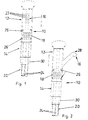
Fig. 1 is a cross-sectional view of a water outlet apparatus according to the present invention showing one form of water outlet means; -
Fig. 2 is a cross-sectional view of the water outlet apparatus showing a second form of water outlet means; and -
Fig. 3 is a cross-sectional view of the water outlet apparatus according to a second modification. - Referring to the drawings, a water outlet apparatus comprises a hand-held
tubular wand 10 in two co-axialrotatable parts valve 18 being housed in an inner end thereof for rotation relative thereto. Aninner part 14 has secured therein one end of ahosing 20 for delivery separately of two types of water, i.e. hot and cold water, to thevalve 18 for mixing, the other end of thehosing 20 being for integration into two separate sources of water (not shown). This arrangement provides the hand-heldwand 10 with water flow, temperature control and shut off. - In
Fig. 1 , the water outlet means 16 is shown as a series ofnozzles 22 arranged in a rectangular array radially of the outer part of thewand 10 as shown for use as a shower head. - The
hosing 20 is two flexible side-by-side pipes 24 located within an outer covering, or are linked together by forming or fusing together. Alternatively, thehosing 20 is a flexible concentric pipe (not shown) or a flexible pipe partitioned to form two passages (not shown). The mixing/shut-offvalve 18 is desirably of a ceramic material but may be of a plastics material. There are O-rings 26 between thevalve 18 and its seating in theouter part 12 and between it and theinner part 14. Part of the mixing/shut-off valve is made fast with the inner part. - The
wand 10 is of stainless steel or of a plastics material. The plastics material may have a metallised outer finish, such as chrome. Eachpart wand 10 is provided with gripping means to enable the parts to be gripped for rotation relative to each other. The gripping means may take different forms, for example the nozzles protrude out from the outer part of the wand and a number of similar protrusions (not shown) are provided on the inner part. Alternatively, the outer surface of the inner part is shaped to provide a grip (not shown), or is interfered with to provide checking or knurling for gripping (not shown) or recesses in which protrusions of rubber may be inserted (not shown). The inner end of theinner part 14 is tapered at 30 in a direction away from the outer part to seat in a ring (not shown), or a clip of substantially three quarter circular shape for support of the wand when in use or out-of-use. - Alternatively in
Fig. 2 , the water outlet means is shown as afaucet head 28 provided radially of the outer part of thewand 10. - In use, the wand is removed from its support and the parts are rotated relative to each other to cause the two types of waters to flow and be mixed as required to obtain the necessary temperature mix. After use, the parts are rotated relative to each other to shut off the flow of waters and the wand placed back into its support.
- In a first modification (not shown), the marginal zone next to the outer end of the outer part of the wand may be fashioned as a rotatable on/off switch having a jet nozzle through the outer end, a facility being provided to close off the passage of water to the series of nozzles or faucet head on opening of the on/off switch.
- In a second modification, an
end fitment 32 is secured over the outer end ofrotatable part 12 as shown inFig. 3 . Theend fitment 32 is rubberised to prevent damage to any ground/deck surface if thewand 10 is dropped. The surface may be the deck of a vessel, e.g. motor boat or motor cruiser or other surface below where the apparatus is fitted. The fitment comprises two spacecircular formations part 12. Theformations wand 10. - Variations and other modifications may be made without departing from the scope of the invention as claimed hereinafter.
Claims (14)
- A water outlet apparatus comprising
a hand-held tubular wand (10) and a hosing (20), the hand-held tubular wand (10) comprising an outer part (12) and an inner part (14), one of said parts (12, 14) being co-axially rotatable with respect to the other part;
the inner part (14) of the wand being connected to one end of the hosing (20) and an outer part (12) of the wand (10) being provided with water outlet means (16) at or towards an outer end of the outer part (12); and
a mixing/shut-off valve (18) being housed in an inner end of the outer part (12) of the wand oriented toward the inner part (14) of the wand,
the hosing (20) being for separate delivery, through the inner part (14), of two types of water to the valve (18) for mixing;
an other end of the hosing (20) being for integration into two separate sources of water, wherein the inner part and the outer part are rotatable relative to one another causing the two types of water to flow and be mixed via the valve to obtain a desired temperature of mixed water. - A water outlet apparatus as claimed in Claim 1, characterised in that the water outlet means (16) is a series of nozzles (22) of the outer part of the wand (10) for use as a shower head.
- A water outlet apparatus as claimed in Claim 2, characterised in that the nozzles (22) are arranged radially of the outer part of the wand (10).
- A water outlet apparatus as claimed in Claim 1, characterised in that the water outlet means (16) is a faucet head (28) provided radially of the outer part of the wand (10).
- A water outlet apparatus as claimed in Claim 1, 2, 3 or 4, characterised in that the hosing (20) is a flexible concentric pipe, a flexible pipe partitioned to form two passages or two flexible side-by-side pipes (24) linked together or located within an outer covering.
- A water outlet apparatus as claimed in any one of the preceding Claims, characterised in that the mixing/shut-off valve (18) is of a ceramic material.
- A water outlet apparatus as claimed in any one of the preceding Claims, characterised in that the wand (10) is of stainless steel or of a plastics material.
- A water outlet apparatus as claimed in any one of the preceding Claims, characterised in that each part (12, 14) of the wand (10) is provided with gripping means to enable the parts to be gripped for rotation relative to each other.
- A water outlet apparatus as claimed in Claim 8, characterised in that the gripping means comprises the nozzles protruding out from the outer part of the wand and a number of similar protrusions are provided on the inner part.
- A water outlet apparatus as claimed in any one of the preceding Claims 1 to 8, characterised in that the outer surface of the inner part (14) is shaped to provide a grip, or is interfered with to provide checking or knurling for gripping.
- A water outlet apparatus as claimed in any one of the preceding Claims, characterised in that the inner end of the inner part (14) is tapered in a direction away from the outer part (12) to seat in a ring, or a clip of substantially three quarter circular shape for upward support of the wand (10).
- A water outlet apparatus as claimed in any one of the preceding Claims, characterised in that an end fitment (32) is secured over the outer end of the rotatable part (12) of the wand (10).
- A water outlet apparatus as claimed in Claim 12, characterised in that the end fitment (32) is rubberised.
- A water outlet apparatus as claimed in Claim 12 or 13, characterised in that the fitment (32) comprises two spaced circular formations (34,36) axially secured.
Applications Claiming Priority (1)
| Application Number | Priority Date | Filing Date | Title |
|---|---|---|---|
| GB0621530A GB0621530D0 (en) | 2006-10-30 | 2006-10-30 | Water outlet apparatus |
Publications (3)
| Publication Number | Publication Date |
|---|---|
| EP1918464A2 EP1918464A2 (en) | 2008-05-07 |
| EP1918464A3 EP1918464A3 (en) | 2010-05-26 |
| EP1918464B1 true EP1918464B1 (en) | 2013-12-04 |
Family
ID=37546182
Family Applications (1)
| Application Number | Title | Priority Date | Filing Date |
|---|---|---|---|
| EP20070119601 Active EP1918464B1 (en) | 2006-10-30 | 2007-10-30 | Water outlet apparatus |
Country Status (7)
| Country | Link |
|---|---|
| US (1) | US7753291B2 (en) |
| EP (1) | EP1918464B1 (en) |
| AU (1) | AU2007231705B2 (en) |
| ES (1) | ES2450216T3 (en) |
| GB (1) | GB0621530D0 (en) |
| NO (1) | NO338261B1 (en) |
| NZ (1) | NZ562931A (en) |
Families Citing this family (5)
| Publication number | Priority date | Publication date | Assignee | Title |
|---|---|---|---|---|
| US8230882B2 (en) * | 2007-02-21 | 2012-07-31 | Neoperl Gmbh | Telescoping water outlet |
| WO2012162120A1 (en) * | 2011-05-20 | 2012-11-29 | Kohler Co. | Shower device |
| US9387495B2 (en) | 2011-05-20 | 2016-07-12 | Kohler Co. | Shower device |
| GB2614758B (en) | 2022-01-18 | 2024-09-04 | Brunswick Corp | Shower systems for use with mixer showers and methods for installing mixer showers |
| IT202200004449U1 (en) | 2022-10-28 | 2024-04-28 | Osculati S R L | Water dispenser with integrated mixer |
Family Cites Families (17)
| Publication number | Priority date | Publication date | Assignee | Title |
|---|---|---|---|---|
| US633069A (en) * | 1898-12-20 | 1899-09-12 | Joseph Busha | Hose-nozzle. |
| US2776168A (en) * | 1954-09-20 | 1957-01-01 | Rufin L Schweda | Extension and telescoping attachment for nozzle of showers |
| BE790705A (en) * | 1971-10-29 | 1973-02-15 | Walker Crosweller & Cy Ltd | TOILET FACILITIES |
| FR2398247A1 (en) * | 1977-07-20 | 1979-02-16 | Guyot Michel | Fibre reinforced plastic tubes with internal longitudinal partitions - for multichannel pipes with high stiffness to weight ratios |
| US4652024A (en) * | 1986-05-12 | 1987-03-24 | Graco Inc. | Telescoping handle and pressure liquid conduit |
| US4785998A (en) * | 1986-06-09 | 1988-11-22 | Toshio Takagi | Water spraying nozzle |
| US4848667A (en) * | 1987-04-30 | 1989-07-18 | Raleigh Equities Ltd. | Water spray nozzle including combined intake nozzle and valve structure |
| DE3914840A1 (en) * | 1989-05-05 | 1990-11-08 | Vorwerk Co Interholding | TELESCOPICOUS GUIDE FOR FLOOR MAINTENANCE EQUIPMENT |
| US5336012A (en) * | 1993-01-11 | 1994-08-09 | Newville Duane H | Flow-through washing and scrubbing brush handle |
| EP1004263A1 (en) * | 1998-11-09 | 2000-05-31 | The Procter & Gamble Company | A telescopic spray arm |
| US6158469A (en) * | 1999-09-23 | 2000-12-12 | Globe Union Industrial Corporation | Spout assembly adapted to be in fluid communication with a faucet |
| US6619570B1 (en) * | 2000-06-14 | 2003-09-16 | Orbit Irrigation Products, Inc. | Telescoping watering wand |
| DE10208190B4 (en) * | 2002-02-20 | 2009-05-20 | Kludi Gmbh & Co. Kg | Shower hose with valve |
| JP4496961B2 (en) * | 2002-09-20 | 2010-07-07 | Toto株式会社 | Shower nozzle |
| US6789751B1 (en) * | 2003-03-25 | 2004-09-14 | Winner Double-H Co., Ltd. | Collapsible handle for a shower head |
| US20080313801A1 (en) * | 2007-06-25 | 2008-12-25 | Thomas Jason Saxon | Telescoping shower for a boat |
| USD588683S1 (en) * | 2007-07-19 | 2009-03-17 | Master Simms Engineering Limited | Spray head holder |
-
2006
- 2006-10-30 GB GB0621530A patent/GB0621530D0/en not_active Ceased
-
2007
- 2007-10-29 US US11/926,461 patent/US7753291B2/en active Active
- 2007-10-29 NO NO20075455A patent/NO338261B1/en not_active IP Right Cessation
- 2007-10-29 NZ NZ562931A patent/NZ562931A/en not_active IP Right Cessation
- 2007-10-30 ES ES07119601T patent/ES2450216T3/en active Active
- 2007-10-30 AU AU2007231705A patent/AU2007231705B2/en not_active Ceased
- 2007-10-30 EP EP20070119601 patent/EP1918464B1/en active Active
Also Published As
| Publication number | Publication date |
|---|---|
| NO20075455L (en) | 2008-05-02 |
| US7753291B2 (en) | 2010-07-13 |
| EP1918464A3 (en) | 2010-05-26 |
| ES2450216T3 (en) | 2014-03-24 |
| GB0621530D0 (en) | 2006-12-06 |
| NO338261B1 (en) | 2016-08-08 |
| EP1918464A2 (en) | 2008-05-07 |
| US20080156888A1 (en) | 2008-07-03 |
| AU2007231705A1 (en) | 2008-05-15 |
| AU2007231705B2 (en) | 2011-04-07 |
| NZ562931A (en) | 2009-03-31 |
Similar Documents
| Publication | Publication Date | Title |
|---|---|---|
| AU774193B2 (en) | In-line basket filter and anti-siphon valve assembly for spray spout and the like | |
| AU2007231705B2 (en) | Water outlet apparatus | |
| EP2896759B1 (en) | Water dispensing device with spray head, particularly for sinks or similar hygienic-sanitary fixtures, with improved manoeuverability | |
| US8870095B2 (en) | Locking pressurized fluid connection | |
| US8876023B2 (en) | Showerhead | |
| AU2018297218B2 (en) | Integrated mixed tap water and conditioned water faucet assembly with pull out sprayer head | |
| US8646476B2 (en) | Integrated kitchen faucet side spray and diverter | |
| JP7161759B2 (en) | Mixing faucet for distributing water | |
| EP2808456A1 (en) | Dislocatable, self-sealable tap | |
| EP2896758B1 (en) | Mixer group with detachable hand-held shower | |
| EP3426407B1 (en) | Spray head | |
| MXPA06001400A (en) | Two-handle faucet design with manifold about faucet handles. | |
| JP4030828B2 (en) | Shower head | |
| US12312780B2 (en) | Fastener for a sanitary faucet, a sanitary faucet having a fastener and a method for securing a sanitary faucet to a support | |
| KR101249814B1 (en) | Shower head | |
| WO2013006914A1 (en) | Hot water tap and system with diversion feature | |
| JP2006169762A (en) | Branch connector | |
| CN118371348A (en) | Shower for bathroom accessories | |
| CA2576401A1 (en) | In-line basket filter and anti-siphon valve assembly for spray spout and the like |
Legal Events
| Date | Code | Title | Description |
|---|---|---|---|
| PUAI | Public reference made under article 153(3) epc to a published international application that has entered the european phase |
Free format text: ORIGINAL CODE: 0009012 |
|
| AK | Designated contracting states |
Kind code of ref document: A2 Designated state(s): AT BE BG CH CY CZ DE DK EE ES FI FR GB GR HU IE IS IT LI LT LU LV MC MT NL PL PT RO SE SI SK TR |
|
| AX | Request for extension of the european patent |
Extension state: AL BA HR MK RS |
|
| PUAL | Search report despatched |
Free format text: ORIGINAL CODE: 0009013 |
|
| AK | Designated contracting states |
Kind code of ref document: A3 Designated state(s): AT BE BG CH CY CZ DE DK EE ES FI FR GB GR HU IE IS IT LI LT LU LV MC MT NL PL PT RO SE SI SK TR |
|
| AX | Request for extension of the european patent |
Extension state: AL BA HR MK RS |
|
| RIC1 | Information provided on ipc code assigned before grant |
Ipc: B05B 1/12 20060101ALI20100422BHEP Ipc: E03C 1/04 20060101AFI20080128BHEP |
|
| 17P | Request for examination filed |
Effective date: 20101125 |
|
| AKX | Designation fees paid |
Designated state(s): AT BE BG CH CY CZ DE DK EE ES FI FR GB GR HU IE IS IT LI LT LU LV MC MT NL PL PT RO SE SI SK TR |
|
| GRAP | Despatch of communication of intention to grant a patent |
Free format text: ORIGINAL CODE: EPIDOSNIGR1 |
|
| RIC1 | Information provided on ipc code assigned before grant |
Ipc: E03C 1/04 20060101AFI20130827BHEP Ipc: F16K 27/04 20060101ALI20130827BHEP Ipc: B05B 1/30 20060101ALI20130827BHEP Ipc: B05B 1/18 20060101ALI20130827BHEP Ipc: E03D 9/08 20060101ALN20130827BHEP |
|
| INTG | Intention to grant announced |
Effective date: 20130916 |
|
| GRAS | Grant fee paid |
Free format text: ORIGINAL CODE: EPIDOSNIGR3 |
|
| GRAA | (expected) grant |
Free format text: ORIGINAL CODE: 0009210 |
|
| AK | Designated contracting states |
Kind code of ref document: B1 Designated state(s): AT BE BG CH CY CZ DE DK EE ES FI FR GB GR HU IE IS IT LI LT LU LV MC MT NL PL PT RO SE SI SK TR |
|
| REG | Reference to a national code |
Ref country code: GB Ref legal event code: FG4D |
|
| REG | Reference to a national code |
Ref country code: CH Ref legal event code: EP |
|
| REG | Reference to a national code |
Ref country code: IE Ref legal event code: FG4D Ref country code: AT Ref legal event code: REF Ref document number: 643625 Country of ref document: AT Kind code of ref document: T Effective date: 20140115 |
|
| REG | Reference to a national code |
Ref country code: DE Ref legal event code: R096 Ref document number: 602007034081 Country of ref document: DE Effective date: 20140130 |
|
| REG | Reference to a national code |
Ref country code: ES Ref legal event code: FG2A Ref document number: 2450216 Country of ref document: ES Kind code of ref document: T3 Effective date: 20140324 |
|
| REG | Reference to a national code |
Ref country code: NL Ref legal event code: VDEP Effective date: 20131204 |
|
| REG | Reference to a national code |
Ref country code: AT Ref legal event code: MK05 Ref document number: 643625 Country of ref document: AT Kind code of ref document: T Effective date: 20131204 |
|
| RAP2 | Party data changed (patent owner data changed or rights of a patent transferred) |
Owner name: MUNSTER SIMMS ENGINEERING LIMITED |
|
| PG25 | Lapsed in a contracting state [announced via postgrant information from national office to epo] |
Ref country code: FI Free format text: LAPSE BECAUSE OF FAILURE TO SUBMIT A TRANSLATION OF THE DESCRIPTION OR TO PAY THE FEE WITHIN THE PRESCRIBED TIME-LIMIT Effective date: 20131204 Ref country code: NL Free format text: LAPSE BECAUSE OF FAILURE TO SUBMIT A TRANSLATION OF THE DESCRIPTION OR TO PAY THE FEE WITHIN THE PRESCRIBED TIME-LIMIT Effective date: 20131204 Ref country code: LT Free format text: LAPSE BECAUSE OF FAILURE TO SUBMIT A TRANSLATION OF THE DESCRIPTION OR TO PAY THE FEE WITHIN THE PRESCRIBED TIME-LIMIT Effective date: 20131204 Ref country code: SE Free format text: LAPSE BECAUSE OF FAILURE TO SUBMIT A TRANSLATION OF THE DESCRIPTION OR TO PAY THE FEE WITHIN THE PRESCRIBED TIME-LIMIT Effective date: 20131204 |
|
| REG | Reference to a national code |
Ref country code: LT Ref legal event code: MG4D |
|
| PG25 | Lapsed in a contracting state [announced via postgrant information from national office to epo] |
Ref country code: AT Free format text: LAPSE BECAUSE OF FAILURE TO SUBMIT A TRANSLATION OF THE DESCRIPTION OR TO PAY THE FEE WITHIN THE PRESCRIBED TIME-LIMIT Effective date: 20131204 Ref country code: LV Free format text: LAPSE BECAUSE OF FAILURE TO SUBMIT A TRANSLATION OF THE DESCRIPTION OR TO PAY THE FEE WITHIN THE PRESCRIBED TIME-LIMIT Effective date: 20131204 Ref country code: CY Free format text: LAPSE BECAUSE OF FAILURE TO SUBMIT A TRANSLATION OF THE DESCRIPTION OR TO PAY THE FEE WITHIN THE PRESCRIBED TIME-LIMIT Effective date: 20131204 |
|
| PG25 | Lapsed in a contracting state [announced via postgrant information from national office to epo] |
Ref country code: IS Free format text: LAPSE BECAUSE OF FAILURE TO SUBMIT A TRANSLATION OF THE DESCRIPTION OR TO PAY THE FEE WITHIN THE PRESCRIBED TIME-LIMIT Effective date: 20140404 Ref country code: BE Free format text: LAPSE BECAUSE OF FAILURE TO SUBMIT A TRANSLATION OF THE DESCRIPTION OR TO PAY THE FEE WITHIN THE PRESCRIBED TIME-LIMIT Effective date: 20131204 Ref country code: EE Free format text: LAPSE BECAUSE OF FAILURE TO SUBMIT A TRANSLATION OF THE DESCRIPTION OR TO PAY THE FEE WITHIN THE PRESCRIBED TIME-LIMIT Effective date: 20131204 |
|
| PG25 | Lapsed in a contracting state [announced via postgrant information from national office to epo] |
Ref country code: PL Free format text: LAPSE BECAUSE OF FAILURE TO SUBMIT A TRANSLATION OF THE DESCRIPTION OR TO PAY THE FEE WITHIN THE PRESCRIBED TIME-LIMIT Effective date: 20131204 Ref country code: CZ Free format text: LAPSE BECAUSE OF FAILURE TO SUBMIT A TRANSLATION OF THE DESCRIPTION OR TO PAY THE FEE WITHIN THE PRESCRIBED TIME-LIMIT Effective date: 20131204 Ref country code: PT Free format text: LAPSE BECAUSE OF FAILURE TO SUBMIT A TRANSLATION OF THE DESCRIPTION OR TO PAY THE FEE WITHIN THE PRESCRIBED TIME-LIMIT Effective date: 20140404 Ref country code: SK Free format text: LAPSE BECAUSE OF FAILURE TO SUBMIT A TRANSLATION OF THE DESCRIPTION OR TO PAY THE FEE WITHIN THE PRESCRIBED TIME-LIMIT Effective date: 20131204 Ref country code: RO Free format text: LAPSE BECAUSE OF FAILURE TO SUBMIT A TRANSLATION OF THE DESCRIPTION OR TO PAY THE FEE WITHIN THE PRESCRIBED TIME-LIMIT Effective date: 20131204 |
|
| REG | Reference to a national code |
Ref country code: DE Ref legal event code: R097 Ref document number: 602007034081 Country of ref document: DE |
|
| PLBE | No opposition filed within time limit |
Free format text: ORIGINAL CODE: 0009261 |
|
| STAA | Information on the status of an ep patent application or granted ep patent |
Free format text: STATUS: NO OPPOSITION FILED WITHIN TIME LIMIT |
|
| PG25 | Lapsed in a contracting state [announced via postgrant information from national office to epo] |
Ref country code: DK Free format text: LAPSE BECAUSE OF FAILURE TO SUBMIT A TRANSLATION OF THE DESCRIPTION OR TO PAY THE FEE WITHIN THE PRESCRIBED TIME-LIMIT Effective date: 20131204 |
|
| 26N | No opposition filed |
Effective date: 20140905 |
|
| REG | Reference to a national code |
Ref country code: DE Ref legal event code: R097 Ref document number: 602007034081 Country of ref document: DE Effective date: 20140905 |
|
| PG25 | Lapsed in a contracting state [announced via postgrant information from national office to epo] |
Ref country code: SI Free format text: LAPSE BECAUSE OF FAILURE TO SUBMIT A TRANSLATION OF THE DESCRIPTION OR TO PAY THE FEE WITHIN THE PRESCRIBED TIME-LIMIT Effective date: 20131204 |
|
| PG25 | Lapsed in a contracting state [announced via postgrant information from national office to epo] |
Ref country code: MC Free format text: LAPSE BECAUSE OF FAILURE TO SUBMIT A TRANSLATION OF THE DESCRIPTION OR TO PAY THE FEE WITHIN THE PRESCRIBED TIME-LIMIT Effective date: 20131204 Ref country code: LU Free format text: LAPSE BECAUSE OF FAILURE TO SUBMIT A TRANSLATION OF THE DESCRIPTION OR TO PAY THE FEE WITHIN THE PRESCRIBED TIME-LIMIT Effective date: 20141030 |
|
| REG | Reference to a national code |
Ref country code: CH Ref legal event code: PL |
|
| REG | Reference to a national code |
Ref country code: IE Ref legal event code: MM4A |
|
| PG25 | Lapsed in a contracting state [announced via postgrant information from national office to epo] |
Ref country code: CH Free format text: LAPSE BECAUSE OF NON-PAYMENT OF DUE FEES Effective date: 20141031 Ref country code: LI Free format text: LAPSE BECAUSE OF NON-PAYMENT OF DUE FEES Effective date: 20141031 |
|
| REG | Reference to a national code |
Ref country code: FR Ref legal event code: PLFP Year of fee payment: 9 |
|
| PG25 | Lapsed in a contracting state [announced via postgrant information from national office to epo] |
Ref country code: IE Free format text: LAPSE BECAUSE OF NON-PAYMENT OF DUE FEES Effective date: 20141030 |
|
| PG25 | Lapsed in a contracting state [announced via postgrant information from national office to epo] |
Ref country code: BG Free format text: LAPSE BECAUSE OF FAILURE TO SUBMIT A TRANSLATION OF THE DESCRIPTION OR TO PAY THE FEE WITHIN THE PRESCRIBED TIME-LIMIT Effective date: 20131204 |
|
| PG25 | Lapsed in a contracting state [announced via postgrant information from national office to epo] |
Ref country code: GR Free format text: LAPSE BECAUSE OF FAILURE TO SUBMIT A TRANSLATION OF THE DESCRIPTION OR TO PAY THE FEE WITHIN THE PRESCRIBED TIME-LIMIT Effective date: 20140305 |
|
| PG25 | Lapsed in a contracting state [announced via postgrant information from national office to epo] |
Ref country code: HU Free format text: LAPSE BECAUSE OF FAILURE TO SUBMIT A TRANSLATION OF THE DESCRIPTION OR TO PAY THE FEE WITHIN THE PRESCRIBED TIME-LIMIT; INVALID AB INITIO Effective date: 20071030 Ref country code: MT Free format text: LAPSE BECAUSE OF FAILURE TO SUBMIT A TRANSLATION OF THE DESCRIPTION OR TO PAY THE FEE WITHIN THE PRESCRIBED TIME-LIMIT Effective date: 20131204 Ref country code: TR Free format text: LAPSE BECAUSE OF FAILURE TO SUBMIT A TRANSLATION OF THE DESCRIPTION OR TO PAY THE FEE WITHIN THE PRESCRIBED TIME-LIMIT Effective date: 20131204 |
|
| REG | Reference to a national code |
Ref country code: FR Ref legal event code: PLFP Year of fee payment: 10 |
|
| PGFP | Annual fee paid to national office [announced via postgrant information from national office to epo] |
Ref country code: ES Payment date: 20160923 Year of fee payment: 10 |
|
| PGFP | Annual fee paid to national office [announced via postgrant information from national office to epo] |
Ref country code: IT Payment date: 20161028 Year of fee payment: 10 |
|
| REG | Reference to a national code |
Ref country code: FR Ref legal event code: PLFP Year of fee payment: 11 |
|
| REG | Reference to a national code |
Ref country code: FR Ref legal event code: PLFP Year of fee payment: 12 |
|
| PG25 | Lapsed in a contracting state [announced via postgrant information from national office to epo] |
Ref country code: IT Free format text: LAPSE BECAUSE OF NON-PAYMENT OF DUE FEES Effective date: 20171030 |
|
| REG | Reference to a national code |
Ref country code: ES Ref legal event code: FD2A Effective date: 20181221 |
|
| PG25 | Lapsed in a contracting state [announced via postgrant information from national office to epo] |
Ref country code: ES Free format text: LAPSE BECAUSE OF NON-PAYMENT OF DUE FEES Effective date: 20171031 |
|
| P01 | Opt-out of the competence of the unified patent court (upc) registered |
Effective date: 20230330 |
|
| PGFP | Annual fee paid to national office [announced via postgrant information from national office to epo] |
Ref country code: DE Payment date: 20250919 Year of fee payment: 19 |
|
| PGFP | Annual fee paid to national office [announced via postgrant information from national office to epo] |
Ref country code: GB Payment date: 20251024 Year of fee payment: 19 |
|
| PGFP | Annual fee paid to national office [announced via postgrant information from national office to epo] |
Ref country code: FR Payment date: 20251022 Year of fee payment: 19 |