EP1918462A2 - Work vehicle with a transmission system and a positioning system and method for operating the same - Google Patents
Work vehicle with a transmission system and a positioning system and method for operating the same Download PDFInfo
- Publication number
- EP1918462A2 EP1918462A2 EP07020554A EP07020554A EP1918462A2 EP 1918462 A2 EP1918462 A2 EP 1918462A2 EP 07020554 A EP07020554 A EP 07020554A EP 07020554 A EP07020554 A EP 07020554A EP 1918462 A2 EP1918462 A2 EP 1918462A2
- Authority
- EP
- European Patent Office
- Prior art keywords
- unit
- control
- feed
- pressure line
- work vehicle
- Prior art date
- Legal status (The legal status is an assumption and is not a legal conclusion. Google has not performed a legal analysis and makes no representation as to the accuracy of the status listed.)
- Withdrawn
Links
Images


Classifications
-
- E—FIXED CONSTRUCTIONS
- E02—HYDRAULIC ENGINEERING; FOUNDATIONS; SOIL SHIFTING
- E02F—DREDGING; SOIL-SHIFTING
- E02F9/00—Component parts of dredgers or soil-shifting machines, not restricted to one of the kinds covered by groups E02F3/00 - E02F7/00
- E02F9/20—Drives; Control devices
- E02F9/22—Hydraulic or pneumatic drives
- E02F9/2253—Controlling the travelling speed of vehicles, e.g. adjusting travelling speed according to implement loads, control of hydrostatic transmission
-
- B—PERFORMING OPERATIONS; TRANSPORTING
- B60—VEHICLES IN GENERAL
- B60W—CONJOINT CONTROL OF VEHICLE SUB-UNITS OF DIFFERENT TYPE OR DIFFERENT FUNCTION; CONTROL SYSTEMS SPECIALLY ADAPTED FOR HYBRID VEHICLES; ROAD VEHICLE DRIVE CONTROL SYSTEMS FOR PURPOSES NOT RELATED TO THE CONTROL OF A PARTICULAR SUB-UNIT
- B60W10/00—Conjoint control of vehicle sub-units of different type or different function
- B60W10/04—Conjoint control of vehicle sub-units of different type or different function including control of propulsion units
- B60W10/06—Conjoint control of vehicle sub-units of different type or different function including control of propulsion units including control of combustion engines
-
- B—PERFORMING OPERATIONS; TRANSPORTING
- B60—VEHICLES IN GENERAL
- B60W—CONJOINT CONTROL OF VEHICLE SUB-UNITS OF DIFFERENT TYPE OR DIFFERENT FUNCTION; CONTROL SYSTEMS SPECIALLY ADAPTED FOR HYBRID VEHICLES; ROAD VEHICLE DRIVE CONTROL SYSTEMS FOR PURPOSES NOT RELATED TO THE CONTROL OF A PARTICULAR SUB-UNIT
- B60W10/00—Conjoint control of vehicle sub-units of different type or different function
- B60W10/10—Conjoint control of vehicle sub-units of different type or different function including control of change-speed gearings
- B60W10/101—Infinitely variable gearings
- B60W10/103—Infinitely variable gearings of fluid type
-
- B—PERFORMING OPERATIONS; TRANSPORTING
- B60—VEHICLES IN GENERAL
- B60W—CONJOINT CONTROL OF VEHICLE SUB-UNITS OF DIFFERENT TYPE OR DIFFERENT FUNCTION; CONTROL SYSTEMS SPECIALLY ADAPTED FOR HYBRID VEHICLES; ROAD VEHICLE DRIVE CONTROL SYSTEMS FOR PURPOSES NOT RELATED TO THE CONTROL OF A PARTICULAR SUB-UNIT
- B60W10/00—Conjoint control of vehicle sub-units of different type or different function
- B60W10/30—Conjoint control of vehicle sub-units of different type or different function including control of auxiliary equipment, e.g. air-conditioning compressors or oil pumps
-
- B—PERFORMING OPERATIONS; TRANSPORTING
- B60—VEHICLES IN GENERAL
- B60W—CONJOINT CONTROL OF VEHICLE SUB-UNITS OF DIFFERENT TYPE OR DIFFERENT FUNCTION; CONTROL SYSTEMS SPECIALLY ADAPTED FOR HYBRID VEHICLES; ROAD VEHICLE DRIVE CONTROL SYSTEMS FOR PURPOSES NOT RELATED TO THE CONTROL OF A PARTICULAR SUB-UNIT
- B60W30/00—Purposes of road vehicle drive control systems not related to the control of a particular sub-unit, e.g. of systems using conjoint control of vehicle sub-units, or advanced driver assistance systems for ensuring comfort, stability and safety or drive control systems for propelling or retarding the vehicle
- B60W30/18—Propelling the vehicle
- B60W30/188—Controlling power parameters of the driveline, e.g. determining the required power
- B60W30/1886—Controlling power supply to auxiliary devices
-
- E—FIXED CONSTRUCTIONS
- E02—HYDRAULIC ENGINEERING; FOUNDATIONS; SOIL SHIFTING
- E02F—DREDGING; SOIL-SHIFTING
- E02F9/00—Component parts of dredgers or soil-shifting machines, not restricted to one of the kinds covered by groups E02F3/00 - E02F7/00
- E02F9/20—Drives; Control devices
- E02F9/22—Hydraulic or pneumatic drives
- E02F9/2221—Control of flow rate; Load sensing arrangements
-
- F—MECHANICAL ENGINEERING; LIGHTING; HEATING; WEAPONS; BLASTING
- F16—ENGINEERING ELEMENTS AND UNITS; GENERAL MEASURES FOR PRODUCING AND MAINTAINING EFFECTIVE FUNCTIONING OF MACHINES OR INSTALLATIONS; THERMAL INSULATION IN GENERAL
- F16H—GEARING
- F16H61/00—Control functions within control units of change-speed- or reversing-gearings for conveying rotary motion ; Control of exclusively fluid gearing, friction gearing, gearings with endless flexible members or other particular types of gearing
- F16H61/38—Control of exclusively fluid gearing
- F16H61/40—Control of exclusively fluid gearing hydrostatic
- F16H61/46—Automatic regulation in accordance with output requirements
- F16H61/475—Automatic regulation in accordance with output requirements for achieving a target power, e.g. input power or output power
Definitions
- the invention relates to a method for operating a work vehicle according to the preamble of claim 1. Furthermore, the invention relates to a work vehicle according to the preamble of claim 6.
- a drive system for a work vehicle such as a wheel loader or a telehandler
- a hydrostatic transmission is interposed between an internal combustion engine and output wheels of the work vehicle.
- a feed unit formed in this way a stepless change of the transmission ratio as a function of a speed of the internal combustion engine and a system pressure is possible.
- a pressure control pivots the pressure-controlled hydrostatic transmission above a set system pressure to a maximum displacement. This occurs, for example, when there is a high demand for traction, for example during high acceleration, ascent or filling of a blade.
- a so-called inch valve is provided, which gives the driver the opportunity to influence the dependence between the speed of the internal combustion engine and the driving speed of the vehicle. This should therefore be necessary so that at high speed of the engine and a very slow forward movement of the working vehicle is possible if, for example, for an auxiliary hydraulics, z. B. for lifting a blade, more power should be available.
- Such an inching valve is according to DE 195 09 869 B4 either via its own pedal coupled to the inching valve controlled by the driver of the work vehicle or can also be acted upon by the pressure of the hydraulic service brake as so-called “hydraulic inching". In both cases, the effective pressure on a servo piston and thus the delivery volume of the variable displacement pump of the hydrostatic transmission and thus the driving speed is reduced by actuating the inching valve.
- DE 44 07 282 C2 describes a hydrostatic drive for a vehicle, such as a forklift or wheel loader, with an internal combustion engine, a hydrostatic transmission with a reversible hydraulic pump adjustable displacement and a reversible hydraulic motor adjustable displacement and a control device for automatic driving, a directly proportional to the speed of the drive motor signal generated.
- An adjusting device is provided for adjusting the transmission ratio of the hydrostatic transmission in response to the speed proportional signal.
- a manually operable so-called inching device is used to attenuate this signal at any, z. B. carried out for the purpose of lifting a load, increasing the speed of the drive motor to prevent an increase in the vehicle speed due to the speed increase.
- the drive motor is responsible in addition to the operation of the hydraulic pump and the hydraulic motor for driving hydraulic equipment, such as a blade in the case of a wheel loader.
- the aforesaid inching device comprises an inching pedal, an inch potentiometer coupled thereto for detecting the respective position of the inching pedal, and an inching valve in the form of an adjustable proportional pressure valve. If the engine is to rotate at a higher speed because of switched-on working hydraulics, but the vehicle speed does not increase or even be reduced to a standstill, the driver actuates the gas pedal and at the same time the inching pedal.
- a proportional solenoid is controlled by a microprocessor and the inching valve is opened so far and thus the speed proportional control pressure in a control pressure line and a control line degraded, as it corresponds to the position of the inching pedal.
- the object of the invention is achieved by a method for operating a work vehicle according to the features of independent claim 1. Further embodiments of a method according to the invention will become apparent according to the dependent claims 2 to 5. Another solution of the invention is based task is given by Work vehicle with the features of independent claim 6. Further embodiments of a working vehicle according to the invention are defined by the features of the dependent claims 7 to 9.
- the present invention pays particular attention to the requirements for a work vehicle when a tool is to be actuated via a control unit.
- a work vehicle such as a wheel loader
- a load such as sand, soil or building material.
- the invention is based on the observation that the actuator for the tool and the feed unit, such as a continuously variable transmission, are powered by a common drive unit with power.
- the prior art is based on the principle that for an increase in the available power for the actuator for lifting the tool, the power of the drive unit, for example, by increasing the speed of an internal combustion engine is increased.
- this increased power distributed according to the power coupling, in particular mechanical or hydraulic coupling, in a predetermined manner between actuator for the tool and feed unit. The maximum available for the actuator power is thus reduced by the diverted for the feed unit share.
- the power distribution is influenced by an inching function or an inching pedal.
- the inching pedal By operating the inching pedal, the power diverted for the feed unit can be reduced and the power available for the setting unit can be correspondingly increased.
- an additional inching pedal is provided in the passenger compartment of the work vehicle for the inching function, the operation of this inching pedal requires increased skills of the driver of the work vehicle.
- the foot control panel is complicated by the need for an additional pedal. An alleged simplification of the foot control panel may be accomplished according to the prior art by integrally forming the inching pedal with the brake pedal. Although this can be avoided by the additional operating pedals for the driver's foot for the inch function.
- the feed unit Depending on the actuation of the actuator is then automatically intervened in the feed unit such that the feed rate of the feed unit is affected.
- an increased loading of the at least one control unit which correlates with an increased power requirement for the control unit, in particular due to a particularly large load in the range of the tool, thus automatically for the feed unit of the power supply diverted power can be reduced, so that for the actuator and thus provided for the tool power can be increased.
- the automatic influencing of the power distribution between control unit and feed unit can take into account the circumstances without the driver having to be employed hereby.
- the nature and extent of the influence can be specified by appropriate design measures regardless of the capabilities of the driver, with u. U. the possibilities of influencing against a driver with very good options can be improved.
- the adjusting unit is a lifting unit which generates a movement which has at least one vertical component. It is also conceivable that the at least one adjusting unit, the loading is taken into account, is designed as a tilting unit for a tool designed as a blade, wherein a tilting of a blade can also be associated with a change in the height of the blade.
- Another problem is the movement of a leading edge of the blade when tilted on a circular path, so that the tilting movement also generates a horizontal component of motion.
- this horizontal component of movement means that with the tilting, the resistance for the control unit is increased, so that an increased power requirement exists.
- both a lifting unit and a tilting unit for automatically influencing the feed rate of the feed unit are taken into account.
- the power supply can be designed as an electrical power supply, which is limited and, for example, must be used for an electric control unit and an electric feed unit. It is also possible that the Power supply is designed as an internal combustion engine, for example, both a continuously or stepwise adjustable, designed as a mechanical transmission or hydrostatic transmission feed unit and an actuator in the form of a pump for the purpose of providing a working pressure for a hydraulic reciprocating piston drives.
- a monitoring device is provided, via which a consideration of the loading of the control unit takes place.
- This may be, for example, a sensor connected to a control or regulation unit which detects the actuation of the control unit.
- the control or regulating device can then act appropriately on the feed unit.
- the monitoring device may be formed as a mechanical, hydraulic or electrical coupling between the feed unit and actuator.
- the aforementioned monitoring device is connected to a power setting device for adjusting the feed rate of the feed unit.
- the connection is made in such a way that the feed rate of the feed unit can be influenced automatically via the power setting device as a function of the admission of at least one control unit detected by the monitoring device.
- the influencing takes place in such a way that the feed power of the feed unit is reduced for detecting an increased loading of the control unit by the monitoring device via the power setting device, for example, when a threshold value is exceeded, proportionally, in functional dependence or in accordance with a characteristic map.
- a particularly simple embodiment of a work vehicle which can be integrated without major adaptations in a hydraulic concept of a work vehicle and u.
- U. also allows retrofitting of existing vehicles is given when the actuator, for example, a lifting unit and / or a tilting unit for a blade, is designed as a hydraulic actuator and the feed unit as a hydrostatic Travel drive or hydrostatic transmission is formed.
- a control pressure can be supplied to the hydrostatic drive via which the power of the feed unit can be easily changed.
- the control pressure is coupled in this case with the working pressure of the hydraulic actuator via hydraulic components.
- a switching element or valve can be provided which controls the coupling of the working pressure with the Control pressure influences or activates and deactivates.
- a particularly simple concrete embodiment of a work vehicle results when the working pressure of the hydraulic control unit is supplied to a control valve as the control pressure. Depending on the working pressure, the position of the control valve is influenced. Depending on the position of the control valve a discharge of a control pressure line is brought about this, which is acted upon by the control pressure for the hydrostatic transmission. With relief of the control pressure line so that the control pressure of the hydrostatic drive can be reduced and carried out an automated adjustment of the hydrostatic transmission.
- Fig. 1 shows a working vehicle 1, which is designed here as a wheel loader.
- the work vehicle 1 has a mast 2, via which a tool 3, here a bucket, can be actuated. With such an operation, the height of the tool 3 and its inclination angle can be selectively or jointly changed in accordance with the driver of the work vehicle 1.
- the mast 2 has a tool arm 4, which is rotatably mounted in the region of a pivot axis 5 relative to the work vehicle 1. In the front end region of the tool arm 4, the tool 3 is also pivotably articulated thereto for a tilting movement.
- a pivoting of the tool arm 4 about the pivot axis 5 can take place in accordance with a control unit 6, which is designed for the illustrated embodiment as a lifting cylinder.
- a rocker arm 7 is rotatably mounted between its end regions, which is pivotable about an actuator 8, here a hydraulic tilt cylinder.
- the control unit 8 is rotatably articulated to the working vehicle end region facing the rocker arm 7 and is supported on the working vehicle 1 from.
- In the other end region of the rocker arm 7 is articulated on a tilting rod 9.
- the tilting rod 9 is articulated in its other end region spaced from the articulation point of the tool arm 4 on the tool 3.
- Tool arm 4, actuators 6, 8, rocker arm 7 and tilt rod 9 are part of a known Z-kinematics. According to FIG. 1, the working vehicle can be run into a material accumulation 10.
- the driver can initiate a changeover from a "DRIVE" operation to a "LIFT” operation and / or "TILT” operation via a control block 11.
- a power supply 12 To increase the power provided by a power supply 12, the speed of an internal combustion engine of the working vehicle 1 can be increased via the accelerator pedal.
- the actuator 6 To raise the tool 3, the actuator 6 is subjected to hydraulic pressure, resulting in a lifting force 13 results, which generates a torque of the tool arm 4 about the pivot axis 5.
- the power supply 12 is responsible for generating a feed rate, so that in the region of the tool 3, on the one hand, a horizontally oriented resistance force 14 is generated against the feed and on the other hand, the weight of the tool 3 plus one supported by the tool 3 Load.
- the invention relates to a reduction of a feed rate to increase the power that is available for the actuator 6 and / or the actuator 8.
- FIG. 2 shows a schematic block diagram with a power supply 12.
- the power of the power supply 12 is distributed via a power control device 16 to the control units 6, 8 and a feed unit 17.
- the actuation of the actuator 6 and / or the actuator 8 and u. U. also the feed unit 17 is detected by a monitoring device 18.
- the monitoring device 18 generates a signal corresponding to the application signal 19, which is the power control device 16 is supplied. Is detected in the power control device 16 that an increased power requirement for a Actuating unit 6, 8, there is an increased power allocation to the actuator 6, 8 with a corresponding reduction in the power allocation of the feed unit 17.
- signals 20 which may be operating parameters of the working vehicle 1 and / or signals generated by the driver of the work vehicle 1, such as pedal signals such as the signal of a brake pedal and / or an inching pedal, manual lifting or tilting requirements o. ⁇ ..
- an environment signal 21 can be considered, which is, for example a determined inclination of the ground of the working vehicle 1 is.
- a signal 22 can act on the power supply from the driver. It is likewise possible for the power supply 12 and the power setting device 16 to communicate via a signal 23, for example the power setting device 16 signals an increased power requirement to the power supply 12.
- the power supply 12 is formed, for example, with an internal combustion engine, which supplies the power centrally of the power controller 16, where the power is branched into a Power branch 27, which leads to the pump 25, and a power branch 28, which leads to the vehicle wheels.
- the signal 19 of the monitoring device 18, which in turn depends on the at least one signal 26, is taken into account in the power setting device 16.
- the components 18, 12, 16 are formed in the form of hydraulic components.
- a working pressure in the working pressure line 38 between the pump 25 and the control block 11 is supplied via a control pressure line 29 to a control valve 30, which is shown schematically in Fig. 4 as a 2/2-way valve.
- the control valve 30 is without applied control pressure of the control pressure line 29 or below a threshold in the outlined blocking position, while with an increase of the control pressure in the control pressure line 29, the control valve 30 is moved to a passage operating position.
- the control valve 30 is interposed between a pump 31 and a tank 32.
- the power of a hydrostatic transmission 33 is influenced by the pressure of the pump 31, in that the delivery rate of a hydraulic pump 34 can be influenced via the pressure generated in a control pressure line 36.
- the pumps 25, 31 and the hydrostatic transmission 33 are driven by a central drive unit, in particular an internal combustion engine.
- the control pressure in the control pressure line 29 correlates with the working pressure in the Hubaggregat 24 and the output side of the pump 25 present pressure.
- the control valve 30 With increasing load on the lifting unit 24, so increasing load on the tool 3, for example in the course of a lifting movement, thus increasing the control pressure 29 of the control valve 30.
- the control valve 30 thus forms a monitoring device 18 for the actuation of the Hubaggregats 24.
- the control valve 30th Component of a power control device 16 since when a critical control pressure 29 is exceeded, the control valve (partially) can be moved to an open position, for which the pump 31 delivers into the tank 32, so that the pressure applied in the control pressure line 36 to specify the flow rate of the hydraulic pump 34 is reduced. This results in an "automatic" power adjustment for the power allocation to the vehicle wheels of the work vehicle.
- control valve 30 is symbolically shown as a "digital" valve, which is for exceeding an opening pressure by the control pressure 29 from a blocking position into a Opening position is spent.
- the control valve may have any continuous opening characteristic and be designed, for example, as a control slide, in which an opening cross-section is continuously increased.
- the working pressure for the lifting unit 24 is a maximum of 250 bar.
- the control valve 30 may remain for a pressure of about 20 bar below the maximum pressure in the blocking position shown in FIG. 4, while in approximation to the maximum pressure of 230 to 250 bar, the control valve 30 is gradually opened.
Abstract
Description
Die Erfindung betrifft ein Verfahren zum Betrieb eines Arbeitsfahrzeugs gemäß dem Oberbegriff des Anspruchs 1. Weiterhin betrifft die Erfindung ein Arbeitsfahrzeug gemäß dem Oberbegriff des Anspruchs 6.The invention relates to a method for operating a work vehicle according to the preamble of
Aus
Der Erfindung liegt die Aufgabe zugrunde, ein Arbeitsfahrzeug und ein Verfahren zum Betrieb desselben vorzuschlagen, bei dem eine gewünschte Betätigung eines Stellaggregats für ein Werkzeug hinsichtlich
- der verfügbaren Stellleistung des Stellaggregats,
- der Komplexität der beteiligten Bauelemente und/oder
- der Bedienung durch den Fahrer des Arbeitsfahrzeugs
verbessert ist.
- the available actuating power of the control unit,
- the complexity of the components involved and / or
- Operation by the driver of the work vehicle
is improved.
Die Aufgabe der Erfindung wird erfindungsgemäß gelöst durch ein Verfahren zum Betrieb eines Arbeitsfahrzeugs gemäß den Merkmalen des unabhängigen Patentanspruchs 1. Weitere Ausgestaltungen eines erfindungsgemäßen Verfahrens ergeben sich entsprechend den abhängigen Ansprüchen 2 bis 5. Eine weitere Lösung der der Erfindung zugrunde liegenden Aufgabe ist gegeben durch ein Arbeitsfahrzeug mit den Merkmalen des unabhängigen Patentanspruchs 6. Weitere Ausgestaltungen eines erfindungsgemäßen Arbeitsfahrzeugs sind durch die Merkmale der abhängigen Patentansprüche 7 bis 9 definiert.The object of the invention is achieved by a method for operating a work vehicle according to the features of
Die vorliegende Erfindung widmet besonderes Augenmerk den Anforderungen an ein Arbeitsfahrzeug, wenn über ein Stellaggregat ein Werkzeug betätigt werden soll. Beispielsweise handelt es sich hierbei um eine Schaufel eines Arbeitsfahrzeugs wie eines Radladers, die mit einer Last, beispielsweise Sand, Boden- oder Baumaterial, angehoben werden muss.The present invention pays particular attention to the requirements for a work vehicle when a tool is to be actuated via a control unit. For example, this is a bucket of a work vehicle such as a wheel loader, which must be lifted with a load, such as sand, soil or building material.
Der Erfindung liegt die Beobachtung zugrunde, dass das Stellaggregat für das Werkzeug und das Vorschubaggregat, beispielsweise ein stufenlos verstellbares Getriebe, von einem gemeinsamen Antriebsaggregat mit Leistung versorgt werden. Dem Stand der Technik beruht hierbei auf dem Grundsatz, dass für eine Erhöhung der verfügbaren Leistung für das Stellaggregat zum Heben des Werkzeugs die bereitgestellte Leistung des Antriebsaggregats, beispielsweise durch Erhöhung der Drehzahl einer Brennkraftmaschine, erhöht wird. Allerdings verteilt sich diese erhöhte Leistung entsprechend der Leistungskopplung, insbesondere mechanischen oder hydraulischen Kopplung, auf vorgegebene Weise zwischen Stellaggregat für das Werkzeug und Vorschubaggregat. Die maximal für das Stellaggregat zur Verfügung stehende Leistung ist damit um den für das Vorschubaggregat abgezweigten Anteil vermindert.The invention is based on the observation that the actuator for the tool and the feed unit, such as a continuously variable transmission, are powered by a common drive unit with power. The prior art is based on the principle that for an increase in the available power for the actuator for lifting the tool, the power of the drive unit, for example, by increasing the speed of an internal combustion engine is increased. However, this increased power distributed according to the power coupling, in particular mechanical or hydraulic coupling, in a predetermined manner between actuator for the tool and feed unit. The maximum available for the actuator power is thus reduced by the diverted for the feed unit share.
Gemäß dem eingangs genannten Stand der Technik erfolgt eine Beeinflussung der Leistungsaufteilung durch eine Inchfunktion oder ein Inchpedal. Mit Betätigung des Inchpedals kann die für das Vorschubaggregat abgezweigte Leistung vermindert werden und entsprechend die für das Stellaggregat zur Verfügung stehende Leistung erhöht werden. Für den Fall, dass für die Inchfunktion ein zusätzliches Inchpedal in der Fahrgastzelle des Arbeitsfahrzeugs vorgesehen ist, bedarf die Betätigung dieses Inchpedals erhöhter Fertigkeiten des Fahrers des Arbeitsfahrzeugs. Des Weiteren wird das Fußbedienfeld durch die Notwendigkeit eines zusätzlichen Pedals verkompliziert. Eine vermeintliche Vereinfachung des Fußbedienfelds kann gemäß dem Stand der Technik dadurch erfolgen, dass das Inchpedal integral mit dem Bremspedal ausgebildet wird. Zwar können hierdurch zusätzliche Betätigungspedale für den Fuß des Fahrers für die Inchfunktion vermieden werden. Allerdings bedarf die Betätigung eines derartigen, in ein Bremspedal integrierten Inchpedals eine besonders feinfühlige und viel Erfahrung erfordernde Bedienung eines derartigen multifunktionalen Pedals, da über einen Betätigungsweg sensibel zwischen der Inchfunktion und der Bremsfunktion zu unterscheiden ist. Bei einer Fehlbedienung kann es zu Einbrüchen der Leistung für das Stellaggregat und/oder Einbrüchen der Antriebsleistung durch eine unerwünschte Bremswirkung kommen.According to the prior art mentioned above, the power distribution is influenced by an inching function or an inching pedal. By operating the inching pedal, the power diverted for the feed unit can be reduced and the power available for the setting unit can be correspondingly increased. In the event that an additional inching pedal is provided in the passenger compartment of the work vehicle for the inching function, the operation of this inching pedal requires increased skills of the driver of the work vehicle. Furthermore, the foot control panel is complicated by the need for an additional pedal. An alleged simplification of the foot control panel may be accomplished according to the prior art by integrally forming the inching pedal with the brake pedal. Although this can be avoided by the additional operating pedals for the driver's foot for the inch function. However, the operation of such an integrated, in a brake pedal inching pedal requires a particularly sensitive and much experience requiring operation of such a multifunctional pedal, as to be distinguished via a control path sensitive between the inching function and the braking function. In case of incorrect operation, there may be a collapse of the power for the control unit and / or collapse of the drive power by an undesirable braking effect.
Diesen Erkenntnissen wird erfindungsgemäß dadurch Rechnung getragen, dass eine derartige Inchfunktion automatisiert ausgeführt wird, wobei die automatische Inchfunktion alleinig zur Wirkung kommen kann oder kumulativ zu einer Betätigung einer Inchfunktion durch den Fahrer selbst. Für eine derartige automatisierte Inchfunktion wird für aktiviertes Stellaggregat, also bei einem "HEBEN" oder "SENKEN" und/oder einem "KIPPEN" des Werkzeugs, die Beaufschlagung des Stellaggregats berücksichtigt. Eine derartige Berücksichtigung kann beispielsweise mit
- Erfassung eines Wegsignals des Werkzeugs,
- Erfassung eines Bewegungssignals des Werkzeugs,
- Kraftmessung im Kraftfluss von dem Werkzeug,
- Erfassung der Beladung des Werkzeugs,
- Erfassung einer Vorgabe durch den Fahrer,
- Erfassung einer Antriebsgröße des Stellaggregats und/oder
- Erfassung eines Arbeitsdrucks in einem hydraulisch ausgebildeten Stellaggregat, beispielsweise einem Hubzylinder,
- Detection of a path signal of the tool,
- Detection of a movement signal of the tool,
- Force measurement in the power flow of the tool,
- Detection of the loading of the tool,
- Recording a specification by the driver,
- Detecting a drive size of the actuator and / or
- Detecting a working pressure in a hydraulically designed adjusting unit, for example a lifting cylinder,
Je nach Beaufschlagung des Stellaggregats wird dann automatisiert in das Vorschubaggregat derart eingegriffen, dass die Vorschubleistung des Vorschubaggregats beeinflusst wird. Mit einer erhöhten Beaufschlagung des mindestens einen Stellaggregats, die mit einem erhöhten Leistungsbedarf für das Stellaggregat, insbesondere infolge einer besonders großen Last im Bereich des Werkzeugs, korreliert, kann damit automatisch die für das Vorschubaggregat von der Leistungsversorgung abgezweigte Leistung reduziert werden, so dass die für das Stellaggregat und damit für das Werkzeug zur Verfügung gestellte Leistung vergrößert werden kann. Hierbei kann die automatische Beeinflussung der Leistungsaufteilung zwischen Stellaggregat und Vorschubaggregat den Gegebenheiten Rechnung tragen, ohne dass hiermit der Fahrer beschäftigt werden muss. Weiterhin kann Art und Umfang der Beeinflussung durch geeignete konstruktive Maßnahmen unabhängig von den Fähigkeiten des Fahrers vorgegeben werden, wobei u. U. die Möglichkeiten der Beeinflussung auch gegenüber einem Fahrer mit sehr guten Möglichkeiten verbessert werden können.Depending on the actuation of the actuator is then automatically intervened in the feed unit such that the feed rate of the feed unit is affected. With an increased loading of the at least one control unit, which correlates with an increased power requirement for the control unit, in particular due to a particularly large load in the range of the tool, thus automatically for the feed unit of the power supply diverted power can be reduced, so that for the actuator and thus provided for the tool power can be increased. In this case, the automatic influencing of the power distribution between control unit and feed unit can take into account the circumstances without the driver having to be employed hereby. Furthermore, the nature and extent of the influence can be specified by appropriate design measures regardless of the capabilities of the driver, with u. U. the possibilities of influencing against a driver with very good options can be improved.
Gemäß einem weiteren Vorschlag der Erfindung wird die Beaufschlagung des mindestens einen Stellaggregats mit einem Schwellwert verglichen. Überschreitet die Beaufschlagung den Schwellwert, erfolgt eine automatische Reduzierung der Vorschubleistung des Vorschubaggregats. Somit sind zwei unterschiedliche Betriebsbereiche gegeben:
- a) Unterhalb des Schwellwerts ist die automatische Beeinflussung "deaktiviert", so dass das Verhalten des Arbeitsfahrzeugs an sich dem Verhalten des aus dem Stand der Technik bekannten Arbeitsfahrzeugs entspricht, so dass der Fahrer die übliche Kontrolle über das Arbeitsfahrzeug hat.
- b) Für Beaufschlagungen des Stellaggregats oberhalb des Schwellwerts wird automatisch erkannt, dass besondere Betriebsbedingungen, besonders große Lasten und/oder ein Fehlverhalten des Fahrers vorliegt. In diesem Fall erfolgt gezielt der automatisierte Eingriff.
- a) Below the threshold, the automatic influence is "deactivated", so that the behavior of the work vehicle per se corresponds to the behavior of the work vehicle known from the prior art, so that the driver has the usual control over the work vehicle.
- b) For actuation of the control unit above the threshold value, it is automatically detected that special operating conditions, particularly high loads and / or a faulty behavior of the driver exist. In this case, the automated intervention is targeted.
Für eine automatische Rücknahme der Vorschubleistung in Abhängigkeit der Beaufschlagung des mindestens einen Stellaggregats gibt es unterschiedliche Möglichkeiten:
- Die Rücknahme der Vorschubleistung kann proportional mit der Beaufschlagung des mindestens einen Stellaggregats erfolgen.
- Ebenfalls denkbar ist eine beliebige funktionale Abhängigkeit, wobei neben der Beaufschlagung des Stellaggregats auch weitere Betriebsparameter des Arbeitsfahrzeugs oder Umgebungsparameter in der funktionalen Abhängigkeit Berücksichtigung finden können.
- Ebenfalls möglich ist eine Rücknahme der Vorschubleistung nach Maßgabe eines zwei-oder mehrdimensionalen Kennfelds, welches beispielsweise a priori in Versuchsreihen ermittelt worden ist und in einem Steuergerät abgelegt sein kann.
- The return of the feed rate can be proportional to the application of at least one actuator.
- Also conceivable is any functional dependency, wherein besides the actuation of the control unit also further operating parameters of the working vehicle or environmental parameters in the functional dependency can be taken into account.
- Also possible is a return of the feed power in accordance with a two- or multi-dimensional map, which has been determined, for example, a priori in test series and can be stored in a control unit.
Für eine besondere Ausgestaltung der Erfindung handelt es sich bei dem Stellaggregat um ein Hubaggregat, welches eine Bewegung erzeugt, die zumindest eine vertikale Komponente aufweist. Ebenfalls denkbar ist, dass das mindestens eine Stellaggregat, dessen Beaufschlagung berücksichtigt wird, als ein Kippaggregat für eine als Schaufel ausgebildetes Werkzeug ausgebildet ist, wobei ein Kippen einer Schaufel ebenfalls mit einer Veränderung der Höhe der Schaufel verbunden sein kann.For a particular embodiment of the invention, the adjusting unit is a lifting unit which generates a movement which has at least one vertical component. It is also conceivable that the at least one adjusting unit, the loading is taken into account, is designed as a tilting unit for a tool designed as a blade, wherein a tilting of a blade can also be associated with a change in the height of the blade.
Ein anderes Problem stellt die Bewegung einer Vorderkante der Schaufel bei einem Verkippen auf einer Kreisbahn dar, so dass die Kippbewegung auch eine horizontale Bewegungskomponente erzeugt. Für in ein Hindernis eingefahrene Schaufel bedeutet diese horizontale Bewegungskomponente, dass mit dem Verkippen der Widerstand für das Stellaggregat erhöht wird, so dass ein erhöhter Leistungsbedarf besteht. Ebenfalls möglich ist, dass sowohl ein Hubaggregat als auch ein Kippaggregat für die automatische Beeinflussung der Vorschubleistung des Vorschubaggregats berücksichtigt werden. Für die Art der Berücksichtigung gibt es die Möglichkeit einer Berücksichtigung des kleineren Stellsignals von dem Stellsignal des Hubaggregats und dem Stellsignal des Kippaggregats oder eine beliebige, auch funktionale Verknüpfung der Stellsignale von Hubaggregat und Kippaggregat.Another problem is the movement of a leading edge of the blade when tilted on a circular path, so that the tilting movement also generates a horizontal component of motion. For a scoop retracted into an obstacle, this horizontal component of movement means that with the tilting, the resistance for the control unit is increased, so that an increased power requirement exists. It is also possible that both a lifting unit and a tilting unit for automatically influencing the feed rate of the feed unit are taken into account. For the type of consideration, there is the possibility of taking into account the smaller actuating signal from the actuating signal of the lifting unit and the control signal of the tilting unit or any, even functional combination of the actuating signals of the lifting unit and tilting unit.
Für die erfindungsgemäße Ausgestaltung der Leistungsversorgung gibt es unterschiedliche Möglichkeiten. Beispielsweise kann die Leistungsversorgung als elektrische Energieversorgung ausgebildet sein, die begrenzt ist und beispielsweise genutzt werden muss für ein elektrisches Stellaggregat sowie ein elektrisches Vorschubaggregat. Ebenfalls möglich ist, dass die Leistungsversorgung als Brennkraftmaschine ausgebildet ist, die beispielsweise sowohl ein stufenlos oder gestuft verstellbares, als mechanisches Getriebe oder hydrostatisches Getriebe ausgebildetes Vorschubaggregat als auch ein Stellaggregat in Form einer Pumpe zwecks Bereitstellung eines Arbeitsdrucks für einen hydraulischen Hubkolben antreibt. Weitere beliebige Mischformen sind ebenfalls denkbar, beispielsweise der Einsatz einer Brennkraftmaschine zur Leistungsversorgung mit einer Umwandlung der erzeugten mechanischen Energie in elektrische oder hydraulische Energie mit alleinigem oder gemischtem mechanischem, hydraulischem oder elektrischem Antrieb von Vorschubaggregat und Stellaggregat, ggf. unter Zwischenschaltung von hydraulischen Leistungsübertragungen oder Wandlern zwischen den vorgenannten Leistungsformen.For the inventive design of the power supply, there are different possibilities. For example, the power supply can be designed as an electrical power supply, which is limited and, for example, must be used for an electric control unit and an electric feed unit. It is also possible that the Power supply is designed as an internal combustion engine, for example, both a continuously or stepwise adjustable, designed as a mechanical transmission or hydrostatic transmission feed unit and an actuator in the form of a pump for the purpose of providing a working pressure for a hydraulic reciprocating piston drives. Other mixed forms are also conceivable, for example, the use of an internal combustion engine for power supply with a conversion of the generated mechanical energy into electrical or hydraulic energy with sole or mixed mechanical, hydraulic or electric drive of feed unit and actuator, possibly with the interposition of hydraulic power transmissions or transducers between the aforementioned types of benefits.
Bei dem erfindungsgemäßen Arbeitsfahrzeug ist eine Überwachungseinrichtung vorgesehen, über die eine Berücksichtigung der Beaufschlagung des Stellaggregats erfolgt. Hierbei kann es sich beispielsweise um eine mit einer Steuer- oder Regelungseinheit verbundenen Sensor handeln, welcher die Beaufschlagung des Stellaggregats erfasst. Die Steuer- oder Regeleinrichtung kann dann geeignet auf das Vorschubaggregat einwirken. Bei alternativer Ausgestaltung kann die Überwachungseinrichtung als eine mechanische, hydraulische oder elektrische Kopplung zwischen Vorschubaggregat und Stellaggregat ausgebildet sein.In the work vehicle according to the invention, a monitoring device is provided, via which a consideration of the loading of the control unit takes place. This may be, for example, a sensor connected to a control or regulation unit which detects the actuation of the control unit. The control or regulating device can then act appropriately on the feed unit. In an alternative embodiment, the monitoring device may be formed as a mechanical, hydraulic or electrical coupling between the feed unit and actuator.
Die vorgenannte Überwachungseinrichtung ist mit einer Leistungsstelleinrichtung für die Einstellung der Vorschubleistung des Vorschubaggregats verbunden. Die Verbindung erfolgt derart, dass über die Leistungsstelleinrichtung die Vorschubleistung des Vorschubaggregats in Abhängigkeit der von der Überwachungseinrichtung erfassten Beaufschlagung mindestens eines Stellaggregats automatisiert beeinflussbar ist. Hierbei erfolgt die Beeinflussung derart, dass für eine Erfassung einer erhöhten Beaufschlagung des Stellaggregats durch die Überwachungseinrichtung über die Leistungsstelleinrichtung die Vorschubleistung des Vorschubaggregats reduziert wird, beispielsweise mit Überschreiten eines Schwellwerts, proportional, in funktionaler Abhängigkeit oder nach Maßgabe eines Kennfelds.The aforementioned monitoring device is connected to a power setting device for adjusting the feed rate of the feed unit. The connection is made in such a way that the feed rate of the feed unit can be influenced automatically via the power setting device as a function of the admission of at least one control unit detected by the monitoring device. In this case, the influencing takes place in such a way that the feed power of the feed unit is reduced for detecting an increased loading of the control unit by the monitoring device via the power setting device, for example, when a threshold value is exceeded, proportionally, in functional dependence or in accordance with a characteristic map.
Eine besonders einfache Ausgestaltung eines Arbeitsfahrzeugs, die sich ohne große Adaptionen in ein hydraulisches Konzept eines Arbeitsfahrzeugs integrieren lässt und u. U. auch eine Nachrüstung bereits bestehender Fahrzeuge ermöglicht, ist gegeben, wenn das Stellaggregat, beispielsweise ein Hubaggregat und/oder ein Kippaggregat für eine Schaufel, als ein hydraulisches Stellaggregat ausgebildet ist und das Vorschubaggregat als hydrostatischer Fahrantrieb oder hydrostatisches Getriebe ausgebildet ist. In diesem Fall kann dem hydrostatischen Fahrantrieb ein Steuerdruck zugeführt werden, über den die Leistung des Vorschubaggregats auf einfache Weise verändert werden kann. Der Steuerdruck ist in diesem Fall mit dem Arbeitsdruck des hydraulischen Stellaggregats über hydraulische Bauelemente gekoppelt.A particularly simple embodiment of a work vehicle, which can be integrated without major adaptations in a hydraulic concept of a work vehicle and u. U. also allows retrofitting of existing vehicles is given when the actuator, for example, a lifting unit and / or a tilting unit for a blade, is designed as a hydraulic actuator and the feed unit as a hydrostatic Travel drive or hydrostatic transmission is formed. In this case, a control pressure can be supplied to the hydrostatic drive via which the power of the feed unit can be easily changed. The control pressure is coupled in this case with the working pressure of the hydraulic actuator via hydraulic components.
Um unerwünschte Eingriffe in die Vorschubleistung während eines Fahrbetriebs zu vermeiden und/oder gezielt die erfindungsgemäße Beeinflussung der Vorschubleistung in einem Betriebsbereich "Heben" und/oder "Kippen" zu beeinflussen, kann ein Schaltelement oder Ventil vorgesehen sein, welches die Kopplung des Arbeitsdrucks mit dem Steuerdruck beeinflusst oder aktiviert und deaktiviert.In order to avoid undesired interference with the feed rate during a driving operation and / or to influence the influencing of the feed rate according to the invention in an operating range "lifting" and / or "tilting", a switching element or valve can be provided which controls the coupling of the working pressure with the Control pressure influences or activates and deactivates.
Eine besonders einfache konkrete Ausgestaltung eines Arbeitsfahrzeugs ergibt sich, wenn der Arbeitsdruck des hydraulischen Stellaggregats einem Steuerventil als Steuerdruck zugeführt wird. In Abhängigkeit von dem Arbeitsdruck wird die Stellung des Steuerventils beeinflusst. Je nach Stellung des Steuerventils wird über dieses eine Entlastung einer Steuerdruckleitung herbeigeführt, welche mit dem Steuerdruck für das hydrostatische Getriebe beaufschlagt ist. Mit Entlastung der Steuerdruckleitung kann damit der Steuerdruck des hydrostatischen Fahrantriebs vermindert werden und eine automatisierte Verstellung des hydrostatischen Getriebes erfolgen.A particularly simple concrete embodiment of a work vehicle results when the working pressure of the hydraulic control unit is supplied to a control valve as the control pressure. Depending on the working pressure, the position of the control valve is influenced. Depending on the position of the control valve a discharge of a control pressure line is brought about this, which is acted upon by the control pressure for the hydrostatic transmission. With relief of the control pressure line so that the control pressure of the hydrostatic drive can be reduced and carried out an automated adjustment of the hydrostatic transmission.
Vorteilhafte Weiterbildungen der Erfindung ergeben sich aus den Patentansprüchen, der Beschreibung und den Zeichnungen. Die in der Beschreibungseinleitung genannten Vorteile von Merkmalen und von Kombinationen mehrerer Merkmale sind lediglich beispielhaft und können alternativ oder kumulativ zur Wirkung kommen, ohne dass die Vorteile zwingend von erfindungsgemäßen Ausführungsformen erzielt werden müssen. Weitere Merkmale sind den Zeichnungen - insbesondere den dargestellten Geometrien und den relativen Abmessungen mehrerer Bauteile zueinander sowie deren relativer Anordnung und Wirkverbindung - zu entnehmen. Die Kombination von Merkmalen unterschiedlicher Ausführungsformen der Erfindung oder von Merkmalen unterschiedlicher Patentansprüche ist ebenfalls abweichend von den gewählten Rückbeziehungen der Patentansprüche möglich und wird hiermit angeregt. Dies betrifft auch solche Merkmale, die in separaten Zeichnungen dargestellt sind oder bei deren Beschreibung genannt werden. Diese Merkmale können auch mit Merkmalen unterschiedlicher Patentansprüche kombiniert werden. Ebenso können in den Patentansprüchen aufgeführte Merkmale für weitere Ausführungsformen der Erfindung entfallen.Advantageous developments of the invention will become apparent from the claims, the description and the drawings. The advantages of features and of combinations of several features mentioned in the introduction to the description are merely exemplary and can come into effect alternatively or cumulatively, without the advantages having to be achieved by embodiments according to the invention. Further features are the drawings - in particular the illustrated geometries and the relative dimensions of several components to each other and their relative arrangement and operative connection - refer. The combination of features of different embodiments of the invention or of features of different claims is also possible deviating from the chosen relationships of the claims and is hereby stimulated. This also applies to those features which are shown in separate drawings or are mentioned in their description. These features can also vary with features Claims are combined. Likewise, in the claims listed features for further embodiments of the invention can be omitted.
Im Folgenden wird die Erfindung anhand in den Figuren dargestellter bevorzugter Ausführungsbeispiele weiter erläutert und beschrieben.
- Fig. 1
- zeigt eine vereinfachte Darstellung eines als Radlader ausgebildeten Arbeitsfahrzeugs, bei dem ein als Schaufel ausgebildetes Werkzeug in eine abzutragende Materialanhäufung eingefahren ist und eine Hubfunktion ausgeführt werden soll.
- Fig. 2
- zeigt ein stark schematisiertes Blockaschaltbild eines erfindungsgemäßen Arbeitsfahrzeugs.
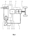
- Fig. 3
- zeigt ein gegenüber Fig. 2 beispielhaft konkretisiertes schematisches Blockschaltbild für ein Arbeitsfahrzeug mit einem hydraulischen Stellaggregat.
- Fig. 4
- zeigt ein gegenüber der Ausführungsform gemäß Fig. 2 konkretisiertes schematisches Blockschaltbild für ein Arbeitsfahrzeug mit einem hydraulischen Stellaggregat und einem hydraulisch mit dem Stellaggregat gekoppelten hydrostatischen Getriebe.
- Fig. 1
- shows a simplified representation of a trained as a wheel loader work vehicle, in which a trained as a blade tool is moved into a material accumulation to be ablated and a lifting function to be performed.
- Fig. 2
- shows a highly schematic block diagram of a working vehicle according to the invention.
- Fig. 3
- 2 shows an exemplary concrete block diagram for a work vehicle with a hydraulic control unit compared to FIG. 2.
- Fig. 4
- shows a comparison with the embodiment of FIG. 2 concretized schematic block diagram for a working vehicle with a hydraulic actuator and a hydraulically coupled to the actuator hydrostatic transmission.
Fig. 1 zeigt ein Arbeitsfahrzeug 1, welches hier als Radlader ausgebildet ist. Das Arbeitsfahrzeug 1 besitzt ein Hubgerüst 2, über welches ein Werkzeug 3, hier eine Schaufel, betätigbar ist. Mit einer derartigen Betätigung kann die Höhe des Werkzeugs 3 sowie dessen Neigungswinkel selektiv oder gemeinsam nach Maßgabe des Fahrers des Arbeitsfahrzeugs 1 geändert werden. Das Hubgerüst 2 besitzt einen Werkzeugarm 4, der im Bereich einer Schwenkachse 5 verdrehbar gegenüber dem Arbeitsfahrzeug 1 gelagert ist. Im vorderen Endbereich des Werkzeugarms 4 ist an diesem das Werkzeug 3 ebenfalls verschwenkbar für eine Kippbewegung angelenkt. Eine Verschwenkung des Werkzeugarms 4 um die Schwenkachse 5 kann nach Maßgabe eines Stellaggregats 6 erfolgen, welches für das dargestellte Ausführungsbeispiel als Hubzylinder ausgebildet ist. Gegenüber dem Werkzeugarm 4 ist zwischen seinen Endbereichen verdrehbar ein Kipphebel 7 gelagert, der über ein Stellaggregat 8, hier ein hydraulischer Kippzylinder, verschwenkbar ist. Das Stellaggregat 8 ist drehbar an den dem Arbeitsfahrzeug zugewandten Endbereich des Kipphebels 7 angelenkt und stützt sich an dem Arbeitsfahrzeug 1 ab. In dem anderen Endbereich ist der Kipphebel 7 an einer Kippstange 9 angelenkt. Die Kippstange 9 ist in ihrem anderen Endbereich beabstandet von dem Anlenkpunkt des Werkzeugarms 4 an dem Werkzeug 3 angelenkt. Werkzeugarm 4, Stellaggregate 6, 8, Kipphebel 7 und Kippstange 9 sind Teil einer an sich bekannten Z-Kinematik. Gemäß Fig. 1 kann das Arbeitsfahrzeug in eine Materialanhäufung 10 eingefahren werden. Der Fahrer kann über einen Steuerblock 11 eine Umschaltung von einem Betrieb "FAHREN" zu einem Betrieb "HEBEN" und/oder "KIPPEN" veranlassen. Zur Erhöhung der von einer Leistungsversorgung 12 bereitgestellten Leistung kann über das Gaspedal die Drehzahl einer Brennkraftmaschine des Arbeitsfahrzeugs 1 erhöht werden. Zum Anheben des Werkzeugs 3 wird das Stellaggregat 6 mit Hydraulikdruck beaufschlagt, woraus eine Hubkraft 13 resultiert, die ein Drehmoment des Werkzeugarms 4 um die Schwenkachse 5 erzeugt. Neben der Erzeugung der Hubkraft 13 ist die Leistungsversorgung 12 für die Erzeugung einer Vorschubleistung verantwortlich, so dass im Bereich des Werkzeugs 3 einerseits eine horizontal orientierte Widerstandskraft 14 erzeugt wird entgegen dem Vorschub und andererseits die Gewichtskraft 15 des Werkzeugs 3 zuzüglich einer von dem Werkzeug 3 abgestützten Last. Weitere Kräfte können durch eine überlagerte Kippbewegung bei simultaner Betätigung des Stellaggregats 8 oder bei einem Kippen mit reiner Hubbewegung erzeugt werden, beispielsweise durch Verlagerungen der Last und/oder Bewegung des Werkzeugs 3 in einer nicht rein vertikalen Bewegung, sondern beispielsweise auf einer Kreisbahn. Die Erfindung betrifft eine Reduzierung einer Vorschubleistung zur Erhöhung der Leistung, die für das Stellaggregat 6 und/oder das Stellaggregat 8 zur Verfügung steht.Fig. 1 shows a working
Fig. 2 zeigt ein schematisches Blockschaltbild mit einer Leistungsversorgung 12. Die Leistung der Leistungsversorgung 12 wird über eine Leistungsstelleinrichtung 16 auf die Stellaggregate 6, 8 und ein Vorschubaggregat 17 aufgeteilt. Die Beaufschlagung des Stellaggregats 6 und/oder des Stellaggregats 8 und u. U. auch des Vorschubaggregats 17 wird erfasst durch eine Überwachungseinrichtung 18. Die Überwachungseinrichtung 18 erzeugt ein der Beaufschlagung entsprechendes Signal 19, welches der Leistungsstelleinrichtung 16 zugeführt wird. Wird in der Leistungsstelleinrichtung 16 erkannt, dass ein erhöhter Leistungsbedarf für ein Stellaggregat 6, 8 besteht, erfolgt eine vergrößerte Leistungszuteilung zu dem Stellaggregat 6, 8 bei entsprechender Minderung der Leistungszuteilung des Vorschubaggregats 17. Ebenfalls berücksichtigt werden können in der Leistungsstelleinrichtung 16 Signale 20, bei denen es sich um Betriebsparameter des Arbeitsfahrzeugs 1 handeln kann und/oder von dem Fahrer des Arbeitsfahrzeugs 1 erzeugte Signale, beispielsweise Pedalsignale wie das Signal eines Bremspedals und/oder eines Inchpedals, manuelle Hub- oder Kippanforderungen o. ä.. Weiterhin kann in der Leistungsstelleinrichtung 16 ein Umgebungssignal 21 Berücksichtigung finden, bei dem es sich beispielsweise um eine ermittelte Neigung des Untergrunds des Arbeitsfahrzeugs 1 handelt. Über ein Signal 22 kann vom Fahrer auf die Leistungsversorgung eingewirkt werden. Ebenfalls möglich ist, dass die Leistungsversorgung 12 und die Leistungsstelleinrichtung 16 über ein Signal 23 kommunizieren, beispielsweise die Leistungsstelleinrichtung 16 einen erhöhten Leistungsbedarf an die Leistungsversorgung 12 signalisiert. FIG. 2 shows a schematic block diagram with a
Für die konstruktive Ausgestaltung des in Fig. 2 dargestellten Prinzips gibt es vielfältige Möglichkeiten:
- Beispielsweise können die dargestellten Komponenten elektrisch ausgeführt sein. In diesem Fall handelt es sich bei der Leistungsversorgung 12 um eine elektrische Leistungsversorgung.
Die Leistungsstelleinrichtung 16 kann als Steuer- oder Regelungseinrichtung mit einem Prozessor ausgebildet sein.Die Stellaggregate und das Vorschubaggregat 17 können als elektrische Stellaggregate ausgebildet sein.Die Überwachungseinrichtung 18 kann als Sensor, beispielsweise für eine Kraft, einen Weg, eine Geschwindigkeit, eine Beschleunigung, eine elektrische Größe indem Stellaggregat das Signal 20 Daten aus einem Speicher, beispielsweise ein Kennfeld, beinhaltet, welchevon der Leistungsstelleinrichtung 16 unter Berücksichtigung von Signalen 19-23 verarbeitet werden für die Veränderung der Zuteilung der Leistung zuden Stellaggregaten dem Vorschubaggregat 17. - Ebenfalls möglich ist, dass die
Leistungsversorgung 12 als Brennkraftmaschine des Arbeitsfahrzeugs 1 ausgebildet ist. In diesem Fall kann die Brennkraftmaschine beispielsweise ein hydrostatisches Getriebe mit einer Hydropumpe und einem Hydromotor antreiben und andererseits mindestens eine Pumpe antreiben, die für die Erzeugung eines Arbeitsdrucks in alsHubzylinder ausgebildeten Stellaggregaten Stellaggregate Bei der Überwachungseinrichtung 18 handelt es sich in diesem Fall bspw. um eine Erfassung des Arbeitsdrucks in den alsHubzylinder ausgebildeten Stellaggregaten - Ebenfalls möglich sind mechanische Ausführungsformen oder Kombinationen der zuvor erläuterten Grundprinzipien, beispielsweise eine Aufteilung der Leistung einer Brennkraftmaschine auf elektrische Aggregate, hydraulische Aggregate u. ä..
- For example, the components shown can be made electrically. In this case, the
power supply 12 is an electric power supply. Thepower adjustment device 16 may be designed as a control or regulating device with a processor. Theactuators feed unit 17 may be formed as electrical actuators. Themonitoring device 18 can be designed as a sensor, for example for a force, a path, a speed, an acceleration, an electrical variable in thecontrol unit signal 20 data from a memory, such as a map includes, which are processed by thepower control device 16, taking into account signals 19-23 for the change in the allocation of power to thecontrol units - It is also possible that the
power supply 12 is designed as an internal combustion engine of thework vehicle 1. In this case, the internal combustion engine can, for example, drive a hydrostatic transmission with a hydraulic pump and a hydraulic motor and, on the other hand, drive at least one pump which is used to generate a working pressure in actuatingunits actuators monitoring device 18 is, for example, a detection of the working pressure in theactuating units tool 3 and the power requirement. - Also possible are mechanical embodiments or combinations of the previously explained basic principles, for example, a division of the power of an internal combustion engine to electrical units, hydraulic units u. etc. ..
Fig. 3 zeigt eine erste detailliertere Ausgestaltung des in Fig. 2 dargestellten Grundprinzips. Hierbei ist das Stellaggregat 6 als Hubaggregat 24 oder Hubzylinder ausgebildet. Der Arbeitsdruck in dem Hubaggregat 24 wird von einer Pumpe 25 bereitgestellt. Zwischen Pumpe 25 und Hubaggregat 24 ist der Steuerblock 11 zwischengeschaltet, über den vom Fahrer unterschiedliche Betriebsbereiche "FAHREN", "HEBEN" und "KIPPEN" vorgegeben werden können. Als Signale 26 einer Überwachungseinrichtung 18 können alternativ oder kumulativ folgende Möglichkeiten genutzt werden:
- In einer Kolbenstange des Hubaggregats 24 wird eine Kraft, ein Weg, eine Geschwindigkeit oder eine Beschleunigung sensiert und in
ein Signal 26 umgewandelt. - In einer Arbeitskammer wird über einen Drucksensor ein Arbeitsdruck ermittelt, der
als Signal 26der Überwachungseinrichtung 18 zugeführt wird. - In einer Zuleitung
zu dem Hubaggregat 24 kannals Signal 26 ein Druck erfasst werden. - Ebenfalls erfasst werden kann der Druck in einer Leitung zwischen der Pumpe 25
und dem Steuerblock 11. - Schließlich kann ein Signal über den Betriebszustand der Pumpe 25
als Signal 26der Überwachungseinrichtung 18 zugeführt werden.
- In a piston rod of the lifting
unit 24, a force, a path, a speed or an acceleration is sensed and converted into asignal 26. - In a working chamber, a working pressure is determined via a pressure sensor, which is supplied as a
signal 26 to themonitoring device 18. - In a supply line to the
lifting unit 24 can be detected as asignal 26, a pressure. - Also can be detected, the pressure in a line between the
pump 25 and the control block eleventh - Finally, a signal about the operating state of the
pump 25 can be supplied as asignal 26 to themonitoring device 18.
Die Leistungsversorgung 12 ist beispielsweise mit einer Brennkraftmaschine gebildet, die die Leistung zentral der Leistungsstelleinrichtung 16 zuführt, wo die Leistung verzweigt in einen Leistungszweig 27, der zu der Pumpe 25 führt, sowie einen Leistungszweig 28, der zu den Fahrzeugrädern führt. Zur Bestimmung der Leistungsverteilung wird in der Leistungsstelleinrichtung 16 das Signal 19 der Überwachungseinrichtung 18 berücksichtigt, welches wiederum von dem mindestens einen Signal 26 abhängig ist.The
Gemäß Fig. 4 sind die Bauelemente 18, 12, 16 in Form hydraulischer Bauelemente ausgebildet. Ein Arbeitsdruck in der Arbeitsdruckleitung 38 zwischen der Pumpe 25 und dem Steuerblock 11 wird über eine Steuerdruckleitung 29 einem Steuerventil 30 zugeführt, welches in Fig. 4 schematisch als 2/2-Wegeventil dargestellt ist. Infolge einer Federbelastung des Steuerventils 30 befindet sich das Steuerventil 30 ohne anliegenden Steuerdruck der Steuerdruckleitung 29 oder unterhalb eines Schwellwerts in der skizzierten Sperrstellung, während mit einem Anstieg des Steuerdrucks in der Steuerdruckleitung 29 das Steuerventil 30 in eine Durchgangs-Betriebsstellung verbracht wird. Das Steuerventil 30 ist zwischen eine Pumpe 31 und einen Tank 32 zwischengeschaltet. Über den Druck der Pumpe 31 wird die Leistung eines hydrostatischen Getriebes 33 beeinflusst, indem über den erzeugten Druck in einer Steuerdruckleitung 36 die Förderleistung einer Hydropumpe 34 beeinflussbar ist. Die Pumpen 25, 31 sowie das hydrostatische Getriebe 33 werden von einem zentralen Antriebsaggregat, insbesondere einer Brennkraftmaschine, angetrieben.According to Fig. 4, the
Die Funktionsweise des in Fig. 4 dargestellten schematischen Aufbaus ist wie folgt: der Steuerdruck in der Steuerdruckleitung 29 korreliert mit dem Arbeitsdruck in dem Hubaggregat 24 und dem ausgangsseitig an der Pumpe 25 vorliegenden Druck. Mit zunehmender Belastung des Hubaggregats 24, also zunehmender Last an dem Werkzeug 3, beispielsweise im Zuge einer Hubbewegung, steigt somit der Steuerdruck 29 des Steuerventils 30. Das Steuerventil 30 bildet somit eine Überwachungseinrichtung 18 für die Beaufschlagung des Hubaggregats 24. Gleichzeitig ist das Steuerventil 30 Bestandteil einer Leistungsstelleinrichtung 16, da mit Überschreiten eines kritischen Steuerdrucks 29 das Steuerventil (teilweise) in eine Öffnungsstellung verbracht werden kann, für die die Pumpe 31 in den Tank 32 fördert, so dass der in der Steuerdruckleitung 36 anliegende Druck zur Vorgabe der Förderleistung der Hydropumpe 34 verringert wird. Hierdurch erfolgt eine "automatische" Leistungsanpassung für die Leistungszuteilung zu den Fahrzeugrädern des Arbeitsfahrzeugs 1.The operation of the schematic structure shown in Fig. 4 is as follows: the control pressure in the
In Fig. 4 ist das Steuerventil 30 symbolartig als "digitales" Ventil dargestellt, welches für ein Überschreiten eines Öffnungsdrucks durch den Steuerdruck 29 von einer Sperrstellung in eine Öffnungsstellung verbracht wird. Selbstverständlich kann das Steuerventil eine beliebige, kontinuierliche Öffnungscharakteristik aufweisen und beispielsweise als Steuerschieber ausgebildet sein, bei dem ein Öffnungsquerschnitt kontinuierlich vergrößert wird. Beispielsweise beträgt der Arbeitsdruck für das Hubaggregat 24 maximal 250 bar. Das Steuerventil 30 kann für einen Druck von ca. 20 bar unterhalb des Maximaldrucks in der Sperrstellung gemäß Fig. 4 verbleiben, während in Annäherung an den maximalen Druck von 230 bis 250 bar das Steuerventil 30 allmählich geöffnet wird. Zum weiteren Aufbau eines hydrostatischen Getriebes und dessen Steuerung wird auf die eingangs genannten Druckschriften verwiesen.In Fig. 4, the
- 11
- Arbeitsfahrzeugworking vehicle
- 22
- Hubgerüstmast
- 33
- WerkzeugTool
- 44
- Werkzeugarmtool arm
- 55
- Schwenkachseswivel axis
- 66
- Stellaggregatactuating assembly
- 77
- Kipphebelrocker arm
- 88th
- Stellaggregatactuating assembly
- 99
- Kippstangetilt rod
- 1010
- Materialanhäufungmaterial accumulation
- 1111
- Steuerblockcontrol block
- 1212
- Leistungsversorgungpower supply
- 1313
- Hubkraftlifting capacity
- 1414
- Widerstandskraftresistance
- 1515
- Gewichtskraftweight force
- 1616
- LeistungsstelleinrichtungPower setting device
- 1717
- Vorschubaggregatfeed unit
- 1818
- Überwachungseinrichtungmonitoring device
- 1919
- Signalsignal
- 2020
- Signalsignal
- 2121
- Umgebungssignalambient signal
- 2222
- Signalsignal
- 2323
- Signalsignal
- 2424
- Hubaggregatlifting unit
- 2525
- Pumpepump
- 2626
- Signalsignal
- 2727
- Leistungszweigpower branch
- 2828
- Leistungszweigpower branch
- 2929
- Steuerdruckcontrol pressure
- 3030
- Steuerventilcontrol valve
- 3131
- Pumpepump
- 3232
- Tanktank
- 3333
- hydrostatisches Getriebehydrostatic transmission
- 3434
- Hydropumpehydraulic pump
- 3535
- Vorschubaggregatfeed unit
- 3636
- weitere Steuerdruckleitungfurther control pressure line
- 3737
- ArbeitsdruckleitungWorking pressure line
- 3838
- ArbeitsdruckleitungWorking pressure line
Claims (9)
dadurch gekennzeichnet, dass
für das aktivierte Stellaggregat (6, 8) die Vorschubleistung des Vorschubaggregats (35) automatisch unter Berücksichtigung der Beaufschlagung des mindestens einen Stellaggregats (6, 8) beeinflusst wird.Method for operating a work vehicle (1) with an adjustable feed unit (35) and at least one control unit (6, 8) for a tool (3), in particular a bucket, wherein the feed unit (35) and the control unit (6, 8) have a have common power supply (12),
characterized in that
for the activated control unit (6, 8), the feed rate of the feed unit (35) is automatically influenced taking into account the action on the at least one control unit (6, 8).
Applications Claiming Priority (1)
| Application Number | Priority Date | Filing Date | Title |
|---|---|---|---|
| DE200610051549 DE102006051549A1 (en) | 2006-11-02 | 2006-11-02 | Work vehicle with a feed unit and a control unit and method for operating the same |
Publications (2)
| Publication Number | Publication Date |
|---|---|
| EP1918462A2 true EP1918462A2 (en) | 2008-05-07 |
| EP1918462A3 EP1918462A3 (en) | 2009-08-05 |
Family
ID=39106290
Family Applications (1)
| Application Number | Title | Priority Date | Filing Date |
|---|---|---|---|
| EP07020554A Withdrawn EP1918462A3 (en) | 2006-11-02 | 2007-10-20 | Work vehicle with a transmission system and a positioning system and method for operating the same |
Country Status (2)
| Country | Link |
|---|---|
| EP (1) | EP1918462A3 (en) |
| DE (1) | DE102006051549A1 (en) |
Cited By (1)
| Publication number | Priority date | Publication date | Assignee | Title |
|---|---|---|---|---|
| CN111783247A (en) * | 2020-06-29 | 2020-10-16 | 燕山大学 | Method and system for matching power mechanism and load of hydraulic valve control cylinder system in light weight mode |
Families Citing this family (1)
| Publication number | Priority date | Publication date | Assignee | Title |
|---|---|---|---|---|
| DE102019200079A1 (en) * | 2019-01-07 | 2020-07-09 | Zf Friedrichshafen Ag | Method and control device for loading a work tool of a work machine |
Citations (3)
| Publication number | Priority date | Publication date | Assignee | Title |
|---|---|---|---|---|
| US4776751A (en) * | 1987-08-19 | 1988-10-11 | Deere & Company | Crowd control system for a loader |
| EP0467440A1 (en) * | 1990-07-04 | 1992-01-22 | Hitachi Construction Machinery Co., Ltd. | Hydraulic driving circuit |
| US6766236B1 (en) * | 2003-06-27 | 2004-07-20 | Case, Llc | Skid steer drive control system |
Family Cites Families (4)
| Publication number | Priority date | Publication date | Assignee | Title |
|---|---|---|---|---|
| US3187497A (en) * | 1962-05-04 | 1965-06-08 | Hough Co Frank | Hydrostatic arrangement for tractor loaders |
| US5129229A (en) * | 1990-06-19 | 1992-07-14 | Hitachi Construction Machinery Co., Ltd. | Hydraulic drive system for civil-engineering and construction machine |
| DE4407282C2 (en) * | 1994-03-04 | 1996-04-18 | Hydromatik Gmbh | Hydrostatic drive |
| DE19509869B4 (en) * | 1995-03-17 | 2005-11-03 | Sauer-Danfoss Gmbh & Co Ohg | Control system for an automotive hydrostatic transmission |
-
2006
- 2006-11-02 DE DE200610051549 patent/DE102006051549A1/en not_active Ceased
-
2007
- 2007-10-20 EP EP07020554A patent/EP1918462A3/en not_active Withdrawn
Patent Citations (3)
| Publication number | Priority date | Publication date | Assignee | Title |
|---|---|---|---|---|
| US4776751A (en) * | 1987-08-19 | 1988-10-11 | Deere & Company | Crowd control system for a loader |
| EP0467440A1 (en) * | 1990-07-04 | 1992-01-22 | Hitachi Construction Machinery Co., Ltd. | Hydraulic driving circuit |
| US6766236B1 (en) * | 2003-06-27 | 2004-07-20 | Case, Llc | Skid steer drive control system |
Cited By (1)
| Publication number | Priority date | Publication date | Assignee | Title |
|---|---|---|---|---|
| CN111783247A (en) * | 2020-06-29 | 2020-10-16 | 燕山大学 | Method and system for matching power mechanism and load of hydraulic valve control cylinder system in light weight mode |
Also Published As
| Publication number | Publication date |
|---|---|
| EP1918462A3 (en) | 2009-08-05 |
| DE102006051549A1 (en) | 2008-05-15 |
Similar Documents
| Publication | Publication Date | Title |
|---|---|---|
| DE19530323B4 (en) | A control system for automatically controlling a work implement on an earthworking machine to receive material | |
| DE112010003541B4 (en) | WORKING VEHICLE | |
| DE112007002112B4 (en) | Construction Vehicle | |
| DE112010003519B4 (en) | working vehicle | |
| DE112011100394B4 (en) | HYDRAULIC EXCAVATORS AND CONTROL PROCESSES FOR A HYDRAULIC AGGER | |
| DE10350117B4 (en) | Hydraulically powered vehicle | |
| DE102019202664A1 (en) | Hydraulic reduction of stability control and calibration | |
| DE112016000049B4 (en) | Work vehicle and method for controlling output power of an engine | |
| DE112004000622T5 (en) | Engine output control unit | |
| DE112006002950T5 (en) | Construction Vehicle | |
| DE10246013A1 (en) | Forklift and control device and control method for a forklift | |
| EP3428011B1 (en) | Construction machine | |
| EP3587794A1 (en) | Hydrostatic drive and method for actuating a hydrostatic drive | |
| DE10393484B4 (en) | Method and device for controlling a hydraulic pump for a working device of a working vehicle | |
| EP1762535A2 (en) | Loader and method for loader | |
| WO2004007234A1 (en) | Method and device for controlling functions of an occupational vehicle | |
| DE10010670A1 (en) | Hydraulic lifting device for battery-operated industrial truck; has hydraulic lifting cylinder, hydraulic pump acting as motor for lowering and electric motor that acts as generator for lowering | |
| EP1608526B1 (en) | Engine assembly for driving a motor vehicle | |
| DE112015005464T5 (en) | Control system for a hybrid construction machine | |
| DE3507963A1 (en) | SPEED CONTROLLER FOR A SINGLE DRIVE IN GOOD HANDLING VEHICLES | |
| DE10012389B4 (en) | working machine | |
| EP1918462A2 (en) | Work vehicle with a transmission system and a positioning system and method for operating the same | |
| EP3517790B1 (en) | Working machine with hydraulics for energy recuperation | |
| DE112008002977T5 (en) | Component combination for a hydrostatically driven vehicle | |
| DE112013003534T5 (en) | Hydraulic drive system |
Legal Events
| Date | Code | Title | Description |
|---|---|---|---|
| PUAI | Public reference made under article 153(3) epc to a published international application that has entered the european phase |
Free format text: ORIGINAL CODE: 0009012 |
|
| AK | Designated contracting states |
Kind code of ref document: A2 Designated state(s): AT BE BG CH CY CZ DE DK EE ES FI FR GB GR HU IE IS IT LI LT LU LV MC MT NL PL PT RO SE SI SK TR |
|
| AX | Request for extension of the european patent |
Extension state: AL BA HR MK RS |
|
| RIN1 | Information on inventor provided before grant (corrected) |
Inventor name: NOTTMEIER, CORD Inventor name: HERMANNS, JOERG |
|
| PUAL | Search report despatched |
Free format text: ORIGINAL CODE: 0009013 |
|
| AK | Designated contracting states |
Kind code of ref document: A3 Designated state(s): AT BE BG CH CY CZ DE DK EE ES FI FR GB GR HU IE IS IT LI LT LU LV MC MT NL PL PT RO SE SI SK TR |
|
| AX | Request for extension of the european patent |
Extension state: AL BA HR MK RS |
|
| AKX | Designation fees paid | ||
| STAA | Information on the status of an ep patent application or granted ep patent |
Free format text: STATUS: THE APPLICATION IS DEEMED TO BE WITHDRAWN |
|
| 18D | Application deemed to be withdrawn |
Effective date: 20100206 |
|
| REG | Reference to a national code |
Ref country code: DE Ref legal event code: 8566 |