EP1918058A1 - High temperature electron beam welding - Google Patents
High temperature electron beam welding Download PDFInfo
- Publication number
- EP1918058A1 EP1918058A1 EP07119154A EP07119154A EP1918058A1 EP 1918058 A1 EP1918058 A1 EP 1918058A1 EP 07119154 A EP07119154 A EP 07119154A EP 07119154 A EP07119154 A EP 07119154A EP 1918058 A1 EP1918058 A1 EP 1918058A1
- Authority
- EP
- European Patent Office
- Prior art keywords
- welding
- components
- target temperature
- electron beam
- preheating
- Prior art date
- Legal status (The legal status is an assumption and is not a legal conclusion. Google has not performed a legal analysis and makes no representation as to the accuracy of the status listed.)
- Withdrawn
Links
Images
Classifications
-
- B—PERFORMING OPERATIONS; TRANSPORTING
- B23—MACHINE TOOLS; METAL-WORKING NOT OTHERWISE PROVIDED FOR
- B23K—SOLDERING OR UNSOLDERING; WELDING; CLADDING OR PLATING BY SOLDERING OR WELDING; CUTTING BY APPLYING HEAT LOCALLY, e.g. FLAME CUTTING; WORKING BY LASER BEAM
- B23K15/00—Electron-beam welding or cutting
- B23K15/0006—Electron-beam welding or cutting specially adapted for particular articles or work
-
- B—PERFORMING OPERATIONS; TRANSPORTING
- B23—MACHINE TOOLS; METAL-WORKING NOT OTHERWISE PROVIDED FOR
- B23K—SOLDERING OR UNSOLDERING; WELDING; CLADDING OR PLATING BY SOLDERING OR WELDING; CUTTING BY APPLYING HEAT LOCALLY, e.g. FLAME CUTTING; WORKING BY LASER BEAM
- B23K15/00—Electron-beam welding or cutting
- B23K15/06—Electron-beam welding or cutting within a vacuum chamber
-
- B—PERFORMING OPERATIONS; TRANSPORTING
- B23—MACHINE TOOLS; METAL-WORKING NOT OTHERWISE PROVIDED FOR
- B23K—SOLDERING OR UNSOLDERING; WELDING; CLADDING OR PLATING BY SOLDERING OR WELDING; CUTTING BY APPLYING HEAT LOCALLY, e.g. FLAME CUTTING; WORKING BY LASER BEAM
- B23K2101/00—Articles made by soldering, welding or cutting
- B23K2101/001—Turbines
Definitions
- This invention relates to welding techniques and more specifically, to electron beam welding of nickel or cobalt based superalloy components.
- Electron beam welding is increasingly being used to join subcomponents on superalloy gas turbine components, particularly, on buckets and nozzles. These components are frequently made from very high strength nickel or cobalt alloys that are difficult to weld. Oftentimes, ductile fillers or shims are used to reduce the cracking propensity in the weld fusion zone and heat-affected zone, but these techniques reduce the mechanical capability of the weld relative to the base metal.
- an electron beam welding process is provided for nickel or cobalt based superalloy components that includes locally preheating the part in situ prior to and during welding.
- Resistance, induction or radiant heating may be employed, and the heating system must be capable of raising the temperature of the component part to be welded to at least 1500°F and up to incipient melting of the base alloy and/or filler material.
- the component being welded is maintained at the elevated temperature, enabling welding of very highly alloyed base metals using matching strength and chemistry filler metals.
- the present invention relates to a method of welding superalloy components comprising: preheating one or more components to be welded to a target temperature of at least 1500°F in a vacuum chamber; welding the one or more preheated components in a weldment region utilizing an electron beam, while maintaining the target temperature until welding is completed.
- the invention in another aspect, relates to a method of welding superalloy turbine components comprising: preheating the one or more components to be welded to a pre-heat target temperature of at least 1500°F in a vacuum chamber, the preheating carried out using induction coils, resistance heaters or radiant lamps; supplying a filler metal to a weld zone; welding the one or more preheated components utilizing an electron beam, while maintaining the target temperature until the welding is completed.
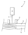
- FIG. 1 is a schematic drawing of an electron beam welding and preheat configuration in accordance with an exemplary embodiment of the invention.
- an electron beam welding apparatus 10 is shown by which an electron beam 12 generated by an electron beam gun 14 is directed at an interface formed by opposing surfaces of components 16, 18 to be joined.
- the beam 12 produces a weldment region (or simply a weldment) 20 that metallurgically joins the components.
- the components 16, 18 may be formed of a variety of metal alloys including those that are relatively difficult to weld such as precipitation strengthened nickel or cobalt-based superalloys used to form cast turbine components.
- the welding process is typically performed in an atmosphere suitable for electron beam welding, i.e., at a suitable vacuum level necessary to prevent electron scattering and rapid oxidation of the base metal.
- a suitable vacuum level necessary to prevent electron scattering and rapid oxidation of the base metal.
- the specific vacuum level as well as other parameters including pulsed current frequency of the electron beam and travel speed are known in the art and need not be described herein.
- a preheat system is located within the vacuum chamber.
- the preheat system is capable of locally heating the workpiece to at least 1500°F and up to incipient melting of the base alloy and/or filler (in some cases greater than 2000°F) (also referred to as the "target temperature”) and greater.
- the preheat system can employ induction coils, resistance heaters, or radiant (quartz) lamps, generally indicated in schematic form at 24, to heat the components while at the same time permitting beam access to the region to be welded. It will be appreciated that the vacuum chamber requires multiple electrical feed-throughs to provide power to the preheat system and to monitor the temperature.
- the joining can be accomplished autogenously (without filler materials), or by using one or more preplaced shims or wire fed filler material.
- Filler metals can have any range of capability, from highly ductile to very high strength.
- the temperature of the one or more components 16, 18 is elevated to the target temperature prior to energizing electron beam.
- the target temperature is maintained during welding, and heating ceases only upon completion of the welding process.
- the preheat system may be shut off, or it may remain in a controlled heating mode after welding and used to stress relieve the weld to avoid cracking upon cooling.
- the process described herein overcomes problems with prior preheating techniques used in conjunction with electron beam welding where the electron beam itself is run over the part at low part to locally increase the temperature of the part.
- the preheat process employed herein is considerably more controllable, allowing the operator to maintain a substantially uniform temperature of the one or more components through the entire welding process, independent of the electron beam itself.
Landscapes
- Engineering & Computer Science (AREA)
- Mechanical Engineering (AREA)
- Welding Or Cutting Using Electron Beams (AREA)
- Arc Welding In General (AREA)
- Laser Beam Processing (AREA)
Abstract
Description
- This invention relates to welding techniques and more specifically, to electron beam welding of nickel or cobalt based superalloy components.
- Electron beam welding is increasingly being used to join subcomponents on superalloy gas turbine components, particularly, on buckets and nozzles. These components are frequently made from very high strength nickel or cobalt alloys that are difficult to weld. Oftentimes, ductile fillers or shims are used to reduce the cracking propensity in the weld fusion zone and heat-affected zone, but these techniques reduce the mechanical capability of the weld relative to the base metal.
- In the fabrication and repair of the gas turbine buckets using gas arc welding (GTAW), very high temperature involve preheats have been in use for some time. Current methods preheating of bucket tips by radiant or induction heating to temperatures in excess of 1500°F. This enables the use of high strength fillers to produce welds with mechanical properties similar to the base material of the bucket.
- Current methods for preheating electron beam welds involve running the electron beam over the part at lower power to locally increase the temperature of the part. Temperature is less controllable using this method as it will vary greatly from one part to the next due to variation in the geometries of the parts. In addition, the preheat is not maintained during welding since the heating ceases when welding begins. Finally, since the electron beam is only applied to a single moving spot, and since the part is losing heat rapidly to conduction and radiation, the maximum temperature that can be reached is comparatively low.
- In an exemplary embodiment described herein, an electron beam welding process is provided for nickel or cobalt based superalloy components that includes locally preheating the part in situ prior to and during welding. Resistance, induction or radiant heating may be employed, and the heating system must be capable of raising the temperature of the component part to be welded to at least 1500°F and up to incipient melting of the base alloy and/or filler material. During welding, the component being welded is maintained at the elevated temperature, enabling welding of very highly alloyed base metals using matching strength and chemistry filler metals.
- Accordingly, in its broader aspects, the present invention relates to a method of welding superalloy components comprising: preheating one or more components to be welded to a target temperature of at least 1500°F in a vacuum chamber; welding the one or more preheated components in a weldment region utilizing an electron beam, while maintaining the target temperature until welding is completed.
- In another aspect, the invention relates to a method of welding superalloy turbine components comprising: preheating the one or more components to be welded to a pre-heat target temperature of at least 1500°F in a vacuum chamber, the preheating carried out using induction coils, resistance heaters or radiant lamps; supplying a filler metal to a weld zone; welding the one or more preheated components utilizing an electron beam, while maintaining the target temperature until the welding is completed.
- The invention will now be described in detail in connection with the Figure 1 which is a schematic drawing of an electron beam welding and preheat configuration in accordance with an exemplary embodiment of the invention.
- With reference to the Figure 1, an electron
beam welding apparatus 10 is shown by which anelectron beam 12 generated by anelectron beam gun 14 is directed at an interface formed by opposing surfaces ofcomponents beam 12 produces a weldment region (or simply a weldment) 20 that metallurgically joins the components. Thecomponents - The welding process is typically performed in an atmosphere suitable for electron beam welding, i.e., at a suitable vacuum level necessary to prevent electron scattering and rapid oxidation of the base metal. The specific vacuum level as well as other parameters including pulsed current frequency of the electron beam and travel speed are known in the art and need not be described herein. In accordance with an exemplary and non-limiting embodiment, a preheat system is located within the vacuum chamber. The preheat system is capable of locally heating the workpiece to at least 1500°F and up to incipient melting of the base alloy and/or filler (in some cases greater than 2000°F) (also referred to as the "target temperature") and greater. The preheat system can employ induction coils, resistance heaters, or radiant (quartz) lamps, generally indicated in schematic form at 24, to heat the components while at the same time permitting beam access to the region to be welded. It will be appreciated that the vacuum chamber requires multiple electrical feed-throughs to provide power to the preheat system and to monitor the temperature.
- In the event two components are to be welded (the invention also applied to, for example, repair of a single component), the joining can be accomplished autogenously (without filler materials), or by using one or more preplaced shims or wire fed filler material. Filler metals can have any range of capability, from highly ductile to very high strength.
- During welding, the temperature of the one or
more components - The process described herein overcomes problems with prior preheating techniques used in conjunction with electron beam welding where the electron beam itself is run over the part at low part to locally increase the temperature of the part. The preheat process employed herein is considerably more controllable, allowing the operator to maintain a substantially uniform temperature of the one or more components through the entire welding process, independent of the electron beam itself.
- While the invention has been described in connection with what is presently considered to be the most practical and preferred embodiment, it is to be understood that the invention is not to be limited to the disclosed embodiment, but on the contrary, is intended to cover various modifications and equivalent arrangements included within the scope of the appended claims.
Claims (10)
- A method of welding superalloy components comprising:preheating one or more components to be welded to a target temperature of at least 816°C (1500°F) in a vacuum chamber;welding the one or more preheated components in a weldment region utilizing an electron beam, while maintaining said target temperature until welding is completed.
- The method of claim 1 wherein, prior to welding, a filler is supplied to the weldment region.
- The method of claim 2 wherein said filler comprises a wire-fed filler metal.
- The method of claim 2 wherein said filler comprises one or more preplaced metal shims.
- The method of any preceding claim wherein preheating is carried out with induction coils, resistance heaters or radiant lamps.
- The method of claim 2 wherein said target temperature is between 816°C (1500°F) and incipient melting of said one or more components and/or said filler.
- The method of any preceding claim wherein said target temperature is greater than 1093°C (2000°F).
- The method of any preceding claim wherein, after welding, a controlled heating mode is maintained to stress relieve the weld.
- The method of any preceding claim wherein said superalloy components comprise high strength nickel or cobalt-based alloys.
- The method of any preceding claim comprising:preheating the one or more components to be welded to a pre-heat target temperature of at least 1500°F in a vacuum chamber, said preheating carried out using induction coils, resistance heaters or radiant lamps;supplying a filler metal to a weld zone;welding the one or more preheated components utilizing an electron beam, while maintaining said target temperature until the welding is completed.
Applications Claiming Priority (1)
| Application Number | Priority Date | Filing Date | Title |
|---|---|---|---|
| US11/591,466 US20080105659A1 (en) | 2006-11-02 | 2006-11-02 | High temperature electron beam welding |
Publications (1)
| Publication Number | Publication Date |
|---|---|
| EP1918058A1 true EP1918058A1 (en) | 2008-05-07 |
Family
ID=39032098
Family Applications (1)
| Application Number | Title | Priority Date | Filing Date |
|---|---|---|---|
| EP07119154A Withdrawn EP1918058A1 (en) | 2006-11-02 | 2007-10-24 | High temperature electron beam welding |
Country Status (4)
| Country | Link |
|---|---|
| US (1) | US20080105659A1 (en) |
| EP (1) | EP1918058A1 (en) |
| JP (1) | JP2008114290A (en) |
| CN (1) | CN101172316A (en) |
Families Citing this family (12)
| Publication number | Priority date | Publication date | Assignee | Title |
|---|---|---|---|---|
| US7802350B2 (en) * | 2007-07-27 | 2010-09-28 | United Technologies Corporation | Flange hole repair |
| US9381600B2 (en) * | 2008-07-22 | 2016-07-05 | Smith International, Inc. | Apparatus and methods to manufacture PDC bits |
| US9108266B2 (en) * | 2011-04-19 | 2015-08-18 | General Electric Company | Welded component, a welded gas turbine component, and a process of welding a component |
| US9028289B2 (en) | 2011-12-13 | 2015-05-12 | Federal-Mogul Ignition Company | Electron beam welded electrode for industrial spark plugs |
| US8657179B1 (en) | 2012-03-26 | 2014-02-25 | The United States Of America As Represented By The Administrator Of The National Aeronautics And Space Administration | Weld nugget temperature control in thermal stir welding |
| CN104057199A (en) * | 2014-06-30 | 2014-09-24 | 无锡市威海达机械制造有限公司 | Welding method of book page type metal structure |
| DE102015008919A1 (en) * | 2015-07-15 | 2017-01-19 | Evobeam GmbH | Process for the additive production of metallic components |
| FR3051831B1 (en) * | 2016-05-26 | 2018-05-18 | Safran Aircraft Engines | TURBOMACHINE EXHAUST CASE AND METHOD FOR MANUFACTURING THE SAME |
| US10987765B2 (en) * | 2016-08-17 | 2021-04-27 | Illinois Tool Works Inc. | Induction weld bead shaping |
| CN112317907B (en) * | 2020-10-27 | 2022-01-28 | 西门子爱克斯射线真空技术(无锡)有限公司 | Brazing device and method for anode target disc |
| CN112475581B (en) * | 2020-11-18 | 2022-05-20 | 中国兵器科学研究院宁波分院 | Vacuum electron beam welding method for large-size aircraft engine tail cone assembly |
| CN114101886B (en) * | 2021-12-30 | 2023-04-18 | 太原航空仪表有限公司 | Method for welding nickel-based high-temperature alloy membrane by electron beam |
Citations (2)
| Publication number | Priority date | Publication date | Assignee | Title |
|---|---|---|---|---|
| EP1116545A1 (en) * | 1999-12-17 | 2001-07-18 | Lufthansa Technik AG | Joining of single crystal turbine parts |
| EP1605068A2 (en) * | 2004-06-10 | 2005-12-14 | United Technologies Corporation | Homogeneous welding via pre-heating for high strength superalloy joining and material deposition |
Family Cites Families (9)
| Publication number | Priority date | Publication date | Assignee | Title |
|---|---|---|---|---|
| US4321453A (en) * | 1980-05-05 | 1982-03-23 | International Vacuum, Inc. | Electron-beam welding |
| DE3030532A1 (en) * | 1980-08-13 | 1982-03-18 | Brown, Boveri & Cie Ag, 6800 Mannheim | METHOD FOR RIP-FREE ENERGY BEAM WELDING OF HEAT-RESISTANT MOLDED PARTS |
| SE447804B (en) * | 1983-04-20 | 1986-12-15 | Kuroki Kogyosho Kk | PROCEDURE FOR MANUFACTURING COMPOSITE STALLS |
| US4903888A (en) * | 1988-05-05 | 1990-02-27 | Westinghouse Electric Corp. | Turbine system having more failure resistant rotors and repair welding of low alloy ferrous turbine components by controlled weld build-up |
| US5708253A (en) * | 1995-06-07 | 1998-01-13 | Hill Technical Services, Inc. | Apparatus and method for computerized interactive control, measurement and documentation of arc welding |
| US5714735A (en) * | 1996-06-20 | 1998-02-03 | General Electric Company | Method and apparatus for joining components with multiple filler materials |
| US6596411B2 (en) * | 2001-12-06 | 2003-07-22 | General Electric Company | High energy beam welding of single-crystal superalloys and assemblies formed thereby |
| US6639173B1 (en) * | 2003-04-30 | 2003-10-28 | General Electric Company | Electron beam welding method providing post-weld heat treatment |
| US7896986B2 (en) * | 2004-09-02 | 2011-03-01 | Siemens Energy, Inc. | Heat treatment of superalloy components |
-
2006
- 2006-11-02 US US11/591,466 patent/US20080105659A1/en not_active Abandoned
-
2007
- 2007-10-24 EP EP07119154A patent/EP1918058A1/en not_active Withdrawn
- 2007-10-31 JP JP2007282820A patent/JP2008114290A/en not_active Withdrawn
- 2007-11-02 CN CNA2007101692334A patent/CN101172316A/en active Pending
Patent Citations (2)
| Publication number | Priority date | Publication date | Assignee | Title |
|---|---|---|---|---|
| EP1116545A1 (en) * | 1999-12-17 | 2001-07-18 | Lufthansa Technik AG | Joining of single crystal turbine parts |
| EP1605068A2 (en) * | 2004-06-10 | 2005-12-14 | United Technologies Corporation | Homogeneous welding via pre-heating for high strength superalloy joining and material deposition |
Also Published As
| Publication number | Publication date |
|---|---|
| JP2008114290A (en) | 2008-05-22 |
| US20080105659A1 (en) | 2008-05-08 |
| CN101172316A (en) | 2008-05-07 |
Similar Documents
| Publication | Publication Date | Title |
|---|---|---|
| EP1918058A1 (en) | High temperature electron beam welding | |
| EP1944117A1 (en) | High temperature laser welding | |
| JP3218567B2 (en) | Welding of high-strength nickel-base superalloys. | |
| JP5736135B2 (en) | Double laser beam welding method for first and second filler metals | |
| US6084196A (en) | Elevated-temperature, plasma-transferred arc welding of nickel-base superalloy articles | |
| JP3209369U (en) | A system for starting and using a combination of filler wire feed and high-intensity energy source for root-pass welding of inner diameter of clad pipe | |
| KR100876171B1 (en) | Electron beam welding method | |
| US9527162B2 (en) | Laser additive repairing of nickel base superalloy components | |
| US8022330B2 (en) | Method and device for welding structural components | |
| CA2872312C (en) | Laser additive repairing of nickel base superalloy components | |
| EP1473106B1 (en) | Electron beam welding method providing post-weld heat treatment | |
| JPS6216894A (en) | Padding method for aluminum base metal | |
| JP2010240741A (en) | High power laser beam welding and its assembly | |
| CN112135705A (en) | Method and system for additive manufacturing or repair by in situ manufacturing and feeding of a sintering line | |
| JP5777296B2 (en) | Brazing repair method and gas turbine high temperature parts | |
| US20220281027A1 (en) | Electron-beam welding nickel-based superalloys, and device | |
| RU2686499C1 (en) | Method of repairing a cooled blade from a heat-resistant superalloy of a turbine of a gas turbine engine | |
| EP2846958B1 (en) | Laser additive repairing of nickel base superalloy components | |
| US10518359B2 (en) | Method of welding in deep joints | |
| US20220281041A1 (en) | Electron-beam welding of nickel-based superalloys, and device | |
| Welding | Experimental Analysis on the Mechanical Properties of Dissimilar Material Joint |
Legal Events
| Date | Code | Title | Description |
|---|---|---|---|
| PUAI | Public reference made under article 153(3) epc to a published international application that has entered the european phase |
Free format text: ORIGINAL CODE: 0009012 |
|
| AK | Designated contracting states |
Kind code of ref document: A1 Designated state(s): AT BE BG CH CY CZ DE DK EE ES FI FR GB GR HU IE IS IT LI LT LU LV MC MT NL PL PT RO SE SI SK TR |
|
| AX | Request for extension of the european patent |
Extension state: AL BA HR MK RS |
|
| 17P | Request for examination filed |
Effective date: 20081107 |
|
| AKX | Designation fees paid |
Designated state(s): AT BE BG CH CY CZ DE DK EE ES FI FR GB GR HU IE IS IT LI LT LU LV MC MT NL PL PT RO SE SI SK TR |
|
| 17Q | First examination report despatched |
Effective date: 20081222 |
|
| STAA | Information on the status of an ep patent application or granted ep patent |
Free format text: STATUS: THE APPLICATION IS DEEMED TO BE WITHDRAWN |
|
| 18D | Application deemed to be withdrawn |
Effective date: 20120503 |