EP1916757A2 - Cooling system for a portable generator - Google Patents
Cooling system for a portable generator Download PDFInfo
- Publication number
- EP1916757A2 EP1916757A2 EP07020702A EP07020702A EP1916757A2 EP 1916757 A2 EP1916757 A2 EP 1916757A2 EP 07020702 A EP07020702 A EP 07020702A EP 07020702 A EP07020702 A EP 07020702A EP 1916757 A2 EP1916757 A2 EP 1916757A2
- Authority
- EP
- European Patent Office
- Prior art keywords
- zone
- air
- fan
- cooling system
- generator
- Prior art date
- Legal status (The legal status is an assumption and is not a legal conclusion. Google has not performed a legal analysis and makes no representation as to the accuracy of the status listed.)
- Withdrawn
Links
Images
Classifications
-
- H—ELECTRICITY
- H02—GENERATION; CONVERSION OR DISTRIBUTION OF ELECTRIC POWER
- H02K—DYNAMO-ELECTRIC MACHINES
- H02K9/00—Arrangements for cooling or ventilating
- H02K9/02—Arrangements for cooling or ventilating by ambient air flowing through the machine
- H02K9/04—Arrangements for cooling or ventilating by ambient air flowing through the machine having means for generating a flow of cooling medium
- H02K9/06—Arrangements for cooling or ventilating by ambient air flowing through the machine having means for generating a flow of cooling medium with fans or impellers driven by the machine shaft
-
- F—MECHANICAL ENGINEERING; LIGHTING; HEATING; WEAPONS; BLASTING
- F02—COMBUSTION ENGINES; HOT-GAS OR COMBUSTION-PRODUCT ENGINE PLANTS
- F02B—INTERNAL-COMBUSTION PISTON ENGINES; COMBUSTION ENGINES IN GENERAL
- F02B63/00—Adaptations of engines for driving pumps, hand-held tools or electric generators; Portable combinations of engines with engine-driven devices
- F02B63/04—Adaptations of engines for driving pumps, hand-held tools or electric generators; Portable combinations of engines with engine-driven devices for electric generators
- F02B63/042—Rotating electric generators
-
- H—ELECTRICITY
- H02—GENERATION; CONVERSION OR DISTRIBUTION OF ELECTRIC POWER
- H02K—DYNAMO-ELECTRIC MACHINES
- H02K11/00—Structural association of dynamo-electric machines with electric components or with devices for shielding, monitoring or protection
- H02K11/04—Structural association of dynamo-electric machines with electric components or with devices for shielding, monitoring or protection for rectification
- H02K11/049—Rectifiers associated with stationary parts, e.g. stator cores
- H02K11/05—Rectifiers associated with casings, enclosures or brackets
-
- H—ELECTRICITY
- H02—GENERATION; CONVERSION OR DISTRIBUTION OF ELECTRIC POWER
- H02K—DYNAMO-ELECTRIC MACHINES
- H02K19/00—Synchronous motors or generators
- H02K19/16—Synchronous generators
- H02K19/36—Structural association of synchronous generators with auxiliary electric devices influencing the characteristic of the generator or controlling the generator, e.g. with impedances or switches
-
- F—MECHANICAL ENGINEERING; LIGHTING; HEATING; WEAPONS; BLASTING
- F02—COMBUSTION ENGINES; HOT-GAS OR COMBUSTION-PRODUCT ENGINE PLANTS
- F02B—INTERNAL-COMBUSTION PISTON ENGINES; COMBUSTION ENGINES IN GENERAL
- F02B63/00—Adaptations of engines for driving pumps, hand-held tools or electric generators; Portable combinations of engines with engine-driven devices
- F02B63/04—Adaptations of engines for driving pumps, hand-held tools or electric generators; Portable combinations of engines with engine-driven devices for electric generators
- F02B63/044—Adaptations of engines for driving pumps, hand-held tools or electric generators; Portable combinations of engines with engine-driven devices for electric generators the engine-generator unit being placed on a frame or in an housing
- F02B63/047—Movable engine-generator combinations on wheels
Definitions
- the present invention relates to a cooling system for and method of cooling a portable generator.
- Generators are known for supplying electrical power in remote locations, locations where access to standard utility power is unavailable, and in emergency situations when standard utility power to an area may be temporarily out of service. Generators are available in many different configurations, and use many different types and sizes of engines, depending generally upon the amount of electrical power the generator is designed to provide. Some generators are portable and include a fuel tank for supplying fuel to the internal combustion engine, and a frame for supporting the engine, the alternator, and the fuel tank. Some frames include wheels to facilitate movement of the generator. Other generators are standby units that are permanently mounted near a home, business or other structure.
- Generators generally have a frame construction or can be substantially enclosed in a housing. Some of the generator components, such as the alternator and the engine, each generate heat. However, other generator components, such as the controller, need to be kept cool. Enclosing the heat-generating components and the cool components in a single case can create issues for cooling the generator.
- the invention provides a method for cooling a generator.
- the method includes drawing air into a first zone of a housing through a first air intake, drawing air through a controller air intake adjacent a generator controller, directing air from the first zone into a second zone past a separator, drawing air into the second zone from both the first zone and the controller air intake, and exhausting air from the second zone to the exterior of the generator.
- the invention provides a cooling system for a generator.
- the cooling system includes a housing having a first zone and a second zone at least partially divided by a separator.
- the first zone includes an engine, a first fan rotatable by a crankshaft, a first air intake, and wherein substantially all air from the first zone is directed to the second zone.
- the second zone includes an alternator, a second fan, a second air intake, and wherein substantially all air from the second zone is directed to the exterior of the generator.
- the cooling system further includes a controller and an exhaust duct adjacent a muffler.
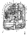
- Fig. 1 is an interior view of an embodiment of the present invention.
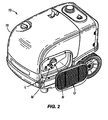
- Fig. 2 is a perspective view of a generator according to the present invention.
- Fig. 1 illustrates a generator 10 having a crankshaft engine 14 embodying the present invention.
- the generator 10 includes a housing 18, a first zone 22 and a second zone 26.
- the housing 18 encloses the generator components located in the first zone 22 and the second zone 26.
- the first zone 22 and the second zone 26 are divided by a separator F.
- Manifolds, or ducts 30, which enable air and exhaust gas movement throughout the internal structure of the generator, are also formed within the housing 18 of the generator 10.
- the housing 18 may be substantially of any construction to support the generator components.
- the housing can be composed of steel, plastic or similar material to enable appropriate generator support.
- the first zone 22 includes an engine 14, a blower housing A, a cowl or intake duct B, a flywheel C, a flywheel fan 34, and a head duct E adjacent to an engine cylinder head 15.
- the engine 14 in the first zone 22 is a heat-producing element which must be cooled to enable efficient generator operation.
- the cowl or intake duct B provides a passageway for intake air to enter the generator 10.
- the cowl or intake duct B is positioned substantially in a top wall of the generator 10.
- the cowl or intake duct B is coupled to the blower housing A, which completes the passageway for intake air to enter the first zone 22.
- the flywheel fan 34 is preferably integrally formed with the flywheel C.
- the flywheel fan 34 is rotatable by a crankshaft 38.
- the engine may have either a vertical crankshaft or a horizontal crankshaft.
- the rotation of the flywheel fan 34 creates a partial vacuum, or in effect, negative pressure in the first zone 22, which enables air movement throughout the first zone 22 toward the second zone 26.
- the head duct E provides a passageway for the air from the first zone 22 to enter the second zone 26.
- the second zone 26 includes a controller intake G, an electronic controller H and an alternator assembly 42.
- the alternator 42 in the second zone 26 is a heat-producing element which must be cooled to enable efficient generator operation.
- the controller intake G is adjacent to the controller H and provides a passageway for intake air to enter the second zone 26.
- the controller intake G is positioned substantially in a side wall of the generator 10.
- the controller H is the main electronic control unit of the generator 10 that provides AC output at a specific amplitude, waveform and frequency.
- the controller H generates heat and will shut down if it becomes overheated. Convective air provides the necessary cooling for the controller H. Additionally, the controller H needs to be kept cool so that it does not pick up heat from the other heat-producing components, namely the engine and the alternator.
- the alternator 42 includes a stator I, a rotor J and a rotor fan K.
- the stator I generates heat, but it does not rotate.
- the stator I contains the wire windings where current is generated.
- the stator I efficiency is in part a function of the winding temperature.
- the rotor J contains magnets that rotate around the stator I , and the rotor J is not significantly affected by temperature. Alternately, the windings could be on the rotor J and the magnets on the stator I .
- the rotor fan K is a scroll centrifugal fan coupled to a bottom side of the rotor J.
- the rotor fan K rotates with the rotor J and the crankshaft 38.
- the rotation of the rotor fan K and rotor J creates a partial vacuum in the second zone 26 which enables air movement within the second zone 26.
- a rotor duct L provides a passageway from the second zone 26 to the exterior of the generator 10 for expelling the air from the generator housing 18.
- the separator F at least partially divides the first zone 22 and the second zone 26.
- the separator is preferably a plate that provides a mounting surface for components housed in the first zone 22 and the second zone 26.
- the generator 10 further includes a muffler M, an exhaust deflector N and an exhaust vent O.
- the muffler M directs the hot engine exhaust gas to the exterior of the generator 10.
- the exhaust deflector N is a ninety degree exhaust deflector.
- the exhaust deflector N can be of any angular configuration capable of directing the hot engine exhaust gases from the muffler M to the rotor duct L.
- the exhaust deflector N is coupled to the muffler M to direct the hot engine exhaust gas from the muffler M to mix with the cooler air in the rotor duct L.
- the exhaust vent O is positioned on the exterior of the generator 10 and provides a passageway for the mixture of exhaust gas from the muffler M and the air in the rotor duct L to be expelled to the exterior of the generator 10.
- air is drawn into the first zone 22 through the cowl or upper intake B.
- the cowl or intake B is coupled to the blower housing A to complete the passageway for intake air to enter the first zone 22.
- the rotation of the flywheel C causes the intake air to flow across the engine 14, providing cooling air to the engine 14.
- the air is then directed to the head duct E which provides a passageway and directs the air from the first zone 22 to the second zone 26 through an aperture 46 in the separator plate F.
- the air from the first zone 22 follows two paths 50, 54 in the second zone 26.
- the first path 50 directs a portion of the air from the first zone 22 to enter the rotor fan K from a bottom side of the rotor fan K.
- the second path 54 directs a portion of the air from the first zone 22 to flow through a passageway in the rotor J and then through a top side of the rotor fan K.
- Air is also drawn into the second zone 26 through the controller intake G.
- the two paths 50, 54 are on a side of the generator 10 opposite the controller H to keep the hot air entering the second zone 26 from the first zone 22 away from the controller H.
- Intake air from the controller intake G flows across the controller H to cool the controller H. As the air flows past the controller H, the air is further drawn into the second zone 26 by the partial vacuum created by the rotation of the rotor fan K.
- the air in the second zone 26 from the first path 50, the second path 54 and the controller intake G converges at the rotor fan K where the air is expelled from the second zone 26 through the rotor duct L.
- the rotor duct L provides a passageway for the air to move from the second zone 26 to the exterior of the generator 10.
- the exhaust deflector N directs the hot muffler M engine exhaust gas into the stream of cooler air in the rotor duct L.
- the hot muffler M exhaust gas mixes with the cool second zone 26 air in the rotor duct L at the exhaust deflector N to further cool the air before it is expelled to the exterior of the generator 10.
- the mixed exhaust gas is finally expelled from the generator 10 at the exhaust vent O located on the exterior of the generator 10.
Abstract
Description
- This application claims priority to Provisional Patent Application Serial No.
60/853,845 filed on October 24,2006 - The present invention relates to a cooling system for and method of cooling a portable generator.
- Generators are known for supplying electrical power in remote locations, locations where access to standard utility power is unavailable, and in emergency situations when standard utility power to an area may be temporarily out of service. Generators are available in many different configurations, and use many different types and sizes of engines, depending generally upon the amount of electrical power the generator is designed to provide. Some generators are portable and include a fuel tank for supplying fuel to the internal combustion engine, and a frame for supporting the engine, the alternator, and the fuel tank. Some frames include wheels to facilitate movement of the generator. Other generators are standby units that are permanently mounted near a home, business or other structure.
- Generators generally have a frame construction or can be substantially enclosed in a housing. Some of the generator components, such as the alternator and the engine, each generate heat. However, other generator components, such as the controller, need to be kept cool. Enclosing the heat-generating components and the cool components in a single case can create issues for cooling the generator.
- In one embodiment, the invention provides a method for cooling a generator. The method includes drawing air into a first zone of a housing through a first air intake, drawing air through a controller air intake adjacent a generator controller, directing air from the first zone into a second zone past a separator, drawing air into the second zone from both the first zone and the controller air intake, and exhausting air from the second zone to the exterior of the generator.
- In another embodiment, the invention provides a cooling system for a generator. The cooling system includes a housing having a first zone and a second zone at least partially divided by a separator. The first zone includes an engine, a first fan rotatable by a crankshaft, a first air intake, and wherein substantially all air from the first zone is directed to the second zone. The second zone includes an alternator, a second fan, a second air intake, and wherein substantially all air from the second zone is directed to the exterior of the generator. The cooling system further includes a controller and an exhaust duct adjacent a muffler.
- Other aspects of the invention will become apparent by consideration of the detailed description and accompanying drawings.
- Fig. 1 is an interior view of an embodiment of the present invention.
- Fig. 2 is a perspective view of a generator according to the present invention.
- Before any embodiments of the invention are explained in detail, it is to be understood that the invention is not limited in its application to the details of construction and the arrangement of components set forth in the following description or illustrated in the drawings. The invention is capable of other embodiments and of being practiced or of being carried out in various ways. Also, it is to be understood that the phraseology and terminology used herein is for the purpose of description and should not be regarded as limiting. The use of"including" and "comprising" and variations thereof herein is meant to encompass the items listed thereafter and equivalents thereof as well as additional items.
- Fig. 1 illustrates a
generator 10 having acrankshaft engine 14 embodying the present invention. Thegenerator 10 includes ahousing 18, afirst zone 22 and asecond zone 26. Thehousing 18 encloses the generator components located in thefirst zone 22 and thesecond zone 26. Thefirst zone 22 and thesecond zone 26 are divided by a separator F. Manifolds, orducts 30, which enable air and exhaust gas movement throughout the internal structure of the generator, are also formed within thehousing 18 of thegenerator 10. - The
housing 18 may be substantially of any construction to support the generator components. The housing can be composed of steel, plastic or similar material to enable appropriate generator support. - The
first zone 22 includes anengine 14, a blower housing A, a cowl or intake duct B, a flywheel C, aflywheel fan 34, and a head duct E adjacent to anengine cylinder head 15. Theengine 14 in thefirst zone 22 is a heat-producing element which must be cooled to enable efficient generator operation. The cowl or intake duct B provides a passageway for intake air to enter thegenerator 10. The cowl or intake duct B is positioned substantially in a top wall of thegenerator 10. The cowl or intake duct B is coupled to the blower housing A, which completes the passageway for intake air to enter thefirst zone 22. Theflywheel fan 34 is preferably integrally formed with the flywheel C. Theflywheel fan 34 is rotatable by acrankshaft 38. The engine may have either a vertical crankshaft or a horizontal crankshaft. The rotation of theflywheel fan 34 creates a partial vacuum, or in effect, negative pressure in thefirst zone 22, which enables air movement throughout thefirst zone 22 toward thesecond zone 26. The head duct E provides a passageway for the air from thefirst zone 22 to enter thesecond zone 26. - The
second zone 26 includes a controller intake G, an electronic controller H and analternator assembly 42. Thealternator 42 in thesecond zone 26 is a heat-producing element which must be cooled to enable efficient generator operation. The controller intake G is adjacent to the controller H and provides a passageway for intake air to enter thesecond zone 26. The controller intake G is positioned substantially in a side wall of thegenerator 10. The controller H is the main electronic control unit of thegenerator 10 that provides AC output at a specific amplitude, waveform and frequency. The controller H generates heat and will shut down if it becomes overheated. Convective air provides the necessary cooling for the controller H. Additionally, the controller H needs to be kept cool so that it does not pick up heat from the other heat-producing components, namely the engine and the alternator. - The
alternator 42 includes a stator I, a rotor J and a rotor fan K. The stator I generates heat, but it does not rotate. The stator I contains the wire windings where current is generated. The stator I efficiency is in part a function of the winding temperature. The rotor J contains magnets that rotate around the stator I, and the rotor J is not significantly affected by temperature. Alternately, the windings could be on the rotor J and the magnets on the stator I. - The rotor fan K is a scroll centrifugal fan coupled to a bottom side of the rotor J. The rotor fan K rotates with the rotor J and the
crankshaft 38. The rotation of the rotor fan K and rotor J creates a partial vacuum in thesecond zone 26 which enables air movement within thesecond zone 26. A rotor duct L provides a passageway from thesecond zone 26 to the exterior of thegenerator 10 for expelling the air from thegenerator housing 18. - The separator F at least partially divides the
first zone 22 and thesecond zone 26. The separator is preferably a plate that provides a mounting surface for components housed in thefirst zone 22 and thesecond zone 26. - With reference to Fig. 2, the
generator 10 further includes a muffler M, an exhaust deflector N and an exhaust vent O. The muffler M directs the hot engine exhaust gas to the exterior of thegenerator 10. In the illustrated embodiment, the exhaust deflector N is a ninety degree exhaust deflector. However, the exhaust deflector N can be of any angular configuration capable of directing the hot engine exhaust gases from the muffler M to the rotor duct L. The exhaust deflector N is coupled to the muffler M to direct the hot engine exhaust gas from the muffler M to mix with the cooler air in the rotor duct L. The exhaust vent O is positioned on the exterior of thegenerator 10 and provides a passageway for the mixture of exhaust gas from the muffler M and the air in the rotor duct L to be expelled to the exterior of thegenerator 10. - During generator operation and with reference to both Figs. 1 and 2, air is drawn into the
first zone 22 through the cowl or upper intake B. The cowl or intake B is coupled to the blower housing A to complete the passageway for intake air to enter thefirst zone 22. The rotation of the flywheel C causes the intake air to flow across theengine 14, providing cooling air to theengine 14. The air is then directed to the head duct E which provides a passageway and directs the air from thefirst zone 22 to thesecond zone 26 through anaperture 46 in the separator plate F. - The air from the
first zone 22 follows twopaths second zone 26. Thefirst path 50 directs a portion of the air from thefirst zone 22 to enter the rotor fan K from a bottom side of the rotor fan K. Thesecond path 54 directs a portion of the air from thefirst zone 22 to flow through a passageway in the rotor J and then through a top side of the rotor fan K.
Air is also drawn into thesecond zone 26 through the controller intake G. The twopaths generator 10 opposite the controller H to keep the hot air entering thesecond zone 26 from thefirst zone 22 away from the controller H. Intake air from the controller intake G flows across the controller H to cool the controller H. As the air flows past the controller H, the air is further drawn into thesecond zone 26 by the partial vacuum created by the rotation of the rotor fan K. - The air in the
second zone 26 from thefirst path 50, thesecond path 54 and the controller intake G converges at the rotor fan K where the air is expelled from thesecond zone 26 through the rotor duct L. With reference to Fig. 2, the rotor duct L provides a passageway for the air to move from thesecond zone 26 to the exterior of thegenerator 10. The exhaust deflector N directs the hot muffler M engine exhaust gas into the stream of cooler air in the rotor duct L. The hot muffler M exhaust gas mixes with the coolsecond zone 26 air in the rotor duct L at the exhaust deflector N to further cool the air before it is expelled to the exterior of thegenerator 10. The mixed exhaust gas is finally expelled from thegenerator 10 at the exhaust vent O located on the exterior of thegenerator 10. - Various features and advantages of the invention are set forth in the following claims.
Claims (34)
- A method for cooling a generator, the method comprising:drawing air into a first zone of a housing through a first air intake;drawing air through a controller air intake adjacent a generator controller;directing air from the first zone into a second zone past a separator;drawing air into the second zone from both the first zone and the controller air intake; andexhausting air from the second zone to the exterior of the generator.
- The method of claim 1, further comprising rotating a first fan with a crankshaft to create a partial vacuum in the first zone.
- The method of claim 2, further comprising rotating a second fan to create a partial vacuum in the second zone, wherein the second fan has a shaft that is coaxial with the crankshaft.
- The method of claim 1, wherein a first fan and a second fan are coaxial and attached to the crankshaft.
- The method of claim 1, wherein the first zone is positioned substantially vertically above the second zone.
- The method of claim 1, wherein the first air intake is positioned substantially in a top wall of the generator, and wherein the controller air intake is positioned substantially in a side wall of the generator.
- The method of claim 1, wherein air from the first zone follows both a first path and a second path in the second zone.
- The method of claim 7, wherein the first path and the second path each include a respective duct disposed in the housing of the generator.
- The method of claim 7, wherein air in the first path enters a second fan from a bottom side of the second fan.
- The method of claim 9, wherein air in the second path enters an alternator.
- The method of claim 10, wherein air in the alternator enters the second fan from a top side of the second fan.
- The method of claim 7, wherein air in the second zone from the first path, the second path, and the controller air intake converges near a rotor fan, and wherein the converged air is thereafter expelled through a rotor duct.
- The method of claim 12, wherein air expelled from the rotor duct mixes with exhaust gases from a muffler.
- The method of claim 13, wherein the mixed exhaust gases are expelled to the exterior of the generator.
- The method of claim 1, wherein a head duct is positioned substantially adjacent a cylinder head of an engine to cool the cylinder head.
- A cooling system for a generator, the cooling system comprising:a housing having a first zone and a second zone at least partially divided by a separator,the first zone comprising:an engine;a first fan rotatable by a crankshaft;a first air intake; andwherein substantially all air from the first zone is directed to the second zone;the second zone comprising:an alternator;a second fan;a second air intake; andwherein substantially all air from the second zone is directed to theexterior of the generator;a controller; andan exhaust duct adjacent a muffler.
- The cooling system of claim 16, wherein the second fan has a fan shaft that is coaxial with the crankshaft.
- The cooling system of claim 16, wherein the engine has a vertical crankshaft.
- The cooling system of claim 16, wherein the first fan is a flywheel fan.
- The cooling system of claim 16, wherein the first zone is positioned substantially vertically above the second zone.
- The cooling system of claim 16, wherein the first fan rotates to create a partial vacuum to draw air into the first zone.
- The cooling system of claim 16, wherein the first air intake is positioned substantially in a top wall of the generator, and wherein the second air intake is positioned substantially in a side wall of the generator.
- The cooling system of claim 22, wherein the controller is positioned substantially adjacent the second air intake.
- The cooling system of claim 16, wherein the generator is an inverter generator.
- The cooling system of claim 16, wherein the separator is a plate having a fluid flow aperture.
- The cooling system of claim 23, wherein intake air from the second air intake flows substantially adjacent to the controller to cool the controller.
- The cooling system of claim 16, wherein air from the first zone follows a first path and a second path in the second zone.
- The cooling system of claim 27, wherein the first path and the second path each include a respective duct formed in the housing of the generator.
- The cooling system of claim 27, wherein air in the first path enters the second fan from a bottom side of the second fan.
- The cooling system of claim 27, wherein air in the second path enters the alternator.
- The cooling system of claim 30, wherein air in the alternator enters the second fan from a top side of the second fan.
- The cooling system of claim 27, wherein air in the first path, second path, and the second air intake converges near a rotor, wherein converged air is thereafter expelled to the exhaust duct.
- The cooling system of claim 32, wherein the exhaust duct is substantially positioned such that substantially all of the exhaust gas from the muffler is mixed with air from the second zone.
- The cooling system of claim 16, further comprising a head duct positioned substantially adjacent a cylinder head of the engine to cool the cylinder head.
Applications Claiming Priority (1)
| Application Number | Priority Date | Filing Date | Title |
|---|---|---|---|
| US85384506P | 2006-10-24 | 2006-10-24 |
Publications (2)
| Publication Number | Publication Date |
|---|---|
| EP1916757A2 true EP1916757A2 (en) | 2008-04-30 |
| EP1916757A3 EP1916757A3 (en) | 2013-11-13 |
Family
ID=38659071
Family Applications (1)
| Application Number | Title | Priority Date | Filing Date |
|---|---|---|---|
| EP07020702.2A Withdrawn EP1916757A3 (en) | 2006-10-24 | 2007-10-23 | Cooling system for a portable generator |
Country Status (2)
| Country | Link |
|---|---|
| US (1) | US7492050B2 (en) |
| EP (1) | EP1916757A3 (en) |
Families Citing this family (22)
| Publication number | Priority date | Publication date | Assignee | Title |
|---|---|---|---|---|
| JP2008255831A (en) * | 2007-04-02 | 2008-10-23 | Yamaha Motor Powered Products Co Ltd | Soundproof engine generator |
| US8251173B2 (en) | 2009-07-23 | 2012-08-28 | Briggs & Stratton Corporation | Muffler attachment system |
| US8220429B2 (en) * | 2009-07-23 | 2012-07-17 | Briggs & Stratton Corporation | Overhead valve and rocker arm configuration for a small engine |
| US8424498B2 (en) | 2009-07-23 | 2013-04-23 | Briggs & Stratton Corporation | Engine blower scroll |
| US8251030B2 (en) | 2009-07-23 | 2012-08-28 | Briggs & Stratton Corporation | Rocker cover system |
| USD668607S1 (en) | 2010-03-08 | 2012-10-09 | Briggs & Stratton Corporation | Frame for outdoor power equipment |
| JP5597571B2 (en) * | 2011-02-15 | 2014-10-01 | ヤンマー株式会社 | Package storage engine working machine |
| US8890340B2 (en) | 2011-11-04 | 2014-11-18 | Kohler, Inc. | Fan configuration for an engine driven generator |
| US8544425B2 (en) | 2011-11-04 | 2013-10-01 | Kohler Co. | Engine driven generator that is cooled by a first electrical fan and a second electrical fan |
| EP2767675A1 (en) * | 2013-02-15 | 2014-08-20 | Siemens Aktiengesellschaft | Through flow ventilation system for a power generation turbine package |
| US9291114B2 (en) | 2013-02-28 | 2016-03-22 | Briggs & Stratton Corporation | Generator including a fuel shutoff valve |
| US9143018B2 (en) | 2013-03-08 | 2015-09-22 | Kohler Co. | Power generation system with controlled enclosure openings |
| US10079525B2 (en) * | 2013-09-27 | 2018-09-18 | Cummins, Inc. | Electrical power generation system with multiple path cooling |
| US10060343B2 (en) | 2014-12-09 | 2018-08-28 | Generac Power Systems, Inc. | Air flow system for an enclosed portable generator |
| JP6619252B2 (en) * | 2016-02-10 | 2019-12-11 | 本田技研工業株式会社 | Engine generator |
| JP6619253B2 (en) * | 2016-02-10 | 2019-12-11 | 本田技研工業株式会社 | Engine generator |
| CN105846592B (en) * | 2016-03-28 | 2018-07-03 | 江苏杰特动力科技有限公司 | A kind of variable-frequency power generation unit enters the wind cooling system |
| US10533576B2 (en) | 2016-09-16 | 2020-01-14 | Cummins Power Generation Ip, Inc. | Fan inlet cone for improved sealing with a genset fan and housing |
| US10744586B2 (en) | 2017-11-28 | 2020-08-18 | Lincoln Global, Inc. | Engine driven welder |
| US10786859B2 (en) | 2017-11-28 | 2020-09-29 | Lincoln Global, Inc. | Engine driven welder |
| JP1637079S (en) * | 2019-02-15 | 2019-07-22 | ||
| JP1637080S (en) * | 2019-02-15 | 2019-07-22 |
Family Cites Families (69)
| Publication number | Priority date | Publication date | Assignee | Title |
|---|---|---|---|---|
| US2209363A (en) | 1939-03-21 | 1940-07-30 | Westinghouse Electric & Mfg Co | Ventilation system |
| US2355208A (en) | 1943-07-05 | 1944-08-08 | Maguire Ind Inc | Motor-generator |
| US3259752A (en) | 1962-10-24 | 1966-07-05 | Honda Gijutsu Kenkyusho Kk | Portable engine |
| US4243893A (en) | 1978-11-03 | 1981-01-06 | Aktiebolaget Electrolux | Supplemental cooling system for portable electric power plants |
| IT8253142V0 (en) | 1982-03-31 | 1982-03-31 | Fiat Auto Spa | GENERATOR APPARATUS FOR THE COMBINED PRODUCTION OF ELECTRICITY AND HEAT |
| DE3410976A1 (en) | 1983-03-18 | 1984-10-04 | Honda Giken Kogyo K.K., Tokio/Tokyo | COMPLETELY ENCLOSED, PORTABLE GENERATOR |
| GB2141782B (en) | 1983-05-11 | 1987-01-07 | Honda Motor Co Ltd | Portable engine-generator sets |
| FI68707C (en) | 1984-02-09 | 1985-10-10 | Valmet Oy | DIESELAGGREGAT |
| JPS6140425A (en) * | 1984-07-31 | 1986-02-26 | Yanmar Diesel Engine Co Ltd | Case containing type engine generator |
| US4647835A (en) | 1984-12-19 | 1987-03-03 | Kawasaki Jukogyo Kabushiki Kaisha | Portable generator |
| US4677940A (en) | 1985-08-09 | 1987-07-07 | Kohler Co. | Cooling system for a compact generator |
| US4702201A (en) | 1985-10-04 | 1987-10-27 | Honda Giken Kogyo Kabushiki Kaisha | Soundproof type engine working machine |
| US4859886A (en) | 1986-02-28 | 1989-08-22 | Honda Giken Kogyo Kabushiki Kaisha | Portable engine-operated electric generator |
| JPS6356144A (en) | 1986-08-25 | 1988-03-10 | Kubota Ltd | Cooling structure of engine generator |
| GB2196486B (en) | 1986-08-25 | 1990-06-06 | Kubota Ltd | Forcedly air-cooled engine generator of vertical shaft-type |
| US4827147A (en) | 1986-11-12 | 1989-05-02 | Honda Giken Kogyo Kabushiki Kaisha | Engine-powered portable working apparatus |
| US4835405A (en) | 1987-11-30 | 1989-05-30 | Onan Corporation | Generator set and method |
| JPH0617648B2 (en) | 1987-12-02 | 1994-03-09 | 株式会社クボタ | Engine generator with cover |
| US4907546A (en) | 1987-12-02 | 1990-03-13 | Kubota Ltd. | Air-cooled type cooling system for engine working machine assembly |
| JP2901774B2 (en) | 1990-04-13 | 1999-06-07 | ヤマハ発動機株式会社 | Engine driven generator |
| JPH05312050A (en) | 1992-05-01 | 1993-11-22 | Kubota Corp | Ventilating and cooling system in soundproofing type engine generator |
| JPH0688524A (en) | 1992-09-08 | 1994-03-29 | Kubota Corp | Engine part structure of farm working vehicle |
| US5433175A (en) | 1993-11-30 | 1995-07-18 | Onan Corporation | Generator air flow and noise management system and method |
| US5929611A (en) * | 1994-09-14 | 1999-07-27 | Coleman Powermate, Inc. | Light weight rotor and stator with multiple coil windings in thermal contact |
| US5705917A (en) * | 1994-09-14 | 1998-01-06 | Coleman Powermate, Inc. | Light weight machine with rotor employing permanent magnets and consequence poles |
| US5890460A (en) | 1995-05-08 | 1999-04-06 | Ball; Ronald C. | Electrical generator set |
| US5515816A (en) | 1995-05-08 | 1996-05-14 | Ball; Ronald | Electrical generator set |
| US5694889A (en) | 1995-05-08 | 1997-12-09 | Ball; Ronald C. | Electrical generator set |
| US5624589A (en) | 1995-09-11 | 1997-04-29 | Illinois Tool Works Inc. | Segregated cooling air flow for engine driven welder |
| US5626105A (en) | 1995-10-24 | 1997-05-06 | Kohler Co. | Vertical shaft generator with single cooling fan |
| US5965999A (en) | 1997-03-20 | 1999-10-12 | Coleman Powermate, Inc. | Vertical generator assembly |
| JP3815703B2 (en) | 1997-07-24 | 2006-08-30 | 本田技研工業株式会社 | Engine generator |
| JP3800373B2 (en) | 1997-07-24 | 2006-07-26 | 本田技研工業株式会社 | Engine generator |
| JP3800372B2 (en) | 1997-07-24 | 2006-07-26 | 本田技研工業株式会社 | Engine generator |
| US5977644A (en) | 1997-08-26 | 1999-11-02 | Lucent Technologies Inc. | Backup power system having improved cooling airflow and method of operation thereof |
| JPH1193690A (en) | 1997-09-24 | 1999-04-06 | Sts Kk | Gas turbine driving power unit |
| JP3347044B2 (en) | 1998-01-19 | 2002-11-20 | 本田技研工業株式会社 | Portable engine working machine |
| JP3347045B2 (en) | 1998-01-19 | 2002-11-20 | 本田技研工業株式会社 | Engine working machine |
| US5908011A (en) * | 1998-02-02 | 1999-06-01 | Stauffer Diesel, Inc. | Reduced length engine generator assembly |
| US5899174A (en) | 1998-02-06 | 1999-05-04 | Anderson; Wayne A. | Enclosed engine generator set |
| JP3531716B2 (en) | 1998-04-17 | 2004-05-31 | 本田技研工業株式会社 | Engine driven work machine |
| JP2000328956A (en) | 1999-05-20 | 2000-11-28 | Honda Motor Co Ltd | Engine power generator |
| JP3727488B2 (en) | 1999-05-21 | 2005-12-14 | 本田技研工業株式会社 | Engine generator |
| JP3654567B2 (en) | 1999-05-21 | 2005-06-02 | 本田技研工業株式会社 | Engine generator |
| JP2000328957A (en) | 1999-05-21 | 2000-11-28 | Honda Motor Co Ltd | Engine power generator |
| JP3754579B2 (en) | 1999-07-12 | 2006-03-15 | 本田技研工業株式会社 | Engine working machine |
| JP2001221047A (en) * | 2000-02-09 | 2001-08-17 | Fuji Heavy Ind Ltd | Engine generator |
| JP2001221054A (en) | 2000-02-09 | 2001-08-17 | Fuji Heavy Ind Ltd | Engine generator |
| US6626140B2 (en) | 2000-02-29 | 2003-09-30 | Bombardier-Rotax Gmbh | Four stroke engine having power take off assembly |
| JP3866480B2 (en) | 2000-04-14 | 2007-01-10 | 富士重工業株式会社 | Engine generator |
| US6499441B2 (en) | 2000-04-14 | 2002-12-31 | Fuji Jukogyo Kabushiki Kaisha | Engine generator |
| US6376944B1 (en) | 2000-07-11 | 2002-04-23 | Eagle-Picher Industries, Inc. | Electrical power generator |
| JP3916393B2 (en) * | 2000-12-13 | 2007-05-16 | 富士重工業株式会社 | Engine generator |
| US6784574B2 (en) | 2001-03-01 | 2004-08-31 | Generac Power Systems, Inc. | Air flow arrangement for a stand-by electric generator |
| US6630756B2 (en) | 2001-07-12 | 2003-10-07 | Generac Power Systems, Inc. | Air flow arrangement for generator enclosure |
| JP4052823B2 (en) * | 2001-09-25 | 2008-02-27 | 本田技研工業株式会社 | Engine generator |
| DE60226682D1 (en) * | 2001-10-11 | 2008-07-03 | Fuji Heavy Ind Ltd | motor generator |
| JP3955455B2 (en) * | 2001-10-11 | 2007-08-08 | 富士重工業株式会社 | Soundproof engine generator |
| US6775981B2 (en) * | 2001-12-28 | 2004-08-17 | Honda Giken Kogyo Kabushiki Kaisha | Engine operated machine system |
| US6917121B2 (en) | 2002-03-29 | 2005-07-12 | Yamaha Hatsudoki Kabushiki Kaisha | Power generator unit |
| USD477569S1 (en) * | 2002-03-29 | 2003-07-22 | Yamaha Hatsudoki Kabushiki Kaisha | Portable engine generator |
| US20030224833A1 (en) * | 2002-05-29 | 2003-12-04 | Thomas Egan | Cellular base station power generator having remote monitoring and control |
| CN100549384C (en) | 2002-07-30 | 2009-10-14 | 雅马哈发动机动力产品株式会社 | Engine generator |
| JP2004060570A (en) | 2002-07-30 | 2004-02-26 | Yamaha Motor Co Ltd | Engine generator |
| US6952056B2 (en) | 2003-08-06 | 2005-10-04 | Briggs & Stratton Power Products Group, Llc | Generator including vertically shafted engine |
| JP4484691B2 (en) * | 2004-12-22 | 2010-06-16 | ヤマハモーターパワープロダクツ株式会社 | Engine generator |
| JP2006188980A (en) * | 2005-01-06 | 2006-07-20 | Yamaha Motor Co Ltd | Engine type generator |
| JP2007064088A (en) * | 2005-08-31 | 2007-03-15 | Fuji Robin Ind Ltd | Engine work machine |
| JP4767791B2 (en) * | 2006-08-25 | 2011-09-07 | 本田技研工業株式会社 | Engine-driven work machine |
-
2007
- 2007-10-16 US US11/873,191 patent/US7492050B2/en not_active Expired - Fee Related
- 2007-10-23 EP EP07020702.2A patent/EP1916757A3/en not_active Withdrawn
Also Published As
| Publication number | Publication date |
|---|---|
| EP1916757A3 (en) | 2013-11-13 |
| US20080093862A1 (en) | 2008-04-24 |
| US7492050B2 (en) | 2009-02-17 |
Similar Documents
| Publication | Publication Date | Title |
|---|---|---|
| US7492050B2 (en) | Cooling system for a portable generator | |
| US6028369A (en) | Engine-operated generator | |
| US5977667A (en) | Engine-operated generator | |
| US5626105A (en) | Vertical shaft generator with single cooling fan | |
| US6630756B2 (en) | Air flow arrangement for generator enclosure | |
| CN107196460B (en) | Electric power unit | |
| US10132224B2 (en) | Mounting configuration for a heat duct in an electric generator | |
| US10186931B2 (en) | Electrical generator heat management system | |
| JP3934896B2 (en) | Engine generator | |
| US20040004356A1 (en) | Power generator unit | |
| US6095099A (en) | Engine operated working machine | |
| AU2015227403A1 (en) | Air-cooled electric machine and method of assembling the same | |
| JP5715834B2 (en) | Cogeneration equipment | |
| EP1124046A2 (en) | Engine generator | |
| US20090126658A1 (en) | Generator Cooling System and Method | |
| JP3934897B2 (en) | Engine generator | |
| CN104578715B (en) | A kind of inverter cooling structure of portable power generation unit | |
| JPH05187256A (en) | Gas turbine generating device | |
| JP3511362B2 (en) | Outer rotor type multi-pole generator | |
| JPH1162607A (en) | Engine generator | |
| US11646627B2 (en) | Air-cooling system for portable generator | |
| WO2023157220A1 (en) | Outer rotor type engine-driven dc output unit | |
| JP3016448U (en) | Engine generator | |
| JP2010174680A (en) | Supercharger | |
| JP2023048506A (en) | Power generator |
Legal Events
| Date | Code | Title | Description |
|---|---|---|---|
| PUAI | Public reference made under article 153(3) epc to a published international application that has entered the european phase |
Free format text: ORIGINAL CODE: 0009012 |
|
| AK | Designated contracting states |
Kind code of ref document: A2 Designated state(s): AT BE BG CH CY CZ DE DK EE ES FI FR GB GR HU IE IS IT LI LT LU LV MC MT NL PL PT RO SE SI SK TR |
|
| AX | Request for extension of the european patent |
Extension state: AL BA HR MK RS |
|
| PUAL | Search report despatched |
Free format text: ORIGINAL CODE: 0009013 |
|
| AK | Designated contracting states |
Kind code of ref document: A3 Designated state(s): AT BE BG CH CY CZ DE DK EE ES FI FR GB GR HU IE IS IT LI LT LU LV MC MT NL PL PT RO SE SI SK TR |
|
| AX | Request for extension of the european patent |
Extension state: AL BA HR MK RS |
|
| RIC1 | Information provided on ipc code assigned before grant |
Ipc: H02K 11/04 20060101ALI20131008BHEP Ipc: H02K 9/06 20060101AFI20131008BHEP |
|
| AKY | No designation fees paid | ||
| REG | Reference to a national code |
Ref country code: DE Ref legal event code: R108 |
|
| REG | Reference to a national code |
Ref country code: DE Ref legal event code: R108 Effective date: 20140716 |
|
| STAA | Information on the status of an ep patent application or granted ep patent |
Free format text: STATUS: THE APPLICATION IS DEEMED TO BE WITHDRAWN |
|
| 18D | Application deemed to be withdrawn |
Effective date: 20140514 |