EP1916680B1 - Selbstheilender Kondensator mit Korrosionsschutz, kapazitives Element und Verfahren zu seiner Herstellung - Google Patents
Selbstheilender Kondensator mit Korrosionsschutz, kapazitives Element und Verfahren zu seiner Herstellung Download PDFInfo
- Publication number
- EP1916680B1 EP1916680B1 EP07017558A EP07017558A EP1916680B1 EP 1916680 B1 EP1916680 B1 EP 1916680B1 EP 07017558 A EP07017558 A EP 07017558A EP 07017558 A EP07017558 A EP 07017558A EP 1916680 B1 EP1916680 B1 EP 1916680B1
- Authority
- EP
- European Patent Office
- Prior art keywords
- capacitive element
- dielectric
- metal
- dielectric fluid
- capacitor
- Prior art date
- Legal status (The legal status is an assumption and is not a legal conclusion. Google has not performed a legal analysis and makes no representation as to the accuracy of the status listed.)
- Not-in-force
Links
- 239000003990 capacitor Substances 0.000 title claims abstract description 65
- 238000004519 manufacturing process Methods 0.000 title claims description 11
- 230000007797 corrosion Effects 0.000 title abstract description 6
- 238000005260 corrosion Methods 0.000 title abstract description 6
- 239000002184 metal Substances 0.000 claims abstract description 58
- 229910052751 metal Inorganic materials 0.000 claims abstract description 58
- 239000012530 fluid Substances 0.000 claims abstract description 34
- 238000005470 impregnation Methods 0.000 claims description 29
- 238000000034 method Methods 0.000 claims description 21
- 238000010438 heat treatment Methods 0.000 claims description 11
- 239000007788 liquid Substances 0.000 claims description 7
- 238000001465 metallisation Methods 0.000 claims description 5
- 235000013311 vegetables Nutrition 0.000 claims description 5
- 235000006008 Brassica napus var napus Nutrition 0.000 claims description 3
- 229920000728 polyester Polymers 0.000 claims description 3
- 229920001296 polysiloxane Polymers 0.000 claims description 3
- 244000060924 Brassica campestris Species 0.000 claims 2
- 238000007654 immersion Methods 0.000 claims 1
- 239000010408 film Substances 0.000 abstract description 37
- 239000011104 metalized film Substances 0.000 abstract description 9
- 238000001035 drying Methods 0.000 abstract description 4
- 238000005476 soldering Methods 0.000 description 7
- 239000003921 oil Substances 0.000 description 4
- 239000011347 resin Substances 0.000 description 4
- 229920005989 resin Polymers 0.000 description 4
- 230000011218 segmentation Effects 0.000 description 4
- 230000008901 benefit Effects 0.000 description 3
- 238000010586 diagram Methods 0.000 description 3
- 238000005516 engineering process Methods 0.000 description 3
- 238000001704 evaporation Methods 0.000 description 3
- 239000000463 material Substances 0.000 description 3
- HCHKCACWOHOZIP-UHFFFAOYSA-N Zinc Chemical compound [Zn] HCHKCACWOHOZIP-UHFFFAOYSA-N 0.000 description 2
- 239000011248 coating agent Substances 0.000 description 2
- 238000000576 coating method Methods 0.000 description 2
- 230000000694 effects Effects 0.000 description 2
- 230000005684 electric field Effects 0.000 description 2
- 230000008020 evaporation Effects 0.000 description 2
- 230000000750 progressive effect Effects 0.000 description 2
- 238000003466 welding Methods 0.000 description 2
- 238000004804 winding Methods 0.000 description 2
- 229910052725 zinc Inorganic materials 0.000 description 2
- 239000011701 zinc Substances 0.000 description 2
- 240000000385 Brassica napus var. napus Species 0.000 description 1
- 229910001111 Fine metal Inorganic materials 0.000 description 1
- 239000004743 Polypropylene Substances 0.000 description 1
- XUIMIQQOPSSXEZ-UHFFFAOYSA-N Silicon Chemical compound [Si] XUIMIQQOPSSXEZ-UHFFFAOYSA-N 0.000 description 1
- 238000005273 aeration Methods 0.000 description 1
- 239000004411 aluminium Substances 0.000 description 1
- 229910052782 aluminium Inorganic materials 0.000 description 1
- XAGFODPZIPBFFR-UHFFFAOYSA-N aluminium Chemical compound [Al] XAGFODPZIPBFFR-UHFFFAOYSA-N 0.000 description 1
- 238000004873 anchoring Methods 0.000 description 1
- QVGXLLKOCUKJST-UHFFFAOYSA-N atomic oxygen Chemical compound [O] QVGXLLKOCUKJST-UHFFFAOYSA-N 0.000 description 1
- 230000009172 bursting Effects 0.000 description 1
- 238000007596 consolidation process Methods 0.000 description 1
- 238000010276 construction Methods 0.000 description 1
- 230000006378 damage Effects 0.000 description 1
- 230000001066 destructive effect Effects 0.000 description 1
- 239000003989 dielectric material Substances 0.000 description 1
- 230000008030 elimination Effects 0.000 description 1
- 238000003379 elimination reaction Methods 0.000 description 1
- 238000013100 final test Methods 0.000 description 1
- 239000007789 gas Substances 0.000 description 1
- 239000011810 insulating material Substances 0.000 description 1
- 238000009421 internal insulation Methods 0.000 description 1
- 230000008018 melting Effects 0.000 description 1
- 238000002844 melting Methods 0.000 description 1
- 238000012986 modification Methods 0.000 description 1
- 230000004048 modification Effects 0.000 description 1
- 230000003647 oxidation Effects 0.000 description 1
- 238000007254 oxidation reaction Methods 0.000 description 1
- 239000001301 oxygen Substances 0.000 description 1
- 229910052760 oxygen Inorganic materials 0.000 description 1
- 239000004033 plastic Substances 0.000 description 1
- -1 polypropylene Polymers 0.000 description 1
- 229920001155 polypropylene Polymers 0.000 description 1
- 230000002028 premature Effects 0.000 description 1
- 238000002360 preparation method Methods 0.000 description 1
- 238000012545 processing Methods 0.000 description 1
- 230000001681 protective effect Effects 0.000 description 1
- 229910052710 silicon Inorganic materials 0.000 description 1
- 239000010703 silicon Substances 0.000 description 1
- 238000005507 spraying Methods 0.000 description 1
- 229920002994 synthetic fiber Polymers 0.000 description 1
- 238000012360 testing method Methods 0.000 description 1
- 238000001291 vacuum drying Methods 0.000 description 1
- 238000005406 washing Methods 0.000 description 1
Images


Classifications
-
- H—ELECTRICITY
- H01—ELECTRIC ELEMENTS
- H01G—CAPACITORS; CAPACITORS, RECTIFIERS, DETECTORS, SWITCHING DEVICES, LIGHT-SENSITIVE OR TEMPERATURE-SENSITIVE DEVICES OF THE ELECTROLYTIC TYPE
- H01G4/00—Fixed capacitors; Processes of their manufacture
- H01G4/002—Details
- H01G4/005—Electrodes
- H01G4/015—Special provisions for self-healing
-
- H—ELECTRICITY
- H01—ELECTRIC ELEMENTS
- H01G—CAPACITORS; CAPACITORS, RECTIFIERS, DETECTORS, SWITCHING DEVICES, LIGHT-SENSITIVE OR TEMPERATURE-SENSITIVE DEVICES OF THE ELECTROLYTIC TYPE
- H01G4/00—Fixed capacitors; Processes of their manufacture
- H01G4/32—Wound capacitors
Definitions
- This invention refers to improvements to self-healing electrical capacitors, for alternating voltages in the region of a few hundred Volts, characterised by a suitable safety and corrosion-proofing system, and to a method for the manufacture of capacitive elements suitable for electrical capacitors of the aforementioned kind.
- the invention is addressed to alternate voltage capacitors of the abovementioned type, suitable for use on electric motors in unsupervised conditions, for example in refrigerators, washing machines or in any other electrical appliance designed for use in an environment where there a serious risk exists that the capacitor could explode or burst into flames.
- a usual electric capacitor substantially comprises a capacitive element consisting of at least a first and a second metallized film spirally wound around a central core, and two metal heads made of zinc for connecting the loops of the metallized films to the electrical terminals of the capacitor.
- the capacitive element is usually arranged into a suitable insulated casing, secured with resin and closed with a cover for supporting the electrical connectors.
- Metallized film capacitors are described for example in US-A- 4.482.931 .
- Capacitors of this type are extremely advantageous, in that they can be manufactured by extremely simple processes, along automatic assembly lines, at comparatively low cost.
- metallized film technology has led to the creation of metallized films of the type having a variable-thickness resistance and with comb or mosaic segmentations, which are particularly suitable for uses in direct current applications, according to which the metallized layer of the dielectric film has been subdivided into a plurality of metallized segments or areas, joined by bridging elements consisting of fuses capable of interrupting the connection between the metal segments, or areas, upon the occurrence of a short circuit or perforation.
- Self-healing segmented-film capacitors are described, for example, in EP 0789370 , DE-A-867.888 , US-A-3.298.864 and EP 0.789.371 .
- the main object of the invention is to provide a capacitor of the wound dielectric film type, whereby it has been possible to obviate or substantially reduce the previously described problems.
- one object of the invention is to provide a capacitor of the aforementioned type, by which it has been possible to considerably reduce the corrosion phenomena of the metallized layers, and the risk of perforation of the dielectric film, thereby ensuring a long useful life of the capacitor, while maintaining its capacity substantially constant over time.
- a still further object of the invention is to provide a capacitor comprising a capacitive element capable of achieving the objects previously referred to, while maintaining the capacitive element extremely simple in structure, comparatively limited in cost, and suitable for use on pre-existing assembly lines.
- a further object is to provide a method for the manufacture of capacitive elements for self-healing capacitors, with metallized dielectric film, whereby it is possible to eliminate in advance the presence of air and/or moisture in the capacitive element during its construction, before being fitted into a container of a capacitor.
- a self-healing alternate voltage capacitor of the type comprising a capacitive element, consisting of at least a first and a second spirally-wound metallized dielectric film, in which metal layers of loops of each dielectric film are connected to a metal head in correspondence with each end of the capacitive element, characterised in that:
- the capacitive element comprises at least a first and a second spirally-wound metallized dielectric film characterised by the steps of:
- the dielectric liquid may be an oil of vegetable or synthetic type having a low viscosity ranging between 20 and 200 mPa.s, which quickly evaporates at the temperatures at which the heads are soldered to the electrical connectors of the capacitor; preferably, the dielectric liquid is a silicon oil.
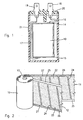
- this invention concerns certain improvements to self-healing capacitors, which are particularly suitable for operating with alternate voltages in the range of a few hundred Volts; preferably, the invention is addressed to capacitors of the aforementioned kind, comprising a cylindrical-shaped capacitive element 10, substantially comprising at least a first and a second metallized dielectric film 11, 12, spirally wound around a central core 13 of insulating material.
- the capacitive element 10 is provided with metal heads 14 and 15 at the two ends, to connect the metal layers of the loops of each dielectric film to one another, as explained further on.
- Each metal head 14, 15 in turn is connected, by an electric wire 16, 17, to an electrical connector 18 and, respectively, 19 of the capacitor, secured to a cover 20.
- the whole assembly is sealed with a resin in an enclosing casing 21.
- the capacitive element 10 comprises two metallized dielectric films 11, 12 each consisting of a strip of a dielectric material, for example a synthetic material such as polypropylene, or other material suitable for the purpose.
- Each dielectric strip 11, 12 on one side surface is provided with a metal layer to form an electrode of the capacitor.
- the metal layer almost entirely covers the surface of the dielectric strip, leaving certain areas or portions of its surface devoid of metal coating; a segmented conformation of the metal layer of this kind is commonly defined as a “comb” or “mosaic” segmentation, depending upon how the segmentation takes place.
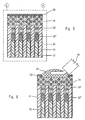
- each dielectric strip 11, 12 is of the comb type in that it comprises a plurality of metal segments 22, 23 separated by strips 24 of non-metallized material, starting from one side edge 25, as shown.
- the metal segments 22, 23 of each strip are electrically connected to one another and to a metallized strip 26 which runs along a side edge opposite the first, by means of metal bridging portions 27 defining "fuses" capable of melting by the Joule effect and electrically isolating the short circuited metal segment or segments, without jeopardising the operation of the capacitor.
- An accurate dimensioning of the fuses is indispensable to ensure the correct functioning of this device for protecting the capacitor.
- one of the dielectric films could be provided with a metallization of continuous type.
- the invention is addressed to an appropriate solution of the capacitive element, comprising the use of dielectric films with a segmented metallization, of comb or mosaic type, as previously defined, in combination with the impregnation of the metal heads and of the closed space between the heads themselves and the axially staggered edges of the loops of the dielectric films, with a dielectric fluid having such a low viscosity, and rapid evaporation, as to allow the assemblage of the capacitors along pre-existing assembling lines.
- the invention is also characterised by a particular manufacturing method comprising vacuum impregnation by a resin of the capacitive element, before its assemblage into a casing of the capacitor.
- low viscosity of the impregnating dielectric fluid is understood to mean a viscosity ranging between 20 and 200 mPa.s, and rapid evaporation is understood to mean the capacity of the dielectric fluid to evaporate, within few seconds, at the welding temperatures of the electric wires to the metal heads.
- the dielectric fluid that can be used for partial impregnation of the capacitive element can be of any type of vegetable or synthetic nature, provided it is suitable for the purpose, capable of rapidly evaporating at the high soldering temperatures of the electric wires to the metal connecting heads, for example within the space of 1 to 3 seconds, thereby ensuring the firm anchoring and a satisfactory electrical contact of the soldering.
- the dielectric fluid can be either of vegetable or synthetic nature.
- a dielectric fluid of vegetable nature suitable for the purpose can be for example colza oil.
- synthetic dielectric fluids can be synthetic silicone and polyol-polyester oils.
- the two dielectric films 11 and 12 are spirally wound, maintaining the side edges axially staggered each others, with the metal layers 22 and 23 disposed between adjacent loops of the two wound-up dielectric films.
- an empty space is formed between adjacent loops of the dielectric films 11 and 12, at each end of the capacitive element 10, comprising the space 30 existing between subsequent loops of a same dielectric film, the dielectric film 11 in figure 3 , and a narrow slit 31 between adjacent loops of the two dielectric films 11 and 12, in correspondence with the non-metallized edge 25.
- Figure 4 shows the same detail as figure 3 , with the addition of a metal head 14, obtained by spraying molten zinc in a per se known way. Since each metal head extends over the entire surface of both ends of the capacitive element 10, as can be clearly seen in figure 4 , between each head 14, 15 and the staggered edges of the loops of the dielectric films a closed space is formed, once again indicated by the reference numbers 30 and 31 in figure 4 .
- the capacitive element 10 thus obtained, would prove to be unsuitable for use in a capacitor, in that the closed space 30, 31 and the space between the wound loops of the dielectric films 11 and 12 retain moisture and air which, due to the reasons previously explained, tend to cause a progressive oxidation and corrosion of the metal layers 22 and 23.
- a partial impregnation under vacuum is carried out, with a dielectric fluid, both of the metal heads 14 and 15 and of the aforementioned closed spaces 30, 31; this impregnation is obtained after having dried the capacitive element 10, by removing under vacuum the moisture and air existing in the capacitive element itself, in that the metal heads 14, 15 have a certain microporosity degree which makes them permeable to air and to liquids, if maintained for a certain length of time immersed into a dielectric fluid, under vacuum conditions.
- a capacitive element 10 provided with the metal heads 14, 15, or several capacitive elements 10 are introduced into a heating and vacuum impregnating chamber 32, which can be connected both to a vacuum source V, such as a vacuum pump, and to a source L of a dielectric fluid of the previously mentioned type.
- a vacuum source V such as a vacuum pump
- a source L of a dielectric fluid of the previously mentioned type The method for vacuum drying and impregnating the capacitive element 10 will be explained further on with reference to the remaining figures from 7 to 10.
- Electric wires can subsequently be soldered onto the heads 14, 15 of the capacitive element 10, suitably pre-impregnated with dielectric fluid, before fitting the capacitive element 10 into the enclosing casing 21 of the capacitor, with wholly conventional pre-existing systems, corresponding to the usual technologies for assembling dry capacitors.
- soldering of the wires 16, 17 can be carried out in a wholly conventional way on a usual assembling line, after vacuum impregnation of the capacitive element 10 with the dielectric fluid.
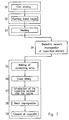
- FIG. 7 shows a simplified block diagram of the entire process for manufacturing the capacitors, comprising the under-vacuum impregnation method of the capacitive elements 10 according to the invention, which will be illustrated in greater detail with reference to the subsequent figures from 8 to 10.
- the manufacturing process of the capacitors according to this invention consists in a first preparing step of the capacitive elements 10, comprising a winding step S1 of the dielectric films 11, 12 as mentioned previously, a second step S2 for forming the metal heads, and a third heating step S3 for the consolidation of the loops of the wound-up dielectric films, in a per se known way.
- the preparation stage of the capacitive element 10, is followed by the under-vacuum impregnation step with a dielectric fluid, indicated as a whole by reference S4 and described in greater detail in the subsequent figures 8 , 9 and 10.
- the final assembling step of the capacitors on usual processing line similar to the one used for dry capacitors, while maintaining all the advantages of this typical technology; in particular, it comprises a welding step S5 for connecting the wires 16, 17 to the metal heads 14, 15 of the capacitive elements 10; the step S6 for fitting the covers 20, the subsequent step S7 for introducing the capacitive element 10 into the casing 21, the step S8 for applying or filling with a resin the space existing between the capacitive element 10 and the casing 21, and the step S9 for closing the capacitors before their final testing.
- the introduction into the autoclave is followed by a heating step S4.1 to bring the capacitive elements 10 to a sufficient temperature to cause their drying.
- step S4.1 Simultaneously to the initial heating step S4.1, a certain degree of vacuum is created into the impregnation chamber 32, to cause suction of the air trapped between the loops of the wound up films, step S4.2.
- the two parameters are maintained at substantially constant values for a sufficient period of time to cause the drying and vacuum de-aeration of the capacitive elements 10.
- the dielectric fluid is fed into the impregnation chamber 32, step S3.
- the dielectric fluid must be fed under vacuum conditions, into the chamber 32 to such a level as to completely submerge all the capacitive elements 10; the conditions of temperature T and of vacuum P during the impregnation step S4.4 must in any case be such as to ensure the total impregnation of the metal heads 14, 15 and of the closed space 30, 31 existing between the heads themselves and the staggered edges of the two dielectric films 11, 12, as shown in the detail of figure 5 .
- step S4.4 Upon completion of the impregnation step S4.4, the vacuum will be gradually reduced and discharged step S4.5, leaving the capacitive elements 10 to cool down, step S4.6.
- the capacitive elements 10, with the heads completely impregnated with dielectric fluid can now be removed from the impregnation chamber 32, and sent on to a subsequent assembling of the capacitors, according to the steps from S5 to S8, along a pre-existing automatic assembling line.
Landscapes
- Engineering & Computer Science (AREA)
- Power Engineering (AREA)
- Manufacturing & Machinery (AREA)
- Microelectronics & Electronic Packaging (AREA)
- Fixed Capacitors And Capacitor Manufacturing Machines (AREA)
- Preventing Corrosion Or Incrustation Of Metals (AREA)
Claims (11)
- Selbstheilender Kondensator für Wechselspannungen des Typs, der ein kapazitives Element (10) umfasst, das zumindest aus einem ersten und einem zweiten spiralförmig gewickelten, metallisierten dielektrischen Film (11, 12) besteht und in dem die Metallschichten der Schleifen jedes dielektrischen Films (11, 12) an jedem Ende des kapazitiven Elements (10) mit einem Metallkopf (14) entsprechend verbunden sind, dadurch gekennzeichnet, dass:die Metallschicht wenigstens eines dielektrischen Films (11, 12) in Metallsegmente oder -abschnitte (22, 23) unterteilt ist, die durch dünne Metallisierungsstreifen (27) verbunden sind;die Schleifen des ersten und des zweiten dielektrischen Films (11, 12) an jedem Ende des kapazitiven Elements (10) entsprechende axial versetzte Kanten besitzen; unddass zwischen jedem Metallkopf (14) und den versetzten Kanten der dielektrischen Filme (11, 12) ein geschlossener Raum (30, 31) vorgesehen ist;wobei jeder Metallkopf (14) und der oben genannte geschlossene Raum (30, 31) unter Vakuum mit einem dielektrischen Fluid mit einer Viskosität im Bereich von 20 bis 200 mPa · s imprägniert sind.
- Kondensator nach Anspruch 1, dadurch gekennzeichnet, dass das dielektrische Fluid für die Imprägnierung des kapazitiven Elements (10) synthetischer Natur ist.
- Kondensator nach Anspruch 2, dadurch gekennzeichnet, dass das synthetische dielektrische Fluid aus Silikon- oder Polyol-Polyester-Öl gewählt ist.
- Kondensator nach Anspruch 1, dadurch gekennzeichnet, dass das dielektrische Fluid für die Imprägnierung des kapazitiven Elements (10) pflanzlicher Natur ist.
- Kondensator nach Anspruch 4, dadurch gekennzeichnet, dass das dielektrische Fluid Rapsöl ist.
- Verfahren für die Herstellung eines kapazitiven Elements (10) für selbstheilende Kondensatoren, wobei das kapazitive Element wenigstens einen ersten und einen zweiten spiralförmig gewundenen metallisierten dielektrischen Film (11, 12) und Metallköpfe (14) umfasst, gekennzeichnet durch die folgenden Schritte:Erhitzen des kapazitiven Elements (10), das in eine Imprägnierungskammer (32) unter Vakuumbedingungen eingeschlossen ist;zuführen einer dielektrischen Flüssigkeit in die Imprägnierungskammer (32);Veranlassen, dass die Metallköpfe (14) und ein geschlossener Raum (30, 31) zwischen jedem Metallkopf (14) und axial versetzten Kanten der Schleifen der dielektrischen Filme (11, 12) mit einem dielektrischen Fluid imprägniert werden, wobei während des Imprägnierungsschrittes kontrollierte Heiz- und Vakuumbedingungen in der Kammer (32) aufrecht erhalten werden;wobei das dielektrische Fluid eine Viskosität im Bereich von 20 bis 200 mPa · s besitzt.
- Verfahren nach Anspruch 6, dadurch gekennzeichnet, dass das dielektrische Fluid synthetischer Natur ist und aus Silikon und Polyol-Polyester-Öl gewählt ist.
- Verfahren nach Anspruch 6, dadurch gekennzeichnet, dass das dielektrische Fluid Rapsöl ist.
- Verfahren nach Anspruch 6, gekennzeichnet durch Vakuumimprägnierung des kapazitiven Elements (10) durch vollständiges Eintauchen in das dielektrische Fluid.
- Verfahren nach Anspruch 6, gekennzeichnet durch Entlüften des kapazitiven Elements (10) bei konstanter Heiztemperatur und unter Vakuumbedingungen, bevor das dielektrische Fluid der Imprägnierungskammer (32) zugeführt wird, und anschließend Aufrechterhalten des Heizens des kapazitiven Elements (10) unter Vakuumbedingungen.
- Kapazitives Element (10), das gemäß dem Verfahren nach einem der Ansprüche 6 bis 10 hergestellt ist, für selbstheilende Wechselspannungskondensatoren, das umfasst:wenigstens einen ersten und einen zweiten metallisierten dielektrischen Film (11, 12), wovon wenigstens einer eine segmentierte Metallisierung (22, 23) besitzt, wobei die dielektrischen Filme (11, 12) spiralförmig gewunden sind und axial versetzte Kanten besitzen; undeinen Metallkopf (14) für die elektrische Verbindung mit den Metallschichten an jedem Ende des kapazitiven Elements (10);wobei jeder Metallkopf (14) und ein geschlossener Raum (30, 31), der zwischen diesem Metallkopf (14) und den versetzten Kanten der dielektrischen Filme (11, 12) vorhanden ist, unter Heiz- und Vakuumbedingungen mit einem dielektrischen Fluid imprägniert werden.
Applications Claiming Priority (1)
| Application Number | Priority Date | Filing Date | Title |
|---|---|---|---|
| IT002040A ITMI20062040A1 (it) | 2006-10-24 | 2006-10-24 | Condensatotre autorigenerabile con sistema anticorrosione e metodo fi fabbricazione |
Publications (2)
| Publication Number | Publication Date |
|---|---|
| EP1916680A1 EP1916680A1 (de) | 2008-04-30 |
| EP1916680B1 true EP1916680B1 (de) | 2012-02-29 |
Family
ID=38983442
Family Applications (1)
| Application Number | Title | Priority Date | Filing Date |
|---|---|---|---|
| EP07017558A Not-in-force EP1916680B1 (de) | 2006-10-24 | 2007-09-07 | Selbstheilender Kondensator mit Korrosionsschutz, kapazitives Element und Verfahren zu seiner Herstellung |
Country Status (3)
| Country | Link |
|---|---|
| EP (1) | EP1916680B1 (de) |
| AT (1) | ATE547797T1 (de) |
| IT (1) | ITMI20062040A1 (de) |
Families Citing this family (2)
| Publication number | Priority date | Publication date | Assignee | Title |
|---|---|---|---|---|
| CN113567770A (zh) * | 2020-04-29 | 2021-10-29 | 优普电子(苏州)有限公司 | 一种金属化薄膜电容器自愈放电测试系统及方法 |
| CN115966401B (zh) * | 2023-01-03 | 2025-06-27 | 苏州昀冢电子科技股份有限公司 | 电容器以及电容器制造方法 |
Family Cites Families (6)
| Publication number | Priority date | Publication date | Assignee | Title |
|---|---|---|---|---|
| US4813116A (en) * | 1981-08-18 | 1989-03-21 | Westinghouse Electric Corp. | Method of making a multi-section power capacitor with all-film dielectric |
| FR2659485A1 (fr) * | 1990-03-09 | 1991-09-13 | Europ Composants Electron | Condensateur a film dielectrique souple metallise et procede de realisation d'un tel condensateur. |
| US5737179A (en) * | 1996-02-07 | 1998-04-07 | Catalina Coatings, Inc. | Metallized film capacitor |
| DE19806586C2 (de) * | 1998-02-17 | 2001-08-16 | Epcos Ag | Metallisierung für selbstheilenden Folienkondensator |
| US6310760B1 (en) * | 2000-03-15 | 2001-10-30 | Sandia Corporation | Adhesive, elastomeric gel impregnating composition |
| JP2005072294A (ja) * | 2003-08-26 | 2005-03-17 | Shizuki Electric Co Inc | 金属化フィルムコンデンサ |
-
2006
- 2006-10-24 IT IT002040A patent/ITMI20062040A1/it unknown
-
2007
- 2007-09-07 AT AT07017558T patent/ATE547797T1/de active
- 2007-09-07 EP EP07017558A patent/EP1916680B1/de not_active Not-in-force
Also Published As
| Publication number | Publication date |
|---|---|
| EP1916680A1 (de) | 2008-04-30 |
| ATE547797T1 (de) | 2012-03-15 |
| ITMI20062040A1 (it) | 2008-04-25 |
Similar Documents
| Publication | Publication Date | Title |
|---|---|---|
| EP3467857B1 (de) | Elektrolytkondensator und verfahren zur herstellung davon | |
| EP1916680B1 (de) | Selbstheilender Kondensator mit Korrosionsschutz, kapazitives Element und Verfahren zu seiner Herstellung | |
| US4635163A (en) | Self-regenerating capacitor protected by athermal circuit-breaker and a process for its manufacture | |
| FI75686C (fi) | Kantbelagd kondensatorelektrod. | |
| EP0328576B1 (de) | Eletrischer kondensator mit verbessertem dielektrischem system | |
| JP6986693B2 (ja) | 電解コンデンサおよびその製造方法 | |
| US5680290A (en) | Capacitor having a fuse and a weak member | |
| WO2002084673A1 (en) | Dielectric fluid | |
| EP3605560B1 (de) | Stromkabel | |
| US5638250A (en) | Capacitor provided with internal protection | |
| US4150419A (en) | Electrical capacitor with a fuse | |
| US3944895A (en) | Plastic capacitors | |
| JP2004535683A (ja) | 電力伝送系統に用いるためのサージ電圧保護装置 | |
| US7027285B2 (en) | Vented Capacitor | |
| Brubaker et al. | Vented Capacitor | |
| Gully | Failure mechanisms in film-based power capacitors | |
| EP0465290B1 (de) | Verfahren zum Herstellen eines Leistungskondensators | |
| KR100210560B1 (ko) | 전력콘덴서 | |
| FI79631C (fi) | Medelst vaermesaekring skyddad sjaelvregenererad kondensator och foerfarande foer dess framstaellning. | |
| JP3307135B2 (ja) | 電解コンデンサの製造方法 | |
| GB1569186A (en) | Electrical roll capacitor with contact-breaking device | |
| WO2017088932A1 (en) | Composite insulation material for an electric power cable, process to manufacture a power cable and a power cable containing the insulation material | |
| RU2597890C1 (ru) | Способ пропитки обмоток электрических машин | |
| Fleming et al. | Chemical action in the windings of high-voltage machines | |
| JPH02257610A (ja) | 液浸コンデンサ |
Legal Events
| Date | Code | Title | Description |
|---|---|---|---|
| PUAI | Public reference made under article 153(3) epc to a published international application that has entered the european phase |
Free format text: ORIGINAL CODE: 0009012 |
|
| AK | Designated contracting states |
Kind code of ref document: A1 Designated state(s): AT BE BG CH CY CZ DE DK EE ES FI FR GB GR HU IE IS IT LI LT LU LV MC MT NL PL PT RO SE SI SK TR |
|
| AX | Request for extension of the european patent |
Extension state: AL BA HR MK RS |
|
| 17P | Request for examination filed |
Effective date: 20080402 |
|
| AKX | Designation fees paid |
Designated state(s): AT BE BG CH CY CZ DE DK EE ES FI FR GB GR HU IE IS IT LI LT LU LV MC MT NL PL PT RO SE SI SK TR |
|
| GRAP | Despatch of communication of intention to grant a patent |
Free format text: ORIGINAL CODE: EPIDOSNIGR1 |
|
| GRAS | Grant fee paid |
Free format text: ORIGINAL CODE: EPIDOSNIGR3 |
|
| GRAA | (expected) grant |
Free format text: ORIGINAL CODE: 0009210 |
|
| AK | Designated contracting states |
Kind code of ref document: B1 Designated state(s): AT BE BG CH CY CZ DE DK EE ES FI FR GB GR HU IE IS IT LI LT LU LV MC MT NL PL PT RO SE SI SK TR |
|
| REG | Reference to a national code |
Ref country code: GB Ref legal event code: FG4D Ref country code: CH Ref legal event code: EP |
|
| REG | Reference to a national code |
Ref country code: AT Ref legal event code: REF Ref document number: 547797 Country of ref document: AT Kind code of ref document: T Effective date: 20120315 |
|
| REG | Reference to a national code |
Ref country code: IE Ref legal event code: FG4D |
|
| REG | Reference to a national code |
Ref country code: DE Ref legal event code: R096 Ref document number: 602007020942 Country of ref document: DE Effective date: 20120426 |
|
| REG | Reference to a national code |
Ref country code: NL Ref legal event code: VDEP Effective date: 20120229 |
|
| LTIE | Lt: invalidation of european patent or patent extension |
Effective date: 20120229 |
|
| PG25 | Lapsed in a contracting state [announced via postgrant information from national office to epo] |
Ref country code: NL Free format text: LAPSE BECAUSE OF FAILURE TO SUBMIT A TRANSLATION OF THE DESCRIPTION OR TO PAY THE FEE WITHIN THE PRESCRIBED TIME-LIMIT Effective date: 20120229 Ref country code: LT Free format text: LAPSE BECAUSE OF FAILURE TO SUBMIT A TRANSLATION OF THE DESCRIPTION OR TO PAY THE FEE WITHIN THE PRESCRIBED TIME-LIMIT Effective date: 20120229 Ref country code: IS Free format text: LAPSE BECAUSE OF FAILURE TO SUBMIT A TRANSLATION OF THE DESCRIPTION OR TO PAY THE FEE WITHIN THE PRESCRIBED TIME-LIMIT Effective date: 20120629 |
|
| PG25 | Lapsed in a contracting state [announced via postgrant information from national office to epo] |
Ref country code: FI Free format text: LAPSE BECAUSE OF FAILURE TO SUBMIT A TRANSLATION OF THE DESCRIPTION OR TO PAY THE FEE WITHIN THE PRESCRIBED TIME-LIMIT Effective date: 20120229 Ref country code: LV Free format text: LAPSE BECAUSE OF FAILURE TO SUBMIT A TRANSLATION OF THE DESCRIPTION OR TO PAY THE FEE WITHIN THE PRESCRIBED TIME-LIMIT Effective date: 20120229 Ref country code: PT Free format text: LAPSE BECAUSE OF FAILURE TO SUBMIT A TRANSLATION OF THE DESCRIPTION OR TO PAY THE FEE WITHIN THE PRESCRIBED TIME-LIMIT Effective date: 20120629 Ref country code: BE Free format text: LAPSE BECAUSE OF FAILURE TO SUBMIT A TRANSLATION OF THE DESCRIPTION OR TO PAY THE FEE WITHIN THE PRESCRIBED TIME-LIMIT Effective date: 20120229 Ref country code: GR Free format text: LAPSE BECAUSE OF FAILURE TO SUBMIT A TRANSLATION OF THE DESCRIPTION OR TO PAY THE FEE WITHIN THE PRESCRIBED TIME-LIMIT Effective date: 20120530 |
|
| REG | Reference to a national code |
Ref country code: AT Ref legal event code: MK05 Ref document number: 547797 Country of ref document: AT Kind code of ref document: T Effective date: 20120229 |
|
| PG25 | Lapsed in a contracting state [announced via postgrant information from national office to epo] |
Ref country code: CY Free format text: LAPSE BECAUSE OF FAILURE TO SUBMIT A TRANSLATION OF THE DESCRIPTION OR TO PAY THE FEE WITHIN THE PRESCRIBED TIME-LIMIT Effective date: 20120229 |
|
| PG25 | Lapsed in a contracting state [announced via postgrant information from national office to epo] |
Ref country code: PL Free format text: LAPSE BECAUSE OF FAILURE TO SUBMIT A TRANSLATION OF THE DESCRIPTION OR TO PAY THE FEE WITHIN THE PRESCRIBED TIME-LIMIT Effective date: 20120229 Ref country code: SE Free format text: LAPSE BECAUSE OF FAILURE TO SUBMIT A TRANSLATION OF THE DESCRIPTION OR TO PAY THE FEE WITHIN THE PRESCRIBED TIME-LIMIT Effective date: 20120229 Ref country code: RO Free format text: LAPSE BECAUSE OF FAILURE TO SUBMIT A TRANSLATION OF THE DESCRIPTION OR TO PAY THE FEE WITHIN THE PRESCRIBED TIME-LIMIT Effective date: 20120229 Ref country code: SI Free format text: LAPSE BECAUSE OF FAILURE TO SUBMIT A TRANSLATION OF THE DESCRIPTION OR TO PAY THE FEE WITHIN THE PRESCRIBED TIME-LIMIT Effective date: 20120229 Ref country code: EE Free format text: LAPSE BECAUSE OF FAILURE TO SUBMIT A TRANSLATION OF THE DESCRIPTION OR TO PAY THE FEE WITHIN THE PRESCRIBED TIME-LIMIT Effective date: 20120229 Ref country code: DK Free format text: LAPSE BECAUSE OF FAILURE TO SUBMIT A TRANSLATION OF THE DESCRIPTION OR TO PAY THE FEE WITHIN THE PRESCRIBED TIME-LIMIT Effective date: 20120229 Ref country code: CZ Free format text: LAPSE BECAUSE OF FAILURE TO SUBMIT A TRANSLATION OF THE DESCRIPTION OR TO PAY THE FEE WITHIN THE PRESCRIBED TIME-LIMIT Effective date: 20120229 |
|
| PG25 | Lapsed in a contracting state [announced via postgrant information from national office to epo] |
Ref country code: SK Free format text: LAPSE BECAUSE OF FAILURE TO SUBMIT A TRANSLATION OF THE DESCRIPTION OR TO PAY THE FEE WITHIN THE PRESCRIBED TIME-LIMIT Effective date: 20120229 |
|
| PLBE | No opposition filed within time limit |
Free format text: ORIGINAL CODE: 0009261 |
|
| STAA | Information on the status of an ep patent application or granted ep patent |
Free format text: STATUS: NO OPPOSITION FILED WITHIN TIME LIMIT |
|
| PG25 | Lapsed in a contracting state [announced via postgrant information from national office to epo] |
Ref country code: AT Free format text: LAPSE BECAUSE OF FAILURE TO SUBMIT A TRANSLATION OF THE DESCRIPTION OR TO PAY THE FEE WITHIN THE PRESCRIBED TIME-LIMIT Effective date: 20120229 |
|
| 26N | No opposition filed |
Effective date: 20121130 |
|
| REG | Reference to a national code |
Ref country code: DE Ref legal event code: R097 Ref document number: 602007020942 Country of ref document: DE Effective date: 20121130 |
|
| PG25 | Lapsed in a contracting state [announced via postgrant information from national office to epo] |
Ref country code: MC Free format text: LAPSE BECAUSE OF NON-PAYMENT OF DUE FEES Effective date: 20120930 Ref country code: ES Free format text: LAPSE BECAUSE OF FAILURE TO SUBMIT A TRANSLATION OF THE DESCRIPTION OR TO PAY THE FEE WITHIN THE PRESCRIBED TIME-LIMIT Effective date: 20120609 |
|
| REG | Reference to a national code |
Ref country code: CH Ref legal event code: PL |
|
| REG | Reference to a national code |
Ref country code: IE Ref legal event code: MM4A |
|
| PG25 | Lapsed in a contracting state [announced via postgrant information from national office to epo] |
Ref country code: LI Free format text: LAPSE BECAUSE OF NON-PAYMENT OF DUE FEES Effective date: 20120930 Ref country code: CH Free format text: LAPSE BECAUSE OF NON-PAYMENT OF DUE FEES Effective date: 20120930 Ref country code: IE Free format text: LAPSE BECAUSE OF NON-PAYMENT OF DUE FEES Effective date: 20120907 Ref country code: BG Free format text: LAPSE BECAUSE OF FAILURE TO SUBMIT A TRANSLATION OF THE DESCRIPTION OR TO PAY THE FEE WITHIN THE PRESCRIBED TIME-LIMIT Effective date: 20120529 |
|
| PG25 | Lapsed in a contracting state [announced via postgrant information from national office to epo] |
Ref country code: MT Free format text: LAPSE BECAUSE OF FAILURE TO SUBMIT A TRANSLATION OF THE DESCRIPTION OR TO PAY THE FEE WITHIN THE PRESCRIBED TIME-LIMIT Effective date: 20120229 |
|
| PG25 | Lapsed in a contracting state [announced via postgrant information from national office to epo] |
Ref country code: TR Free format text: LAPSE BECAUSE OF FAILURE TO SUBMIT A TRANSLATION OF THE DESCRIPTION OR TO PAY THE FEE WITHIN THE PRESCRIBED TIME-LIMIT Effective date: 20120229 |
|
| PG25 | Lapsed in a contracting state [announced via postgrant information from national office to epo] |
Ref country code: LU Free format text: LAPSE BECAUSE OF NON-PAYMENT OF DUE FEES Effective date: 20120907 |
|
| PG25 | Lapsed in a contracting state [announced via postgrant information from national office to epo] |
Ref country code: HU Free format text: LAPSE BECAUSE OF FAILURE TO SUBMIT A TRANSLATION OF THE DESCRIPTION OR TO PAY THE FEE WITHIN THE PRESCRIBED TIME-LIMIT Effective date: 20070907 |
|
| REG | Reference to a national code |
Ref country code: FR Ref legal event code: PLFP Year of fee payment: 10 |
|
| REG | Reference to a national code |
Ref country code: FR Ref legal event code: PLFP Year of fee payment: 11 |
|
| REG | Reference to a national code |
Ref country code: FR Ref legal event code: PLFP Year of fee payment: 12 |
|
| PGFP | Annual fee paid to national office [announced via postgrant information from national office to epo] |
Ref country code: GB Payment date: 20220927 Year of fee payment: 16 Ref country code: DE Payment date: 20220928 Year of fee payment: 16 |
|
| PGFP | Annual fee paid to national office [announced via postgrant information from national office to epo] |
Ref country code: FR Payment date: 20220926 Year of fee payment: 16 |
|
| PGFP | Annual fee paid to national office [announced via postgrant information from national office to epo] |
Ref country code: IT Payment date: 20220923 Year of fee payment: 16 |
|
| P01 | Opt-out of the competence of the unified patent court (upc) registered |
Effective date: 20230527 |
|
| REG | Reference to a national code |
Ref country code: DE Ref legal event code: R119 Ref document number: 602007020942 Country of ref document: DE |
|
| GBPC | Gb: european patent ceased through non-payment of renewal fee |
Effective date: 20230907 |
|
| PG25 | Lapsed in a contracting state [announced via postgrant information from national office to epo] |
Ref country code: GB Free format text: LAPSE BECAUSE OF NON-PAYMENT OF DUE FEES Effective date: 20230907 |
|
| PG25 | Lapsed in a contracting state [announced via postgrant information from national office to epo] |
Ref country code: GB Free format text: LAPSE BECAUSE OF NON-PAYMENT OF DUE FEES Effective date: 20230907 Ref country code: FR Free format text: LAPSE BECAUSE OF NON-PAYMENT OF DUE FEES Effective date: 20230930 Ref country code: DE Free format text: LAPSE BECAUSE OF NON-PAYMENT OF DUE FEES Effective date: 20240403 |
|
| PG25 | Lapsed in a contracting state [announced via postgrant information from national office to epo] |
Ref country code: IT Free format text: LAPSE BECAUSE OF NON-PAYMENT OF DUE FEES Effective date: 20230907 |
|
| PG25 | Lapsed in a contracting state [announced via postgrant information from national office to epo] |
Ref country code: IT Free format text: LAPSE BECAUSE OF NON-PAYMENT OF DUE FEES Effective date: 20230907 |