EP1916662A2 - Information reproducing apparatus - Google Patents
Information reproducing apparatus Download PDFInfo
- Publication number
- EP1916662A2 EP1916662A2 EP07020832A EP07020832A EP1916662A2 EP 1916662 A2 EP1916662 A2 EP 1916662A2 EP 07020832 A EP07020832 A EP 07020832A EP 07020832 A EP07020832 A EP 07020832A EP 1916662 A2 EP1916662 A2 EP 1916662A2
- Authority
- EP
- European Patent Office
- Prior art keywords
- hook portion
- chassis
- front panel
- projecting portion
- engaging
- Prior art date
- Legal status (The legal status is an assumption and is not a legal conclusion. Google has not performed a legal analysis and makes no representation as to the accuracy of the status listed.)
- Granted
Links
- 241000276425 Xiphophorus maculatus Species 0.000 claims abstract description 6
- 239000002184 metal Substances 0.000 claims description 12
- 230000015572 biosynthetic process Effects 0.000 description 5
- 238000010586 diagram Methods 0.000 description 3
- 239000011347 resin Substances 0.000 description 2
- 229920005989 resin Polymers 0.000 description 2
- 238000005452 bending Methods 0.000 description 1
- 230000004048 modification Effects 0.000 description 1
- 238000012986 modification Methods 0.000 description 1
- 230000002787 reinforcement Effects 0.000 description 1
- 230000002087 whitening effect Effects 0.000 description 1
Images



Classifications
-
- G—PHYSICS
- G11—INFORMATION STORAGE
- G11B—INFORMATION STORAGE BASED ON RELATIVE MOVEMENT BETWEEN RECORD CARRIER AND TRANSDUCER
- G11B33/00—Constructional parts, details or accessories not provided for in the other groups of this subclass
- G11B33/02—Cabinets; Cases; Stands; Disposition of apparatus therein or thereon
- G11B33/027—Covers
-
- H—ELECTRICITY
- H05—ELECTRIC TECHNIQUES NOT OTHERWISE PROVIDED FOR
- H05K—PRINTED CIRCUITS; CASINGS OR CONSTRUCTIONAL DETAILS OF ELECTRIC APPARATUS; MANUFACTURE OF ASSEMBLAGES OF ELECTRICAL COMPONENTS
- H05K5/00—Casings, cabinets or drawers for electric apparatus
- H05K5/02—Details
- H05K5/03—Covers
Definitions
- the above hook portion 110 is made up of a platy projecting portion 111 which has an engaging hole 111a into which the engaging pawl 201 is inserted from below, ribs 112a and 112d formed on both ends of the projecting portion 111, and ribs 112b and 112c formed between the ribs 112a and 112d on the both ends of the projecting portion 111 on an upper surface side of the projecting portion 111.
- a thickness of the projecting portion 111 is thin enough to bend.
- the ribs 112 reinforce the projecting portion 111.
- a tip of a bottom surface of the projecting portion 111 is formed in a tapered shape so that the hook portion 110 can be engaged with the engaging pawl 201 easily.
Landscapes
- Engineering & Computer Science (AREA)
- Microelectronics & Electronic Packaging (AREA)
- Casings For Electric Apparatus (AREA)
Abstract
Description
- The present invention relates to an information reproducing apparatus provided with a front panel which is attached to a chassis.
- Conventionally, there is a known front panel which has a configuration shown in FIG. 10 as a front panel of an information reproducing apparatus which can reproduce data such audios and videos stored in a record medium such as DVD. A front panel 100 is attached to a
chassis 200 in the information reproducing apparatus. The front panel 100 has ahook portion 110 which extends inward of the information reproducing apparatus. Thechassis 200 has anengaging pawl 201 with which thehook portion 110 engages. Theengaging pawl 201 projects upward. Thechassis 200 has a topcover supporting portion 202 which is formed by bending thechassis 200 to be one step higher than the area near theengaging pawl 201 to support a top cover (not shown) which covers thechassis 200. - The
above hook portion 110 is made up of aplaty projecting portion 111 which has anengaging hole 111a into which theengaging pawl 201 is inserted from below,ribs portion 111, andribs ribs portion 111 on an upper surface side of the projectingportion 111. A thickness of the projectingportion 111 is thin enough to bend. The ribs 112 reinforce the projectingportion 111. A tip of a bottom surface of the projectingportion 111 is formed in a tapered shape so that thehook portion 110 can be engaged with theengaging pawl 201 easily. - However, in the conventional front panel of the information reproducing apparatus, as shown in FIG. 10, the
hook portion 110 and thechassis 200 are located close to each other when theengaging hole 111a in thehook portion 110 is engaged with theengaging pawl 201, thus it is hard to put in a tip of a finger between them, so that it is hard to detach thehook portion 110 from theengaging pawl 201, and thereby it is hard to detach the front panel 100 from thechassis 200. Moreover, the tip of the bottom surface of the projectingportion 111 is formed in the tapered shape, however, the thickness of the projectingportion 111 is thin enough to bend, thus it is hard to hook the tip of the finger on the tapered tip.
Consequently, it is hard to detach thehook portion 110 from theengaging pawl 201. Moreover, when therib 112a on the left side in FIG. 10 and the topcover supporting portion 202 are located close to each other and also when there is a not gap wide enough to put in the finger between them, it is hard to pinch theribs portion 111 with the tip of the fingers and detach thehook portion 110 from theengaging pawl 201. Consequently, it is hard to detach the front panel 100 from thechassis 200. - An object of the present invention is to provide an information reproducing apparatus provided with a front panel which can be easily detached from a chassis.
- According to a first aspect of the present invention, this object is achieved by an information reproducing apparatus comprising: a chassis which has an engaging pawl which projects upward; and a front panel which is attached to a front surface of the chassis.
- The front panel has a hook portion with which the engaging pawl is engaged.
- The hook portion includes a projecting portion which has an engaging hole into which the engaging pawl is inserted from below, and ribs which are formed on both ends of the projecting portion and between the both ends of the projecting portion on an upper surface side of the projecting portion.
- The information reproducing apparatus is characterised in that the hook portion has a finger hook portion which is provided on an upper end of the rib which is formed between the both ends of the projecting portion and extends in a direction toward both laterals of the projecting portion to hook tips of fingers.
- With the above configuration, in the case where the engaging pawl in the chassis is engaged with the engaging hole in the hook portion on the front panel, the front panel can easily be detached from the chassis when the user hooks the tips of the fingers on the finger hook portion in the hook portion and subsequently pinches and picks up the finger hook portion.
- According to a second aspect of the present invention, this object is achieved by an information reproducing apparatus comprising: a chassis which includes a bottom plate, supporting members which extend perpendicularly from both ends of a front end portion in the bottom plate, and a horizontal plate which is disposed between the supporting members and is supported by the supporting members; and a front panel which is attached to a front surface of the chassis.
- An attaching frame in the chassis to attach the front panel is made up of at least a front end portion in the bottom plate, the supporting members, and the horizontal plate.
- The horizontal plate in the chassis is made up of a sheet metal member which has an engaging pawl which projects upward.
- The front panel has a hook portion which extends horizontally inward of the information reproducing apparatus and with which the engaging pawl is engaged.
- The hook portion includes a platy projecting portion which has an engaging hole into which the engaging pawl is inserted from below, and ribs which are formed on both ends of the projecting portion and between the both ends of the projecting portion on an upper surface side of the projecting portion.
- The information reproducing apparatus is characterised in that the hook portion has a finger hook portion which is provided on an upper end of the rib which is formed between the both ends of the projecting portion, extends in a direction toward both laterals of the projecting portion horizontally, has a thickness substantially the same as a width of the rib to hook tips of fingers, and has a width narrower than that of the projecting portion.
- With the above configuration, in the case where the engaging pawl on the horizontal plate in the chassis is engaged with the engaging hole in the hook portion on the front panel, the front panel can easily be detached from the chassis when the user hooks tips of fingers on the finger hook portion in the hook portion and subsequently pinches and picks up the finger hook portion. Moreover, the finger hook portion is provided on the upper end of the rib which is formed between the both ends of the projecting portion and has the width narrower than the projecting portion, so that the user can pinch the finger hook portion without being interfered by the members which is located close to the lateral of the hook portion. Consequently, the front panel can easily be detached from the chassis. Moreover, the thickness of the finger hook portion is substantially the same as the width of the rib, thus the occurrence of the surface sink on the finger hook portion or the rib during the formation of the front panel can be avoided.
- The present invention will be described below with reference to the annexed drawings. It is to be noted that all the drawings are shown for the purpose of illustrating the technical concept of the present invention or embodiments thereof, wherein:
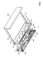
- FIG. 1 is a configuration diagram of an information reproducing apparatus according to a preferred embodiment of the present invention;
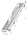
- FIG. 2 is a perspective view of a front surface of a front panel in the information reproducing apparatus in FIG. 1;
- FIG. 3 is a perspective view of a back surface of the front panel in FIG. 2;
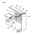
- FIG. 4 is an enlarged perspective view of a portion A framed by a dashed line in FIG. 3;
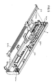
- FIG. 5 is a perspective view of an appearance before engaging a hook portion of the front panel in FIG. 2 with a horizontal plate of a chassis in the information reproducing apparatus in FIG. 1;
- FIG. 6 is a perspective view of an appearance after engaging a hook portion of the front panel in FIG. 2 with the horizontal plate of the chassis in FIG 5;
- FIG. 7 is an enlarged perspective view of a portion B framed by a dashed line in FIG. 6;
- FIG. 8A is a plane view of FIG. 7, FIG. 8B is a front view of FIG. 7, and FIG. 8C is a cross-sectional view along a line C-C' in FIG. 8A;
- FIG. 9 is a front view showing the engagement between the front panel and the horizontal plate in FIG. 6 being released by a user; and
- FIG. 10 is a perspective view of an appearance after engaging a hook portion of a conventional front panel with a chassis in an information reproducing apparatus.
- An information reproducing apparatus according to a preferred embodiment of the present invention is described below with reference to FIGS. 1 to 9. FIG. 1 shows a configuration of an
information reproducing apparatus 1. Theinformation reproducing apparatus 1 has a reproduction function which enables a reproduction of data such as audios and videos which are stored in a record medium and a recording function which enables storage of the data in the record medium. The record medium includes a video tape, CD, DVD, HDD, or the like. Theinformation reproducing apparatus 1 which has the above functions comprises achassis 2, afront panel 3 which is attached to a front surface of thechassis 2, drives (not shown) such as a video drive, a CD drive, a DVD drive, a HDD drive, and so on which are mounted in thechassis 2, and a top cover (not shown) which covers thechassis 2 and the drives. - Next, components of the
information reproducing apparatus 1 are described in detail. Thechassis 2 includes abottom plate 21, supportingmembers end portions front end portion 21a in thebottom plate 21, and ahorizontal plate 24 which is disposed between the supportingmembers members member 22 extends perpendicularly from theend portion 21b which is located on a right side in a direction from thechassis 2 toward thefront panel 3, and the supportingmember 23 extends perpendicularly from theend portion 21c on a left side. Thehorizontal plate 24 is supported by the supportingmember 25 which is located in a substantial center between the supportingmembers horizontal plate 24. - The
bottom plate 21 is made up of a sheet metal member. The sheet metal member which constitutes thebottom plate 21 bends at thefront end portion 21a in thebottom plate 21 in a staircase pattern. Engagingpawls 26 which project from thefront end portion 21a are provided on thefront end portion 21a. The engagingpawls 26 are formed by carrying out a plastic deformation on a portion of thebottom plate 21 through a sheet metal processing so as to engage with thefront panel 3. A cross-sectional surface of the engagingpawl 26 has a triangular shape, for example, and an apex of the triangle is formed to get higher toward an inward of theinformation reproducing apparatus 1. The engagingpawls 26 having such a configuration are respectively provided between the supportingmembers members - The sheet metal member which constitutes the
bottom plate 21 bends at both end portions of thebottom plate 21 in a substantial L-shaped pattern and thereby forms sidewalls 211 and 212. Thesidewall 211 is formed in an end portion which is located on a right side in the direction from thechassis 2 toward thefront panel 3, and thesidewall 212 is formed in an end portion on a left side. An engagingpawl 27 projects from a lateral portion of thesidewall 211. The engagingpawls 27 are formed by carrying out a plastic deformation on a portion of thesidewall 211 through a sheet metal processing, and their shapes are substantially similar to the engagingpawl 26 which is formed on thefront end portion 21a. Moreover, the sheet metal member bends at a back-end of thebottom plate 21 in a substantial L-shaped pattern and thereby forms aback wall 213. - The supporting
members horizontal plate 24 on their upper surface, respectively. In contrast, the supportingmember 23 is made up of a sheet metal member. An upper portion of the supportingmember 23 bends inward of theinformation reproducing apparatus 1, and a lower portion is screwed and fixed to an inside of thesidewall 212 of thebottom plate 21. An engagingpawl 28 projects laterally from an upper side of the fixed portion of the supportingmember 23 to thesidewall 212. The engagingpawl 28 is formed by carrying out a plastic deformation on a portion of the supportingmember 23 through a sheet metal processing, and its shape is substantially similar to the engagingpawl 27 which is formed on thesidewall 211. - The
horizontal plate 24, which is made up of a sheet metal member, has holes to determine its position, and the projections of the supportingmembers horizontal plate 24 is determined according to the layout of the holes. Thehorizontal plate 24 is screwed and fixed to the upper portion of the supportingmember 23 which bends inward and the upper surfaces of the respective supportingmembers horizontal plate 24 has engagingpawls pawls horizontal plate 24 through a sheet metal processing, and their shapes are substantially similar to the engagingpawl 28 which is formed on the supportingmember 23. The engagingpawls horizontal plate 24 to which the supportingmembers - The
front end portion 21a in thebottom plate 21, the supportingmembers horizontal plate 24 make up an attachingframe 2a in thechassis 2 to attach thefront panel 3. As described above, the engagingpawls front end portion 21a and thesidewall 211 in thebottom plate 21 and on the supportingmember 23, respectively, and theengaging pawls horizontal plate 24. Thefront panel 3 includeshook portions hook portions 31 and so on hereinafter) which correspond to the number and the respective positions of the engagingpawls front panel 3 is attached to the attachingframe 2a in thechassis 2 by engaging thehook portions 31 and so on with the engaging pawls 26 and so on in thechassis 2. The components of the attachingframe 2a are not limited to the above. - FIGS. 2 to 4 show the configuration of the
front panel 3. Thefront panel 3 is an injection-molded resin member which is formed in a mold, and includes apanel body 35 and thehook portions 31 and so on which extend from a back surface of thepanel body 35 toward the inward of theinformation reproducing apparatus 1. An upper portion and a lower portion of thepanel body 35 are curved inward of theinformation reproducing apparatus 1, and sidewall portions 35a and 35b are provided in thepanel body 35 to cover openings of both ends of thepanel body 35. The sidewall portion 35a is located in the right side of thepanel body 35 when seeing thepanel body 35 from the back, and the sidewall portion 35b is located in the left side of thepanel body 35 when seeing thepanel body 35 from the back. Various openings and holes are provided in thepanel body 35, and the openings and holes include openings to insert and eject a video tape, CD, and DVD into/ from theinformation reproducing apparatus 1, holes and openings which correspond to operation buttons and operation panels, and holes to connect input-output terminals to theinformation reproducing apparatus 1. - The positions of the
hook portions 31 and so on in thefront panel 3 are specifically described hereinafter. Thehook portions panel body 35. Thehook portion 31 is provided in a lower surface of the curved portion in the lower portion of thepanel body 35. Thehook portion 32 is provided in the right end of thepanel body 35 when seeing thepanel body 35 from the back, and thehook portion 33 is provided in the left end of thepanel body 35 when seeing thepanel body 35 from the back. Thehook portions 31 and so on correspond to the number and the positions of the engaging pawls 26 and so on in the chassis 2 (not shown in FIGS. 2 to 4), respectively. The positions of thehook portions 31 and so on are not limited to the above. - Next, a shape of the
hook portions 31 and so on is described. Thehook portions 31 and so on are platy projecting portions which include engaging holes in which the engaging pawls 26 and so on in thechassis 2 are inserted when thefront panel 3 engages with thechassis 2, respectively. In these platy projecting portions, thehook portions hook portions hook portion 34a in thehook portions 31 and so on is described in detail hereinafter. - The
hook portion 34a includes a projectingportion 342 which extends inward of theinformation reproducing apparatus 1 horizontally and has anengaging hole 341, fourribs portion 342 and remaining two are formed between the both ends of the projectingportion 342 on an upper surface side of the projectingportion 342, and afinger hook portion 344 which is provided on an upper end of onerib 343b which is formed between the both ends of the projectingportion 342 and extends in a direction toward both laterals of the projectingportion 342 horizontally to hook tips of fingers. The projectingportion 342, the ribs 343, and thefinger hook portion 344 are formed to be integral with each other. A portion of the projectingportion 342 is cut off to let out a projection on the upper surface of the supportingmember 22 which is inserted into the hole in thehorizontal plate 24 to determine the position of thehorizontal plate 24 and also to let out a screw which fixes thehorizontal plate 24 on the supportingmember 22. A tip of a bottom surface of the projectingportion 342 is formed in a tapered shape. The ribs 343 reinforce the projectingportion 342. - The
finger hook portion 344 is provided on the rib 343 which is closer to a center of the projectingportion 342 in a width direction in the two ribs 343 which are formed between the both ends of the projectingportion 342. Thefinger hook portion 344 is formed on a portion of the upper end of the rib 343 in continuity. Thefinger hook portion 344 is substantially stable in width, and the width of thefinger hook portion 344 is smaller than a width of the projectingportion 342, and its thickness is substantially the same as the width of the rib 343. Moreover, thefinger hook portion 344 is located between the upper surface and the lower surface of the upper end of the curved portion in the upper portion of thepanel body 35 in a height direction. The engaginghole 341 goes through the projectingportion 342 and the rib 343 on which thefinger hook portion 344 are not provided in the two ribs 343 which are formed between the both ends of the projectingportion 342. - According to the above configuration, the
finger hook portion 344 extends horizontally, so that it is easy to hook the fingers. Moreover, thefinger hook portion 344 is integrally formed along the rib 343, so that a strong force is not necessary to remove the mold during the production of thefront panel 3. Consequently, whitening does not occur on thefront panel 3 due to the formation of thefinger hook portion 344. Thefinger hook portion 344 is formed on the upper end of the rib 343 to be integral with the rib 343 and is located between the upper surface and the lower surface of the upper end of the curved portion in the upper portion of thepanel body 35 in the height direction, so that it is also easy to make the mold of thefront panel 3 which has thefinger hook portion 344. Moreover, the thickness of thefinger hook portion 344 and the width of therib rib 343a to 343d and thefinger hook portion 344 itself due to the formation of thefinger hook portion 344 during the production of thefront panel 3. Furthermore, the openings, the holes, and so on are not necessary when thefinger hook portion 344 is formed, so that a weld line does not occur on thefront panel 3 due to the formation of thefinger hook portion 344. - Besides, the shape of the
finger hook portion 344 is not limited to the above, however, any shape is applicable as long as it has a shape or a size large enough to be hooked by the fingers. Thefinger hook portion 344 may also be formed on the whole upper end of therib 343b in continuity instead of on the portion of the upper end of therib 343b in continuity. When thefinger hook portion 344 is formed on the whole upper end of therib 343b in continuity, thefinger hook portion 344 may extend from the back surface of thepanel body 35 together with therib 343b. When thefinger hook portion 344 is formed in this manner, the width of therib 343b is smaller than the thickness of thepanel body 35, and the thickness of thefinger hook portion 344 is substantially the same as the width of therib 343b, thus the occurrence of the surface sink on the surface of thepanel body 35 due to the formation of thefinger hook portion 344 can be avoided. - FIGS. 5, 6, 7, 8A, 8B, and 8C show appearances before and after the
hook portions hook portions 34a and so on" hereinafter) on thefront panel 3 engage with the engagingpawls engaging pawls 29a and so on" hereinafter) which are provided on thehorizontal plate 24 in thechassis 2. In these diagrams, thebottom plate 21 and the supportingmembers chassis 2 are omitted. Thehorizontal plate 24 has a topcover supporting portion 24a which is bended to be one step higher than the area near the engagingpawl 29a. - The
hook portions 34a and so on are located in the positions to correspond to theengaging pawls 29a and so on in thehorizontal plate 24, respectively. When thefront panel 3 engages with thechassis 2, thehook portions 34a and so on are disposed on the upper side of theengaging pawls 29a and so on. The engagement between thehook portion 34a and the engagingpawl 29a is described in detail hereinafter. - A cross-sectional surface of the engaging
pawl 29a which engages with thehook portion 34a has a triangular shape, for example, and an apex of the triangle is formed to get higher in height from an a portion closer to thefront panel 3 toward the inward of theinformation reproducing apparatus 1. When thefront panel 3 engages with thechassis 2, the bottom surface of the projectingportion 342 has a direct contact with the engagingpawl 29a and has a slide starting from its tip to the engagingpawl 29a. The tip of the bottom surface of the projectingportion 342 is formed in the tapered shape, and in the engagingpawl 29a, the portion closer to thefront panel 3 is lowest in height, and the engagingpawl 29a becomes higher gradually as it gets closer to the inward of theinformation reproducing apparatus 1, so that thehook portion 34a can easily be attached to the engagingpawl 29a while contacting the engagingpawl 29a. As the portion which has a direct contact with the engagingpawl 29a in the projectingportion 342 moves toward thepanel body 35, the projectingportion 342 bends upward. Subsequently, the engagingpawl 29a is inserted into the engaginghole 341 in the projectingportion 342 from below. In this manner, the projectingportion 342 and the engagingpawl 29a engage with each other. - When the projecting
portion 342 and the engagingpawl 29a engage with each other, the projectingportion 342 and the topcover supporting portion 24a are located close to each other, and the topcover supporting portion 24a and thefront panel body 35 are located close to each other, so that it is hard to put the finger in spaces surrounded by them. Moreover, the projectingportion 342 and thehorizontal plate 24 are close to each other, so that it is hard to put in the finger between the projectingportion 342 and thehorizontal plate 24. The tip of the bottom surface of the projectingportion 342 is formed in the tapered shape, however, the projectingportion 342 is thin enough to bend, so that even the tapered tip of the bottom surface of the projectingportion 342 is not of so much help to put in the finger between the tip of the projectingportion 342 and thehorizontal plate 24. - FIG. 9 shows an appearance of the
front panel 3 and thehorizontal plate 24 in thechassis 2 whose engagement is released by a user, and more particularly, an appearance of thehook portion 34a in thefront panel 3 and the engagingpawl 29a on thehorizontal plate 24 whose engagement is released. - In the present preferred embodiment, the
finger hook portion 344 is provided on the upper end of the rib 343, so that when the user hooks tips of fingers F on thefinger hook portion 344 and subsequently pinches and picks up the right side and the left side of thefinger hook portion 344, the engagement between thehook portion 34a and the engagingpawl 29a can easily be released. Consequently, thefront panel 3 can easily be detached from thechassis 2. Moreover, thefinger hook portion 344 is provided on the upper end of therib 343b which is formed between the both ends of the projectingportion 342 and has the width narrower than the projectingportion 342, so that the user can pinch thefinger hook portion 344 without being interfered by the members such as the topcover supporting portion 24a, for example, which is located close to the lateral of thehook portion 34a. Consequently, thefront panel 3 can easily be detached from thechassis 2. - The present invention is not limited to the composition of the preferred embodiment described above, however, various modification are applicable in accordance with the intended use. For example, the number of the engaging
pawls horizontal plate 24 is not limited to the number of the engaging pawls shown in the diagrams, however, any number of the engaging pawls is applicable. Moreover, a panel which has a configuration similar to thefront panel 3 can be attached not only to the front surface of theinformation reproducing apparatus 1 but also to the side surface or the back surface of theinformation reproducing apparatus 1. Furthermore, thehook portions 34a and so on can be provided not only on the upper portion of thepanel body 35 but also on the lower portion of thepanel body 35, the sidewall portions 35a or 35b, or on the area near the lower portion of thepanel body 35. - This application is based on
Japanese utility model application 2006-8703 filed October 25, 2006
Claims (4)
- An information reproducing apparatus (1) comprising:a chassis (2) which has an engaging pawl (29a) which projects upward; anda front panel (3) which is attached to a front surface of the chassis (2),wherein the front panel (3) has a hook portion (34a) with which the engaging pawl (29a) is engaged, and
wherein the hook portion (34a) includes
a projecting portion (342) which has an engaging hole (341) into which the engaging pawl (29a) is inserted from below, and
ribs (343a, 343b, 343c, 343d) which are formed on both ends of the projecting portion (342) and between the both ends of the projecting portion (342) on an upper surface side of the projecting portion (342),
characterised in that the hook portion (34a) has a finger hook portion (344) which is provided on an upper end of the rib (343b) which is formed between the both ends of the projecting portion (342) and extends in a direction toward both laterals of the projecting portion (342) to hook tips of fingers. - The information reproducing apparatus (1) according to claim 1,
wherein in the case where the engaging pawl (29a) in the chassis (2) is engaged with the engaging hole (341) in the hook portion (34a) on the front panel (3), the front panel (3) is detached from the chassis (2) when a user hooks tips of fingers on a finger hook portion (344) in the hook portion (34a) and subsequently pinches and picks up the finger hook portion (344). - The information reproducing apparatus (1) comprising:a chassis (2) which includes a bottom plate (21), supporting members (22, 23, 25) which extend perpendicularly from both ends of a front end portion in the bottom plate (21), and a horizontal plate (24) which is disposed between the supporting members (22, 23, 25) and is supported by the supporting members (22, 23, 25); anda front panel (3) which is attached to a front surface of the chassis (2),wherein an attaching frame in the chassis (2) to attach the front panel (3) is made up of at least a front end portion in the bottom plate (21), the supporting members (22, 23, 25), and the horizontal plate (24),
wherein the horizontal plate (24) in the chassis (2) is made up of a sheet metal member which has an engaging pawl (29a) which projects upward,
wherein the front panel (3) has a hook portion (34a) which extends horizontally inward of the information reproducing apparatus (1) and with which the engaging pawl (29a) is engaged, and
wherein the hook portion (34a) includes
a platy projecting portion (342) which has an engaging hole (341) into which the engaging pawl (29a) is inserted from below, and
ribs (343a, 343b, 343c, 343d) which are formed on both ends of the projecting portion (342) and between the both ends of the projecting portion (342) on an upper surface side of the projecting portion (342),
characterised in that the hook portion (34a) has a finger hook portion (344) which is provided on an upper end of the rib (343b) which is formed between the both ends of the projecting portion (342), extends in a direction toward both laterals of the projecting portion (342) horizontally, has a thickness substantially the same as a width of the rib (343b) to hook tips of fingers, and has a width narrower than that of the projecting portion (342). - The information reproducing apparatus (1) according to claim 3,
wherein in the case where the engaging pawl (29a) on the horizontal plate (24) in the chassis (2) is engaged with the engaging hole (341) in the hook portion (34a) on the front panel (3), the front panel (3) is detached from the chassis (2) when a user hooks tips of fingers on a finger hook portion (344) in the hook portion (34a) and subsequently pinches and picks up the finger hook portion (344).
Applications Claiming Priority (1)
| Application Number | Priority Date | Filing Date | Title |
|---|---|---|---|
| JP2006008703U JP3128410U (en) | 2006-10-25 | 2006-10-25 | Front panel and information reproducing apparatus having the same |
Publications (3)
| Publication Number | Publication Date |
|---|---|
| EP1916662A2 true EP1916662A2 (en) | 2008-04-30 |
| EP1916662A3 EP1916662A3 (en) | 2010-01-06 |
| EP1916662B1 EP1916662B1 (en) | 2011-07-13 |
Family
ID=38890259
Family Applications (1)
| Application Number | Title | Priority Date | Filing Date |
|---|---|---|---|
| EP20070020832 Not-in-force EP1916662B1 (en) | 2006-10-25 | 2007-10-24 | Information reproducing apparatus |
Country Status (2)
| Country | Link |
|---|---|
| EP (1) | EP1916662B1 (en) |
| JP (1) | JP3128410U (en) |
Families Citing this family (1)
| Publication number | Priority date | Publication date | Assignee | Title |
|---|---|---|---|---|
| JP5515805B2 (en) * | 2010-02-03 | 2014-06-11 | 船井電機株式会社 | Electronics |
Citations (1)
| Publication number | Priority date | Publication date | Assignee | Title |
|---|---|---|---|---|
| EP1619684A1 (en) | 2004-07-21 | 2006-01-25 | Samsung Electronics Co., Ltd. | Data recording/reproducing apparatus |
Family Cites Families (2)
| Publication number | Priority date | Publication date | Assignee | Title |
|---|---|---|---|---|
| US5301178A (en) * | 1990-02-22 | 1994-04-05 | Olypus Optical Co., Ltd. | Drive unit for optical memory device with portion of drive means mounted outside a sealing means |
| US7199310B2 (en) * | 2004-08-23 | 2007-04-03 | Tortured Path- EMI Solutions LLC | Electromagnetic interference shielding structures for computer hard-drive enclosures |
-
2006
- 2006-10-25 JP JP2006008703U patent/JP3128410U/en not_active Expired - Fee Related
-
2007
- 2007-10-24 EP EP20070020832 patent/EP1916662B1/en not_active Not-in-force
Patent Citations (1)
| Publication number | Priority date | Publication date | Assignee | Title |
|---|---|---|---|---|
| EP1619684A1 (en) | 2004-07-21 | 2006-01-25 | Samsung Electronics Co., Ltd. | Data recording/reproducing apparatus |
Also Published As
| Publication number | Publication date |
|---|---|
| JP3128410U (en) | 2007-01-11 |
| EP1916662B1 (en) | 2011-07-13 |
| EP1916662A3 (en) | 2010-01-06 |
Similar Documents
| Publication | Publication Date | Title |
|---|---|---|
| CN100386817C (en) | Disc device | |
| CN200983121Y (en) | Fixing set for data accessor | |
| US20110051350A1 (en) | Storage device module and screw mounting structure of the same | |
| JP2010068388A (en) | Cabinet of electronic equipment | |
| CN100511468C (en) | thin optical drive | |
| EP1916662B1 (en) | Information reproducing apparatus | |
| US7802269B2 (en) | Electronic apparatus | |
| CN201115148Y (en) | Fixing assembly | |
| JP3129253U (en) | Front panel and information reproducing apparatus having the same | |
| US7430751B2 (en) | Data recording/reproducing apparatus with an improved structure for securely supporting a front panel | |
| JP2009294862A (en) | Electronic apparatus | |
| US20110191793A1 (en) | Optical disc drive | |
| CN2493967Y (en) | Fastener for information access device | |
| US6004143A (en) | Mounting structure of I/O connector in magnetic disk drive | |
| US20060156930A1 (en) | Fixing mechanism for storage device | |
| US20070177337A1 (en) | Electronic device | |
| US8424029B2 (en) | Optical disc device | |
| JP3128408U (en) | Information playback device | |
| JP2012248751A (en) | Chassis and chassis mounting structure | |
| CN2636373Y (en) | Improved structure of combination of appearance stamping parts and base | |
| JP2012146361A (en) | Optical dick device | |
| JP3674646B2 (en) | Slide mechanism | |
| CN2809796Y (en) | A CD player | |
| KR100734265B1 (en) | Hard disk drive bays and hard disk drive mounting structures | |
| TWI383728B (en) | Machine case |
Legal Events
| Date | Code | Title | Description |
|---|---|---|---|
| PUAI | Public reference made under article 153(3) epc to a published international application that has entered the european phase |
Free format text: ORIGINAL CODE: 0009012 |
|
| AK | Designated contracting states |
Kind code of ref document: A2 Designated state(s): AT BE BG CH CY CZ DE DK EE ES FI FR GB GR HU IE IS IT LI LT LU LV MC MT NL PL PT RO SE SI SK TR |
|
| AX | Request for extension of the european patent |
Extension state: AL BA HR MK RS |
|
| PUAL | Search report despatched |
Free format text: ORIGINAL CODE: 0009013 |
|
| AK | Designated contracting states |
Kind code of ref document: A3 Designated state(s): AT BE BG CH CY CZ DE DK EE ES FI FR GB GR HU IE IS IT LI LT LU LV MC MT NL PL PT RO SE SI SK TR |
|
| AX | Request for extension of the european patent |
Extension state: AL BA HR MK RS |
|
| 17P | Request for examination filed |
Effective date: 20100623 |
|
| AKX | Designation fees paid |
Designated state(s): DE FR GB |
|
| GRAP | Despatch of communication of intention to grant a patent |
Free format text: ORIGINAL CODE: EPIDOSNIGR1 |
|
| RIC1 | Information provided on ipc code assigned before grant |
Ipc: G11B 33/02 20060101AFI20101208BHEP |
|
| GRAS | Grant fee paid |
Free format text: ORIGINAL CODE: EPIDOSNIGR3 |
|
| GRAA | (expected) grant |
Free format text: ORIGINAL CODE: 0009210 |
|
| AK | Designated contracting states |
Kind code of ref document: B1 Designated state(s): DE FR GB |
|
| REG | Reference to a national code |
Ref country code: GB Ref legal event code: FG4D |
|
| REG | Reference to a national code |
Ref country code: DE Ref legal event code: R096 Ref document number: 602007015723 Country of ref document: DE Effective date: 20110908 |
|
| PLBE | No opposition filed within time limit |
Free format text: ORIGINAL CODE: 0009261 |
|
| STAA | Information on the status of an ep patent application or granted ep patent |
Free format text: STATUS: NO OPPOSITION FILED WITHIN TIME LIMIT |
|
| 26N | No opposition filed |
Effective date: 20120416 |
|
| REG | Reference to a national code |
Ref country code: DE Ref legal event code: R097 Ref document number: 602007015723 Country of ref document: DE Effective date: 20120416 |
|
| PGFP | Annual fee paid to national office [announced via postgrant information from national office to epo] |
Ref country code: FR Payment date: 20141008 Year of fee payment: 8 Ref country code: GB Payment date: 20141022 Year of fee payment: 8 Ref country code: DE Payment date: 20141023 Year of fee payment: 8 |
|
| REG | Reference to a national code |
Ref country code: DE Ref legal event code: R119 Ref document number: 602007015723 Country of ref document: DE |
|
| GBPC | Gb: european patent ceased through non-payment of renewal fee |
Effective date: 20151024 |
|
| PG25 | Lapsed in a contracting state [announced via postgrant information from national office to epo] |
Ref country code: GB Free format text: LAPSE BECAUSE OF NON-PAYMENT OF DUE FEES Effective date: 20151024 Ref country code: DE Free format text: LAPSE BECAUSE OF NON-PAYMENT OF DUE FEES Effective date: 20160503 |
|
| REG | Reference to a national code |
Ref country code: FR Ref legal event code: ST Effective date: 20160630 |
|
| PG25 | Lapsed in a contracting state [announced via postgrant information from national office to epo] |
Ref country code: FR Free format text: LAPSE BECAUSE OF NON-PAYMENT OF DUE FEES Effective date: 20151102 |