EP1916636A1 - Automated teller machine - Google Patents
Automated teller machine Download PDFInfo
- Publication number
- EP1916636A1 EP1916636A1 EP07253986A EP07253986A EP1916636A1 EP 1916636 A1 EP1916636 A1 EP 1916636A1 EP 07253986 A EP07253986 A EP 07253986A EP 07253986 A EP07253986 A EP 07253986A EP 1916636 A1 EP1916636 A1 EP 1916636A1
- Authority
- EP
- European Patent Office
- Prior art keywords
- atm
- head unit
- security enclosure
- wall
- media
- Prior art date
- Legal status (The legal status is an assumption and is not a legal conclusion. Google has not performed a legal analysis and makes no representation as to the accuracy of the status listed.)
- Withdrawn
Links
- 230000003993 interaction Effects 0.000 claims abstract description 4
- 230000015654 memory Effects 0.000 description 3
- 238000012986 modification Methods 0.000 description 3
- 230000004048 modification Effects 0.000 description 3
- 238000010586 diagram Methods 0.000 description 2
- 238000010276 construction Methods 0.000 description 1
- 238000004806 packaging method and process Methods 0.000 description 1
- 238000006467 substitution reaction Methods 0.000 description 1
Images

Classifications
-
- G—PHYSICS
- G07—CHECKING-DEVICES
- G07F—COIN-FREED OR LIKE APPARATUS
- G07F19/00—Complete banking systems; Coded card-freed arrangements adapted for dispensing or receiving monies or the like and posting such transactions to existing accounts, e.g. automatic teller machines
- G07F19/20—Automatic teller machines [ATMs]
- G07F19/205—Housing aspects of ATMs
-
- G—PHYSICS
- G07—CHECKING-DEVICES
- G07F—COIN-FREED OR LIKE APPARATUS
- G07F19/00—Complete banking systems; Coded card-freed arrangements adapted for dispensing or receiving monies or the like and posting such transactions to existing accounts, e.g. automatic teller machines
- G07F19/20—Automatic teller machines [ATMs]
Definitions
- the present invention relates to an Automated Teller Machine (ATM).
- ATM Automated Teller Machine
- the invention looks at a revolutionary re-think of the way in which a user interface of an ATM is presented to users.
- an ATM has taken up a significant floor area of a financial institution or outdoor space.
- through-the-wall ATMs there has been a need for significant building work including cutting a hole in a wall of approximately the dimensions of the present user interface. This increases ATM implementation costs and times.
- an automated teller machine comprising: an ATM head unit in the form of a housing within which are housed user interface components of an ATM; a security enclosure within which is located an ATM media dispenser; wherein the security enclosure and the head unit are discrete physically separate units, which are coupled so that media from the security enclosure can be dispensed to a user through interaction with the head unit, when in use.
- the media dispenser is a cash dispenser.
- the security enclosure further contains a media acceptor.
- the user interface components include a card reader, a key pad, a cash dispenser slot, a display with FDKs, and a receipt printer.
- the head unit may not contain all of these components.
- the head unit is arranged to operate at low voltage, most preferably 24V.
- the ATM is a through-the-wall ATM, wherein the head unit is arranged to be hung on one side of a wall, in use, and the security enclosure is arranged to be located on the opposite side of the wall, the units being coupled by a cash transit path through an aperture in the wall.
- the ATM is arranged to be front opening for repair or replenishment.
- the ATM includes means for wireless communication between the head unit and the security enclosure.
- an automated teller machine comprising: an ATM head unit in the form of a housing within which are housed user interface components of an ATM, including; a card reader, a key pad, a cash dispenser slot, a display with FDKs, and a receipt printer; a security enclosure within which is located an ATM media dispenser; wherein the security enclosure and the head unit are discrete physically separate units , which are coupled so that media from the security enclosure can be dispensed to a user through interaction with the head unit, when in use.
- ATM automated teller machine
- the present invention is directed to an ATM.
- the specific construction of the ATM may vary.
- An ATM head unit 10 embodying the present invention is illustrated in Figs. 1 and 2.
- the ATM includes a head unit 10 comprises a user interface in the form of a 5 front panel 12.
- the front panel 12 includes a card reader 60, a key pad 16, a cash dispenser slot 18, a display 20, and a receipt printer 22.
- the card reader 60 has a card entry slot through which a customer 24 can insert a user identification card 26 at the commencement of a transaction to be conducted by the customer.
- the cash dispenser has a cash slot 18 through which cash currency notes stored inside the security enclosure of the ATM can be delivered to the customer 24 during the transaction.
- the receipt printer 22 has a receipt slot through which a receipt of the transaction is delivered to the customer 24 at termination of the transaction.
- the card reader When the customer 24 inserts the user identification card 26 into the card entry slot of the card reader 60, the card reader reads data contained on the card. The customer 24 is then prompted on the display 20 to enter a personal identification number (PIN) via the key pad 16. After the correct PIN is entered, menus are displayed on the display 20 to enable the customer 24 to carry out the desired transaction. After the transaction is completed, the receipt printer 22 prints a receipt of the transaction and delivers the receipt through the slot of the receipt printer 22 to the customer 24.
- PIN personal identification number
- the ATM 10 further comprises a controller unit 30 which communicates with components of the front panel 12.
- the controller unit 30 includes a microcomputer 32 and a memory 34 connected via bus line 36 to the microcomputer 32.
- the microcomputer 32 receives input signals on lines 31, 33 from the card reader 60 and the key pad 16, respectively, and provides output signals on lines 35, 37, 39 to the cash dispenser 18, the display 20, and the receipt printer 22, respectively, to control the amount of cash dispensed by the cash dispensed by the cash dispenser 18, the information displayed on the display 20, and the information printed by the receipt printer 22.
- the memory 34 may be non-volatile RAM. Suitable microcomputers and memories are readily available in the marketplace. Their structure and operation are well known and, therefore, will not be described.
- the microcomputer 32 communicates via a line with a central terminal located remotely from the ATM.
- the line is a proprietary network owned by the financial institution which operates the ATM.
- the remote central terminal may be located at the headquarters of the financial institution.
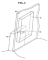
- Fig. 3 illustrates a through-the -wall ATM in accordance with the present invention in place and ready for use.
- the ATM comprises a head unit 40 in the form of a housing within which are housed user interface components of an ATM. These component include all of the components necessary to operate an ATM including a card reader, a key pad, a cash dispenser slot, a display with FDKs, and a receipt printer.
- the ATM further includes a security enclosure 42 within which is located an ATM media dispenser.
- the dispenser is a standard dispenser in which the transport path is arranged to provide picked notes to the user through the head unit 10. This is achieved by providing a small aperture 42 from the security enclosure 40 to the dispenser slot 18 of the head unit 10.
- the units 10, 40 are discrete physically separate units, which are coupled as detailed above.
- the ATM can be arranged to dispense media other than cash, such as travel tickets and the like.
- the ATM can be arranged to accept media if the security enclosure further contains a media acceptor.
- the ATM head unit 10 is arranged to operate at low voltage normally 24V.
- the ATM can be a lobby ATM, a drive through ATM or a through-the-wall ATM.
- the head unit 10 is arranged to be hung on one side of a wall 44, in use, and the security enclosure 40 is arranged to be located on the opposite side of the wall 44, as illustrated in Fig. 3.
- Communication between the units 10, 40 is achieved because the units 10, 40 include means for wireless communication.
- the units can be linked via wires if required.
- the ATM head unit 10 is arranged to be front opening for repair or replenishment.
Landscapes
- Business, Economics & Management (AREA)
- Accounting & Taxation (AREA)
- Finance (AREA)
- Physics & Mathematics (AREA)
- General Physics & Mathematics (AREA)
- Financial Or Insurance-Related Operations Such As Payment And Settlement (AREA)
- Control Of Vending Devices And Auxiliary Devices For Vending Devices (AREA)
- Data Exchanges In Wide-Area Networks (AREA)
Abstract
Description
- The present invention relates to an Automated Teller Machine (ATM).
- There are a number of issues with current ATM designs including product packaging, cost points, and product variants. By providing one low cost assembly for through-the-wall, in-lobby, and free standing ATMs this invention addresses those issues.
- In addition, the invention looks at a revolutionary re-think of the way in which a user interface of an ATM is presented to users. In the past an ATM has taken up a significant floor area of a financial institution or outdoor space. Also, in through-the-wall ATMs there has been a need for significant building work including cutting a hole in a wall of approximately the dimensions of the present user interface. This increases ATM implementation costs and times.
- It is an object of the present invention to provide an ATM which addresses as least some of the problems detailed above.
- In accordance with one aspect of the present invention there is provided an automated teller machine (ATM) comprising: an ATM head unit in the form of a housing within which are housed user interface components of an ATM; a security enclosure within which is located an ATM media dispenser; wherein the security enclosure and the head unit are discrete physically separate units, which are coupled so that media from the security enclosure can be dispensed to a user through interaction with the head unit, when in use.
- Preferably, the media dispenser is a cash dispenser.
- In one embodiment the security enclosure further contains a media acceptor.
- Preferably the user interface components include a card reader, a key pad, a cash dispenser slot, a display with FDKs, and a receipt printer. However, according to the embodiment the head unit may not contain all of these components.
- Preferably, the head unit is arranged to operate at low voltage, most preferably 24V.
- In one embodiment the ATM is a through-the-wall ATM, wherein the head unit is arranged to be hung on one side of a wall, in use, and the security enclosure is arranged to be located on the opposite side of the wall, the units being coupled by a cash transit path through an aperture in the wall. Preferably, the ATM is arranged to be front opening for repair or replenishment.
- Preferably, the ATM includes means for wireless communication between the head unit and the security enclosure.
- According to a second aspect of the present invention there is provided an automated teller machine (ATM) comprising: an ATM head unit in the form of a housing within which are housed user interface components of an ATM, including; a card reader, a key pad, a cash dispenser slot, a display with FDKs, and a receipt printer; a security enclosure within which is located an ATM media dispenser; wherein the security enclosure and the head unit are discrete physically separate units , which are coupled so that media from the security enclosure can be dispensed to a user through interaction with the head unit, when in use.
- Embodiments of the present invention will now be described, by way of example, with reference to the accompanying drawings, in which:
- Fig. 1 is a perspective view of a head unit of an ATM in accordance with an embodiment of the preset invention;
- Fig. 2 is a block diagram representation of the head unit of Fig. 1;
- Fig. 3 is perspective diagram of an ATM in accordance with an embodiment of the present invention arranged with the head and security enclosures on opposite sides of a wall.
- The present invention is directed to an ATM. The specific construction of the ATM may vary. An
ATM head unit 10 embodying the present invention is illustrated in Figs. 1 and 2. - The ATM includes a
head unit 10 comprises a user interface in the form of a 5front panel 12. Thefront panel 12 includes acard reader 60, akey pad 16, acash dispenser slot 18, adisplay 20, and areceipt printer 22. As particularly shown in Fig. 1, thecard reader 60 has a card entry slot through which acustomer 24 can insert auser identification card 26 at the commencement of a transaction to be conducted by the customer. The cash dispenser has acash slot 18 through which cash currency notes stored inside the security enclosure of the ATM can be delivered to thecustomer 24 during the transaction. Thereceipt printer 22 has a receipt slot through which a receipt of the transaction is delivered to thecustomer 24 at termination of the transaction. - When the
customer 24 inserts theuser identification card 26 into the card entry slot of thecard reader 60, the card reader reads data contained on the card. Thecustomer 24 is then prompted on thedisplay 20 to enter a personal identification number (PIN) via thekey pad 16. After the correct PIN is entered, menus are displayed on thedisplay 20 to enable thecustomer 24 to carry out the desired transaction. After the transaction is completed, thereceipt printer 22 prints a receipt of the transaction and delivers the receipt through the slot of thereceipt printer 22 to thecustomer 24. - Referring particularly to Fig. 2, the
ATM 10 further comprises acontroller unit 30 which communicates with components of thefront panel 12. Thecontroller unit 30 includes amicrocomputer 32 and amemory 34 connected viabus line 36 to themicrocomputer 32. Themicrocomputer 32 receives input signals onlines card reader 60 and thekey pad 16, respectively, and provides output signals onlines cash dispenser 18, thedisplay 20, and thereceipt printer 22, respectively, to control the amount of cash dispensed by the cash dispensed by thecash dispenser 18, the information displayed on thedisplay 20, and the information printed by thereceipt printer 22. Thememory 34 may be non-volatile RAM. Suitable microcomputers and memories are readily available in the marketplace. Their structure and operation are well known and, therefore, will not be described. - The
microcomputer 32 communicates via a line with a central terminal located remotely from the ATM. Preferably, the line is a proprietary network owned by the financial institution which operates the ATM. The remote central terminal may be located at the headquarters of the financial institution. - Fig. 3 illustrates a through-the -wall ATM in accordance with the present invention in place and ready for use.
- The ATM comprises a
head unit 40 in the form of a housing within which are housed user interface components of an ATM. These component include all of the components necessary to operate an ATM including a card reader, a key pad, a cash dispenser slot, a display with FDKs, and a receipt printer. The ATM further includes asecurity enclosure 42 within which is located an ATM media dispenser. The dispenser is a standard dispenser in which the transport path is arranged to provide picked notes to the user through thehead unit 10. This is achieved by providing asmall aperture 42 from thesecurity enclosure 40 to thedispenser slot 18 of thehead unit 10.
Theunits - The ATM can be arranged to dispense media other than cash, such as travel tickets and the like.
- In addition the ATM can be arranged to accept media if the security enclosure further contains a media acceptor.
- The
ATM head unit 10 is arranged to operate at low voltage normally 24V. - The ATM can be a lobby ATM, a drive through ATM or a through-the-wall ATM. In the latter case the
head unit 10 is arranged to be hung on one side of awall 44, in use, and thesecurity enclosure 40 is arranged to be located on the opposite side of thewall 44, as illustrated in Fig. 3. Communication between theunits units - The
ATM head unit 10 is arranged to be front opening for repair or replenishment. - From the above description of the invention, those skilled in the art to which the present invention relates will perceive improvements, changes and modifications. Numerous substitutions and modifications can be undertaken without departing from the scope of the invention. Such improvements, changes and modifications within the skill of the art to which the present invention relates are intended to be covered by the appended claims.
Claims (10)
- An automated teller machine (ATM) comprising:a. an ATM head unit in the form of a housing within which are housed user interface components of an ATM;b. a security enclosure within which is located an ATM media dispenser wherein the security enclosure and the head unit are discrete physically separate units, which are coupled so that media from the security enclosure can be dispensed to a user through interaction with the head unit, when in use.
- An ATM according to claim 1, wherein the media dispenser is a cash dispenser.
- An ATM according to claim 1 or claim 2, wherein the security enclosure further contains a media acceptor.
- An ATM according to any preceding claim, wherein the user interface components include a card reader, a key pad, a cash dispenser slot, a display with FDKs, and a receipt printer.
- An ATM according to any preceding claim, wherein the head unit is arranged to operate at low voltage.
- An ATM according to claim 5, wherein the low voltage is 24V.
- An ATM according to any preceding claim, in the form of a through-the-wall ATM.
- An ATM according to claim 7, wherein the head unit is arranged to be hung on one side of a wall, in use, and the security enclosure is arranged to be located on the opposite side of the wall, the units being coupled by a cash transit path through an aperture in the wall.
- An ATM according to any preceding claim, which is arranged to be front opening for repair or replenishment.
- An ATM according to any preceding claim, including means for wireless communication between the head unit and the security enclosure.
Applications Claiming Priority (1)
| Application Number | Priority Date | Filing Date | Title |
|---|---|---|---|
| US11/585,642 US20080093437A1 (en) | 2006-10-24 | 2006-10-24 | Automated teller machine |
Publications (1)
| Publication Number | Publication Date |
|---|---|
| EP1916636A1 true EP1916636A1 (en) | 2008-04-30 |
Family
ID=39133806
Family Applications (1)
| Application Number | Title | Priority Date | Filing Date |
|---|---|---|---|
| EP07253986A Withdrawn EP1916636A1 (en) | 2006-10-24 | 2007-10-09 | Automated teller machine |
Country Status (4)
| Country | Link |
|---|---|
| US (1) | US20080093437A1 (en) |
| EP (1) | EP1916636A1 (en) |
| CN (1) | CN101169887A (en) |
| BR (1) | BRPI0704225A (en) |
Families Citing this family (3)
| Publication number | Priority date | Publication date | Assignee | Title |
|---|---|---|---|---|
| US20090313057A1 (en) * | 2008-06-11 | 2009-12-17 | Bank Of America Corporation | Self-service user device manager |
| CN104112313A (en) * | 2014-06-27 | 2014-10-22 | 昆山古鳌电子机械有限公司 | Paper processing device |
| EP3379503B1 (en) * | 2017-03-21 | 2024-05-22 | Diebold Nixdorf Systems GmbH | Device, assembly and method of entering and/or dispensing one or more valuable documents |
Citations (9)
| Publication number | Priority date | Publication date | Assignee | Title |
|---|---|---|---|---|
| US5436435A (en) * | 1993-09-16 | 1995-07-25 | Ncr Corporation | Automated financial system |
| EP0724239A1 (en) * | 1994-12-20 | 1996-07-31 | Rosengrens Uk Holdings Limited | Security enclosure |
| US6024027A (en) * | 1997-11-28 | 2000-02-15 | Diebold Incorporated | Through the wall mounting for atm |
| EP0981117A2 (en) * | 1998-08-20 | 2000-02-23 | Ncr International Inc. | Self-service terminal |
| WO2002093514A1 (en) * | 2001-05-14 | 2002-11-21 | Giesecke & Devrient Gmbh | Method and devices for transmitting transaction data |
| EP1624426A1 (en) | 2004-08-05 | 2006-02-08 | 3SI Security Systems Inc. | Wireless ATM security system |
| EP1643468A1 (en) * | 2004-09-30 | 2006-04-05 | NCR International, Inc. | An automated teller machine |
| EP1669957A1 (en) * | 2004-12-11 | 2006-06-14 | NCR International, Inc. | An automated teller machine |
| US20060191996A1 (en) * | 1998-04-17 | 2006-08-31 | Diebold, Incorporated | System and method of operating an automated banking machine system and method with inputs from a portable wireless device |
Family Cites Families (5)
| Publication number | Priority date | Publication date | Assignee | Title |
|---|---|---|---|---|
| US4420751A (en) * | 1981-10-29 | 1983-12-13 | Ncr Corporation | Detection method and apparatus for a user device or automatic teller bank machine |
| JP4135238B2 (en) * | 1998-12-08 | 2008-08-20 | 日立オムロンターミナルソリューションズ株式会社 | Banknote deposit and withdrawal machine |
| RU2304308C2 (en) * | 2002-12-19 | 2007-08-10 | Дайболд, Инкорпорейтед | Automatic teller machine for dispensing money with devices for lighting user interface |
| RU2299466C2 (en) * | 2002-12-31 | 2007-05-20 | Дайболд, Инкорпорейтед | Banknote cartridge for use with atm |
| US7270264B2 (en) * | 2003-03-10 | 2007-09-18 | Diebold Self-Service Systems, Division Of Diebold, Incorporated | Cash dispensing automated banking machine with interlocking sheet metal parts |
-
2006
- 2006-10-24 US US11/585,642 patent/US20080093437A1/en not_active Abandoned
-
2007
- 2007-10-09 EP EP07253986A patent/EP1916636A1/en not_active Withdrawn
- 2007-10-18 BR BRPI0704225-6A patent/BRPI0704225A/en not_active IP Right Cessation
- 2007-10-24 CN CNA2007101671639A patent/CN101169887A/en active Pending
Patent Citations (9)
| Publication number | Priority date | Publication date | Assignee | Title |
|---|---|---|---|---|
| US5436435A (en) * | 1993-09-16 | 1995-07-25 | Ncr Corporation | Automated financial system |
| EP0724239A1 (en) * | 1994-12-20 | 1996-07-31 | Rosengrens Uk Holdings Limited | Security enclosure |
| US6024027A (en) * | 1997-11-28 | 2000-02-15 | Diebold Incorporated | Through the wall mounting for atm |
| US20060191996A1 (en) * | 1998-04-17 | 2006-08-31 | Diebold, Incorporated | System and method of operating an automated banking machine system and method with inputs from a portable wireless device |
| EP0981117A2 (en) * | 1998-08-20 | 2000-02-23 | Ncr International Inc. | Self-service terminal |
| WO2002093514A1 (en) * | 2001-05-14 | 2002-11-21 | Giesecke & Devrient Gmbh | Method and devices for transmitting transaction data |
| EP1624426A1 (en) | 2004-08-05 | 2006-02-08 | 3SI Security Systems Inc. | Wireless ATM security system |
| EP1643468A1 (en) * | 2004-09-30 | 2006-04-05 | NCR International, Inc. | An automated teller machine |
| EP1669957A1 (en) * | 2004-12-11 | 2006-06-14 | NCR International, Inc. | An automated teller machine |
Also Published As
| Publication number | Publication date |
|---|---|
| BRPI0704225A (en) | 2008-06-10 |
| CN101169887A (en) | 2008-04-30 |
| US20080093437A1 (en) | 2008-04-24 |
Similar Documents
| Publication | Publication Date | Title |
|---|---|---|
| EP1045351B1 (en) | Money handling mechanism with peripheral port | |
| EP0977159B1 (en) | Electronic terminal apparatus | |
| US7247098B1 (en) | Combination fingerprint reader and I/O devices for gaming machines | |
| US20050273425A1 (en) | Acceptance/reception separating system in financial institution | |
| CN101377871A (en) | Automatic traction equipment | |
| US6822550B1 (en) | Intelligent rolled coin dispenser | |
| US20080093437A1 (en) | Automated teller machine | |
| US20070170249A1 (en) | Vending machine with dispensing units controlled directly without controller board | |
| EP1544807A2 (en) | Improved media transport cassette | |
| JP7411836B2 (en) | Payment devices and programs | |
| CN102473336B (en) | For managing, collecting and/or distribute the device of valuables | |
| ITTO960195A1 (en) | ELECTRONIC SYSTEM FOR DISPENSING MONEY | |
| KR19990037852A (en) | Bank transaction machine with coin function | |
| US20020071244A1 (en) | Manufacture and installation of miniature automated teller machine | |
| JP3404885B2 (en) | Automatic teller machine | |
| JP3378086B2 (en) | Automatic refund device | |
| JP2003196596A (en) | Card processing device and card payment system | |
| JP7232023B2 (en) | system | |
| JP2007257579A (en) | Coin dispenser | |
| KR100780270B1 (en) | Financial Automation Equipment Providing Envelope Functional Specification Table | |
| JPH09311966A (en) | Automatic transaction equipment | |
| JP2005202566A (en) | Automatic cash transaction method | |
| JP2026037539A (en) | Trading System | |
| JPH01302468A (en) | Automatic transaction device | |
| JP2003178351A (en) | Transaction handling device |
Legal Events
| Date | Code | Title | Description |
|---|---|---|---|
| PUAI | Public reference made under article 153(3) epc to a published international application that has entered the european phase |
Free format text: ORIGINAL CODE: 0009012 |
|
| AK | Designated contracting states |
Kind code of ref document: A1 Designated state(s): AT BE BG CH CY CZ DE DK EE ES FI FR GB GR HU IE IS IT LI LT LU LV MC MT NL PL PT RO SE SI SK TR |
|
| AX | Request for extension of the european patent |
Extension state: AL BA HR MK RS |
|
| 17P | Request for examination filed |
Effective date: 20081030 |
|
| 17Q | First examination report despatched |
Effective date: 20081204 |
|
| AKX | Designation fees paid |
Designated state(s): DE ES FR GB HU IT |
|
| RAP1 | Party data changed (applicant data changed or rights of an application transferred) |
Owner name: NCR CORPORATION |
|
| STAA | Information on the status of an ep patent application or granted ep patent |
Free format text: STATUS: THE APPLICATION HAS BEEN WITHDRAWN |
|
| 18W | Application withdrawn |
Effective date: 20170303 |