EP1916457A2 - Dispositif de commande hydraulique d'un engrenage à double embrayage automatisé - Google Patents
Dispositif de commande hydraulique d'un engrenage à double embrayage automatisé Download PDFInfo
- Publication number
- EP1916457A2 EP1916457A2 EP07019791A EP07019791A EP1916457A2 EP 1916457 A2 EP1916457 A2 EP 1916457A2 EP 07019791 A EP07019791 A EP 07019791A EP 07019791 A EP07019791 A EP 07019791A EP 1916457 A2 EP1916457 A2 EP 1916457A2
- Authority
- EP
- European Patent Office
- Prior art keywords
- pressure
- valve
- control
- valves
- clutch
- Prior art date
- Legal status (The legal status is an assumption and is not a legal conclusion. Google has not performed a legal analysis and makes no representation as to the accuracy of the status listed.)
- Granted
Links
Images


Classifications
-
- F—MECHANICAL ENGINEERING; LIGHTING; HEATING; WEAPONS; BLASTING
- F16—ENGINEERING ELEMENTS AND UNITS; GENERAL MEASURES FOR PRODUCING AND MAINTAINING EFFECTIVE FUNCTIONING OF MACHINES OR INSTALLATIONS; THERMAL INSULATION IN GENERAL
- F16H—GEARING
- F16H61/00—Control functions within control units of change-speed- or reversing-gearings for conveying rotary motion ; Control of exclusively fluid gearing, friction gearing, gearings with endless flexible members or other particular types of gearing
- F16H61/68—Control functions within control units of change-speed- or reversing-gearings for conveying rotary motion ; Control of exclusively fluid gearing, friction gearing, gearings with endless flexible members or other particular types of gearing specially adapted for stepped gearings
- F16H61/684—Control functions within control units of change-speed- or reversing-gearings for conveying rotary motion ; Control of exclusively fluid gearing, friction gearing, gearings with endless flexible members or other particular types of gearing specially adapted for stepped gearings without interruption of drive
- F16H61/688—Control functions within control units of change-speed- or reversing-gearings for conveying rotary motion ; Control of exclusively fluid gearing, friction gearing, gearings with endless flexible members or other particular types of gearing specially adapted for stepped gearings without interruption of drive with two inputs, e.g. selection of one of two torque-flow paths by clutches
-
- F—MECHANICAL ENGINEERING; LIGHTING; HEATING; WEAPONS; BLASTING
- F16—ENGINEERING ELEMENTS AND UNITS; GENERAL MEASURES FOR PRODUCING AND MAINTAINING EFFECTIVE FUNCTIONING OF MACHINES OR INSTALLATIONS; THERMAL INSULATION IN GENERAL
- F16D—COUPLINGS FOR TRANSMITTING ROTATION; CLUTCHES; BRAKES
- F16D48/00—External control of clutches
- F16D48/02—Control by fluid pressure
- F16D48/0206—Control by fluid pressure in a system with a plurality of fluid-actuated clutches
-
- F—MECHANICAL ENGINEERING; LIGHTING; HEATING; WEAPONS; BLASTING
- F16—ENGINEERING ELEMENTS AND UNITS; GENERAL MEASURES FOR PRODUCING AND MAINTAINING EFFECTIVE FUNCTIONING OF MACHINES OR INSTALLATIONS; THERMAL INSULATION IN GENERAL
- F16H—GEARING
- F16H61/00—Control functions within control units of change-speed- or reversing-gearings for conveying rotary motion ; Control of exclusively fluid gearing, friction gearing, gearings with endless flexible members or other particular types of gearing
- F16H61/26—Generation or transmission of movements for final actuating mechanisms
- F16H61/28—Generation or transmission of movements for final actuating mechanisms with at least one movement of the final actuating mechanism being caused by a non-mechanical force, e.g. power-assisted
- F16H61/2807—Generation or transmission of movements for final actuating mechanisms with at least one movement of the final actuating mechanism being caused by a non-mechanical force, e.g. power-assisted using electric control signals for shift actuators, e.g. electro-hydraulic control therefor
-
- F—MECHANICAL ENGINEERING; LIGHTING; HEATING; WEAPONS; BLASTING
- F16—ENGINEERING ELEMENTS AND UNITS; GENERAL MEASURES FOR PRODUCING AND MAINTAINING EFFECTIVE FUNCTIONING OF MACHINES OR INSTALLATIONS; THERMAL INSULATION IN GENERAL
- F16D—COUPLINGS FOR TRANSMITTING ROTATION; CLUTCHES; BRAKES
- F16D48/00—External control of clutches
- F16D48/02—Control by fluid pressure
- F16D2048/0221—Valves for clutch control systems; Details thereof
-
- F—MECHANICAL ENGINEERING; LIGHTING; HEATING; WEAPONS; BLASTING
- F16—ENGINEERING ELEMENTS AND UNITS; GENERAL MEASURES FOR PRODUCING AND MAINTAINING EFFECTIVE FUNCTIONING OF MACHINES OR INSTALLATIONS; THERMAL INSULATION IN GENERAL
- F16H—GEARING
- F16H61/00—Control functions within control units of change-speed- or reversing-gearings for conveying rotary motion ; Control of exclusively fluid gearing, friction gearing, gearings with endless flexible members or other particular types of gearing
- F16H61/0021—Generation or control of line pressure
- F16H2061/0037—Generation or control of line pressure characterised by controlled fluid supply to lubrication circuits of the gearing
-
- F—MECHANICAL ENGINEERING; LIGHTING; HEATING; WEAPONS; BLASTING
- F16—ENGINEERING ELEMENTS AND UNITS; GENERAL MEASURES FOR PRODUCING AND MAINTAINING EFFECTIVE FUNCTIONING OF MACHINES OR INSTALLATIONS; THERMAL INSULATION IN GENERAL
- F16H—GEARING
- F16H57/00—General details of gearing
- F16H57/04—Features relating to lubrication or cooling or heating
- F16H57/0467—Elements of gearings to be lubricated, cooled or heated
- F16H57/0473—Friction devices, e.g. clutches or brakes
-
- F—MECHANICAL ENGINEERING; LIGHTING; HEATING; WEAPONS; BLASTING
- F16—ENGINEERING ELEMENTS AND UNITS; GENERAL MEASURES FOR PRODUCING AND MAINTAINING EFFECTIVE FUNCTIONING OF MACHINES OR INSTALLATIONS; THERMAL INSULATION IN GENERAL
- F16H—GEARING
- F16H61/00—Control functions within control units of change-speed- or reversing-gearings for conveying rotary motion ; Control of exclusively fluid gearing, friction gearing, gearings with endless flexible members or other particular types of gearing
- F16H61/0021—Generation or control of line pressure
-
- F—MECHANICAL ENGINEERING; LIGHTING; HEATING; WEAPONS; BLASTING
- F16—ENGINEERING ELEMENTS AND UNITS; GENERAL MEASURES FOR PRODUCING AND MAINTAINING EFFECTIVE FUNCTIONING OF MACHINES OR INSTALLATIONS; THERMAL INSULATION IN GENERAL
- F16H—GEARING
- F16H61/00—Control functions within control units of change-speed- or reversing-gearings for conveying rotary motion ; Control of exclusively fluid gearing, friction gearing, gearings with endless flexible members or other particular types of gearing
- F16H61/02—Control functions within control units of change-speed- or reversing-gearings for conveying rotary motion ; Control of exclusively fluid gearing, friction gearing, gearings with endless flexible members or other particular types of gearing characterised by the signals used
- F16H61/0202—Control functions within control units of change-speed- or reversing-gearings for conveying rotary motion ; Control of exclusively fluid gearing, friction gearing, gearings with endless flexible members or other particular types of gearing characterised by the signals used the signals being electric
- F16H61/0204—Control functions within control units of change-speed- or reversing-gearings for conveying rotary motion ; Control of exclusively fluid gearing, friction gearing, gearings with endless flexible members or other particular types of gearing characterised by the signals used the signals being electric for gearshift control, e.g. control functions for performing shifting or generation of shift signal
- F16H61/0206—Layout of electro-hydraulic control circuits, e.g. arrangement of valves
Definitions
- the invention relates to a hydraulic control device of an automated dual-clutch transmission of a motor vehicle, comprising an oil supply member having at least one pressure-controlled main pressure valve for controlling a system pressure and a pressure-controlled volume flow control valve for controlling a cooling oil volume flow, with a Kupplungsbetuschiststeil formed for each of two as actively closable multi-plate clutches clutches a pressure-controlled clutch valve for controlling an associated Kupplungsstellzylinders, and having a Getriebebetuschistuschistor valvesteil having at least two pressure-controlled gear valves for independently regulating the working pressures of two pressure chambers of a plurality of gear actuating cylinder and a plurality of pressure-controlled selector valves for the assignment of the two gear valves to the pressure chambers of the gear actuating cylinder.
- a dual-clutch transmission has two partial transmissions, each having an input shaft, a clutch and a plurality of associated gears and a common output shaft.
- the gears are usually alternately distributed to the two partial transmissions, the odd gears are assigned to a partial transmission and the straight gears to the other partial transmission.
- most circuits, in particular sequential circuits, in which each shifted to the next higher or the next lower gear, without a traction interruption are performed by each opened gear per sub-transmission in a temporally overlapped process, the load gear associated clutch open and the target gear associated clutch is closed.
- the control device of an automated dual-clutch transmission is preferably designed hydraulically.
- the respective clutch plate and gear plate are thus constructed as a hydraulic actuating cylinder and the associated control elements as hydraulic switching or control valves.
- such a hydraulic control device can be divided into an oil supply part, a clutch operating part and a transmission operating part.
- pressure oil is conveyed by a pump from an oil sump and set in a main pressure line by means of a main pressure valve, a system pressure, which can be advantageously varied depending on the load.
- a pressure reducing valve By means of a pressure reducing valve, a constant reducing pressure provided for control purposes is set in a control pressure supply line with high accuracy.
- cooling oil volume flow can be adjusted.
- two clutch valves are provided, by which the working pressures are controlled in the Kupplungsstellzylindern the two clutches, whereby the clutches are closed or opened.
- the two clutches can be designed in principle both as dry clutches as well as wet-running multi-plate clutches. In the present case, it is assumed that a dual-clutch transmission with wet-running multi-plate clutches, which compared to dry clutches compact dimensions and better controllability, but require a supply with a cooling oil volume flow.
- the gear adjusting cylinder can be designed as a single-acting actuating cylinder, each with a single pressure chamber, which requires for engaging and disengaging a maximum of two each associated with a shift rod gears two gear adjusting cylinder per shift rod.
- the gear adjusting cylinders are usually designed as a double-acting actuating cylinder, each with two pressure chambers, which only one gear adjusting cylinder per shift rod is required for engagement and disengagement of a maximum of two each gear shift associated gears.
- the switching and control valves can be designed as directly controllable solenoid valves and are controlled in this type directly via a respective electrical control current. However, since this requires correspondingly strong electromagnets with relatively large dimensions and high weight as well as high electrical control currents, the switching and control valves are preferably pressure-controlled and can be controlled in this design by pilot valves, which are usually designed as smaller solenoid valves.
- a typical hydraulic control device of a dual-clutch transmission is known in several embodiments from the DE 103 47 203 A1 known.
- a main pressure valve for adjusting a system pressure and two coupling valves for adjusting the working pressures in the clutch actuating cylinders of the clutches are designed as magnetic control valves.
- a volume flow control valve for adjusting a cooling oil volume flow of the two clutches is passively controllable, so that the cooling of the clutches can not be controlled in a targeted manner.
- a single gear control valve is provided with two controllable working pressure lines for controlling the working pressures of two pressure chambers.
- the gear control valve is presently designed as a 4/3-way solenoid control valve.
- a multiplex arrangement is provided by a partial gear selector valve connected downstream of the gear control valve and two cylinder selector valves downstream of this.
- the selector valves are each designed as easily switchable 8/2-way pressure switching valves, wherein the cylinder selector valves are each assigned to the two gear adjusting cylinders of a sub-transmission.
- the assignment of the gear control valve is determined to one of the two gear actuator of the relevant sub-transmission.
- the present invention seeks to propose a hydraulic control device of an automatic dual-clutch transmission of the type mentioned, which is constructed more cost-effective and space-saving without functional restrictions.
- a first solution of this object is achieved by a hydraulic control device of an automated dual-clutch transmission of a motor vehicle, having an oil supply part having at least one pressure-controlled main pressure valve for controlling a system pressure and a pressure-controlled volume flow control valve for controlling a cooling oil volume flow, with a clutch actuating part, for each of two as actively closable multi-plate clutches trained clutches having a pressure-controlled clutch valve for controlling an associated Kupplungsstellzylinders, and having a Getriebebetuschistuschistor valvesteil having at least two pressure-controlled gear valves for independent control of the working pressures of two pressure chambers of several gear actuating cylinder and a plurality of pressure-controlled selector valves for the assignment of the two gear valves to the pressure chambers of the gear actuating cylinder , And in which an intermediate valve arrangement for controlling the Volumenstromregelv is provided on the input side of at least one working pressure or a control pressure of the clutch actuating part or the Getriebebetusiststeil
- the intermediate valve arrangement By the intermediate valve arrangement an otherwise required, designed as an electric pressure regulator or as a solenoid control valve pilot valve for controlling the volume flow control valve is saved.
- the control-side connection with the working pressure lines or the control pressure lines of the clutch actuating part or the Geretebetuschiststeils, and the formation of the respective actuating cylinder or pilot valves the control of the intermediate valve assembly and thus of the flow control valve can be actively controlled controllable or passive controllable.
- the training of the corresponding components and connections is based on the finding that for cooling the clutches not always a high cooling oil flow rate is required, but that this is needed only at a high heat input into the clutches.
- the periods of high heat generation occur only during the start-up processes of the motor vehicle and during the switching operations of the dual-clutch transmission, in which at least one of the two clutches is more or less in the slip mode. Outside these phases, a high cooling oil volume flow is rather harmful, since it leads to drag losses, and thus to an efficiency deterioration of the power transmission, especially in the closed clutch.
- the intermediate valve arrangement may be designed such that two pressure-controlled pilot valves, designed as slide valves, each having a valve piston, a valve spring, a spring-side control pressure chamber, a spring-side feedback pressure chamber and a central pressure chamber bounded on both sides by control edges of adjacent piston collars of the valve piston are provided, of which the first pilot valve at his Control pressure chamber with a working pressure line or a control pressure line of a first branch of the clutch actuating part or the Geretebet2011 Tosteils, at its central pressure chamber on the input side with a connecting line and the output side with the output side control pressure line, and at its feedback pressure chamber with the output side control pressure line is in communication, and of which the second pilot valve its control pressure chamber with a working pressure line or a control pressure line of a second branch of the clutch actuating part or the Geretebetructus,teils, at its central pressure chamber on the input side with the control pressure supply line and the output side leading to the first pilot valve connecting line, and at its feedback pressure chamber with the output
- the first pilot valve at its control pressure chamber communicate with the working pressure line of one of the two coupling valves and the second pilot valve at its control pressure chamber with the working pressure line of the other coupling valve.
- a control pressure which is approximately proportional to the mean value of the working pressures of the two clutches.
- the clutch actuating cylinders of the two clutches In order to enable active control of the output-side control pressure in this embodiment, it is expedient for the clutch actuating cylinders of the two clutches to be biased via assigned return springs such that the two clutch valves each have a lower control range for controlling the pilot valves and an upper control range for actuating the clutch actuating cylinders exhibit.
- the output-side control pressure of the intermediate valve arrangement and thus the cooling oil volume flow in the lower control range of the clutch valves via the associated pilot valves are each actively controlled.
- the control of the output side control pressure of the intermediate valve assembly and thus the cooling oil flow is at least partially passive, namely, depending on the relevant working pressure for actuating the respective clutch.
- the intermediate valve assembly are the first pilot valve at its control pressure chamber with the control pressure line of the two clutch valves and the second pilot valve at its control pressure chamber with the control pressure line of the other coupling valve in combination.
- a control pressure which is approximately proportional to the mean value of the control pressures of the two coupling valves. Since the working pressures in the working pressure lines of the clutches are proportional to the respective control pressures in the control pressure lines of the clutch valves, a similar functional relationship results between an average clutch load and the cooling oil volume flow.
- the pilot valves of the intermediate valve assembly need this only to a corresponding be designed lower pressure level of their input-side control pressures.
- the intermediate valve assembly has these three shuttle valves, each with two inputs and one output, wherein the two inputs of the first shuttle valve are each connected to a control pressure line of another of the two gear valves, the two inputs of the second shuttle valve each with a switching pressure line another of two function groups of selector valves are connected, the two inputs of the third shuttle valve are connected to the outputs of the other two shuttle valves, and the output of the third shuttle valve with the output-side control pressure line in communication.
- a hydraulic control device of an automated dual-clutch transmission of a motor vehicle having an oil supply part having at least one pressure-controlled main pressure valve for controlling a system pressure and a pressure-controlled volume flow control valve for controlling a cooling oil volume flow, with a Kupplungsbetuschiststeil, for each of two as active lockable multi-plate clutches formed clutches having a pressure-controlled clutch valve for controlling an associated Kupplungsstellzylinders, and having a Getriebebetuschistuschiststeil having at least two pressure-controlled gear valves for independent control of the working pressures of two pressure chambers of several gear actuating cylinder and a plurality of pressure-controlled selector valves to associate the two gear valves to the pressure chambers of the gear actuator and according to the invention characterized in that the volume flow re gelventil a designed as a magnetic clock valve pilot valve is connected upstream.
- a third solution of the object is achieved by a hydraulic control device of an automated dual-clutch transmission of a motor vehicle having an oil supply part having at least one pressure-controlled main pressure valve for controlling a system pressure and a pressure-controlled volume flow control valve for controlling a cooling oil volume flow, with a Kupplungsbetuschiststeil, for each of two as active lockable multi-plate clutches trained clutches having a pressure-controlled clutch valve for controlling an associated Kupplungsstellzylinders, and having a Getriebebetuschistuschistor valvesteil having at least two pressure-controlled gear valves for independent control of the working pressures of two pressure chambers of several gear actuating cylinder and a plurality of pressure-controlled selector valves for the assignment of the two gear valves to the pressure chambers of the gear actuating cylinder.
- This control device is also characterized in that a second intermediate valve arrangement is provided for controlling the main pressure valve, which is the input side of at least a working pressure or a control pressure of the clutch actuating part or the Getriebebetuschiststeils acted upon, and by the main pressure valve via an output side control pressure line in a system pressure magnifying Meaning can be controlled with a load-dependent control pressure.
- the second intermediate valve arrangement which is applicable independently or in combination with one of the above-described solutions, an otherwise required, designed as an electric pressure regulator or as a solenoid control valve pilot valve for controlling the main pressure valve is saved.
- the control-side connection with the working pressure lines or the control pressure lines of the clutch actuating part or the transmission actuating part, as well as the formation of the respective actuating cylinder or pilot valves the control of the second intermediate valve arrangement and thus of the main pressure valve can be actively controllable or passively controllable.
- the second intermediate valve arrangement expediently comprises three shuttle valves each having two inputs and one output, the two inputs of the first shuttle valve each having a functional line of a branch of the transmission actuating part, the two inputs of the second shuttle valve each having a functional line of a branch of the clutch actuating part, the two inputs of third shuttle valve is connected to the outputs of the other two shuttle valves and the output of the third shuttle valve to the output-side control pressure line.
- the two inputs of the first shuttle valve are each connected to a working pressure line of another of the two gear valves and the two inputs of the second shuttle valve each having a working pressure line of another of the two coupling valves.
- the two inputs of the first shuttle valve are each connected to a control pressure line of another of the two gear valves and the two inputs of the second shuttle valve each with a control pressure line of another of the two clutch valves.
- the system pressure corresponding to the highest control pressure in one of the four control pressure lines of the clutch actuating part and the transmission operating part is increased.
- the main pressure valve to achieve a similar functional relationship must be matched only to the correspondingly lower pressure level in the output-side control pressure line.
- a known hydraulic control device 1.0 a dual-clutch transmission, which is largely one in the DE 103 47 203 A1
- FIG. 43 described there corresponds to a control device and is shown in Fig. 7, can according to their sub-functions in an oil supply part 2, a clutch operating part 3, and a transmission operating part 4 are subdivided.
- a pump PU is provided, by means of the pressure oil from an oil sump SU via an idling prevention valve LV-V6 in a main pressure line 5 can be conveyed.
- a pressure-controlled main pressure valve HD-V designed as an opener is connected to the main pressure line 5.
- the main pressure valve HD-V which in the present case is designed as a slide valve with a valve piston and a valve spring, more or less much pressure oil is passed back into the oil sump SU via a return line 6 and / or depending on the level of the adjusted system pressure P_Sys discharged via a secondary pressure line 7 for lubrication and cooling purposes.
- the control pressure line 9 is connected to the spring-side end-side control pressure chamber of the main pressure valve HD-V, the system pressure P_Sys can be increased if necessary, with a reduction in the passed through in the secondary pressure line 7 oil volume flow.
- the main pressure valve HD-V is completely closed, a maximum possible system pressure P_Sys is established in the main pressure line 5.
- a controllable cooling oil volume flow Q_KI is passed via a cooling oil line 10 to the designed as wet multi-disc clutches clutches K1, K2 of the dual clutch transmission.
- the cooling oil volume flow Q_Kl is guided via a metering orifice MB, a filter Fl and a radiator KU, wherein the filter Fl and the radiator KU can be bridged in the event of a blockage via a bypass valve BP-V1, BP-V2.
- valve piston By returning the effective before the metering orifice MB pressure in one of the valve spring remote end control pressure chamber and effective after the metering orifice MB pressure in a spring-side end control pressure chamber of the flow control valve VR-V, the valve piston is automatically held in a middle position in which a certain cooling oil volume flow Q_Kl is passed into the cooling oil line 10.
- the control pressure line 12 is connected to a spring remote end face control pressure chamber of the flow control valve VR-V, the cooling oil volume flow Q_KI can be reduced as needed.
- the volume flow control valve VR-V is completely closed, the cooling oil line 10 is completely separated from the secondary pressure line 7 and thus the cooling oil volume flow Q_KI flowing to the clutches K1, K2 is equal to zero.
- a pressure-controlled pressure reducing valve DR-V designed as a closer is connected to the main pressure line 5.
- a control pressure supply line 13 which is provided on the output side, sets a reducing pressure P_Red provided for control purposes.
- the pilot valve 8 of the main pressure valve HD-V and the pilot valve 11 of the flow control valve VR-V are each connected on the input side to the control pressure supply line 13, so that the adjustable by the pilot valves 8 and 11 in the associated control pressure lines 9 and 12 control pressure between zero and can vary the reducing pressure P_Red.
- a pressure-controlled clutch valve KV-1, KV-2 is provided for each of the two clutches K1 and K2, respectively.
- the two coupling valves KV-1, KV-2 are each designed as a slide valve with a valve piston and a valve spring.
- Each clutch valve KV-1, KV-2 is associated with a pilot valve 14 or 15, each designed as an electrical pressure regulator (EDS1, EDS2), which are each connected to the control pressure supply line 13.
- EDS1, EDS2 electrical pressure regulator
- the two clutch valves KV-1, KV-2 are each connected to a front side of the control valve spring pressure chamber via a respective control pressure line 16 and 17 and intermediate diaphragm B with the respective pilot valve 14 and 15 in combination.
- the clutch actuating cylinders of the two clutches K1, K2, which are not explicitly shown in FIG. 7, are in each case connected via a working pressure line 18 or 19 to a mean pressure chamber of the respective associated clutch valve KV-1, KV-2, which can be controlled via the control edge of a spring side adjacent piston collar of the valve piston with the main pressure line 5 and the control edge of a spring facing away adjacent piston collar of the valve piston with a pressure-free line 20, 21 is connectable.
- the two pressure lines 20, 21 each have an idling prevention valve LV-V4, LV-V5 with the oil sump SU and a diaphragm B with the control pressure supply line 13 in Connection.
- a pressure sensor 22 and 23 is connected to the control technology feedback of effective in the pressure chamber of the respective clutch actuator working pressure.
- the transmission operating part 4 of the hydraulic control device 1.0 comprises four double-acting gear actuating cylinders Z1-Z4 each having two pressure chambers D1-D8 for engaging and disengaging associated gears G1-G6 and R, two pressure-controlled gear control valves GV-1 and GV-2 for regulating the working pressure in two the pressure chambers D1 - D8, and a multiplex assembly 24 with a pressure-controlled Ambigetriebehoffventil TW-V and two pressure-controlled cylinder selector valves ZW-V1, ZW-V2 for selectively associating the two gear control valves GV-1 and GV-2 to two of the eight pressure chambers D1 - D8 ,
- the first gear actuator Z1 are associated with the third gear G3 and the fifth gear G5, wherein by pressurizing the first Pressure space D1 and a depressurization circuit of the second pressure chamber D2 of the third gear G3 designed and the fifth gear G5 is inserted. Conversely, by applying pressure to the second pressure chamber D2 and depressurizing the first pressure chamber D1, the fifth gear G5 is designed and the third gear G3 is engaged.
- the second gear adjusting cylinder Z2 with the third pressure chamber D3 and the fourth pressure chamber D4 are associated with the first gear G1 and the neutral position N of the transmission, wherein the direction of action of the pressure chambers D3 and D4 given analogous to the first gear actuator Z1 by a double arrow with an indication of the end-side switching positions is.
- the fourth gear G4 and the sixth gear G6 are switched on and off via the third gear adjusting cylinder Z3 with the fifth pressure chamber D5 and the sixth pressure chamber D6, wherein the effective direction of the pressure chambers D5, D6 is also indicated by the associated double arrow.
- the fourth gear adjusting cylinder Z4 with the seventh pressure chamber D7 and the eighth pressure chamber D8 are associated with the second gear G2 and the reverse gear R with the indicated by the associated double arrow effective direction of the pressure chambers D7, D8.
- the first two gear actuating cylinders Z1 and Z2 with the odd gears G1, G3, G5 and the neutral position N are a first partial transmission of the dual-clutch transmission and the last two gear actuating cylinders Z3 and Z4 with the even gears G2, G4, G6 and the reverse gear are a second partial transmission assigned to the dual-clutch transmission.
- the positions of the pistons of the gear adjusting cylinders Z1 to Z4 and thus of the shift rods of the dual-clutch transmission connected to these are detected via a respective distance sensor WS1 to WS4.
- the two speed valves GV-1 and GV-2 are each designed as a slide valve with a valve piston and a valve spring. Every speed valve GV-1, GV-2 is assigned to a respective present as an electric pressure actuator (EDS5, EDS6) pilot valve 25, 26, which is connected to the control pressure supply line 13 respectively.
- EDS5, EDS6 pilot valve 25, 26 which is connected to the control pressure supply line 13 respectively.
- the two gear valves GV-1 and GV-2 are each connected to an end face of the control valve spring pressure chamber via a respective control pressure line 27, 28 with the associated pilot valve 25, 26 in connection.
- a working pressure line 29, 30 is connected to a central pressure chamber of each of the two speed valves GV-1, GV-2, wherein the pressure chamber controllable respectively via the control edge of a spring side adjacent piston collar of the valve piston with the main pressure line 5 and the control edge of a spring adjacent piston skirt the valve piston with a pressure-free line 31 and 32 is connectable.
- the two pressure-free lines 31, 32 are connected via an idling prevention valve LV-V2, LV-V3 with an oil sump in combination.
- the Generalgetriebesvilleventil TW-V is designed as a simple switchable slide valve with a valve piston and a valve spring.
- the partial transmission selector valve TW-V is connected via a switching pressure line 33 to a pilot valve 34 designed as a solenoid valve (MV1).
- MV1 solenoid valve
- the two working pressure lines 29, 30 of the valves GV-1, GV-2 over assigned Connecting lines each connected to a mean pressure chamber of the second cylinder selector valve ZW-V2.
- the two working pressure lines 29, 30 of the gear valves GV-1, GV-2 via other connecting lines, each having a mean pressure chamber of the first cylinder selector valve ZW-V1.
- the two cylinder selection valves ZW-V1, ZW-V2 are each designed as easily switchable slide valves with a valve piston and a valve spring. At each of the valve spring facing away from the front control pressure chamber both cylinder selector valves ZW-V1, ZW-V2 via one orifice B and a common switching pressure line 35 with a solenoid valve (MV2) formed pilot valve 36 in conjunction. By actuating, ie switching the associated pilot valve 36, the two cylinder selector valves ZW-V1, ZW-V2 are switched simultaneously.
- MV2 solenoid valve
- ZW-V1, ZW-V2 are the respective connecting lines of the first cylinder selector valve ZW-V1 with the pressure chambers D3, D4 of the second gear cylinder Z2 and the respective connecting lines of the second cylinder selector valve ZW-V2 with the pressure chambers D7, D8 of the fourth Gangstellzylinders Z4 connected.
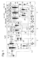
- a first embodiment variant of a hydraulic control device 1.1 according to the invention according to FIG. 1 differs from the known control device 1.0 according to FIG. 7 in that an intermediate valve arrangement 38 is now provided for controlling the volume flow control valve VR-V instead of the pilot control valve 11 designed as an electrical pressure regulator (EDS4) ,
- This intermediate valve arrangement 38 comprises two pressure-controlled pilot valves VV-1, VV-2 designed as slide valves, each having a valve piston, a valve spring, a spring-side control pressure chamber, a spring-side feedback pressure chamber and a central pressure chamber bounded on both sides by control edges of adjacent piston collars of the valve piston.
- the first pilot valve VV-1 is at its control pressure chamber with the working pressure line 18 of the first coupling valve KV-1, at its central pressure chamber on the input side with a connecting line 39 and the output side with an output side control pressure line 40 and at its spring-side feedback pressure chamber with the output side control pressure line 40 in connection.
- the second pilot valve VV-2 is at its control pressure chamber with the working pressure line 19 of the second clutch valve KV-2, at its central pressure chamber on the input side with the control pressure supply line 13 and the output side leading to the first pilot valve VV-1 connecting line 39 and at its spring side Feedback pressure chamber with the output-side control pressure line 40 in conjunction.
- a control pressure for controlling the Volume flow control valve VR-V which is approximately proportional to the average value of the working pressures in the two working pressure lines 18 and 19 of the clutch actuating part 3 behaves.
- the clutch actuating cylinders of the two clutches K1, K2 are advantageously pretensioned via associated return springs, not shown, such that the two clutch valves KV-1, KV-2 each have a lower control range for actuating the pilot valves VV-1, Have VV-2 and an upper control range for controlling the Kupplungsstellzylinder.
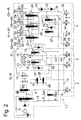
- an intermediate valve arrangement 38 ' is also provided instead of the pilot valve 11 designed as an electrical pressure regulator (EDS4) according to FIG. 7 to control the volume flow control valve VR-V, which largely corresponds to the intermediate valve arrangement 38 according to FIG 1 corresponds.
- EDS4 electrical pressure regulator
- the first pilot valve VV-1 at its control pressure chamber with the control pressure line 16 of the first clutch valve KV-1
- the second pilot valve W-2 at its control pressure chamber with the control pressure line 17 of the second clutch valve KV-2 in combination.
- a control pressure for controlling the volume flow control valve VR-V which is approximately proportional to the average value of the control pressures in the two control pressure lines 16, 17 of the clutch actuation part 3 behaves.
- the two clutch valves KV-1, KV-2 are advantageously biased via associated valve springs such that the pilot valves KV-1, KV-2 upstream pilot valves 14, 15 each have a lower control range for controlling the pilot valves VV-1, VV-2 and an upper control range to control the clutch valves KV-1, KV-2 have.
- FIG. 1 A third embodiment of the hydraulic control device 1.3 according to the invention is shown in FIG. This differs from the known control device 1.0 according to FIG. 7 in that, instead of the pilot control valve 11, an intermediate valve arrangement 41 is provided for controlling the volume flow control valve VR-V, which differs from the intermediate valve arrangements 38 and 38 'of the first two embodiments according to FIGS Fig. 2 recognizable recognizes.
- the present intermediate valve arrangement 41 comprises three shuttle valves KU-V1, KU-V2, KU-V3, each with two inputs and one output.
- the two inputs of the first shuttle valve KU-V1 are each connected to the control pressure line 27, 28 of the first speed valve GV-1 and the second speed valve GV-2
- the two inputs of the second shuttle valve KU-V2 are each with the switching pressure line 33, 35th the two gear selector valve TW-V or the two cylinder selection valves ZW-V1, ZW-V2 in combination
- the two inputs of the third shuttle valve KU-V3 are connected to the outputs of the other two shuttle valves KU-V1 and KU-V2
- the output of the third shuttle valve KU-V3 connected to the output-side control pressure line 40, which leads to the flow control valve VR-V.
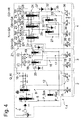
- a fourth embodiment variant of the hydraulic control device 1.4 according to the invention according to FIG. 4 differs from the known control device 1.0 according to FIG. 7 in that, instead of the pilot control valve 11 designed as an electric pressure regulator (EDS4), a solenoid valve valve (FIG. MV3) formed pilot valve 11 'is provided.
- the control pressure set in the control pressure line 12 is set proportionally to a variable clock frequency or, at a fixed clock frequency, proportional to a variable opening rate per clock.
- a second intermediate valve arrangement 42 is provided in addition to the embodiment of FIG. 3 for controlling the main pressure valve HD-V instead of the pilot valve 8 designed as an electrical pressure regulator (EDS3).
- the second intermediate valve arrangement 42 comprises three shuttle valves KU-V4, KU-V5, KU-V6, each with two inputs and one output.
- the two inputs of the first shuttle valve KU-V4 are connected to the working pressure lines 29, 30 of the two speed valves GV-1, GV-2
- the two inputs of the second shuttle valve KU-V5 are connected to the working pressure lines 18, 19 of the two clutch valves KV- 1, KV-2
- the two inputs of the third shuttle valve KU-V6 are in communication with the outputs of the other two shuttle valves KU-V4 and KU-V5.
- At the output of the third shuttle valve KU-V6 leading to a spring-side end pressure chamber of the main pressure valve HD-V output-side control pressure line 43 is connected, which has a diaphragm B and to which a pressure relief valve DB-V1 is connected.
- an intermediate valve arrangement 42 ' is also provided for controlling the main pressure valve HD-V instead of the pilot valve 8 of FIG. 3 designed as an electrical pressure regulator (EDS3), which largely corresponds to the intermediate valve arrangement 42 according to FIG 5 corresponds.
- EDS3 electrical pressure regulator
- the two inputs of the first shuttle valve which in the present case is identical to the first shuttle valve KU-V1 of the intermediate valve assembly 41, with the control pressure lines 27, 28 of the two gear valves GV-1, GV-2 and the two inputs of the second Shuttle valve KU-V5 with the control pressure lines 16, 17 of the two coupling valves KV-1, KV-2 in combination.
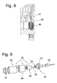
- valve housing 44 is shown by way of example together with a substantially valve piston 45 and an electromagnet 46 comprehensive valve insert 47 of a solenoid valve in Fig. 8.
- the individual parts of a valve insert 47 provided for mounting in a common valve housing 44 are shown in FIG. 9.
- the valve core 47 includes a solenoid 48, a magnet armature 49, a magnet housing 50, an outer pole tube portion 51, an inner pole tube portion 52, an anchor rod 53, two plain bearing bushes 54, and the valve piston 45.
Landscapes
- Engineering & Computer Science (AREA)
- General Engineering & Computer Science (AREA)
- Mechanical Engineering (AREA)
- Physics & Mathematics (AREA)
- Fluid Mechanics (AREA)
- Hydraulic Clutches, Magnetic Clutches, Fluid Clutches, And Fluid Joints (AREA)
- Control Of Transmission Device (AREA)
Applications Claiming Priority (2)
| Application Number | Priority Date | Filing Date | Title |
|---|---|---|---|
| DE102006049973A DE102006049973A1 (de) | 2006-10-24 | 2006-10-24 | Hydraulische Steuerungsvorrichtung eines automatisierten Doppelkupplungsgestriebes |
| DE102006049972A DE102006049972A1 (de) | 2006-10-24 | 2006-10-24 | Hydraulische Steuerungsvorrichtung eines automatisierten Stufenschaltgetriebes |
Publications (3)
| Publication Number | Publication Date |
|---|---|
| EP1916457A2 true EP1916457A2 (fr) | 2008-04-30 |
| EP1916457A3 EP1916457A3 (fr) | 2011-04-20 |
| EP1916457B1 EP1916457B1 (fr) | 2012-08-15 |
Family
ID=38769879
Family Applications (1)
| Application Number | Title | Priority Date | Filing Date |
|---|---|---|---|
| EP07019791A Not-in-force EP1916457B1 (fr) | 2006-10-24 | 2007-10-10 | Dispositif de commande hydraulique d'un engrenage à double embrayage automatisé |
Country Status (2)
| Country | Link |
|---|---|
| EP (1) | EP1916457B1 (fr) |
| DE (1) | DE102006049973A1 (fr) |
Cited By (8)
| Publication number | Priority date | Publication date | Assignee | Title |
|---|---|---|---|---|
| DE102009005754A1 (de) | 2009-01-23 | 2010-07-29 | Daimler Ag | Hydraulische Steuerung für ein automatisiertes Zahnräderwechselgetriebe eines Kraftfahrzeugs |
| DE102009018982A1 (de) | 2009-04-25 | 2010-10-28 | Daimler Ag | Hydraulische Steuerungsvorrichtung für ein Getriebe eines Hybridantriebs |
| EP2292951A1 (fr) * | 2009-09-04 | 2011-03-09 | Honda Motor Co., Ltd. | Système de commande pour transmission |
| CN102378869A (zh) * | 2009-04-01 | 2012-03-14 | Zf腓德烈斯哈芬股份公司 | 液压式变速器控制装置 |
| EP2410213A3 (fr) * | 2010-07-21 | 2012-05-16 | hofer mechatronik GmbH | Système hydraulique de transmission pour boîte de vitesses à plusieurs embrayages et procédé de commande avec des vannes hydrauliques pour des boîtes de vitesses comprenant plusieurs embrayages offrant une meilleure sécurité de fonctionnement |
| WO2014079441A3 (fr) * | 2012-11-26 | 2014-11-20 | Schaeffler Technologies Gmbh & Co. Kg | Commande hydraulique |
| CN107199915A (zh) * | 2017-05-25 | 2017-09-26 | 福建中青汽车技术有限公司 | 一种纯电动车辆换挡系统 |
| DE102018214332A1 (de) * | 2018-08-24 | 2020-02-27 | Zf Friedrichshafen Ag | Hydrauliksystem zum Schalten einer Fahrzeugkupplung |
Families Citing this family (3)
| Publication number | Priority date | Publication date | Assignee | Title |
|---|---|---|---|---|
| DE102015214020B4 (de) * | 2015-07-24 | 2019-07-04 | Zf Friedrichshafen Ag | Hydraulikvorrichtung eines Doppelkupplungsgetriebes |
| CN107588190B (zh) * | 2016-07-08 | 2023-05-16 | 广州汽车集团股份有限公司 | 双离合器自动变速器的液压换挡控制系统 |
| DE102018214435A1 (de) * | 2018-08-27 | 2020-02-27 | Zf Friedrichshafen Ag | Hydrauliksystem zur Betätigung einer Mehrzahl von doppeltwirkenden Aktuatoren eines Getriebes |
Citations (4)
| Publication number | Priority date | Publication date | Assignee | Title |
|---|---|---|---|---|
| DE19727358A1 (de) * | 1996-07-02 | 1998-01-08 | Luk Getriebe Systeme Gmbh | Druckmittelanlage sowie ein Verfahren zu deren Verwendung |
| EP1150040A2 (fr) * | 2000-04-25 | 2001-10-31 | GETRAG Getriebe- und Zahnradfabrik Hermann Hagenmeyer GmbH & Cie | Circuit hydraulique pour une boíte de vitesses à embrayage double automatisée d'un véhicule automobile |
| DE10347203A1 (de) * | 2002-11-18 | 2004-06-03 | Zf Sachs Ag | Kraftfahrzeug-Antriebsstrang mit einer Pumpenanordnung zur Versorgung einer Kupplungseinrichtung mit Druckmedium oder/und Betriebsmedium oder/und zur Versorgung eines Getriebes mit Druckmedium, entsprechende Pumpenanordnung und entsprechende Betätigungsanordnung für die Getriebebetätigung |
| EP1593881A1 (fr) * | 2004-04-22 | 2005-11-09 | BorgWarner Inc. | Dispositif d'alimentation en liquide de refroidissement pour une transmission à double embrayages et procédé d'alimentation en fluide de refroidissement d'une telle transmission |
-
2006
- 2006-10-24 DE DE102006049973A patent/DE102006049973A1/de not_active Withdrawn
-
2007
- 2007-10-10 EP EP07019791A patent/EP1916457B1/fr not_active Not-in-force
Patent Citations (4)
| Publication number | Priority date | Publication date | Assignee | Title |
|---|---|---|---|---|
| DE19727358A1 (de) * | 1996-07-02 | 1998-01-08 | Luk Getriebe Systeme Gmbh | Druckmittelanlage sowie ein Verfahren zu deren Verwendung |
| EP1150040A2 (fr) * | 2000-04-25 | 2001-10-31 | GETRAG Getriebe- und Zahnradfabrik Hermann Hagenmeyer GmbH & Cie | Circuit hydraulique pour une boíte de vitesses à embrayage double automatisée d'un véhicule automobile |
| DE10347203A1 (de) * | 2002-11-18 | 2004-06-03 | Zf Sachs Ag | Kraftfahrzeug-Antriebsstrang mit einer Pumpenanordnung zur Versorgung einer Kupplungseinrichtung mit Druckmedium oder/und Betriebsmedium oder/und zur Versorgung eines Getriebes mit Druckmedium, entsprechende Pumpenanordnung und entsprechende Betätigungsanordnung für die Getriebebetätigung |
| EP1593881A1 (fr) * | 2004-04-22 | 2005-11-09 | BorgWarner Inc. | Dispositif d'alimentation en liquide de refroidissement pour une transmission à double embrayages et procédé d'alimentation en fluide de refroidissement d'une telle transmission |
Cited By (15)
| Publication number | Priority date | Publication date | Assignee | Title |
|---|---|---|---|---|
| DE102009005754B4 (de) * | 2009-01-23 | 2021-04-15 | Daimler Ag | Hydraulische Steuerung für ein automatisiertes Zahnräderwechselgetriebe eines Kraftfahrzeugs |
| DE102009005754A1 (de) | 2009-01-23 | 2010-07-29 | Daimler Ag | Hydraulische Steuerung für ein automatisiertes Zahnräderwechselgetriebe eines Kraftfahrzeugs |
| CN102378869B (zh) * | 2009-04-01 | 2014-12-10 | Zf腓德烈斯哈芬股份公司 | 液压式变速器控制装置 |
| CN102378869A (zh) * | 2009-04-01 | 2012-03-14 | Zf腓德烈斯哈芬股份公司 | 液压式变速器控制装置 |
| DE102009018982A1 (de) | 2009-04-25 | 2010-10-28 | Daimler Ag | Hydraulische Steuerungsvorrichtung für ein Getriebe eines Hybridantriebs |
| CN102011861A (zh) * | 2009-09-04 | 2011-04-13 | 本田技研工业株式会社 | 变速器的控制装置 |
| US8359940B2 (en) | 2009-09-04 | 2013-01-29 | Honda Motor Co., Ltd. | Control system for transmission |
| CN102011861B (zh) * | 2009-09-04 | 2013-08-28 | 本田技研工业株式会社 | 变速器的控制装置 |
| EP2292951A1 (fr) * | 2009-09-04 | 2011-03-09 | Honda Motor Co., Ltd. | Système de commande pour transmission |
| EP2410213A3 (fr) * | 2010-07-21 | 2012-05-16 | hofer mechatronik GmbH | Système hydraulique de transmission pour boîte de vitesses à plusieurs embrayages et procédé de commande avec des vannes hydrauliques pour des boîtes de vitesses comprenant plusieurs embrayages offrant une meilleure sécurité de fonctionnement |
| EP3043089A1 (fr) | 2010-07-21 | 2016-07-13 | hofer mechatronik GmbH | Preparation de fluide hydraulique d'un systeme hydraulique de transmission et procede de fonctionnement du systeme hydraulique de transmission |
| WO2014079441A3 (fr) * | 2012-11-26 | 2014-11-20 | Schaeffler Technologies Gmbh & Co. Kg | Commande hydraulique |
| CN107199915A (zh) * | 2017-05-25 | 2017-09-26 | 福建中青汽车技术有限公司 | 一种纯电动车辆换挡系统 |
| CN107199915B (zh) * | 2017-05-25 | 2023-05-02 | 福建中青汽车技术有限公司 | 一种纯电动车辆换挡系统 |
| DE102018214332A1 (de) * | 2018-08-24 | 2020-02-27 | Zf Friedrichshafen Ag | Hydrauliksystem zum Schalten einer Fahrzeugkupplung |
Also Published As
| Publication number | Publication date |
|---|---|
| EP1916457B1 (fr) | 2012-08-15 |
| DE102006049973A1 (de) | 2008-04-30 |
| EP1916457A3 (fr) | 2011-04-20 |
Similar Documents
| Publication | Publication Date | Title |
|---|---|---|
| EP1916457B1 (fr) | Dispositif de commande hydraulique d'un engrenage à double embrayage automatisé | |
| EP2094996B1 (fr) | Dispositif de commande hydraulique d'une boîte de vitesses automatisée à rapport étagés | |
| EP2382402B1 (fr) | Contrôle hydraulique pour une transmission automatique | |
| DE102006016397B4 (de) | Getriebe und ein Verfahren zur Steuerung eines Getriebes für ein Kraftfahrzeug | |
| EP1150040B1 (fr) | Circuit hydraulique pour une boîte de vitesses à embrayage double automatisée d'un véhicule automobile | |
| EP2382404B1 (fr) | Dispositif de controle pour une transmission automatique avec changement par engrenages | |
| EP1420186B1 (fr) | Transmission pour véhicule automobile comprenant une pompe d'alimentation d'un système d'embrayage en fluide sous pression | |
| WO2011015182A1 (fr) | Système hydraulique de commande hydraulique d'une boîte de vitesses à double embrayage | |
| EP2382403B1 (fr) | Dispositif de contrôle pour une transmission automatique avec changement par engrenages | |
| EP3049687A2 (fr) | Commande hydraulique destinée à une boîte de vitesses à double embrayage de véhicule utilitaire | |
| EP1517059A1 (fr) | Engrenage à double embrayage avec fonction de maintien de position | |
| DE102011100862B4 (de) | Doppelkupplungsgetriebe | |
| WO2012152395A1 (fr) | Boîte de vitesses à embrayage, en particulier boîte de vitesses à double embrayage, dotée d'un accumulateur de pression | |
| DE102013001928A1 (de) | Kraftfahrzeuggetriebevorrichtung mit einem Hydrauliksystem | |
| DE102006003517A1 (de) | Hydraulische Steuereinrichtung und Verfahren zur Ansteuerung zweier Aktuatoren | |
| DE102011100809A1 (de) | Kupplungsgetriebe mit Sicherheitsventilanordnung | |
| DE102009005754B4 (de) | Hydraulische Steuerung für ein automatisiertes Zahnräderwechselgetriebe eines Kraftfahrzeugs | |
| EP2767738B1 (fr) | Agencement de commande hydraulique, engrenage doté de celui-ci et procédé de pré-remplissage | |
| DE102009005752A1 (de) | Steuerungseinrichtung für ein automatisiertes Zahnräderwechselgetriebe eines Kraftfahrzeugs | |
| DE102010025243B4 (de) | Kraftwagen mit einer Lamellenkupplung | |
| DE102011100810B4 (de) | Doppelkupplungsgetriebe, Verfahren zum Betreiben | |
| WO2020043404A1 (fr) | Système hydraulique pour une boîte de vitesses d'un groupe motopropulseur de véhicule automobile | |
| DE102006063034B3 (de) | Verfahren zur Steuerung eines Getriebes für ein Kraftfahrzeug | |
| DE102010013182A1 (de) | Kraftfahrzeuggetriebevorrichtung | |
| DE102009005750A1 (de) | Verfahren zum Betrieb eines Kupplungssteuersystems für ein automatisiertes Getriebe eines Kraftfahrzeugs |
Legal Events
| Date | Code | Title | Description |
|---|---|---|---|
| PUAI | Public reference made under article 153(3) epc to a published international application that has entered the european phase |
Free format text: ORIGINAL CODE: 0009012 |
|
| AK | Designated contracting states |
Kind code of ref document: A2 Designated state(s): AT BE BG CH CY CZ DE DK EE ES FI FR GB GR HU IE IS IT LI LT LU LV MC MT NL PL PT RO SE SI SK TR |
|
| AX | Request for extension of the european patent |
Extension state: AL BA HR MK RS |
|
| PUAL | Search report despatched |
Free format text: ORIGINAL CODE: 0009013 |
|
| AK | Designated contracting states |
Kind code of ref document: A3 Designated state(s): AT BE BG CH CY CZ DE DK EE ES FI FR GB GR HU IE IS IT LI LT LU LV MC MT NL PL PT RO SE SI SK TR |
|
| AX | Request for extension of the european patent |
Extension state: AL BA HR MK RS |
|
| 17P | Request for examination filed |
Effective date: 20111014 |
|
| AKX | Designation fees paid |
Designated state(s): AT BE BG CH CY CZ DE DK EE ES FI FR GB GR HU IE IS IT LI LT LU LV MC MT NL PL PT RO SE SI SK TR |
|
| REG | Reference to a national code |
Ref country code: DE Ref legal event code: R079 Ref document number: 502007010376 Country of ref document: DE Free format text: PREVIOUS MAIN CLASS: F16H0061688000 Ipc: F16H0061280000 |
|
| GRAP | Despatch of communication of intention to grant a patent |
Free format text: ORIGINAL CODE: EPIDOSNIGR1 |
|
| GRAC | Information related to communication of intention to grant a patent modified |
Free format text: ORIGINAL CODE: EPIDOSCIGR1 |
|
| RIC1 | Information provided on ipc code assigned before grant |
Ipc: F16H 61/688 20060101ALI20120227BHEP Ipc: F16H 61/28 20060101AFI20120227BHEP Ipc: F16D 48/02 20060101ALI20120227BHEP Ipc: F16D 25/12 20060101ALI20120227BHEP |
|
| GRAS | Grant fee paid |
Free format text: ORIGINAL CODE: EPIDOSNIGR3 |
|
| GRAA | (expected) grant |
Free format text: ORIGINAL CODE: 0009210 |
|
| AK | Designated contracting states |
Kind code of ref document: B1 Designated state(s): AT BE BG CH CY CZ DE DK EE ES FI FR GB GR HU IE IS IT LI LT LU LV MC MT NL PL PT RO SE SI SK TR |
|
| REG | Reference to a national code |
Ref country code: AT Ref legal event code: REF Ref document number: 571027 Country of ref document: AT Kind code of ref document: T Effective date: 20120815 Ref country code: CH Ref legal event code: EP Ref country code: GB Ref legal event code: FG4D Free format text: NOT ENGLISH |
|
| REG | Reference to a national code |
Ref country code: IE Ref legal event code: FG4D Free format text: LANGUAGE OF EP DOCUMENT: GERMAN |
|
| REG | Reference to a national code |
Ref country code: DE Ref legal event code: R096 Ref document number: 502007010376 Country of ref document: DE Effective date: 20121018 |
|
| REG | Reference to a national code |
Ref country code: NL Ref legal event code: VDEP Effective date: 20120815 |
|
| PG25 | Lapsed in a contracting state [announced via postgrant information from national office to epo] |
Ref country code: IS Free format text: LAPSE BECAUSE OF FAILURE TO SUBMIT A TRANSLATION OF THE DESCRIPTION OR TO PAY THE FEE WITHIN THE PRESCRIBED TIME-LIMIT Effective date: 20121215 Ref country code: FI Free format text: LAPSE BECAUSE OF FAILURE TO SUBMIT A TRANSLATION OF THE DESCRIPTION OR TO PAY THE FEE WITHIN THE PRESCRIBED TIME-LIMIT Effective date: 20120815 Ref country code: LT Free format text: LAPSE BECAUSE OF FAILURE TO SUBMIT A TRANSLATION OF THE DESCRIPTION OR TO PAY THE FEE WITHIN THE PRESCRIBED TIME-LIMIT Effective date: 20120815 Ref country code: CY Free format text: LAPSE BECAUSE OF FAILURE TO SUBMIT A TRANSLATION OF THE DESCRIPTION OR TO PAY THE FEE WITHIN THE PRESCRIBED TIME-LIMIT Effective date: 20120815 |
|
| PG25 | Lapsed in a contracting state [announced via postgrant information from national office to epo] |
Ref country code: GR Free format text: LAPSE BECAUSE OF FAILURE TO SUBMIT A TRANSLATION OF THE DESCRIPTION OR TO PAY THE FEE WITHIN THE PRESCRIBED TIME-LIMIT Effective date: 20121116 Ref country code: PL Free format text: LAPSE BECAUSE OF FAILURE TO SUBMIT A TRANSLATION OF THE DESCRIPTION OR TO PAY THE FEE WITHIN THE PRESCRIBED TIME-LIMIT Effective date: 20120815 Ref country code: SI Free format text: LAPSE BECAUSE OF FAILURE TO SUBMIT A TRANSLATION OF THE DESCRIPTION OR TO PAY THE FEE WITHIN THE PRESCRIBED TIME-LIMIT Effective date: 20120815 Ref country code: PT Free format text: LAPSE BECAUSE OF FAILURE TO SUBMIT A TRANSLATION OF THE DESCRIPTION OR TO PAY THE FEE WITHIN THE PRESCRIBED TIME-LIMIT Effective date: 20121217 Ref country code: LV Free format text: LAPSE BECAUSE OF FAILURE TO SUBMIT A TRANSLATION OF THE DESCRIPTION OR TO PAY THE FEE WITHIN THE PRESCRIBED TIME-LIMIT Effective date: 20120815 Ref country code: SE Free format text: LAPSE BECAUSE OF FAILURE TO SUBMIT A TRANSLATION OF THE DESCRIPTION OR TO PAY THE FEE WITHIN THE PRESCRIBED TIME-LIMIT Effective date: 20120815 |
|
| PG25 | Lapsed in a contracting state [announced via postgrant information from national office to epo] |
Ref country code: NL Free format text: LAPSE BECAUSE OF FAILURE TO SUBMIT A TRANSLATION OF THE DESCRIPTION OR TO PAY THE FEE WITHIN THE PRESCRIBED TIME-LIMIT Effective date: 20120815 |
|
| BERE | Be: lapsed |
Owner name: ZF FRIEDRICHSHAFEN A.G. Effective date: 20121031 |
|
| PG25 | Lapsed in a contracting state [announced via postgrant information from national office to epo] |
Ref country code: ES Free format text: LAPSE BECAUSE OF FAILURE TO SUBMIT A TRANSLATION OF THE DESCRIPTION OR TO PAY THE FEE WITHIN THE PRESCRIBED TIME-LIMIT Effective date: 20121126 Ref country code: RO Free format text: LAPSE BECAUSE OF FAILURE TO SUBMIT A TRANSLATION OF THE DESCRIPTION OR TO PAY THE FEE WITHIN THE PRESCRIBED TIME-LIMIT Effective date: 20120815 Ref country code: CZ Free format text: LAPSE BECAUSE OF FAILURE TO SUBMIT A TRANSLATION OF THE DESCRIPTION OR TO PAY THE FEE WITHIN THE PRESCRIBED TIME-LIMIT Effective date: 20120815 Ref country code: DK Free format text: LAPSE BECAUSE OF FAILURE TO SUBMIT A TRANSLATION OF THE DESCRIPTION OR TO PAY THE FEE WITHIN THE PRESCRIBED TIME-LIMIT Effective date: 20120815 Ref country code: EE Free format text: LAPSE BECAUSE OF FAILURE TO SUBMIT A TRANSLATION OF THE DESCRIPTION OR TO PAY THE FEE WITHIN THE PRESCRIBED TIME-LIMIT Effective date: 20120815 |
|
| PG25 | Lapsed in a contracting state [announced via postgrant information from national office to epo] |
Ref country code: MC Free format text: LAPSE BECAUSE OF NON-PAYMENT OF DUE FEES Effective date: 20121031 Ref country code: SK Free format text: LAPSE BECAUSE OF FAILURE TO SUBMIT A TRANSLATION OF THE DESCRIPTION OR TO PAY THE FEE WITHIN THE PRESCRIBED TIME-LIMIT Effective date: 20120815 Ref country code: IT Free format text: LAPSE BECAUSE OF FAILURE TO SUBMIT A TRANSLATION OF THE DESCRIPTION OR TO PAY THE FEE WITHIN THE PRESCRIBED TIME-LIMIT Effective date: 20120815 |
|
| REG | Reference to a national code |
Ref country code: CH Ref legal event code: PL |
|
| PLBE | No opposition filed within time limit |
Free format text: ORIGINAL CODE: 0009261 |
|
| STAA | Information on the status of an ep patent application or granted ep patent |
Free format text: STATUS: NO OPPOSITION FILED WITHIN TIME LIMIT |
|
| REG | Reference to a national code |
Ref country code: IE Ref legal event code: MM4A |
|
| 26N | No opposition filed |
Effective date: 20130516 |
|
| GBPC | Gb: european patent ceased through non-payment of renewal fee |
Effective date: 20121115 |
|
| REG | Reference to a national code |
Ref country code: FR Ref legal event code: ST Effective date: 20130628 |
|
| PG25 | Lapsed in a contracting state [announced via postgrant information from national office to epo] |
Ref country code: IE Free format text: LAPSE BECAUSE OF NON-PAYMENT OF DUE FEES Effective date: 20121010 Ref country code: CH Free format text: LAPSE BECAUSE OF NON-PAYMENT OF DUE FEES Effective date: 20121031 Ref country code: LI Free format text: LAPSE BECAUSE OF NON-PAYMENT OF DUE FEES Effective date: 20121031 Ref country code: BG Free format text: LAPSE BECAUSE OF FAILURE TO SUBMIT A TRANSLATION OF THE DESCRIPTION OR TO PAY THE FEE WITHIN THE PRESCRIBED TIME-LIMIT Effective date: 20121115 Ref country code: BE Free format text: LAPSE BECAUSE OF NON-PAYMENT OF DUE FEES Effective date: 20121031 |
|
| PG25 | Lapsed in a contracting state [announced via postgrant information from national office to epo] |
Ref country code: FR Free format text: LAPSE BECAUSE OF NON-PAYMENT OF DUE FEES Effective date: 20121031 |
|
| REG | Reference to a national code |
Ref country code: DE Ref legal event code: R097 Ref document number: 502007010376 Country of ref document: DE Effective date: 20130516 |
|
| PG25 | Lapsed in a contracting state [announced via postgrant information from national office to epo] |
Ref country code: MT Free format text: LAPSE BECAUSE OF FAILURE TO SUBMIT A TRANSLATION OF THE DESCRIPTION OR TO PAY THE FEE WITHIN THE PRESCRIBED TIME-LIMIT Effective date: 20120815 Ref country code: GB Free format text: LAPSE BECAUSE OF NON-PAYMENT OF DUE FEES Effective date: 20121115 |
|
| REG | Reference to a national code |
Ref country code: AT Ref legal event code: MM01 Ref document number: 571027 Country of ref document: AT Kind code of ref document: T Effective date: 20121031 |
|
| PG25 | Lapsed in a contracting state [announced via postgrant information from national office to epo] |
Ref country code: AT Free format text: LAPSE BECAUSE OF NON-PAYMENT OF DUE FEES Effective date: 20121031 |
|
| PGFP | Annual fee paid to national office [announced via postgrant information from national office to epo] |
Ref country code: DE Payment date: 20131002 Year of fee payment: 7 |
|
| PG25 | Lapsed in a contracting state [announced via postgrant information from national office to epo] |
Ref country code: TR Free format text: LAPSE BECAUSE OF FAILURE TO SUBMIT A TRANSLATION OF THE DESCRIPTION OR TO PAY THE FEE WITHIN THE PRESCRIBED TIME-LIMIT Effective date: 20120815 |
|
| PG25 | Lapsed in a contracting state [announced via postgrant information from national office to epo] |
Ref country code: LU Free format text: LAPSE BECAUSE OF NON-PAYMENT OF DUE FEES Effective date: 20121010 |
|
| PG25 | Lapsed in a contracting state [announced via postgrant information from national office to epo] |
Ref country code: HU Free format text: LAPSE BECAUSE OF FAILURE TO SUBMIT A TRANSLATION OF THE DESCRIPTION OR TO PAY THE FEE WITHIN THE PRESCRIBED TIME-LIMIT Effective date: 20071010 |
|
| REG | Reference to a national code |
Ref country code: DE Ref legal event code: R119 Ref document number: 502007010376 Country of ref document: DE |
|
| PG25 | Lapsed in a contracting state [announced via postgrant information from national office to epo] |
Ref country code: DE Free format text: LAPSE BECAUSE OF NON-PAYMENT OF DUE FEES Effective date: 20150501 |