EP1916197A1 - Blade handling tray insert - Google Patents
Blade handling tray insert Download PDFInfo
- Publication number
- EP1916197A1 EP1916197A1 EP07254209A EP07254209A EP1916197A1 EP 1916197 A1 EP1916197 A1 EP 1916197A1 EP 07254209 A EP07254209 A EP 07254209A EP 07254209 A EP07254209 A EP 07254209A EP 1916197 A1 EP1916197 A1 EP 1916197A1
- Authority
- EP
- European Patent Office
- Prior art keywords
- tray
- tray insert
- handling
- gas turbine
- turbine engine
- Prior art date
- Legal status (The legal status is an assumption and is not a legal conclusion. Google has not performed a legal analysis and makes no representation as to the accuracy of the status listed.)
- Withdrawn
Links
- 239000012530 fluid Substances 0.000 claims abstract description 23
- 238000000034 method Methods 0.000 claims description 7
- 238000003780 insertion Methods 0.000 claims description 6
- 230000037431 insertion Effects 0.000 claims description 6
- 239000000463 material Substances 0.000 claims description 4
- 239000007789 gas Substances 0.000 description 27
- 239000004698 Polyethylene Substances 0.000 description 1
- 239000000446 fuel Substances 0.000 description 1
- 238000001746 injection moulding Methods 0.000 description 1
- 238000004519 manufacturing process Methods 0.000 description 1
- 239000004033 plastic Substances 0.000 description 1
- 229920003023 plastic Polymers 0.000 description 1
- -1 polyethylene Polymers 0.000 description 1
- 229920000573 polyethylene Polymers 0.000 description 1
Images


Classifications
-
- B—PERFORMING OPERATIONS; TRANSPORTING
- B65—CONVEYING; PACKING; STORING; HANDLING THIN OR FILAMENTARY MATERIAL
- B65D—CONTAINERS FOR STORAGE OR TRANSPORT OF ARTICLES OR MATERIALS, e.g. BAGS, BARRELS, BOTTLES, BOXES, CANS, CARTONS, CRATES, DRUMS, JARS, TANKS, HOPPERS, FORWARDING CONTAINERS; ACCESSORIES, CLOSURES, OR FITTINGS THEREFOR; PACKAGING ELEMENTS; PACKAGES
- B65D25/00—Details of other kinds or types of rigid or semi-rigid containers
- B65D25/02—Internal fittings
- B65D25/10—Devices to locate articles in containers
-
- B—PERFORMING OPERATIONS; TRANSPORTING
- B65—CONVEYING; PACKING; STORING; HANDLING THIN OR FILAMENTARY MATERIAL
- B65D—CONTAINERS FOR STORAGE OR TRANSPORT OF ARTICLES OR MATERIALS, e.g. BAGS, BARRELS, BOTTLES, BOXES, CANS, CARTONS, CRATES, DRUMS, JARS, TANKS, HOPPERS, FORWARDING CONTAINERS; ACCESSORIES, CLOSURES, OR FITTINGS THEREFOR; PACKAGING ELEMENTS; PACKAGES
- B65D25/00—Details of other kinds or types of rigid or semi-rigid containers
- B65D25/02—Internal fittings
- B65D25/10—Devices to locate articles in containers
- B65D25/107—Grooves, ribs, or the like, situated on opposed walls and between which the articles are located
-
- B—PERFORMING OPERATIONS; TRANSPORTING
- B65—CONVEYING; PACKING; STORING; HANDLING THIN OR FILAMENTARY MATERIAL
- B65D—CONTAINERS FOR STORAGE OR TRANSPORT OF ARTICLES OR MATERIALS, e.g. BAGS, BARRELS, BOTTLES, BOXES, CANS, CARTONS, CRATES, DRUMS, JARS, TANKS, HOPPERS, FORWARDING CONTAINERS; ACCESSORIES, CLOSURES, OR FITTINGS THEREFOR; PACKAGING ELEMENTS; PACKAGES
- B65D2585/00—Containers, packaging elements or packages specially adapted for particular articles or materials
- B65D2585/68—Containers, packaging elements or packages specially adapted for particular articles or materials for machines, engines, or vehicles in assembled or dismantled form
- B65D2585/6802—Containers, packaging elements or packages specially adapted for particular articles or materials for machines, engines, or vehicles in assembled or dismantled form specific machines, engines or vehicles
- B65D2585/6875—Containers, packaging elements or packages specially adapted for particular articles or materials for machines, engines, or vehicles in assembled or dismantled form specific machines, engines or vehicles engines, motors, machines and vehicle parts
-
- B—PERFORMING OPERATIONS; TRANSPORTING
- B65—CONVEYING; PACKING; STORING; HANDLING THIN OR FILAMENTARY MATERIAL
- B65D—CONTAINERS FOR STORAGE OR TRANSPORT OF ARTICLES OR MATERIALS, e.g. BAGS, BARRELS, BOTTLES, BOXES, CANS, CARTONS, CRATES, DRUMS, JARS, TANKS, HOPPERS, FORWARDING CONTAINERS; ACCESSORIES, CLOSURES, OR FITTINGS THEREFOR; PACKAGING ELEMENTS; PACKAGES
- B65D81/00—Containers, packaging elements, or packages, for contents presenting particular transport or storage problems, or adapted to be used for non-packaging purposes after removal of contents
- B65D81/02—Containers, packaging elements, or packages, for contents presenting particular transport or storage problems, or adapted to be used for non-packaging purposes after removal of contents specially adapted to protect contents from mechanical damage
- B65D81/05—Containers, packaging elements, or packages, for contents presenting particular transport or storage problems, or adapted to be used for non-packaging purposes after removal of contents specially adapted to protect contents from mechanical damage maintaining contents at spaced relation from package walls, or from other contents
Definitions
- This invention relates generally to a tray insert. More particularly this invention relates to a tray insert for securing gas turbine engine blades in a handling tray.
- Turbine blades include a root portion, which is commonly shaped like a "fir tree,” for engaging with a rotor disk and an airfoil portion for positioning within the gas path of the engine.
- gas turbine engines Due to design complexity, gas turbine engines have high manufacturing costs. Therefore, fluid reaction members, such as blades and vanes, are expensive.
- fluid reaction members such as blades and vanes
- the elongated configuration of the airfoil portion of gas turbine engine blades makes them fragile and susceptible to damage. As a result, when moving or transporting gas turbine engine blades, the handler must be extremely careful.
- the tray insert for securing fluid reaction members in a handling tray.
- the tray insert includes a body having first and second major surfaces and first and second ends, sliding members disposed on the first and second ends, which are configured to engage with a plurality of slots formed in the handling tray and a first plurality of sockets extending into the first major surface, which are spaced from one another to receive and support a plurality of fluid reaction members.
- the tray insert is configured to hold the fluid reaction members in a suspended state, which prevents them from coming into contact with each other or a surface of the handling tray.
- the present invention provides a tray insert for securing fluid reaction members in a handling tray.
- the tray insert is designed to hold the fluid reaction members, in particular gas turbine engine blades, in a suspended state. This prevents the fluid reaction members from being damaged during handling and/or shipping.
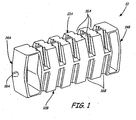
- FIG. 1 is a perspective view of an exemplary embodiment of blade handling tray insert 10.
- Tray insert 10 includes first major surface 12A, second major surface 12B, first end 14A and second end 14B.
- First plurality of sockets 16A extend into first major surface 12A.
- Second plurality of sockets 16B extend into second major surface 12B.
- Sliding member 18A is disposed on first end 14A. (A second sliding member, sliding member 18B, is disposed on second end 14B, but cannot be seen from this perspective.)
- Tray insert 10 is configured to securely hold a plurality of gas turbine engine blades.
- Sockets 16A, 16B are each designed to receive a portion of a blade.
- the spacing of sockets 16A, 16B can vary depending upon the size of the blades (or other types of fluid reaction members) which need to be secured for handling. In the exemplary embodiment shown in FIG. 1, there are ten sockets 16A and ten sockets 16B. However, it should be understood that the number of sockets will vary according to the desired application.
- tray insert 10 includes first major surface 12A, into which sockets 16A extend, and second major surface 12B, into which sockets 16B extend. Sockets 16A are spaced to receive and secure a first type of gas turbine engine blade, such as a first stage blade. Sockets 16B are configured to receive and secure a second type of gas turbine engine blade, such as a second stage blade. Tray insert 10 may be seated in a handling tray such that first major surface 12A is oriented in an upward direction. In contrast, tray insert 10 may also be seated in a handling tray such that second major surface 12B is oriented in an upward direction.
- an appropriate major surface 12A, 12B may be selected depending upon which plurality of sockets 16A, 16B corresponds to the shape and size of the blade to be handled. However, if it is desired that only one type of blade be handled, it should also be understood that plurality of sockets 16A or 16B may extend into only one major surface 12A or 12B of tray insert 10.
- tray insert 10 may be comprised of any suitable material, in particular, tray insert 10 may be comprised of a polymeric material, such as polyethylene. When comprised of a plastic type material, tray insert 10 may be produced by an injection molding process.
- FIG. 2 is a top view of handling tray 20 containing tray insert 10 and demonstrates the blade insertion process.
- Tray insert 10 includes first major surface 12A, second major surface 12B, first end 14A and second end 14B, first plurality of sockets 16A and sliding members 18A, 18B.
- Handling tray 20 includes side portions 22A-22D, bottom portion 24 and receiving slots 26.
- Gas turbine engine blades 28 include root 30, platform 32 and airfoil 34.
- Tray insert 10 may be seated in handling tray 20 by engaging sliding members 18A, 18B with receiving slots 26, which are formed into the inside surface of side portions 22A-22D of handling tray 20. As can be seen in FIG. 2, side portions 22A-22D of handling tray 20 may comprise a number of receiving slots 26. As a result, tray insert 10 may be placed in numerous positions with respect to handling tray 20 in order to accommodate a variety of blade lengths.
- FIG. 2 shows tray insert 10 seated in handling tray 20 such that major surface 12A is oriented in an upward direction, as explained with reference to FIG. 1, tray insert 10 may also be seated in handling tray 20 such that major surface 12B is oriented in an upward direction and plurality of sockets 16B are accessible.
- Root 30 of gas turbine engine blade 26 is designed to have a "fir tree" configuration, which engages with a rotor disk.
- Plurality of sockets 16A are configured to engage with root 30 and therefore, have a corresponding "fir tree” shape. Since root 30 and plurality of sockets 16A have a dovetail relationship, as shown in FIG.
- gas turbine engine blade 26 is inserted into plurality of sockets 16A by matching up the corresponding shapes and lowering blade gas turbine engine blade 26 downward to engage with plurality of sockets 16A like a puzzle piece. Once gas turbine engine blade 26 and plurality of sockets 16A are properly engaged, gas turbine engine blade 26 may only be disengaged through the same angle of insertion.
- FIG. 3 is a top view of handling tray 20 containing tray insert 10 as it secures two gas turbine engine blades 26.
- Tray insert 10 includes first major surface 12A, second major surface 12B, first end 14A and second end 14B, first plurality of sockets 16A and sliding members 18A, 18B.
- Handling tray 20 includes side portions 22A-22D, bottom portion 24 and receiving slots 26.
- Gas turbine engine blades 28 include root 30, platform 32 and airfoil 34.
- gas turbine engine blades 26 are engaged with plurality of sockets 16A by inserting root 30 into a corresponding socket 16A.
- root 30 When root 30 is properly placed within socket 16A, platform 32 of gas turbine engine blade 26 will sit securely against the surface of tray insert 10. Since root 30 fits snuggly within socket 16A, airfoil 34 is held in a suspended state. This prevents airfoil 34 from coming into contact with other gas turbine engine blades 28 and also prevents airfoil 34 from contacting any surface of handling tray 20.
- Process Incidental Damage PID
- PID Process Incidental Damage
Landscapes
- Engineering & Computer Science (AREA)
- Mechanical Engineering (AREA)
- Turbine Rotor Nozzle Sealing (AREA)
Abstract
Description
- This invention relates generally to a tray insert. More particularly this invention relates to a tray insert for securing gas turbine engine blades in a handling tray.
- During operation of a gas turbine engine, fuel is combusted in compressed air created by a compressor to produce heated gases. The heated gases move in a downstream/aft direction past stator vanes and are used to turn turbine blades to produce rotational power for, among other things, operating the compressor. Turbine blades include a root portion, which is commonly shaped like a "fir tree," for engaging with a rotor disk and an airfoil portion for positioning within the gas path of the engine.
- Due to design complexity, gas turbine engines have high manufacturing costs. Therefore, fluid reaction members, such as blades and vanes, are expensive. In addition, the elongated configuration of the airfoil portion of gas turbine engine blades makes them fragile and susceptible to damage. As a result, when moving or transporting gas turbine engine blades, the handler must be extremely careful.
- Known devices and methods for handling gas turbine engine blades are potentially problematic because it is possible for the airfoil portions of the blades to come into contact with each other, causing damage to one or multiple blades. Also, since the airfoil portions of the blades are in contact with surfaces of the receptacle containing the blades, such as a tray, damage to the blades may be incurred when the tray is inappropriately handled. When Process Incidental Damage (PID) occurs, both time and money are lost, as the blades then need to be replaced.
- Therefore, it is desired to provide a blade handling tray insert, which enables gas turbine engine fluid reaction members, especially blades and vanes, to be safely and easily handled, thereby reducing PID.
- From one aspect of the present invention provides a tray insert for securing fluid reaction members in a handling tray. The tray insert includes a body having first and second major surfaces and first and second ends, sliding members disposed on the first and second ends, which are configured to engage with a plurality of slots formed in the handling tray and a first plurality of sockets extending into the first major surface, which are spaced from one another to receive and support a plurality of fluid reaction members. The tray insert is configured to hold the fluid reaction members in a suspended state, which prevents them from coming into contact with each other or a surface of the handling tray.
-
- FIG. 1A is a perspective view of an exemplary embodiment of a blade handling tray insert.
- FIG. 2 is a top view of a handling tray containing the tray insert securing a first blade and receiving a second blade.
- FIG. 3 is a top view of the handling tray containing the tray insert securing two blades.
- In general, the present invention provides a tray insert for securing fluid reaction members in a handling tray. The tray insert is designed to hold the fluid reaction members, in particular gas turbine engine blades, in a suspended state. This prevents the fluid reaction members from being damaged during handling and/or shipping.
- FIG. 1 is a perspective view of an exemplary embodiment of blade
handling tray insert 10. Trayinsert 10 includes firstmajor surface 12A, secondmajor surface 12B,first end 14A andsecond end 14B. First plurality ofsockets 16A extend into firstmajor surface 12A. Second plurality of sockets 16B extend into secondmajor surface 12B. Slidingmember 18A is disposed onfirst end 14A. (A second sliding member, slidingmember 18B, is disposed onsecond end 14B, but cannot be seen from this perspective.) - Tray
insert 10 is configured to securely hold a plurality of gas turbine engine blades.Sockets 16A, 16B are each designed to receive a portion of a blade. The spacing ofsockets 16A, 16B can vary depending upon the size of the blades (or other types of fluid reaction members) which need to be secured for handling. In the exemplary embodiment shown in FIG. 1, there are tensockets 16A and ten sockets 16B. However, it should be understood that the number of sockets will vary according to the desired application. - In addition, in the exemplary embodiment shown in FIG. 1,
tray insert 10 includes firstmajor surface 12A, into whichsockets 16A extend, and secondmajor surface 12B, into which sockets 16B extend.Sockets 16A are spaced to receive and secure a first type of gas turbine engine blade, such as a first stage blade. Sockets 16B are configured to receive and secure a second type of gas turbine engine blade, such as a second stage blade. Trayinsert 10 may be seated in a handling tray such that firstmajor surface 12A is oriented in an upward direction. In contrast,tray insert 10 may also be seated in a handling tray such that secondmajor surface 12B is oriented in an upward direction. As a result, an appropriatemajor surface sockets 16A, 16B corresponds to the shape and size of the blade to be handled. However, if it is desired that only one type of blade be handled, it should also be understood that plurality ofsockets 16A or 16B may extend into only onemajor surface tray insert 10. - While
tray insert 10 may be comprised of any suitable material, in particular,tray insert 10 may be comprised of a polymeric material, such as polyethylene. When comprised of a plastic type material,tray insert 10 may be produced by an injection molding process. - FIG. 2 is a top view of handling
tray 20 containingtray insert 10 and demonstrates the blade insertion process.Tray insert 10 includes firstmajor surface 12A, secondmajor surface 12B,first end 14A andsecond end 14B, first plurality ofsockets 16A and slidingmembers tray 20 includesside portions 22A-22D,bottom portion 24 and receivingslots 26. Gasturbine engine blades 28 includeroot 30,platform 32 and airfoil 34. - Tray
insert 10 may be seated in handlingtray 20 by engaging slidingmembers slots 26, which are formed into the inside surface ofside portions 22A-22D of handlingtray 20. As can be seen in FIG. 2,side portions 22A-22D of handlingtray 20 may comprise a number of receivingslots 26. As a result,tray insert 10 may be placed in numerous positions with respect to handlingtray 20 in order to accommodate a variety of blade lengths. - Once
tray insert 10 is firmly seated within handlingtray 20, gasturbine engine blade 26 may be inserted into plurality ofsockets 16A. (Although FIG. 2shows tray insert 10 seated in handlingtray 20 such thatmajor surface 12A is oriented in an upward direction, as explained with reference to FIG. 1,tray insert 10 may also be seated in handlingtray 20 such thatmajor surface 12B is oriented in an upward direction and plurality of sockets 16B are accessible.)Root 30 of gasturbine engine blade 26 is designed to have a "fir tree" configuration, which engages with a rotor disk. Plurality ofsockets 16A are configured to engage withroot 30 and therefore, have a corresponding "fir tree" shape. Sinceroot 30 and plurality ofsockets 16A have a dovetail relationship, as shown in FIG. 2, gasturbine engine blade 26 is inserted into plurality ofsockets 16A by matching up the corresponding shapes and lowering blade gasturbine engine blade 26 downward to engage with plurality ofsockets 16A like a puzzle piece. Once gasturbine engine blade 26 and plurality ofsockets 16A are properly engaged, gasturbine engine blade 26 may only be disengaged through the same angle of insertion. - FIG. 3 is a top view of handling
tray 20 containingtray insert 10 as it secures two gasturbine engine blades 26.Tray insert 10 includes firstmajor surface 12A, secondmajor surface 12B,first end 14A andsecond end 14B, first plurality ofsockets 16A and slidingmembers tray 20 includesside portions 22A-22D,bottom portion 24 and receivingslots 26. Gasturbine engine blades 28 includeroot 30,platform 32 and airfoil 34. - As described with respect to FIG. 2, gas
turbine engine blades 26 are engaged with plurality ofsockets 16A by insertingroot 30 into acorresponding socket 16A. Whenroot 30 is properly placed withinsocket 16A,platform 32 of gasturbine engine blade 26 will sit securely against the surface oftray insert 10. Sinceroot 30 fits snuggly withinsocket 16A,airfoil 34 is held in a suspended state. This preventsairfoil 34 from coming into contact with other gasturbine engine blades 28 and also preventsairfoil 34 from contacting any surface of handlingtray 20. As a result, when handlingtray 20 is transported, Process Incidental Damage (PID) is unlikely to occur to gasturbine engine blades 28 becauseairfoil 34 protected from potential breakage and awareness to the handler is increased due the highly visible state ofairfoil 34. - Although the present invention has been described with reference to preferred embodiments, workers skilled in the art will recognize that changes may be made in form and detail without departing from the scope of the invention.
Claims (19)
- A tray insert (10) for securing fluid reaction members (28) in a handling tray (20), the tray insert (10) comprising:a body having first and second major surfaces (12A, 12B) and first and second ends (14A, 14B);sliding members (18A, 18B) disposed on the first and second ends (14A, 14B), the sliding members (18A, 18B) being configured to engage with a plurality of slots (26) formed in the handling tray (20); anda first plurality of sockets (16A) extending into the first major surface (12A) and being spaced from one another to receive and support a first plurality of fluid reaction members (28), wherein the tray insert (10) is configured to hold the first plurality of fluid reaction members (28) in a suspended state, which prevents the fluid reaction members (28) from coming into contact with each other or a surface of the handling tray (20).
- The tray insert of claim 1, comprising a second plurality of sockets (16B) extending into the second major surface (12B) and being spaced from one another to receive and support a second plurality of fluid reaction members (28).
- The tray insert of claim 2, wherein the tray insert (10) is insertable into the handling tray (20) such that the first major surface (12A) is positioned in an upward orientation allowing the first plurality of sockets (16A) to be utilized.
- The tray insert of claim 2 or 3, wherein the tray insert (10) is insertable into the handling tray such that the second major surface (12B) is positioned in an upward orientation allowing the second plurality of slots (12B) to be utilized.
- The tray insert of claim 2, 3 or 4 wherein the first plurality of sockets (16A) are configured to receive a plurality of fluid reaction members (28) having a first configuration and the second plurality of sockets (16B) are configured to receive a plurality of fluid reaction members (28) having a second configuration which is different than the first configuration.
- The tray insert of any of claims 2 to 5, wherein the first and second pluralities of sockets (16A, 16B) each comprises ten sockets.
- The tray insert of any of claims 2 to 6, wherein the first and second pluralities of sockets (16A, 16B) are further configured to receive the plurality of fluid reaction members (28) from a defined angle of insertion.
- The tray insert of claim 7 wherein the plurality of fluid reaction members (28) may only be disengaged from the first and second pluralities of sockets (16A,16B) from the defined angle of insertion.
- The tray insert of any preceding claim, wherein the tray insert (10) is further configured to hold the plurality of fluid reaction members (28) in a suspended state in which the fluid reaction members are suspended in an orientation parallel to a bottom surface of the handling tray (20).
- A tray insert (10) for securely handling gas turbine engine blades (28), the tray insert (10) comprising:a body comprising first and second receiving surfaces (12A, 12B) and first and second ends (14A, 14B) wherein the first and second receiving surfaces (12A, 12B) each comprise a plurality of cavities (16A, 16B) each configured to mate with and being spaced to support a root portion (30) of a gas turbine engine blade (28);sliding connectors (18A, 18B) located on the first and second ends (14A, 14B) configured for sliding engagement with a plurality of slots (26) formed in a handling tray (20); andwherein the tray insert (10) is configured to hold a plurality of gas turbine engine blades (28) in an orientation which prevents an airfoil portion of each gas turbine engine blade (28) from coming into contact with any surface.
- The tray insert of claim 10, wherein the tray insert (10) may be seated in the handling tray (20) such that the first receiving surface (12A) is positioned in an upward orientation which allows the first plurality of cavities (16A) to each receive a root portion (30) of a gas turbine engine blade (28).
- The tray insert of claim 10 or 11, wherein the tray insert (10) may be seated in the handling tray (20) such that the second receiving surface (12B) is positioned in an upward orientation which allows the second plurality of cavities (16B) to each receive a root portion (30) of a gas turbine engine blade (28).
- The tray insert of claim 10, 11 or 12, wherein the first plurality of cavities (16A) are configured to each receive a root portion (30) having a first shape and the second plurality of cavities (16B) are configured to each receive a root portion (20) having a second shape which is different than the first shape.
- The tray insert of any of claim 10 to 13, wherein the tray insert (10) is further configured to hold the root portions (30) so that the airfoil portions are suspended in an orientation parallel to a bottom surface of the handling tray (20).
- The tray insert of any of claims 10 to 14, wherein the first and second pluralities of cavities (16A, 16B) are further configured to receive the plurality of gas turbine engine blades (28) from a defined angle of insertion.
- The tray insert of claim 15 wherein the plurality of gas turbine engine blades (28) may only be disengaged from the first and second plurality of cavities (16A, 16B) from the defined angle of insertion.
- The tray insert of any preceding claim, wherein the tray insert (10) is composed of a polymeric material.
- A method for securing and handling gas turbine engine blades (28) in a tray insert (10) of a handling tray (20), the method comprising:seating the tray insert (10) in the handling tray (20) by inserting sliding members (18A, 18B) disposed on first and second end (14A, 14B) of the tray insert (10) into a plurality of slots (26) formed in the handling tray (20) so that a first receiving surface (12A) is positioned in an upward orientation; andinserting root portions (30) of a plurality of gas turbine engine blades (28) into a plurality of cavities (16A) extending into the first receiving surface (12A) which each have a configuration corresponding to the specific configuration of the root portions (30) and are spaced from each other such that airfoil portions of the gas turbine engine blades (28) are suspended in an orientation which prevents them from coming into contact with each other or any surface of the handling tray.
- The method of claim 19 wherein root portions (30) of a plurality of gas turbine engine blades (28) may be inserted into a plurality of cavities (16B) extending into a second receiving surface (12B) depending on the specific configuration of the root portions (30) of the plurality of gas turbine engine blades (28) to be secured.
Applications Claiming Priority (1)
| Application Number | Priority Date | Filing Date | Title |
|---|---|---|---|
| US11/586,157 US20080099358A1 (en) | 2006-10-25 | 2006-10-25 | Blade handling tray insert |
Publications (1)
| Publication Number | Publication Date |
|---|---|
| EP1916197A1 true EP1916197A1 (en) | 2008-04-30 |
Family
ID=39009652
Family Applications (1)
| Application Number | Title | Priority Date | Filing Date |
|---|---|---|---|
| EP07254209A Withdrawn EP1916197A1 (en) | 2006-10-25 | 2007-10-24 | Blade handling tray insert |
Country Status (2)
| Country | Link |
|---|---|
| US (1) | US20080099358A1 (en) |
| EP (1) | EP1916197A1 (en) |
Cited By (3)
| Publication number | Priority date | Publication date | Assignee | Title |
|---|---|---|---|---|
| CN103465103A (en) * | 2013-08-24 | 2013-12-25 | 桐乡市易锋机械厂 | Pxe piston turnover box |
| KR101407817B1 (en) * | 2009-12-03 | 2014-06-17 | 지멘스 악티엔게젤샤프트 | Flexible shipment packaging |
| CN109353649A (en) * | 2018-11-20 | 2019-02-19 | 中国航发贵州黎阳航空动力有限公司 | A kind of turnover box for engine blade processing turnover |
Families Citing this family (8)
| Publication number | Priority date | Publication date | Assignee | Title |
|---|---|---|---|---|
| JP6116193B2 (en) * | 2012-11-08 | 2017-04-19 | 三菱重工業株式会社 | Wing body packing method and wing body packing set |
| US10343702B2 (en) * | 2015-01-05 | 2019-07-09 | Deflecto, LLC | Technologies for caddy assemblies |
| CN105752456B (en) * | 2016-03-25 | 2018-06-05 | 京东方科技集团股份有限公司 | Packing case and packing method |
| US10689187B2 (en) * | 2016-11-28 | 2020-06-23 | Mitsubishi Heavy Industries Compressor Corporation | Rotor securing jig and rotor storage unit |
| DE102020127889A1 (en) * | 2020-10-22 | 2022-04-28 | Feurer Febra Gmbh | charge carrier |
| KR20220087605A (en) * | 2020-12-17 | 2022-06-27 | 삼성디스플레이 주식회사 | Tray |
| US11472020B2 (en) | 2021-01-15 | 2022-10-18 | Stanley Black & Decker, Inc. | Utility knife blade holder for tool container system |
| KR20230118203A (en) * | 2022-02-03 | 2023-08-11 | 삼성디스플레이 주식회사 | Tray |
Citations (5)
| Publication number | Priority date | Publication date | Assignee | Title |
|---|---|---|---|---|
| US5423422A (en) * | 1994-03-14 | 1995-06-13 | Empak, Inc. | Flat panel display container |
| US5628403A (en) | 1996-01-16 | 1997-05-13 | Bill Thomas Associates, Inc. | Universal turbine blade packaging container |
| WO2000009421A1 (en) * | 1998-08-14 | 2000-02-24 | Black & Decker Inc. | Tool container |
| DE10214161C1 (en) * | 2002-03-28 | 2003-05-28 | Willibald Hergeth | Package for transporting turbine blades of different sizes has frusto-conical sections with surfaces which support blade laid diagonally across section |
| EP1645525A1 (en) * | 2004-10-05 | 2006-04-12 | Siemens Aktiengesellschaft | Container for fragile items |
Family Cites Families (2)
| Publication number | Priority date | Publication date | Assignee | Title |
|---|---|---|---|---|
| JPH09150878A (en) * | 1995-11-27 | 1997-06-10 | Hamano Shizuko | Holder for packaging decoration electric lamp assembly |
| US8308015B2 (en) * | 2005-05-05 | 2012-11-13 | Bradford Company | Collapsible container having sliding support member assemblies for supporting dunnage |
-
2006
- 2006-10-25 US US11/586,157 patent/US20080099358A1/en not_active Abandoned
-
2007
- 2007-10-24 EP EP07254209A patent/EP1916197A1/en not_active Withdrawn
Patent Citations (5)
| Publication number | Priority date | Publication date | Assignee | Title |
|---|---|---|---|---|
| US5423422A (en) * | 1994-03-14 | 1995-06-13 | Empak, Inc. | Flat panel display container |
| US5628403A (en) | 1996-01-16 | 1997-05-13 | Bill Thomas Associates, Inc. | Universal turbine blade packaging container |
| WO2000009421A1 (en) * | 1998-08-14 | 2000-02-24 | Black & Decker Inc. | Tool container |
| DE10214161C1 (en) * | 2002-03-28 | 2003-05-28 | Willibald Hergeth | Package for transporting turbine blades of different sizes has frusto-conical sections with surfaces which support blade laid diagonally across section |
| EP1645525A1 (en) * | 2004-10-05 | 2006-04-12 | Siemens Aktiengesellschaft | Container for fragile items |
Cited By (6)
| Publication number | Priority date | Publication date | Assignee | Title |
|---|---|---|---|---|
| KR101407817B1 (en) * | 2009-12-03 | 2014-06-17 | 지멘스 악티엔게젤샤프트 | Flexible shipment packaging |
| US9409692B2 (en) | 2009-12-03 | 2016-08-09 | Siemens Aktiengesellschaft | Flexible shipment packaging |
| CN103465103A (en) * | 2013-08-24 | 2013-12-25 | 桐乡市易锋机械厂 | Pxe piston turnover box |
| CN103465103B (en) * | 2013-08-24 | 2016-01-27 | 浙江易锋机械有限公司 | Pxe piston turnover box |
| CN109353649A (en) * | 2018-11-20 | 2019-02-19 | 中国航发贵州黎阳航空动力有限公司 | A kind of turnover box for engine blade processing turnover |
| CN109353649B (en) * | 2018-11-20 | 2020-02-14 | 中国航发贵州黎阳航空动力有限公司 | Turnover box for processing and turnover of engine blades |
Also Published As
| Publication number | Publication date |
|---|---|
| US20080099358A1 (en) | 2008-05-01 |
Similar Documents
| Publication | Publication Date | Title |
|---|---|---|
| EP1916197A1 (en) | Blade handling tray insert | |
| US7854583B2 (en) | Stator joining strip and method of linking adjacent stators | |
| US8769817B2 (en) | Seal assembly retention method | |
| CN108457705B (en) | Method and system for joining ceramic matrix composite material member to metal member | |
| CN101160452B (en) | Locking arrangement for radial entry turbine blades | |
| CN103485832B (en) | Blade attachment assembly | |
| US20090022591A1 (en) | Steam turbine and rotating blade | |
| US8303255B2 (en) | Shaft trim balancing devices, related systems and methods | |
| US20130224036A1 (en) | Turbine engine rotor blade groove | |
| US20080253895A1 (en) | Blade retention system for use in a gas turbine engine | |
| CN101550845B (en) | turbine blade retention system and method | |
| US10125615B2 (en) | Turbine wheel for a turbine engine | |
| CN102954034B (en) | Plug in component and method are determined in changeable type stake | |
| CN101008322B (en) | Balancing mass and rotor disc, rotor and aircraft engine comprising such a mass | |
| CN101392752A (en) | Replaceable staking insert | |
| EP1895097A2 (en) | Low stress turbine bucket | |
| EP3252273B1 (en) | System and method for sealing rotor blades with front-loaded seal | |
| EP2570599A1 (en) | Compressive stress system and method for a gas turbine engine | |
| US8047797B2 (en) | Steam turbine and rotating blade | |
| EP2230385A1 (en) | Turbine rotor blade | |
| CN101165318A (en) | Airfoil for turbine assembly and method of assembly thereof | |
| EP2570596A2 (en) | Rotor blade and method for manufacturing blade | |
| EP2672067A1 (en) | Turbine rotor and blade assembly with blind holes and corresponding steam turbine | |
| CN103470308B (en) | There is turbine rotor and the blade assembly of multi-piece type locking blade | |
| EP3018301B1 (en) | Vane arm with inclined retention slot |
Legal Events
| Date | Code | Title | Description |
|---|---|---|---|
| PUAI | Public reference made under article 153(3) epc to a published international application that has entered the european phase |
Free format text: ORIGINAL CODE: 0009012 |
|
| AK | Designated contracting states |
Kind code of ref document: A1 Designated state(s): AT BE BG CH CY CZ DE DK EE ES FI FR GB GR HU IE IS IT LI LT LU LV MC MT NL PL PT RO SE SI SK TR |
|
| AX | Request for extension of the european patent |
Extension state: AL BA HR MK RS |
|
| 17P | Request for examination filed |
Effective date: 20080523 |
|
| 17Q | First examination report despatched |
Effective date: 20080703 |
|
| AKX | Designation fees paid |
Designated state(s): DE GB |
|
| R17C | First examination report despatched (corrected) |
Effective date: 20090114 |
|
| GRAP | Despatch of communication of intention to grant a patent |
Free format text: ORIGINAL CODE: EPIDOSNIGR1 |
|
| RIC1 | Information provided on ipc code assigned before grant |
Ipc: B65D 81/05 20060101ALN20090618BHEP Ipc: B65D 81/02 20060101ALN20090618BHEP Ipc: B65D 25/10 20060101AFI20090618BHEP |
|
| STAA | Information on the status of an ep patent application or granted ep patent |
Free format text: STATUS: THE APPLICATION IS DEEMED TO BE WITHDRAWN |
|
| 18D | Application deemed to be withdrawn |
Effective date: 20091121 |