EP1916147A1 - Automatic coupling/uncoupling system for torque transmission units in trucks having demountable bodies - Google Patents
Automatic coupling/uncoupling system for torque transmission units in trucks having demountable bodies Download PDFInfo
- Publication number
- EP1916147A1 EP1916147A1 EP07020798A EP07020798A EP1916147A1 EP 1916147 A1 EP1916147 A1 EP 1916147A1 EP 07020798 A EP07020798 A EP 07020798A EP 07020798 A EP07020798 A EP 07020798A EP 1916147 A1 EP1916147 A1 EP 1916147A1
- Authority
- EP
- European Patent Office
- Prior art keywords
- axis
- truck
- rotation
- rotating element
- clutch
- Prior art date
- Legal status (The legal status is an assumption and is not a legal conclusion. Google has not performed a legal analysis and makes no representation as to the accuracy of the status listed.)
- Withdrawn
Links
Images


Classifications
-
- B—PERFORMING OPERATIONS; TRANSPORTING
- B60—VEHICLES IN GENERAL
- B60K—ARRANGEMENT OR MOUNTING OF PROPULSION UNITS OR OF TRANSMISSIONS IN VEHICLES; ARRANGEMENT OR MOUNTING OF PLURAL DIVERSE PRIME-MOVERS IN VEHICLES; AUXILIARY DRIVES FOR VEHICLES; INSTRUMENTATION OR DASHBOARDS FOR VEHICLES; ARRANGEMENTS IN CONNECTION WITH COOLING, AIR INTAKE, GAS EXHAUST OR FUEL SUPPLY OF PROPULSION UNITS IN VEHICLES
- B60K25/00—Auxiliary drives
- B60K25/06—Auxiliary drives from the transmission power take-off
-
- B—PERFORMING OPERATIONS; TRANSPORTING
- B28—WORKING CEMENT, CLAY, OR STONE
- B28C—PREPARING CLAY; PRODUCING MIXTURES CONTAINING CLAY OR CEMENTITIOUS MATERIAL, e.g. PLASTER
- B28C5/00—Apparatus or methods for producing mixtures of cement with other substances, e.g. slurries, mortars, porous or fibrous compositions
- B28C5/42—Apparatus specially adapted for being mounted on vehicles with provision for mixing during transport
- B28C5/4203—Details; Accessories
- B28C5/4206—Control apparatus; Drive systems, e.g. coupled to the vehicle drive-system
- B28C5/421—Drives
- B28C5/4217—Drives in combination with drum mountings; Drives directly coupled to the axis of rotating drums
-
- B—PERFORMING OPERATIONS; TRANSPORTING
- B60—VEHICLES IN GENERAL
- B60P—VEHICLES ADAPTED FOR LOAD TRANSPORTATION OR TO TRANSPORT, TO CARRY, OR TO COMPRISE SPECIAL LOADS OR OBJECTS
- B60P3/00—Vehicles adapted to transport, to carry or to comprise special loads or objects
- B60P3/16—Vehicles adapted to transport, to carry or to comprise special loads or objects for carrying mixed concrete, e.g. having rotatable drums
-
- F—MECHANICAL ENGINEERING; LIGHTING; HEATING; WEAPONS; BLASTING
- F16—ENGINEERING ELEMENTS AND UNITS; GENERAL MEASURES FOR PRODUCING AND MAINTAINING EFFECTIVE FUNCTIONING OF MACHINES OR INSTALLATIONS; THERMAL INSULATION IN GENERAL
- F16D—COUPLINGS FOR TRANSMITTING ROTATION; CLUTCHES; BRAKES
- F16D11/00—Clutches in which the members have interengaging parts
- F16D11/14—Clutches in which the members have interengaging parts with clutching members movable only axially
-
- F—MECHANICAL ENGINEERING; LIGHTING; HEATING; WEAPONS; BLASTING
- F16—ENGINEERING ELEMENTS AND UNITS; GENERAL MEASURES FOR PRODUCING AND MAINTAINING EFFECTIVE FUNCTIONING OF MACHINES OR INSTALLATIONS; THERMAL INSULATION IN GENERAL
- F16D—COUPLINGS FOR TRANSMITTING ROTATION; CLUTCHES; BRAKES
- F16D11/00—Clutches in which the members have interengaging parts
- F16D2011/008—Clutches in which the members have interengaging parts characterised by the form of the teeth forming the inter-engaging parts; Details of shape or structure of these teeth
Definitions
- the rotating element 5 is axially movable along the axis of rotation X1 relative to the chassis, against elastic return means.
- An element 9 is further provided, that rotates about an axis of rotation X1' parallel to the longitudinal axis X of the body, and is connected to a driven shaft 6 mounted to at least one support 7 integral with the support frame 13 of the body 12.
- the driven shaft 6 is connected to the hydraulic power consuming unit by means of a universal joint (semi transmission).
- the two rotating members 5, 9 that form the clutch may be coupled and uncoupled upon mounting and demounting of the body 12 on the truck 1.
Landscapes
- Engineering & Computer Science (AREA)
- Mechanical Engineering (AREA)
- General Engineering & Computer Science (AREA)
- Transportation (AREA)
- Structural Engineering (AREA)
- Chemical & Material Sciences (AREA)
- Combustion & Propulsion (AREA)
- Health & Medical Sciences (AREA)
- Public Health (AREA)
- Mechanical Operated Clutches (AREA)
Abstract
It is hereby disclosed a truck (1) comprising a chassis (2), extending along a longitudinal axis (X), which defines a base plane (n); means (3) for raising and lowering a demountable body (12) with no change in the vehicle attitude, means (4) for horizontally displacing a demountable body (12) on said base plane (X), between a position in which the demountable body (12) is anchored to the chassis (2) of the truck and a position in which said body (12) is susceptible of being raised; an element (5) rotating about an axis of rotation (X1) parallel to said longitudinal axis (X), said rotating element (5) being integrally connected to a power takeoff (30) and having a plurality of projecting claws (51) circumferentially arranged about said axis of rotation (X1) on a plane orthogonal to said axis of rotation (X1), wherein the projecting claws (51) are substantially and/or generally sawtooth or right trapezoidal in shape.
Description
- There is disclosed herein an automatic torque coupling/uncoupling system for torque transmission units in trucks having demountable bodies.
- Particularly, there is disclosed herein a truck with a demountable concrete mixer, having an automatic torque transmission coupling/uncoupling system between the power takeoff on a truck and the hydraulic pump on a mixer.
- The use of trucks with interchangeable bodies having hydraulic power consuming units with a mechanical torque transmission device is known in the art.
- For instance, it is known to use demountable concrete mixers powered by a hydraulic pump which is in turn driven by a rotating shaft.
- In a prior art technique, the power consuming units on the interchangeable bodies may be mechanically controlled by a power takeoff controlled by the truck engine.
- In this case, each time the body is mounted to the truck, the power takeoff on the truck has to be mechanically connected to the hydraulic power consuming unit on the body.
- Likewise, each time the body is demounted, the mechanical transmission system between the power takeoff on the truck and the hydraulic power consuming unit on the body has to be disconnected.
- In prior art, connection between the power takeoff and the body is provided by a claw clutch, in which the stationary part is integral with the body, and the movable part is connected to the power takeoff by means of a joint, typically a universal joint.
- Connection and disconnection of the clutch are wholly manual operations, to be carried out while the body is still.
- Upon connection, the universal joint is aligned with the power takeoff, the claws of the movable part and stationary part of the clutch are fitted one into the other, and the two parts of the clutch are mutually locked (e.g. by screw tightening).
- Disconnection is effected by a reverse process.
- Manual connection and disconnection of the clutch that connects the power takeoff to the power consuming unit of the body requires some skill by the operator for proper coupling of the clutch, and involves longer times for body mounting-demounting.
- Therefore, the object of this invention is to propose a solution to prior art problems and particularly to those set out hereinbefore.
- This object is fulfilled by a truck as defined in
claim 1, a body as defined inclaim 4 and a clutch as defined in claim 8. - Further advantages may be obtained by the additional features of the dependent claims.
- A possible embodiment of a truck, a body and a clutch as defined in the attached claims will be described hereafter with reference to the accompanying drawings, in which:
- Fig. 1 and Fig. 2 are two different perspective views of the stationary part of a claw clutch;
- Fig. 3 and Fig. 4 are two different perspective views of the movable part of a claw clutch, which is designed to be coupled with the stationary part as shown in Fig. 1 and Fig. 2;
- Fig. 5 is a perspective view that shows a detail of the body structure, the semi transmission, the movable part of the clutch and the stationary part of the clutch when the body is not anchored to the truck;
- Fig. 6 is a partly sectional side view of the same detail of Fig. 5;
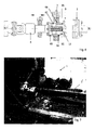
- Fig. 7 is a schematic view of a truck for use with demountable bodies, including an engine power takeoff and a stationary part of a clutch as shown in Fig. 1 and Fig. 2;
- Fig. 8 is a schematic view of a demountable body, having a hydraulic pump thereon, with a movable part of a clutch mounted thereon, such as the one shown in Fig. 3 and Fig. 4;
- Fig. 9 shows a possible embodiment of the means for horizontally displacing the body on the chassis of the truck; and
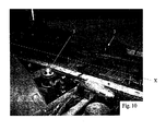
- Fig. 10 shows some of the means provided on a truck for raising the body and coupling the body after horizontally displacing the body on the chassis of the truck.
- The accompanying drawings show a
truck 1 that comprises achassis 2, extending along a longitudinal axis X, which defines a base plane n for receiving ademountable body 12, such as a concrete mixer. - The truck is equipped with means 3 for raising and lowering the
demountable body 12 with no change in the vehicle attitude. - The means 3 for raising and lowering the demountable body with no change in the vehicle attitude are known per se and will not be further described herein.
- The
truck 1 is further equipped withmeans 4 for horizontally displacing thedemountable body 12 on the base plane n along the longitudinal axis X, between a position in which thedemountable body 12 is anchored to thechassis 2 of the truck and a position in which the body is susceptible of being raised. - The
means 4 for displacing thebody 12 along the longitudinal axis X are also known per se and will not be further described herein. - The
structure 13 and thebody 12 can be anchored to thechassis 2 of the truck using conventional means, such as brackets and pins. - In the preferred embodiment, the means for displacing the
body 12 along the longitudinal axis X are separate from the means for raising and lowering thebody 12. - An
element 5 is provided, that rotates about an axis of rotation X1 parallel to the longitudinal axis X of the truck, and is integral with apower takeoff 30. - This rotating
element 5 has a plurality of projectingclaws 51 cincumferentially arranged about the axis of rotation X1 on a plane orthogonal to the plane of rotation X1. - The rotating
element 5 is the stationary part of a one-way claw clutch. - An important feature of the rotating
element 5 is that the projectingclaws 51 are substantially and/or generally sawtooth or right trapezoidal in shape. - This conformation optimizes torque transmission while reducing axial stresses.
- In the embodiment of the figures, the
rotating element 5 has a tubular portion 52 with projectingclaws 51 therein. - The tubular portion 52 facilitates mutual coupling of the stationary part and the movable part of the clutch, particularly when the two parts of the clutch are offset.
- In a possible embodiment (not shown), the
rotating element 5 is axially movable along the axis of rotation X1 relative to the chassis, against elastic return means. - This feature provided perfect coupling of the two parts of the clutch.
- The
demountable body 12 of the truck has asupport frame 13 extending along a longitudinal axis X' - which is designed to be coupled with achassis 2 of atruck 1. - The
support frame 13 of thebody 12 has a plurality of receptacles for the body to be raised, with no change of the vehicle attitude, using rods or vertical pins. - A plurality of anchor means 40 may be provided, such as brackets integral with the
frame 13 of thebody 12, which are aligned parallel to the longitudinal axis X' of the body. - An
element 9 is further provided, that rotates about an axis of rotation X1' parallel to the longitudinal axis X of the body, and is connected to a drivenshaft 6 mounted to at least one support 7 integral with thesupport frame 13 of thebody 12. - This rotating
element 9 has a plurality of projectingclaws 91 cincumferentially arranged about the axis of rotation X1' on a plane orthogonal to the plane of rotation X1'. - In the embodiment of the figures, the driven
shaft 6 is connected to the hydraulic power consuming unit by means of a universal joint (semi transmission). - The rotating
element 9 is the movable part of a claw clutch. - An important feature of the rotating
element 9 is that the projectingclaws 91 are also substantially and/or generally sawtooth or right trapezoidal in shape. - This claw shape allows easier coupling of the two parts of the clutch when the claws are not in the right mutual position or when one of the two parts of the clutch is rotated relative to the other part.
- The support 7 of the driven
shaft 6 may be a swivel bearing support or a support with damping material (such as resin). - This solution provides absorption of all the shocks acting upon the transmission system which includes the driven
shaft 6. - In the embodiment of the figure, the
rotating element 9 is axially movable along the axis of rotation X1' - relative to the driven shaft - against elastic return means 15. - This solution allows proper reliable coupling between the two parts of the clutch, while ensuring proper compression between the two parts of the clutch.
- For this purpose, the movable rotating
element 9 has ahub 92 slideably fitting into a hollow element or bushing 93. - In the embodiment of the figure, the
hub 92 has a pair of (diametrically opposite) longitudinal channels (95) in which keys are received, which are coupled withcorresponding channels 97 formed in thehollow element 93. - The
channels 97 act as guides for axial translation of thehub 92 whose stroke obviously depends on the length of thechannels 97. - Safety means 98 are also provided, such as a dowel, to prevent the
spring 15 from causing the movable rotatingelement 9 to be accidentally ejected from thehollow element 93. - In a possible embodiment, the elastic return means include a helical spring, partly inserted in a blind hole formed in the
hub 92, which is designed to operated under compression. - Using the above clutch system, the two rotating
members body 12 on thetruck 1. - The possibility of relative displacement of one of the two
members - It shall be noted that the claws of the rotating
elements - For easier connection between the
claws elements
Claims (11)
- A truck (1) comprising:- a chassis (2), extending along a longitudinal axis (X), which defines a base plane (n);- means (3) for raising and lowering a demountable body (12) with no change in the vehicle attitude,- means (4) for horizontally displacing a demountable body (12) on said base plane (X), between a position in which the demountable body (12) is anchored to the chassis (2) of the truck and a position in which said body (12) is susceptible of being raised;- an element (5) rotating about an axis of rotation (X1) parallel to said longitudinal axis (X), said rotating element (5) being integrally connected to a power takeoff (30) and having a plurality of projecting claws (51) circumferentially arranged about said axis of rotation (X1) on a plane orthogonal to said axis of rotation (X1);characterized in that said projecting claws (51) are substantially and/or generally sawtooth or right trapezoidal in shape.
- A truck as claimed in claim 1, wherein said rotating element (5) has a tubular portion (52) containing said projecting claws (51).
- A truck as claimed in claim 1 or 2, wherein said rotating element (5) is axially movable along said axis of rotation (X1) against elastic return means (15).
- A demountable body (12) for a truck, comprising:- a support frame (13) extending along a longitudinal axis (X');- a plurality of receptacles integral with said support frame (13), for said body (12) to be raised, with no change of the vehicle attitude, using rods or vertical pins;- fastener means for anchoring said body to the chassis of a truck;- an element (9) rotating about an axis of rotation (X1') parallel to said longitudinal axis (X'), said rotating element (5) being connected to a driven shaft (6) mounted to at least one support (7) integral with said support frame (13) of said body (12), said rotating element (9) having a plurality of projecting claws (91) circumferentially arranged about said axis of rotation (X1') on a plane orthogonal to said axis of rotation (X1'), wherein said projecting claws (91) are substantially sawtooth or right trapezoidal in shape.
- A body as claimed in claim 4, wherein said support (7) is a vibration damping support.
- A body as claimed in claim 4 or 5, wherein said rotating element (9) is axially movable along said axis of rotation (X1') relative to said driven shaft (6) against elastic return means (15).
- A combination of a truck as claimed in any one of claims 1 to 3, and a body as claimed in any one of claims 4 to 6.
- A one-way claw clutch, comprising:- a first rotating element (5), adapted to rotate about an axis (X1);- a second rotating element (9), connected to a shaft (6), which is adapted to rotate about an axis (X1') and to axially move along said axis (X1') relative to said shaft (6) against elastic return means (15).
- A clutch as claimed in claim 8, wherein said second movable rotating element (9) has a hub (92) slideably fitting into a hollow element (93) and wherein said elastic return means (15) are received in a blind hole formed in the hub (92), said elastic means (15) operating under compression.
- A clutch as claimed in claim 9, wherein said hub (92) has a pair of longitudinal channels (95) in which keys (96) are received, which are coupled with corresponding channels (97) formed in said hollow element (93).
- A clutch as claimed in claim 10, further comprising means (7) for damping the vibrations of said hollow element (93).
Applications Claiming Priority (1)
| Application Number | Priority Date | Filing Date | Title |
|---|---|---|---|
| ITMI20062043 ITMI20062043A1 (en) | 2006-10-24 | 2006-10-24 | AUTOMATIC FASTENING-RELEASE SYSTEM FOR TORQUE TRANSMISSIONS IN TRUCKS WITH DEMONTABLE BODYWORK |
Publications (1)
| Publication Number | Publication Date |
|---|---|
| EP1916147A1 true EP1916147A1 (en) | 2008-04-30 |
Family
ID=38947694
Family Applications (1)
| Application Number | Title | Priority Date | Filing Date |
|---|---|---|---|
| EP07020798A Withdrawn EP1916147A1 (en) | 2006-10-24 | 2007-10-24 | Automatic coupling/uncoupling system for torque transmission units in trucks having demountable bodies |
Country Status (2)
| Country | Link |
|---|---|
| EP (1) | EP1916147A1 (en) |
| IT (1) | ITMI20062043A1 (en) |
Cited By (4)
| Publication number | Priority date | Publication date | Assignee | Title |
|---|---|---|---|---|
| GB2459134A (en) * | 2008-04-11 | 2009-10-14 | Winton Engineering Ltd | Power take-off clutch with tooth faces having inclines of a different magnitude |
| DE102009016964A1 (en) * | 2009-04-14 | 2010-10-21 | Ffg Flensburger Fahrzeugbau Gmbh | Vehicle i.e. armored recovery vehicle, has removable drive shaft connecting hydraulic units with engine, and detachable multipolar electrical plug connection that is provided for supplying power and for controlling signals |
| EP2960094A1 (en) * | 2014-06-26 | 2015-12-30 | Pris-Mag S.r.l. | Torque transmission device for trucks having demountable or interchangeable bodies |
| US20190186550A1 (en) * | 2017-12-20 | 2019-06-20 | Ecycli Ltd. | Toothed disk coupling |
Citations (6)
| Publication number | Priority date | Publication date | Assignee | Title |
|---|---|---|---|---|
| GB798946A (en) * | 1955-04-01 | 1958-07-30 | Thomas Richard Jones | Improvements in or relating to starting devices for internal combustion and other engines |
| GB1457480A (en) * | 1974-03-16 | 1976-12-01 | Deere & Co | Combine harvesters |
| US4090725A (en) * | 1975-03-19 | 1978-05-23 | Ste Fiat France S.A. | Devices for automatically coupling implements to self-propelled vehicles |
| EP0083033B1 (en) * | 1981-12-24 | 1986-04-23 | Ernst Conrad | Coupling for a power take-off |
| EP0490365A1 (en) * | 1990-12-13 | 1992-06-17 | Emil Dautel Gmbh | Transport vehicle with interchangeable body |
| US5788473A (en) * | 1996-12-10 | 1998-08-04 | Ingersoll-Dresser Pump Company | Integral close coupling for a rotary gear pump |
-
2006
- 2006-10-24 IT ITMI20062043 patent/ITMI20062043A1/en unknown
-
2007
- 2007-10-24 EP EP07020798A patent/EP1916147A1/en not_active Withdrawn
Patent Citations (6)
| Publication number | Priority date | Publication date | Assignee | Title |
|---|---|---|---|---|
| GB798946A (en) * | 1955-04-01 | 1958-07-30 | Thomas Richard Jones | Improvements in or relating to starting devices for internal combustion and other engines |
| GB1457480A (en) * | 1974-03-16 | 1976-12-01 | Deere & Co | Combine harvesters |
| US4090725A (en) * | 1975-03-19 | 1978-05-23 | Ste Fiat France S.A. | Devices for automatically coupling implements to self-propelled vehicles |
| EP0083033B1 (en) * | 1981-12-24 | 1986-04-23 | Ernst Conrad | Coupling for a power take-off |
| EP0490365A1 (en) * | 1990-12-13 | 1992-06-17 | Emil Dautel Gmbh | Transport vehicle with interchangeable body |
| US5788473A (en) * | 1996-12-10 | 1998-08-04 | Ingersoll-Dresser Pump Company | Integral close coupling for a rotary gear pump |
Cited By (6)
| Publication number | Priority date | Publication date | Assignee | Title |
|---|---|---|---|---|
| GB2459134A (en) * | 2008-04-11 | 2009-10-14 | Winton Engineering Ltd | Power take-off clutch with tooth faces having inclines of a different magnitude |
| DE102009016964A1 (en) * | 2009-04-14 | 2010-10-21 | Ffg Flensburger Fahrzeugbau Gmbh | Vehicle i.e. armored recovery vehicle, has removable drive shaft connecting hydraulic units with engine, and detachable multipolar electrical plug connection that is provided for supplying power and for controlling signals |
| DE102009016964B4 (en) * | 2009-04-14 | 2021-04-08 | Ffg Flensburger Fahrzeugbau Gmbh | Vehicle with an engine and a hydraulic unit operated by the engine |
| DE102009016964C5 (en) | 2009-04-14 | 2024-06-06 | Ffg Flensburger Fahrzeugbau Gmbh | Vehicle with an engine and a hydraulic unit driven by the engine |
| EP2960094A1 (en) * | 2014-06-26 | 2015-12-30 | Pris-Mag S.r.l. | Torque transmission device for trucks having demountable or interchangeable bodies |
| US20190186550A1 (en) * | 2017-12-20 | 2019-06-20 | Ecycli Ltd. | Toothed disk coupling |
Also Published As
| Publication number | Publication date |
|---|---|
| ITMI20062043A1 (en) | 2008-04-25 |
Similar Documents
| Publication | Publication Date | Title |
|---|---|---|
| US6446937B1 (en) | Removable gear drive for mechanical jack | |
| US20070008816A1 (en) | Mixer | |
| EP1916147A1 (en) | Automatic coupling/uncoupling system for torque transmission units in trucks having demountable bodies | |
| US20170001603A1 (en) | Trailer landing gear apparatus | |
| US20070210289A1 (en) | Powered drive for jack | |
| JP2003276565A (en) | Electric steering lock device | |
| JP6956275B2 (en) | Vehicle-side and accessory-side PTO-connected devices and PTO-connected devices with two PTO-connected devices | |
| US20060170189A1 (en) | Arrangement of a motor on a support winch | |
| WO1998040157A1 (en) | Mixer for container | |
| US7429061B2 (en) | Drive mechanism and method of operating the same | |
| CN101769279A (en) | Locking device | |
| CN106574667A (en) | Emergency manual for shafts manufactured to rotate | |
| KR102018599B1 (en) | Steering column assembly | |
| US20150175136A1 (en) | System and device for mechanically extending and retracting landing gear of a semitrailer or a chassis | |
| WO2006098822A1 (en) | Speed crank locking device for trailer landing gear assembly | |
| US20020162936A1 (en) | Guide bar adapter, and a guide bar assembly | |
| US20050137020A1 (en) | Controlled collapsible drive line arrangement | |
| EP2371637A2 (en) | Electric drive unit for a corner steady | |
| CA2329528C (en) | Cylinder equipment for producing printing plates | |
| CN209908401U (en) | Device for upward drilling and installing anchor bolt into hole | |
| CN114179709B (en) | Locking and unlocking device for vehicle-mounted self-adaptive cylindrical heavy load | |
| EP2345556A1 (en) | Transport vehicle with a locking device | |
| CN118849680A (en) | Trailer towing device | |
| US8882133B2 (en) | Support device for a semi-trailer | |
| CN113602985A (en) | Slope fixing mechanism based on crane and operation method thereof |
Legal Events
| Date | Code | Title | Description |
|---|---|---|---|
| PUAI | Public reference made under article 153(3) epc to a published international application that has entered the european phase |
Free format text: ORIGINAL CODE: 0009012 |
|
| AK | Designated contracting states |
Kind code of ref document: A1 Designated state(s): AT BE BG CH CY CZ DE DK EE ES FI FR GB GR HU IE IS IT LI LT LU LV MC MT NL PL PT RO SE SI SK TR |
|
| AX | Request for extension of the european patent |
Extension state: AL BA HR MK RS |
|
| STAA | Information on the status of an ep patent application or granted ep patent |
Free format text: STATUS: THE APPLICATION HAS BEEN WITHDRAWN |
|
| 17P | Request for examination filed |
Effective date: 20081030 |
|
| 18W | Application withdrawn |
Effective date: 20081114 |