EP1916059A2 - Eyeglass lens processing apparatus - Google Patents
Eyeglass lens processing apparatus Download PDFInfo
- Publication number
- EP1916059A2 EP1916059A2 EP07020843A EP07020843A EP1916059A2 EP 1916059 A2 EP1916059 A2 EP 1916059A2 EP 07020843 A EP07020843 A EP 07020843A EP 07020843 A EP07020843 A EP 07020843A EP 1916059 A2 EP1916059 A2 EP 1916059A2
- Authority
- EP
- European Patent Office
- Prior art keywords
- lens
- cup
- processing apparatus
- eyeglass lens
- eye
- Prior art date
- Legal status (The legal status is an assumption and is not a legal conclusion. Google has not performed a legal analysis and makes no representation as to the accuracy of the status listed.)
- Granted
Links
Images



Classifications
-
- B—PERFORMING OPERATIONS; TRANSPORTING
- B24—GRINDING; POLISHING
- B24B—MACHINES, DEVICES, OR PROCESSES FOR GRINDING OR POLISHING; DRESSING OR CONDITIONING OF ABRADING SURFACES; FEEDING OF GRINDING, POLISHING, OR LAPPING AGENTS
- B24B13/00—Machines or devices designed for grinding or polishing optical surfaces on lenses or surfaces of similar shape on other work; Accessories therefor
- B24B13/01—Specific tools, e.g. bowl-like; Production, dressing or fastening of these tools
-
- B—PERFORMING OPERATIONS; TRANSPORTING
- B24—GRINDING; POLISHING
- B24B—MACHINES, DEVICES, OR PROCESSES FOR GRINDING OR POLISHING; DRESSING OR CONDITIONING OF ABRADING SURFACES; FEEDING OF GRINDING, POLISHING, OR LAPPING AGENTS
- B24B41/00—Component parts such as frames, beds, carriages, headstocks
- B24B41/06—Work supports, e.g. adjustable steadies
- B24B41/061—Work supports, e.g. adjustable steadies axially supporting turning workpieces, e.g. magnetically, pneumatically
- B24B41/062—Work supports, e.g. adjustable steadies axially supporting turning workpieces, e.g. magnetically, pneumatically between centres; Dogs
-
- B—PERFORMING OPERATIONS; TRANSPORTING
- B24—GRINDING; POLISHING
- B24B—MACHINES, DEVICES, OR PROCESSES FOR GRINDING OR POLISHING; DRESSING OR CONDITIONING OF ABRADING SURFACES; FEEDING OF GRINDING, POLISHING, OR LAPPING AGENTS
- B24B13/00—Machines or devices designed for grinding or polishing optical surfaces on lenses or surfaces of similar shape on other work; Accessories therefor
- B24B13/06—Machines or devices designed for grinding or polishing optical surfaces on lenses or surfaces of similar shape on other work; Accessories therefor grinding of lenses, the tool or work being controlled by information-carrying means, e.g. patterns, punched tapes, magnetic tapes
-
- B—PERFORMING OPERATIONS; TRANSPORTING
- B24—GRINDING; POLISHING
- B24B—MACHINES, DEVICES, OR PROCESSES FOR GRINDING OR POLISHING; DRESSING OR CONDITIONING OF ABRADING SURFACES; FEEDING OF GRINDING, POLISHING, OR LAPPING AGENTS
- B24B9/00—Machines or devices designed for grinding edges or bevels on work or for removing burrs; Accessories therefor
- B24B9/02—Machines or devices designed for grinding edges or bevels on work or for removing burrs; Accessories therefor characterised by a special design with respect to properties of materials specific to articles to be ground
- B24B9/06—Machines or devices designed for grinding edges or bevels on work or for removing burrs; Accessories therefor characterised by a special design with respect to properties of materials specific to articles to be ground of non-metallic inorganic material, e.g. stone, ceramics, porcelain
- B24B9/08—Machines or devices designed for grinding edges or bevels on work or for removing burrs; Accessories therefor characterised by a special design with respect to properties of materials specific to articles to be ground of non-metallic inorganic material, e.g. stone, ceramics, porcelain of glass
- B24B9/14—Machines or devices designed for grinding edges or bevels on work or for removing burrs; Accessories therefor characterised by a special design with respect to properties of materials specific to articles to be ground of non-metallic inorganic material, e.g. stone, ceramics, porcelain of glass of optical work, e.g. lenses, prisms
- B24B9/148—Machines or devices designed for grinding edges or bevels on work or for removing burrs; Accessories therefor characterised by a special design with respect to properties of materials specific to articles to be ground of non-metallic inorganic material, e.g. stone, ceramics, porcelain of glass of optical work, e.g. lenses, prisms electrically, e.g. numerically, controlled
-
- B—PERFORMING OPERATIONS; TRANSPORTING
- B24—GRINDING; POLISHING
- B24B—MACHINES, DEVICES, OR PROCESSES FOR GRINDING OR POLISHING; DRESSING OR CONDITIONING OF ABRADING SURFACES; FEEDING OF GRINDING, POLISHING, OR LAPPING AGENTS
- B24B9/00—Machines or devices designed for grinding edges or bevels on work or for removing burrs; Accessories therefor
- B24B9/02—Machines or devices designed for grinding edges or bevels on work or for removing burrs; Accessories therefor characterised by a special design with respect to properties of materials specific to articles to be ground
- B24B9/06—Machines or devices designed for grinding edges or bevels on work or for removing burrs; Accessories therefor characterised by a special design with respect to properties of materials specific to articles to be ground of non-metallic inorganic material, e.g. stone, ceramics, porcelain
- B24B9/16—Machines or devices designed for grinding edges or bevels on work or for removing burrs; Accessories therefor characterised by a special design with respect to properties of materials specific to articles to be ground of non-metallic inorganic material, e.g. stone, ceramics, porcelain of diamonds; of jewels or the like; Diamond grinders' dops; Dop holders or tongs
Definitions
- a lens held (chucked) by lens chucks is rough-processed by a roughing grindstone. Thereafter, the lens is finished to process by a finishing grindstone (refer to, for example, USP6283826 ( JP-A-11-333684 ).).
- a finishing grindstone (refer to, for example, USP6283826 ( JP-A-11-333684 ).).
- FIG. 1 shows an overview of an eyeglass lens processing apparatus and a cup attaching apparatus according to the invention.
- a carriage portion 100 is mounted on a base 170. Further, the processed lens LE is chucked by lens chucks 102L, 102R provided to a carriage 101 constituting the carriage portion 100. A peripheral edge of the lens LE is processed by controlling distances of the chucks 102L, 102R relative to a grindstone group 162 attached to a grindstone spindle 161 and rotated by a motor 160.
- the grindstone group 162 is constituted by a roughing grindstone for plastic 162a, a bevel-finishing and plane-finishing grindstone 162b and a polishing-finishing grindstone 162c, a roughing grindstone for glass 162d.
- the support base 140 is fixed with shafts 156, 157 extended in a Y-axis direction (a direction of varying distances between axes of the lens chucks 102R, 102L and the grindstone spindle 161).
- the carriage 101 is mounted on the support base 140 along the shafts 156, 157 movably in the Y-axis direction.
- the support base 140 is fixed with a Y-axis moving motor 150. Rotation of the motor 150 is transmitted to a ball screw 155 extended in the Y-axis direction. Further, the carriage 101 is moved in the Y-axis direction by rotating the ball screw 155.
- cup holder 31a provided at the cup attaching apparatus 1 is formed with an inserting hole and a key similar to the cup holder 130. Shapes thereof are similar to those of the cup holder 130, and therefore, an explanation thereof will be omitted.
- the upper portion of the screen is displayed with left and right selecting keys 214R, 214L as means for selecting which of left and right lenses the lens LE to be processed is.
- a display area of the key 214R is displayed by red color.
- a color at inside of the target lens shape diagram FTR for the right eye is displayed (including a case of approximate color).
- insides of the key 214L for selecting the left eye and the target lens shape diagram FTL for the left eye are fixed by a color the same as that of a background of the screen.
- the operator confirms the colors and the colors of the cups 25R, 25L fixed to the lens LE. Thereby, it can visually be confirmed easily which is the lens LE to be held by the lens chuck shafts 102R, 102L. That is, when the right eye is selected, insides of the display area of the selected key 214R and the target lens shape diagram FTR for the right eye are displayed by red color. Therefore, the lens LE attached with the cup 25R of the corresponding red color may be mounted to the cup holder 130 of the lens chuck shaft 102L. When the left eye is selected, insides of the display area of the selected key 214L and the target lens shape diagram FTL are displayed by green color.
- the lens LE attached with the cup 25L of green color in correspondence with the color may be mounted to the cup holder 130.
- a failure of mistaking left or right of the lenses LE can significantly be reduced.
- display colors of insides of the display areas of the selected keys 214R, 214L and the target lens shape diagrams FTR, FTL as the information of identifying left and right lenses displayedbased on selecting left and right lenses are displayed in correspondence with coloring the cups 25R, 25L. Therefore, optical recognizability can considerably be improved and the left and right lenses can easily be identified.
Landscapes
- Engineering & Computer Science (AREA)
- Mechanical Engineering (AREA)
- Chemical & Material Sciences (AREA)
- Ceramic Engineering (AREA)
- Inorganic Chemistry (AREA)
- Grinding And Polishing Of Tertiary Curved Surfaces And Surfaces With Complex Shapes (AREA)
- Eyeglasses (AREA)
Abstract
Description
- The present invention relates to an eyeglass lens processing apparatus for processing a peripheral edge of an eyeglass lens.
- According to an eyeglass lens processing apparatus, a lens held (chucked) by lens chucks is rough-processed by a roughing grindstone. Thereafter, the lens is finished to process by a finishing grindstone (refer to, for example,
USP6283826 (JP-A-11-333684 USP6798501 (JP-A-2001-62688 - Meanwhile, in processing the lens, when powers (spherical power, cylindrical power, axial angle) of left and right lenses differ from each other, it is important to process the lenses without mistaking the left and the right lenses. Therefore, an operator (processor) pays close attention so as not to mistake the left and right lenses. In correspondence therewith, marks or the like for identifying the left and right lenses are marked on surfaces of the lenses by a pen or the like.
Further, there is also proposed a cup capable of identifying left and right lenses by a cup having a difference in presence/absence of forming a recess portion or a hole at a base portion of the cup (refer to, for example,JP-A-8-252754 - However, according to the method of marking the mark or the like by the pen on the surfaces of the lenses, an operation of marking a mark and an operation of erasing the mark are needed. The operations take time and labor for the operator. Further, in a case of a lens coated by a water-repellant coating, a mark cannot be applied thereto.
The method of identifying the lenses by forming the recess portion or the hole at the base portion of the cup, shapes of the left and right cups cannot significantly be changed. Therefore, the recess portion or the hole is small, and therefore, the identification is not facilitated at a glance. - It is a technical object of the invention to provide an eyeglass lens processing apparatus capable of further reducing a mistake of left and right glasses.
- In order to achieve the above object, the present invention is characterized by having the following arrangement.
- (1) An eyeglass lens processing apparatus for processing a peripheral edge of an eyeglass lens, comprising:
- data inputting means for inputting a target lens shape data and a layout data;
- a cup for a left eye and a cup for a right eye to which identifying information for identifying the cup for the left eye and the cup for the right eye, which can be visually identified by a processor, is applied; and
- displaying means for displaying identifying information the same as the identifying information applied to the cup for the left eye or the right eye based on data inputted to the data inputting means.
- (2) The eyeglass lens processing apparatus according to (1) further comprising a cup attaching apparatus for attaching, to the eyeglass lens, the cup constituting an auxiliary piece for attaching the eyeglass lens to the eyeglass lens processing apparatus,
wherein the cup attaching apparatus includes left and right selecting means for selecting whether the lens attached to the cup is for the left eye or for the right eye, and displaying means for displaying identifying information the same as the identifying information applied to the cup for the left eye or the right eye selected by the left and right selecting means. - (3) The eyeglass lens processing apparatus according to (1), wherein the identifying information identified visually by the processor is applied at least to a flange portion.
- (4) The eyeglass lens processing apparatus according to (1), wherein the identifying information identified visually by the processor is color information.
-
- Fig.1 is a view for explaining an overview of an eyeglass lens processing apparatus and a cup attaching apparatus;
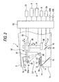
- Fig. 2 is a view for explaining an optical system, a blocking mechanism portion and a control system arranged at a cup attaching apparatus;
- Fig.3 is a view for explaining an inner portion of an eyeglass lens processing apparatus;
- Fig.4 is a diagram for explaining a control system of a processing apparatus;
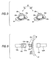
- Fig.5 is a view for explaining a cup;
- Fig.6 is a view for explaining a cup holder provided to a lens chuck;
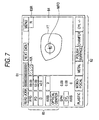
- Fig.7 is a view for explaining an input screen of a cup attaching apparatus; and
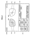
- Fig.8 is a view for explaining an input screen of a processing apparatus.
- An embodiment of the invention will be explained in reference to the drawings as follows. Fig. 1 shows an overview of an eyeglass lens processing apparatus and a cup attaching apparatus according to the invention.
- A constitution of a cup attaching apparatus 1 will be explained in reference to Fig. 1 and Fig. 2. Fig. 2 shows an optical system, a blocking mechanism portion and a control system arranged at the apparatus 1.
- A
base 1a is disposed on a lower side of the apparatus 1. An upper surface of thebase 1a is attached with a lens table 10 made of transparent acrylic resin in a circular shape by way of aring member 11. 3 pieces ofsupport pins 12 are provided above the lens table 10 centering on a reference axis L1 of attaching a cup at equal intervals for supporting a lens LE. - A front surface of the
base 1a is arranged with aswitch 2a for operating a blocking mechanism portion 30 (mentioned later). Further, the front surface is arranged with aswitch 2b for selecting left and right lenses. A pertinent space is ensured between a lower surface of anupper portion 1b projected to a front side of the apparatus 1 and thebase 1a. The space is for the operator to hold the lens LE by the hand to move on the lens table 10 and for acup 25 attached to a front end of acup attaching arm 31 to be able to move up and down. - The apparatus 1 is provided with a detection
optical system 9 for illuminating the lens LE, for detecting an optical center and an axial angle or the like of the lens LE. A constitution of the detectionoptical system 9 will be shown as follows. - An
illumination light source 20 is arranged on a rear side of a vicinity of the lens table 10. Aconcave mirror 21 is provided with a mirror curved face for shaping illuminating light from theillumination light source 20 into a substantially parallel light flux having a diameter one size larger than that of the lens LE. Further, the substantially parallel light flux is projected along the reference axis L1. - A center of the lens table 10 is formed with an
index portion 13 having a predetermined pattern centering on the reference axis L1. Theindex portion 13 comprises dot indexes arranged in a lattice-like shape. The dot index has a size of a diameter of 0.3mm. Further, the indexes are arranged at a pitch interval of 0.3mm in a range of 20mm square centering on the reference axis L1. A lower side of the lens table 10 is arranged with ascreen plate 14 made by a semitransparent material of frosted glass or the like. A light flux transmitting through the lens LE illuminates theindex portion 13 on the table 5. A total image of the lens LE and a dot index image subjected to prism operation of the lens LE are projected onto thescreen plate 14. Further, amirror 15 is arranged on a lower side of thescreen plate 14. Further, afirst CCD camera 17 is arranged on a lower side of thescreen plate 14. Thefirst CCD camera 17 is provided with a lens for taking an image by enlarging only a center region centering on the reference axis L1 to be able to detect the index image projected to thescreen plate 14. Ahalf mirror 16 is arranged on an optical path between themirror 15 and thefirst CCD camera 17. Further, asecond CCD camera 18 is provided in a reflecting direction of themirror 16. Thesecond CCD camera 18 is provided with a lens for taking a total image of the lens LE projected to thescreen plate 14. - An explanation will be given of a method of calculating an optical center position and an axial angle of the lens LE from the image of the dot index image provided by the
first CCD camera 17. When the lens LE is not mounted, the dot index of theindex portion 13 is illuminated by a parallel light flux. Therefore, the index image is projected to thescreen plate 14 as it is. When the lens LE having refracting power is mounted, a position of the dot image disposed right below the vicinity of the optical center of the lens LE stays the same regardless of presence/absence of the lens LE. However, a coordinate position of the dot image of a portion which is not disposed at the optical center of the lens LE is moved by a prism operation. Therefore, in order to detect the optical center, a change in the coordinate position of each dot image in the state of mounting the lens LE is grasped relative to the coordinate position of each dot image in a state of absence of the lens LE. It is calculated to which position each dot image is diverged or converged centering thereon. The center of diverging or converging constitutes the optical center. - Further, when the lens LE is provided with an astigmatism degree, each dot image is moved in a direction of being proximate to (or a direction of being remote from) a generatrix of the lens. Therefore, the axial angle is detected by investigating in which direction each dot image is moved relative to the coordinate position of each dot image in the state of absence of the lens LE.
- In Fig. 2, the
blocking mechanism portion 30 includes thearm 31 arranged with acup holder 31a mounted with a base portion of acup 25, a Y axisdirection moving unit 32 for moving thearm 31 in Y axis direction (refer to Fig.2), a Z axisdirection moving unit 34 for moving thearm 31 in an up and down direction (Z axis direction) along with theunit 32, and an X axisdirection moving unit 36 for moving thearm 31 in a left and right direction (X axis direction) relative to a front surface of the apparatus 1 along with theunit 34. The movingunits cup holder 31a is attached to thearm 31 rotatably centering on an axis extended in an up and down direction. The Y axisdirection moving unit 32 is arranged with adrive unit 38 arranged with a motor for rotating thecup holder 31a. A drive force of rotation of thedrive unit 38 is transmitted to thecup holder 31a by way of a rotation transmitting mechanism (constituted by a gear, a rotating shaft and the like) arranged at inside of thearm 31. By rotating thecup holder 31a centering on the up and down shaft, an angle of thecup 25 is adjusted in accordance with an astigmatism viewing angle of the lens LE. - The rear side of the apparatus 1 is arranged with an eyeglass frame
shape measuring unit 5. An upper surface of the apparatus 1 is arranged with a colorliquid crystal display 3 for displaying a lens image taken by thesecond CCD camera 18 and various information. Furthermore, anoperation switch portion 4 of theunit 5 is also arranged to the surface. Thedisplay 3 is provided with a touch panel function. - The
unit 5, thedisplay 3, theCCD cameras control portion 50. Thecontrol portion 50 calculates the optical center position and the axial angle of the lens LE based on an output signal from theCCD camera 17. Furthermore, thecontrol portion 50 controls to drive respective units and display thedisplay 3 or the like. - A constitution of an eyeglass
lens processing apparatus 200 will be explained in reference to Fig.1 and Fig.3. Fig.3 shows a processing mechanism at inside of the apparatus. - A
carriage portion 100 is mounted on abase 170. Further, the processed lens LE is chucked by lens chucks 102L, 102R provided to acarriage 101 constituting thecarriage portion 100. A peripheral edge of the lens LE is processed by controlling distances of thechucks grindstone group 162 attached to agrindstone spindle 161 and rotated by amotor 160. Thegrindstone group 162 is constituted by a roughing grindstone for plastic 162a, a bevel-finishing and plane-finishinggrindstone 162b and a polishing-finishinggrindstone 162c, a roughing grindstone forglass 162d. - The
lens chuck shaft 102L is held by aleft arm 101L of thecarriage 101 and thelens chuck 102R is held by aright arm 101R respectively rotatably and coaxially. Thelens chuck shaft 102R is moved to a side of thelens chuck 102L by amotor 110 attached to theright arm 101R. Further, the lens LE is held by two of the lens chucks 102R, 102L. Further, the two lens chucks 102R, 102L are rotated by amotor 120 attached to theleft arm 101L by way of a rotation transmitting mechanism of a gear or the like in synchronism with each other. A front end side of thelens chuck shaft 102L is fixed with acup holder 130 mounted with abase portion 25a of thecup 25. A front end side of thelens chuck 102R is fixed with alens holding member 135 brought into contact with a back surface of the lens LE (refer to Fig. 6) . - The
carriage 101 is mounted on an X-axis movingsupport base 140 alongshafts grindstone spindle 161. A back portion of thesupport base 140 is attached with a ball screw extended in parallel with the shaft 103 (not illustrated). The ball screw is attached to a rotating shaft of anX-axis moving motor 145. Further, thecarriage 101 is moved in an X-axis direction along with thesupport base 140 by rotating themotor 145. - Further, the
support base 140 is fixed withshafts carriage 101 is mounted on thesupport base 140 along theshafts support base 140 is fixed with a Y-axis moving motor 150. Rotation of themotor 150 is transmitted to aball screw 155 extended in the Y-axis direction. Further, thecarriage 101 is moved in the Y-axis direction by rotating theball screw 155. - In Fig.3, this side of the
processing apparatus 200 is arranged with achamfering mechanism portion 180. An upper side of thecarriage 101 is provided with edge path position measuring portions (lens shape measuring portions) 300F, 300R. A rear side of thecarriage portion 100 is arranged with a boring andgrooving mechanism portion 190. Well-known constitutions thereof are used. Therefore, an explanation thereof will be omitted here. - In Fig.1, an upper surface of the
processing apparatus 200 is arranged with acolor display 210 having a touch panel function, anoperation switch panel 220,LED 230R of red color andLED 230L of green color as displaying means for displaying information of identifying left and right lenses. Adoor 201 is arranged at the upper surface of the processing apparatus 1. - Fig.4 is a block diagram for explaining a control system of the
processing apparatus 200. Acontrol portion 250 is connected with thedisplay 210, thepanel 220,LEDs control portion 250. Thereby, data are transmitted and received between the cup attaching apparatus 1 and theprocessing apparatus 200. - Fig.5 is a view for explaining the
cup 25 as a jig fixed to the lens LE. Fig.6 is a view for explaining a constitution of thecup holder 130 provided with thelens chuck shaft 102L and fitting thecup 25 to theholder 130. - The
cup 25 is used by being differentiated to acup 25R fixed to a lens for the right eye and acup 25L fixed to a lens for the left eye. Although shapes of thecup 25R and thecup 25L are the same, colors applied thereto differ from each other in order to identify left and right lenses at a glance. Therefore, in Fig. 5 and Fig. 6, the same notations are attached to constituent elements of thecup 25R and thecup 25L. Thecups base portion 25a inserted into an insertinghole 131a of thecup holder 130 and aflange 26. Thebase portion 25a is formed with akey groove 25b. Further, thekey groove 25b is fitted to a key 131b formed at the insertinghole 131a. Thereby, an angle of thechuck 102L (102R) relative to the lens LE can be maintained constant. Further, thebase portion 25a is formed with anotch 25c for determining a position in an up and down direction of the lens. Theflange 26 is formed with a recessed and projectedportion 26a around thebase portion 25a in order to alleviate a shift in a rotational direction relative to thecup holder 130. In accordance therewith, also an end portion of thecup holder 130 is formed with a recessed and projected portion fitted to the recessed and projectedportion 26a. After mounting thebase portion 25a of thecup cup holder 130, by moving thelens chuck 102R to the side of the lens LE, thelens holding member 135 is brought into contact with a rear surface of the lens. Thereby, the lens LE is held by the two lens chucks 102R, 102L. - Further, also the
cup holder 31a provided at the cup attaching apparatus 1 is formed with an inserting hole and a key similar to thecup holder 130. Shapes thereof are similar to those of thecup holder 130, and therefore, an explanation thereof will be omitted. - With regard to different colors applied to the
cup 25R and thecup 25L, it is preferable that a difference therebetween is easy to visually understand. According to the embodiment, thewhole cup 25R is formed by red color and thewhole cup 25L is formed by green color. In a case of integrally molding thecups cups flange portion 26 which is provided with a wide area and is easy to identify. - Further, according to the embodiment, the
flange portion 26 is provided with a size larger than a diameter of the cup holder 130 (31a). In this case, even after thebase portion 25a is mounted to the cup holder 130 (31a), theflange portion 26 is exposed to outside. Therefore, an operator can easily identify a difference of colors. An end portion of theflange portion 26 is formed by a thickness of about 2mm. Therefore, when the colors are applied in a thickness direction (side surface) of theflange portion 26, the colors can easily be confirmed from the side surface even after mounting thecups - Next, an explanation will be given of operation of the cup attaching apparatus 1 and the
processing apparatus 200 using the above-describedcups cups - A target lens shape data measured by the eyeglass frame
shape measuring unit 5 is stored to a memory 6. Thedisplay 3 is displayed with an input screen as shown by Fig. 7 . The screen displays that it is necessary to input an operation number (JOB number) for controlling a pair of left and right lenses LE. Further, an operator inputs the operation number by operating a numerical keypad displayed by depressing an operationnumber input column 61. Further, by operating respective keys of a processingcondition selecting column 62, processing conditions of a material of a lens, a kind of a lens (monofocal lens, bifocal lens or the like), a processing mode and the like are inputted. A layout data can be inputted by operating respective keys of alayout input column 65. The target lens shape data, the processing conditions and the like are stored to thememory 51 in relation to the operation number. - Further, the operator selects which of left and right lenses the lens LE is by left and right selecting
keys switch 2b. Here, an explanation will be given of a case of selecting a lens for the right eye. At this occasion, a display area of the key 63R is displayed by red color of the same color (including also a case of approximate color) in correspondence with red color applied to thecup 25R by thecontrol portion 50 based on a selection signal. The key 63L on a side of not being selected is displayed by a color the same as that of a background of alayout screen 64. On the other hand, when a lens for the left eye is selected, by thecontrol portion 50, a display area of the key 63L is displayed by green color of the same color (including also a case of approximate color) in correspondence with green color applied to thecup 25L. In this way, the display areas of the key 63R and the key 63L on thedisplay 3 are used as left and right displaying means for displaying information of identifying left and right lenses by colors in correspondence with thecups keys cups cup 25R of red color is attached to thecup holder 31a. Further, when the glass for the left eye is selected, thecup 25L of green color is attached to thecup holder 31a. - Further, the color is applied also to the portion of the
flange portion 26. Therefore, the color of theflange portion 26 can optically be confirmed even after mounting thecup cup holder 31a. Further, by the corresponding relationship with the display colors for identifying left and right lenses of thedisplay 210, it can easily be confirmed which of left andright cups holder 31a. - Further, means for displaying the information of identifying left and right glasses by colors in correspondence with colors of left and right cups is not limited to means for changing the display colors of the key 63R and the key 63L. For example, there may be adopted also a method of totally or partially changing the color of the background displayed on the
display 3. The background of thelayout screen 64 may be displayed by red color when the lens for the right eye is selected and displayed by green color when the lens for the left eye is selected. By displaying the color in correspondence with the color of the selected cup by a wide area, a situation of selecting left and right lenses becomes visually easy to grasp. Further, the display of the information of identifying left and right lenses in correspondence with the colors of the cups is not limited to the display of thedisplay 3. Other display may be provided. For example,LED 53R of red color andLED 53L of green color may be arranged at vicinities of theswitches LED 53R of red color is lighted in correspondence with a selecting signal. Further, when the lens for the left eye is selected,LED 53L of green color is lighted in correspondence with a selecting signal thereof. - Inputting a layout data will be explained. The operator can input the layout data of FED (frame pupillary distance), PD (pupillary distance), a height of an optical center of a lens relative to a geometrical center of a target lens shape and the like. Further, an astigmatism axis angle of a prescription data of the lens LE can be inputted. Further, it can be selected whether a block center of a lens is an optical center or a frame center (geometrical center of a target lens shape).
- Attaching cups to the left and right lenses LE will be explained. For example, an explanation will be given of a case of selecting the lens for the left eye by the key 63L. First, the operator mounts a center portion of the lens LE for the left eye at a vicinity of a center of three pieces of the support pins 12. Then, the index image projected to the
screen plate 14 is taken by thefirst CCD camera 17. Further, the optical center and the astigmatism axis direction of the lens LE are detected by thecontrol portion 50. Thelayout screen 64 is displayed with an optical center mark MFO based on the detected optical center. The operator can carry out an alignment by moving the lens LE by constituting a reference by the cup attaching center of the reference axis L1. According to the embodiment, instead of moving the lens LE, thearm 31 of theblocking mechanism portion 30 is moved three-dimensionally by being controlled by thecontrol portion 50 and thecup holder 31a is rotated to thereby automatically change the attaching angle of the cup. - When the
switch 2a is depressed, thecontrol portion 50 moves thearm 31 by controlling respective moving units of themechanism portion 30 based on the optical center of the lens, the layout data and the like. Further, thecontrol portion 50 rotates thecup 25L mounted to thecup holder 31a. Further, when the alignment position is determined, thecontrol portion 50 moves down thearm 31. Thereby, thecup 25L is fixed to the surface of the lens LE. In this way, the operator attaches thecups cups cup 25L (25R) by interposing an adhering double surfaces tape therebetween. However, the invention is not limited thereto but a cup formed with theflange portion 26 by adhering rubber will do. - Next, an explanation will be given of processing of a lens by the
processing apparatus 200. Fig. 8 shows an example of a data input screen displayed on thedisplay 210. The operator inputs the operation number by the numerical keypad displayed by depressing an operationnumber input column 212. Thereafter, a target lens shape data and a layout data or the like in correspondence with the operation number and the like are called from thememory 51 of the cup attaching apparatus 1 by thecontrol portion 250. Further, the data are stored to thememory 251 on the side of theprocessing apparatus 200. Respective display columns at a lower portion of the screen are set based on the called layout data and processing condition data and the like. Further, the upper portion of the screen is displayed with a target lens shape FTR for the right eye and a target lens shape FTL for the left eye. Further, the geometrical centers FC of respective target lens shapes and optical centers MFO are diagrammatically displayed. Further, the layout data, and the processing condition data can also be inputted on the side of theprocessing apparatus 200. - In Fig.8, the upper portion of the screen is displayed with left and right selecting
keys 214R, 214L as means for selecting which of left and right lenses the lens LE to be processed is. When the operator depresses the key 214R for the right eye, by controlling to display thedisplay 210 by thecontrol portion 250, a display area of the key 214R is displayed by red color. Further, a color at inside of the target lens shape diagram FTR for the right eye is displayed (including a case of approximate color). In a state of selecting the right eye, insides of the key 214L for selecting the left eye and the target lens shape diagram FTL for the left eye are fixed by a color the same as that of a background of the screen. On the other hand, when the key 214L for the left eye is depressed, a display area of the key 214L is displayed by green color. Simultaneously therewith, the color at inside of the target lens shape diagram FTL for the left eye is displayed by green color (including also a case of approximate color). Further, in a state of selecting the left eye, insides of the key 214R for selecting the right eye and the target lens shape diagram FTR for the right eye are fixed by a color the same as that of the background of the screen. - The operator confirms the colors and the colors of the
cups lens chuck shafts cup 25R of the corresponding red color may be mounted to thecup holder 130 of thelens chuck shaft 102L. When the left eye is selected, insides of the display area of the selected key 214L and the target lens shape diagram FTL are displayed by green color. Therefore, the lens LE attached with thecup 25L of green color in correspondence with the color may be mounted to thecup holder 130. Thereby, a failure of mistaking left or right of the lenses LE can significantly be reduced. Further, display colors of insides of the display areas of the selectedkeys 214R, 214L and the target lens shape diagrams FTR, FTL as the information of identifying left and right lenses displayedbased on selecting left and right lenses are displayed in correspondence with coloring thecups - When processing the lens for the right eye, the base portion of the
cup 25R attached to the lens LE for the right eye is mounted to thecup holder 130. At this occasion, red color is applied to also a portion of theflange portion 26 exposed from thecup holder 130. Therefore, even after mounting thecup 25R to thecup holder 130, the color can optically be recognized easily. The operator can feel at ease by confirming the corresponding relationship with the display color for identifying left and right lenses of thedisplay 210. When achuck switch 220a arranged at theoperation switch panel 220 is depressed, thelens chuck shaft 102R is moved to the side of the lens to chuck the lens LE by being controlled by thecontrol portion 250. - Further, as means for displaying the information of identifying left and right lenses by colors respectively in correspondence with colors of the left and right cups, there may be adopted a method of totally or partially changing a color of a lower half of the screen other than changing the display colors of the key 214R and the key 214L. Furthermore, other display may be used separately from the
color display 210. For example,LED 230R of red color andLED 230L of green color may be arranged at a vicinity of thechuck switch 220a. Thereby, in correspondence with a signal of selecting left and right lenses, when the right eye is selected,LED 230R of red color is lighted. Further, when the left eye is selected,LED 230L of green color is lighted. When the lens is chucked, theswitch 220a is operated, and therefore, whenLEDs - After chucking the lens, when a processing start switch of the
operation switch panel 220 is depressed, first, the shape of the lens LE is measured based on the target lens shape data. Successively, the respective motors of thecarriage portion 100 are controlled. Further, the peripheral edge of the lens LE held by thelens chuck shafts roughing grindstone 162a, thereafter; finished by the finishinggrindstone 162b. When bevel-facing is set, the bevel is calculated based on the edge path position shape of the lens to carry out bevel-finishing. Further, when the grooving is set, the peripheral edge of the lens LE is plane-finished, thereafter, grooved by the boring/grooving mechanism portion 190. When boring is instructed, the peripheral edge of the lens LE is plane-finished, thereafter, bored by the boring/grooving mechanism portion 190 (refer to, for example,USP6790124 (JP-A-2003-145328 - When the lens for the right eye has been finished toprocess, the operator selects processing of the lens for the left eye by the selecting key 214L, holds the lens LE attached with the
cup 25L of green color by thelens chuck shafts cup 25L.
Claims (4)
- An eyeglass lens processing apparatus for processing a peripheral edge of an eyeglass lens, comprising:data inputting means for inputting a target lens shape data and a layout data;a cup for a left eye and a cup for a right eye to which identifying information for identifying the cup for the left eye and the cup for the right eye, which can be visually identified by a processor, is applied; anddisplaying means for displaying identifying information the same as the identifying information applied to the cup for the left eye or the right eye based on data inputted to the data inputting means.
- The eyeglass lens processing apparatus according to claim 1 further comprising a cup attaching apparatus for attaching, to the eyeglass lens, the cup constituting an auxiliary piece for attaching the eyeglass lens to the eyeglass lens processing apparatus,
wherein the cup attaching apparatus includes left and right selecting means for selecting whether the lens attached to the cup is for the left eye or for the right eye, and displaying means for displaying identifying information the same as the identifying information applied to the cup for the left eye or the right eye selected by the left and right selecting means. - The eyeglass lens processing apparatus according to claim 1, wherein the identifying information identified visually by the processor is applied at least to a flange portion.
- The eyeglass lens processing apparatus according to claim 1, wherein the identifying information identified visually by the processor is color information.
Applications Claiming Priority (1)
| Application Number | Priority Date | Filing Date | Title |
|---|---|---|---|
| JP2006291863A JP5219354B2 (en) | 2006-10-26 | 2006-10-26 | Eyeglass lens processing apparatus and cup mounting apparatus |
Publications (3)
| Publication Number | Publication Date |
|---|---|
| EP1916059A2 true EP1916059A2 (en) | 2008-04-30 |
| EP1916059A3 EP1916059A3 (en) | 2008-05-07 |
| EP1916059B1 EP1916059B1 (en) | 2013-08-28 |
Family
ID=39047586
Family Applications (1)
| Application Number | Title | Priority Date | Filing Date |
|---|---|---|---|
| EP07020843.4A Active EP1916059B1 (en) | 2006-10-26 | 2007-10-24 | Eyeglass lens processing apparatus |
Country Status (3)
| Country | Link |
|---|---|
| EP (1) | EP1916059B1 (en) |
| JP (1) | JP5219354B2 (en) |
| KR (1) | KR101497691B1 (en) |
Cited By (1)
| Publication number | Priority date | Publication date | Assignee | Title |
|---|---|---|---|---|
| US10046434B2 (en) | 2011-03-30 | 2018-08-14 | Nidek Co., Ltd. | Eyeglass lens periphery processing apparatus |
Citations (1)
| Publication number | Priority date | Publication date | Assignee | Title |
|---|---|---|---|---|
| US20030157869A1 (en) | 2000-03-18 | 2003-08-21 | Joerg Luderich | Assembly for machining the edges of spectacle lenses |
Family Cites Families (9)
| Publication number | Priority date | Publication date | Assignee | Title |
|---|---|---|---|---|
| JPS61274859A (en) * | 1985-05-28 | 1986-12-05 | Tokyo Optical Co Ltd | Lens grinding apparatus |
| US5053971A (en) * | 1989-08-30 | 1991-10-01 | Gerber Optical, Inc. | Method and apparatus for edging an optical lens |
| DE4414784C2 (en) * | 1994-04-28 | 1996-07-18 | Wernicke & Co Gmbh | System for grinding the peripheral edge and / or an optical surface of spectacle lenses |
| JP2987324B2 (en) * | 1996-04-01 | 1999-12-06 | 株式会社トプコン | Lens suction jig |
| JP3730409B2 (en) * | 1998-05-29 | 2006-01-05 | 株式会社ニデック | Eyeglass lens processing equipment |
| JP4377385B2 (en) * | 2000-02-22 | 2009-12-02 | Hoya株式会社 | Attaching the elastic seal to the lens holder |
| JP4474057B2 (en) * | 2001-02-09 | 2010-06-02 | 株式会社トーメー | Contact lens case |
| JP2004268172A (en) * | 2003-03-06 | 2004-09-30 | Hoya Corp | Lens processing apparatus, lens processing method and program |
| JP4409467B2 (en) * | 2005-02-08 | 2010-02-03 | 株式会社トプコン | Eyeglass lens suction jig mounting device |
-
2006
- 2006-10-26 JP JP2006291863A patent/JP5219354B2/en active Active
-
2007
- 2007-10-24 EP EP07020843.4A patent/EP1916059B1/en active Active
- 2007-10-26 KR KR1020070108277A patent/KR101497691B1/en active Active
Patent Citations (1)
| Publication number | Priority date | Publication date | Assignee | Title |
|---|---|---|---|---|
| US20030157869A1 (en) | 2000-03-18 | 2003-08-21 | Joerg Luderich | Assembly for machining the edges of spectacle lenses |
Cited By (1)
| Publication number | Priority date | Publication date | Assignee | Title |
|---|---|---|---|---|
| US10046434B2 (en) | 2011-03-30 | 2018-08-14 | Nidek Co., Ltd. | Eyeglass lens periphery processing apparatus |
Also Published As
| Publication number | Publication date |
|---|---|
| KR101497691B1 (en) | 2015-03-02 |
| EP1916059B1 (en) | 2013-08-28 |
| EP1916059A3 (en) | 2008-05-07 |
| KR20080037598A (en) | 2008-04-30 |
| JP2008105151A (en) | 2008-05-08 |
| JP5219354B2 (en) | 2013-06-26 |
Similar Documents
| Publication | Publication Date | Title |
|---|---|---|
| EP1927432B1 (en) | Eyeglass lens processing system | |
| EP2239095B1 (en) | Eyeglass lens processing apparatus | |
| EP2191935B1 (en) | Eyeglass lens processing apparatus for processing periphery of eyeglass lens | |
| US6427094B1 (en) | Axial alignment apparatus, an eyeglass lens processing system and an eyeglass lens processing preparation system having the apparatus | |
| EP2075087B1 (en) | Eyeglass lens processing apparatus | |
| CN107253112B (en) | Device with suction cup mounting unit | |
| KR101415475B1 (en) | Eyeglass lens processing apparatus | |
| US20040153198A1 (en) | Lens layout setting apparatus for lens grinding process and display apparatus for the same | |
| JP3842953B2 (en) | Cup mounting device | |
| JP5356082B2 (en) | Eyeglass lens processing equipment | |
| EP1916059B1 (en) | Eyeglass lens processing apparatus | |
| EP1852216A1 (en) | Eyeglass lens processing apparatus | |
| EP1852217B1 (en) | Facetting area setting device and eyeglass lens processing apparatus | |
| JP2019211213A (en) | Lens shape measurement apparatus | |
| JPH10282459A (en) | Auxiliary mark printing device for eyeglass lens and auxiliary mark printing method | |
| KR102141448B1 (en) | Apparatus having means for attaching cup | |
| JPH09248746A (en) | Collimating machine | |
| JP4313218B2 (en) | Lens grinding machine | |
| JP2005238378A (en) | Processing method for eyeglass lenses |
Legal Events
| Date | Code | Title | Description |
|---|---|---|---|
| PUAI | Public reference made under article 153(3) epc to a published international application that has entered the european phase |
Free format text: ORIGINAL CODE: 0009012 |
|
| PUAL | Search report despatched |
Free format text: ORIGINAL CODE: 0009013 |
|
| AK | Designated contracting states |
Kind code of ref document: A2 Designated state(s): AT BE BG CH CY CZ DE DK EE ES FI FR GB GR HU IE IS IT LI LT LU LV MC MT NL PL PT RO SE SI SK TR |
|
| AX | Request for extension of the european patent |
Extension state: AL BA HR MK RS |
|
| AK | Designated contracting states |
Kind code of ref document: A3 Designated state(s): AT BE BG CH CY CZ DE DK EE ES FI FR GB GR HU IE IS IT LI LT LU LV MC MT NL PL PT RO SE SI SK TR |
|
| AX | Request for extension of the european patent |
Extension state: AL BA HR MK RS |
|
| 17P | Request for examination filed |
Effective date: 20081107 |
|
| AKX | Designation fees paid |
Designated state(s): DE ES FR GB |
|
| 17Q | First examination report despatched |
Effective date: 20090213 |
|
| GRAP | Despatch of communication of intention to grant a patent |
Free format text: ORIGINAL CODE: EPIDOSNIGR1 |
|
| INTG | Intention to grant announced |
Effective date: 20130405 |
|
| GRAS | Grant fee paid |
Free format text: ORIGINAL CODE: EPIDOSNIGR3 |
|
| GRAA | (expected) grant |
Free format text: ORIGINAL CODE: 0009210 |
|
| AK | Designated contracting states |
Kind code of ref document: B1 Designated state(s): DE ES FR GB |
|
| REG | Reference to a national code |
Ref country code: GB Ref legal event code: FG4D |
|
| REG | Reference to a national code |
Ref country code: DE Ref legal event code: R096 Ref document number: 602007032504 Country of ref document: DE Effective date: 20131024 |
|
| PG25 | Lapsed in a contracting state [announced via postgrant information from national office to epo] |
Ref country code: ES Free format text: LAPSE BECAUSE OF FAILURE TO SUBMIT A TRANSLATION OF THE DESCRIPTION OR TO PAY THE FEE WITHIN THE PRESCRIBED TIME-LIMIT Effective date: 20130828 |
|
| REG | Reference to a national code |
Ref country code: DE Ref legal event code: R097 Ref document number: 602007032504 Country of ref document: DE |
|
| PLBE | No opposition filed within time limit |
Free format text: ORIGINAL CODE: 0009261 |
|
| STAA | Information on the status of an ep patent application or granted ep patent |
Free format text: STATUS: NO OPPOSITION FILED WITHIN TIME LIMIT |
|
| 26N | No opposition filed |
Effective date: 20140530 |
|
| REG | Reference to a national code |
Ref country code: DE Ref legal event code: R097 Ref document number: 602007032504 Country of ref document: DE Effective date: 20140530 |
|
| REG | Reference to a national code |
Ref country code: FR Ref legal event code: PLFP Year of fee payment: 10 |
|
| REG | Reference to a national code |
Ref country code: FR Ref legal event code: PLFP Year of fee payment: 11 |
|
| REG | Reference to a national code |
Ref country code: FR Ref legal event code: PLFP Year of fee payment: 12 |
|
| P01 | Opt-out of the competence of the unified patent court (upc) registered |
Effective date: 20230509 |
|
| PGFP | Annual fee paid to national office [announced via postgrant information from national office to epo] |
Ref country code: GB Payment date: 20250904 Year of fee payment: 19 |
|
| PGFP | Annual fee paid to national office [announced via postgrant information from national office to epo] |
Ref country code: FR Payment date: 20250908 Year of fee payment: 19 |
|
| PGFP | Annual fee paid to national office [announced via postgrant information from national office to epo] |
Ref country code: DE Payment date: 20250902 Year of fee payment: 19 |