EP1915977A1 - Absorbent incontinence article with an improved fastening system - Google Patents
Absorbent incontinence article with an improved fastening system Download PDFInfo
- Publication number
- EP1915977A1 EP1915977A1 EP06022450A EP06022450A EP1915977A1 EP 1915977 A1 EP1915977 A1 EP 1915977A1 EP 06022450 A EP06022450 A EP 06022450A EP 06022450 A EP06022450 A EP 06022450A EP 1915977 A1 EP1915977 A1 EP 1915977A1
- Authority
- EP
- European Patent Office
- Prior art keywords
- incontinence diaper
- absorbent incontinence
- side parts
- diaper
- main part
- Prior art date
- Legal status (The legal status is an assumption and is not a legal conclusion. Google has not performed a legal analysis and makes no representation as to the accuracy of the status listed.)
- Granted
Links
- 206010021639 Incontinence Diseases 0.000 title claims abstract description 60
- 230000002745 absorbent Effects 0.000 title claims abstract description 38
- 239000002250 absorbent Substances 0.000 title claims abstract description 38
- 239000004745 nonwoven fabric Substances 0.000 claims description 39
- 230000003014 reinforcing effect Effects 0.000 claims description 29
- 238000005304 joining Methods 0.000 claims description 26
- 239000011888 foil Substances 0.000 claims description 9
- 239000000853 adhesive Substances 0.000 claims description 7
- 230000001070 adhesive effect Effects 0.000 claims description 7
- XLYOFNOQVPJJNP-UHFFFAOYSA-N water Chemical compound O XLYOFNOQVPJJNP-UHFFFAOYSA-N 0.000 claims description 7
- 239000007788 liquid Substances 0.000 claims description 6
- 239000004820 Pressure-sensitive adhesive Substances 0.000 claims description 5
- 238000005096 rolling process Methods 0.000 claims description 5
- 238000010521 absorption reaction Methods 0.000 abstract 2
- 239000000463 material Substances 0.000 description 47
- 238000004049 embossing Methods 0.000 description 37
- 238000002844 melting Methods 0.000 description 31
- 230000008018 melting Effects 0.000 description 28
- 239000004743 Polypropylene Substances 0.000 description 18
- 239000000835 fiber Substances 0.000 description 13
- 239000000203 mixture Substances 0.000 description 11
- 238000010438 heat treatment Methods 0.000 description 10
- 238000000034 method Methods 0.000 description 10
- 229920000642 polymer Polymers 0.000 description 10
- 238000012360 testing method Methods 0.000 description 10
- 239000002131 composite material Substances 0.000 description 9
- 239000010410 layer Substances 0.000 description 9
- 229920000092 linear low density polyethylene Polymers 0.000 description 9
- 239000004707 linear low-density polyethylene Substances 0.000 description 9
- 229920001684 low density polyethylene Polymers 0.000 description 9
- 239000004702 low-density polyethylene Substances 0.000 description 9
- -1 polypropylene Polymers 0.000 description 9
- 229920001155 polypropylene Polymers 0.000 description 9
- 239000002390 adhesive tape Substances 0.000 description 8
- 238000000137 annealing Methods 0.000 description 7
- 238000004519 manufacturing process Methods 0.000 description 7
- 238000005496 tempering Methods 0.000 description 7
- VTYYLEPIZMXCLO-UHFFFAOYSA-L Calcium carbonate Chemical compound [Ca+2].[O-]C([O-])=O VTYYLEPIZMXCLO-UHFFFAOYSA-L 0.000 description 6
- 230000008901 benefit Effects 0.000 description 6
- 238000001125 extrusion Methods 0.000 description 6
- 238000010998 test method Methods 0.000 description 6
- 238000001816 cooling Methods 0.000 description 5
- 238000003475 lamination Methods 0.000 description 5
- 229920001179 medium density polyethylene Polymers 0.000 description 5
- 239000004701 medium-density polyethylene Substances 0.000 description 5
- 230000008569 process Effects 0.000 description 5
- 229920001169 thermoplastic Polymers 0.000 description 5
- 238000003490 calendering Methods 0.000 description 4
- 239000004753 textile Substances 0.000 description 4
- QLZJUIZVJLSNDD-UHFFFAOYSA-N 2-(2-methylidenebutanoyloxy)ethyl 2-methylidenebutanoate Chemical compound CCC(=C)C(=O)OCCOC(=O)C(=C)CC QLZJUIZVJLSNDD-UHFFFAOYSA-N 0.000 description 3
- 239000004952 Polyamide Substances 0.000 description 3
- 230000003187 abdominal effect Effects 0.000 description 3
- 238000007792 addition Methods 0.000 description 3
- 229910000019 calcium carbonate Inorganic materials 0.000 description 3
- 150000001875 compounds Chemical class 0.000 description 3
- 238000011161 development Methods 0.000 description 3
- 229910003460 diamond Inorganic materials 0.000 description 3
- 239000010432 diamond Substances 0.000 description 3
- 229920006244 ethylene-ethyl acrylate Polymers 0.000 description 3
- 239000005042 ethylene-ethyl acrylate Substances 0.000 description 3
- 239000004744 fabric Substances 0.000 description 3
- 229920002647 polyamide Polymers 0.000 description 3
- 229920000728 polyester Polymers 0.000 description 3
- 229920000219 Ethylene vinyl alcohol Polymers 0.000 description 2
- 239000004698 Polyethylene Substances 0.000 description 2
- QYMGIIIPAFAFRX-UHFFFAOYSA-N butyl prop-2-enoate;ethene Chemical compound C=C.CCCCOC(=O)C=C QYMGIIIPAFAFRX-UHFFFAOYSA-N 0.000 description 2
- 238000013461 design Methods 0.000 description 2
- 229920006226 ethylene-acrylic acid Polymers 0.000 description 2
- 229920006245 ethylene-butyl acrylate Polymers 0.000 description 2
- 229920006225 ethylene-methyl acrylate Polymers 0.000 description 2
- 239000005043 ethylene-methyl acrylate Substances 0.000 description 2
- 239000000945 filler Substances 0.000 description 2
- 238000009472 formulation Methods 0.000 description 2
- 229920001903 high density polyethylene Polymers 0.000 description 2
- 239000004700 high-density polyethylene Substances 0.000 description 2
- 239000000155 melt Substances 0.000 description 2
- 230000035699 permeability Effects 0.000 description 2
- 238000002360 preparation method Methods 0.000 description 2
- 239000002994 raw material Substances 0.000 description 2
- 239000004416 thermosoftening plastic Substances 0.000 description 2
- 239000002699 waste material Substances 0.000 description 2
- KUDUQBURMYMBIJ-UHFFFAOYSA-N 2-prop-2-enoyloxyethyl prop-2-enoate Chemical compound C=CC(=O)OCCOC(=O)C=C KUDUQBURMYMBIJ-UHFFFAOYSA-N 0.000 description 1
- VGGSQFUCUMXWEO-UHFFFAOYSA-N Ethene Chemical compound C=C VGGSQFUCUMXWEO-UHFFFAOYSA-N 0.000 description 1
- 239000005977 Ethylene Substances 0.000 description 1
- 239000004677 Nylon Substances 0.000 description 1
- 208000012641 Pigmentation disease Diseases 0.000 description 1
- 239000004793 Polystyrene Substances 0.000 description 1
- 229920000297 Rayon Polymers 0.000 description 1
- 229910000831 Steel Inorganic materials 0.000 description 1
- 238000004026 adhesive bonding Methods 0.000 description 1
- 150000001336 alkenes Chemical class 0.000 description 1
- 238000013459 approach Methods 0.000 description 1
- 230000004888 barrier function Effects 0.000 description 1
- 230000009286 beneficial effect Effects 0.000 description 1
- 230000015572 biosynthetic process Effects 0.000 description 1
- 229920001400 block copolymer Polymers 0.000 description 1
- 239000001913 cellulose Substances 0.000 description 1
- 229920002678 cellulose Polymers 0.000 description 1
- 239000003795 chemical substances by application Substances 0.000 description 1
- 230000001143 conditioned effect Effects 0.000 description 1
- 229920001577 copolymer Polymers 0.000 description 1
- 238000005520 cutting process Methods 0.000 description 1
- 230000006735 deficit Effects 0.000 description 1
- 210000005069 ears Anatomy 0.000 description 1
- 230000000694 effects Effects 0.000 description 1
- HGVPOWOAHALJHA-UHFFFAOYSA-N ethene;methyl prop-2-enoate Chemical compound C=C.COC(=O)C=C HGVPOWOAHALJHA-UHFFFAOYSA-N 0.000 description 1
- QHZOMAXECYYXGP-UHFFFAOYSA-N ethene;prop-2-enoic acid Chemical compound C=C.OC(=O)C=C QHZOMAXECYYXGP-UHFFFAOYSA-N 0.000 description 1
- 239000005038 ethylene vinyl acetate Substances 0.000 description 1
- 238000011156 evaluation Methods 0.000 description 1
- 239000002657 fibrous material Substances 0.000 description 1
- 239000012530 fluid Substances 0.000 description 1
- 230000000977 initiatory effect Effects 0.000 description 1
- 238000010030 laminating Methods 0.000 description 1
- 238000005259 measurement Methods 0.000 description 1
- 239000004750 melt-blown nonwoven Substances 0.000 description 1
- 238000002156 mixing Methods 0.000 description 1
- 238000012986 modification Methods 0.000 description 1
- 230000004048 modification Effects 0.000 description 1
- 229920001778 nylon Polymers 0.000 description 1
- JRZJOMJEPLMPRA-UHFFFAOYSA-N olefin Natural products CCCCCCCC=C JRZJOMJEPLMPRA-UHFFFAOYSA-N 0.000 description 1
- 238000004806 packaging method and process Methods 0.000 description 1
- 230000002093 peripheral effect Effects 0.000 description 1
- 230000019612 pigmentation Effects 0.000 description 1
- 229920002959 polymer blend Polymers 0.000 description 1
- 239000002861 polymer material Substances 0.000 description 1
- 229920000098 polyolefin Polymers 0.000 description 1
- 239000004814 polyurethane Substances 0.000 description 1
- 239000011148 porous material Substances 0.000 description 1
- 239000002243 precursor Substances 0.000 description 1
- 230000036316 preload Effects 0.000 description 1
- 239000000047 product Substances 0.000 description 1
- QQONPFPTGQHPMA-UHFFFAOYSA-N propylene Natural products CC=C QQONPFPTGQHPMA-UHFFFAOYSA-N 0.000 description 1
- 125000004805 propylene group Chemical group [H]C([H])([H])C([H])([*:1])C([H])([H])[*:2] 0.000 description 1
- 230000005855 radiation Effects 0.000 description 1
- 239000002964 rayon Substances 0.000 description 1
- 230000009467 reduction Effects 0.000 description 1
- 230000002787 reinforcement Effects 0.000 description 1
- 239000012744 reinforcing agent Substances 0.000 description 1
- 239000012779 reinforcing material Substances 0.000 description 1
- 238000000926 separation method Methods 0.000 description 1
- 238000010008 shearing Methods 0.000 description 1
- 238000009416 shuttering Methods 0.000 description 1
- 229920005573 silicon-containing polymer Polymers 0.000 description 1
- 239000002356 single layer Substances 0.000 description 1
- 238000004513 sizing Methods 0.000 description 1
- 239000010959 steel Substances 0.000 description 1
- 239000000758 substrate Substances 0.000 description 1
- 239000006228 supernatant Substances 0.000 description 1
- 230000003746 surface roughness Effects 0.000 description 1
- 210000004243 sweat Anatomy 0.000 description 1
- 230000003655 tactile properties Effects 0.000 description 1
- 238000009823 thermal lamination Methods 0.000 description 1
- 229920002725 thermoplastic elastomer Polymers 0.000 description 1
- 238000003466 welding Methods 0.000 description 1
- 238000004804 winding Methods 0.000 description 1
Images


Classifications
-
- A—HUMAN NECESSITIES
- A61—MEDICAL OR VETERINARY SCIENCE; HYGIENE
- A61F—FILTERS IMPLANTABLE INTO BLOOD VESSELS; PROSTHESES; DEVICES PROVIDING PATENCY TO, OR PREVENTING COLLAPSING OF, TUBULAR STRUCTURES OF THE BODY, e.g. STENTS; ORTHOPAEDIC, NURSING OR CONTRACEPTIVE DEVICES; FOMENTATION; TREATMENT OR PROTECTION OF EYES OR EARS; BANDAGES, DRESSINGS OR ABSORBENT PADS; FIRST-AID KITS
- A61F13/00—Bandages or dressings; Absorbent pads
- A61F13/15—Absorbent pads, e.g. sanitary towels, swabs or tampons for external or internal application to the body; Supporting or fastening means therefor; Tampon applicators
- A61F13/56—Supporting or fastening means
- A61F13/5622—Supporting or fastening means specially adapted for diapers or the like
- A61F13/5633—Supporting or fastening means specially adapted for diapers or the like open type diaper
- A61F13/5644—Supporting or fastening means specially adapted for diapers or the like open type diaper having more than one pair of fasteners
-
- A—HUMAN NECESSITIES
- A61—MEDICAL OR VETERINARY SCIENCE; HYGIENE
- A61F—FILTERS IMPLANTABLE INTO BLOOD VESSELS; PROSTHESES; DEVICES PROVIDING PATENCY TO, OR PREVENTING COLLAPSING OF, TUBULAR STRUCTURES OF THE BODY, e.g. STENTS; ORTHOPAEDIC, NURSING OR CONTRACEPTIVE DEVICES; FOMENTATION; TREATMENT OR PROTECTION OF EYES OR EARS; BANDAGES, DRESSINGS OR ABSORBENT PADS; FIRST-AID KITS
- A61F13/00—Bandages or dressings; Absorbent pads
- A61F13/15—Absorbent pads, e.g. sanitary towels, swabs or tampons for external or internal application to the body; Supporting or fastening means therefor; Tampon applicators
- A61F13/51—Absorbent pads, e.g. sanitary towels, swabs or tampons for external or internal application to the body; Supporting or fastening means therefor; Tampon applicators characterised by the outer layers
- A61F13/514—Backsheet, i.e. the impermeable cover or layer furthest from the skin
- A61F13/51401—Backsheet, i.e. the impermeable cover or layer furthest from the skin characterised by the material
-
- A—HUMAN NECESSITIES
- A61—MEDICAL OR VETERINARY SCIENCE; HYGIENE
- A61F—FILTERS IMPLANTABLE INTO BLOOD VESSELS; PROSTHESES; DEVICES PROVIDING PATENCY TO, OR PREVENTING COLLAPSING OF, TUBULAR STRUCTURES OF THE BODY, e.g. STENTS; ORTHOPAEDIC, NURSING OR CONTRACEPTIVE DEVICES; FOMENTATION; TREATMENT OR PROTECTION OF EYES OR EARS; BANDAGES, DRESSINGS OR ABSORBENT PADS; FIRST-AID KITS
- A61F13/00—Bandages or dressings; Absorbent pads
- A61F13/15—Absorbent pads, e.g. sanitary towels, swabs or tampons for external or internal application to the body; Supporting or fastening means therefor; Tampon applicators
- A61F13/51—Absorbent pads, e.g. sanitary towels, swabs or tampons for external or internal application to the body; Supporting or fastening means therefor; Tampon applicators characterised by the outer layers
- A61F13/514—Backsheet, i.e. the impermeable cover or layer furthest from the skin
- A61F13/51474—Backsheet, i.e. the impermeable cover or layer furthest from the skin characterised by its structure
- A61F13/51478—Backsheet, i.e. the impermeable cover or layer furthest from the skin characterised by its structure being a laminate, e.g. multi-layered or with several layers
- A61F13/5148—Backsheet, i.e. the impermeable cover or layer furthest from the skin characterised by its structure being a laminate, e.g. multi-layered or with several layers having an impervious inner layer and a cloth-like outer layer
-
- A—HUMAN NECESSITIES
- A61—MEDICAL OR VETERINARY SCIENCE; HYGIENE
- A61F—FILTERS IMPLANTABLE INTO BLOOD VESSELS; PROSTHESES; DEVICES PROVIDING PATENCY TO, OR PREVENTING COLLAPSING OF, TUBULAR STRUCTURES OF THE BODY, e.g. STENTS; ORTHOPAEDIC, NURSING OR CONTRACEPTIVE DEVICES; FOMENTATION; TREATMENT OR PROTECTION OF EYES OR EARS; BANDAGES, DRESSINGS OR ABSORBENT PADS; FIRST-AID KITS
- A61F13/00—Bandages or dressings; Absorbent pads
- A61F13/15—Absorbent pads, e.g. sanitary towels, swabs or tampons for external or internal application to the body; Supporting or fastening means therefor; Tampon applicators
- A61F13/56—Supporting or fastening means
- A61F13/5622—Supporting or fastening means specially adapted for diapers or the like
- A61F13/5633—Supporting or fastening means specially adapted for diapers or the like open type diaper
-
- A—HUMAN NECESSITIES
- A61—MEDICAL OR VETERINARY SCIENCE; HYGIENE
- A61F—FILTERS IMPLANTABLE INTO BLOOD VESSELS; PROSTHESES; DEVICES PROVIDING PATENCY TO, OR PREVENTING COLLAPSING OF, TUBULAR STRUCTURES OF THE BODY, e.g. STENTS; ORTHOPAEDIC, NURSING OR CONTRACEPTIVE DEVICES; FOMENTATION; TREATMENT OR PROTECTION OF EYES OR EARS; BANDAGES, DRESSINGS OR ABSORBENT PADS; FIRST-AID KITS
- A61F13/00—Bandages or dressings; Absorbent pads
- A61F13/15—Absorbent pads, e.g. sanitary towels, swabs or tampons for external or internal application to the body; Supporting or fastening means therefor; Tampon applicators
- A61F13/56—Supporting or fastening means
- A61F13/62—Mechanical fastening means, ; Fabric strip fastener elements, e.g. hook and loop
- A61F13/622—Fabric strip fastener elements, e.g. hook and loop
Definitions
- the present invention relates to an absorbent incontinence diaper having a back region, a front region and an intermediate crotch region and first and second side edges, and a main part having an inner side facing the body in use and an outer side facing away from the body in use, the main part having a Absorbent body and a backsheet on the side facing away from the body of the absorbent body, and wherein the absorbent body has a smaller width than the backsheet, and attached to the first and second side edge discrete side parts.
- the incontinence diaper is intended for adults and is designed as a disposable diaper, that is intended for single use.
- Such incontinence diapers are for example also from the WO2004 / 105668A1 known.
- the mentioned side parts may be formed of a different material than the main part.
- the side panels which are often referred to as the "ears" of the incontinence diaper, breathable, in particular air and water vapor permeable formed
- the main part which is often referred to as a chassis, liquid impermeable, in particular moisture impermeable can be performed.
- the preferably non-detachably attached to the rear portion side parts are beaten on the abdominal side of the user and there detachably connected either to the outside of the front region of the main body or with the outside of the side parts of the front area.
- the outside of the main part of such incontinence diapers is formed by a sheet material to prevent leakage of liquid through the absorbent body to the outside.
- the side panels of such incontinence diapers are preferably formed of smooth nonwoven materials to improve the skin-friendliness of the diaper where no secure fluid barrier is required.
- a landing surface would require the attachment of an additional material, in particular a known per se textile loop component for securely fixing the Velcro hooks on the outside of the front portion of the diaper.
- loop components would need to extend over much of the front portion of the outside of the diaper to ensure the high degree of flexibility in sizing required for incontinence diapers (adult diapers). Since textile loop components constitute a significant cost factor, such a solution prohibits for economic reasons.
- the closure means having mechanical closure aids for the intended setting of the diaper to the body of a human are at least partially releasably secured both directly on the outside of the body and directly on the outside of the side parts in the front region, the holding forces between the closing means and the outside of the main part are smaller than the holding forces between the closing means and the outside of the side parts in the front area of the diaper.
- the holding forces are determined as over-abdominal holding forces.
- the outer side of the main part and the outer side of the side parts in the front region forming materials are thus selected according to the invention so that they can serve in addition to their respective primary functions as a landing area for provided with mechanical closure means closure means.
- the users of the diaper tend to close the diaper so that the closure means are fixed on the outside of the side parts in the front region of the diaper.
- This increases the wearing comfort, since this overlap of the side panels is avoided with the backsheet, whereby only the effect of the advantages of the air and water vapor permeability of the side parts is unhindered possible.
- the risk of damaging the backsheet of the main part and thus the risk of liquid leakage through the mechanical locking aids is reduced.
- the over-belly holding forces between the closure means and the outside of the side parts in the front region are preferably 90-58 N / mm, in particular 80-60 N / 25 mm.
- the closure forces are measured under shear stress.
- the following is a test method for determining shear forces under shear:
- a tensile tester type Z010 / TN 2S, load cell 100 N, available from Zwick GmbH & Co KG, Ulm, Germany, with a jaw width for clamping the test piece of 60 mm can be used.
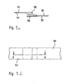
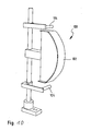
- the closure system to be tested is placed with a loop component and a closure means having mechanical fasteners adhering thereto over a curved surface which is intended to simulate a rounding of the abdominal area of a user (see FIG. 8).
- a flexible substrate for example a single-sided adhesive tape of a preferred width of 25 mm or 50 mm, which is available under the name STA 306 from 3M Kunststoff GmbH located in Neuss, is used .
- the tape is made of polypropylene, its surface is coated by a urethane-modified silicone polymer.
- the basis weight of the pressure-sensitive adhesive is 23 g / m2.
- the mechanical closure components to be used that is to say the material of the loop component 106 forming the outside of the front side parts or of the main part and closure means 108 of the closure system having mechanical closure aids, are conditioned for 24 hours at 23 ° C. and 50% relative humidity.
- the loop component may be a nonwoven or a nonwoven film laminate.
- Test specimens of a size of 50 ⁇ 300 mm are punched out of the loop component and sandwiched in the middle by two adhesive tapes 101 having a width of 50 mm glued together with their adhesive surfaces in such a way that the lower adhesive tape covers the rear side of the planar section and the upper one Adhesive tape, the upper side (in the case of a nonwoven-film laminate, the upper side is the nonwoven side) of the loop component is enclosed by 50 mm in length, resulting in a protrusion of the loop component of 50 x 250 mm (see Figure 9a, Figure 9b)
- the closure means 108 comprising mechanical closure aids is punched over its full length, ie the same length provided in the incontinence diaper - in the case illustrated above 20 mm - and in a width of 25 mm and by two one-sided glued together with their adhesive surfaces
- Adhesive tapes 141 a width of 25 mm fixed so that the o The adhesive tape overfills the rear side of the planar section and the
- the size of the test object with a width of 25 mm and a length dimensioned in this way is selected Section sandwiched midway between the ends of two one-sided above-marked tapes 101 a width of 25 mm such that the lower tape overcases the back of the planar section and the upper adhesive tape the upper side of the loop component in the length so bordered that the Length of the supernatant of the loop component of the length of the portion of the mechanical closure aids having closure means 108 corresponds (see Figure 9c, Figure 9d).
- the thus prepared sections of the closure means 108 comprising the mechanical closure aid and the loop component 106 are laid over one another over the whole area (FIG. 9c, FIG. 9d).
- the evaluation is carried out in such a way that the maximum force ascertained until the release of the closure means is rounded down to two decimal places in N (Newton) and is indicated in the form of an average value of the n measurements.
- hook-and-loop hooks in the form known in the prior art come into question as mechanical closure aids.
- one section having the hook-and-loop hooks is laminated on a respective closure strip material in a manner known per se.
- a respective closure strip is preferably anchored to a free end of the respective side part and in turn has a free user end with the mechanical locking aids.
- each of the closure strips has a lower rigidity and can better adapt to the curve of the body in the wearing state of the diaper.
- the individual sections having the hook-and-loop hooks have a width, that is to say an extension in the transverse direction of the diapers of 1 to 10 mm, especially 2-6 mm.
- the distance between the individual sections is in particular 0.1-3 mm, more particularly 0.7-2 mm.
- closure strip material elastically stretchable at least in regions.
- the mechanical closure aids which are designed as mechanical elements such as preferably Velcro hooks
- adhesive closure aids such as pressure-sensitive adhesive areas on the closure strip to the adhesion for the purpose of primary closure or secondarily for the purpose of disposal of the used diaper even more secure.
- the pressure-sensitive adhesive zones may in particular be provided in an outer region, that is to say the free end of a closure strip, of a respective closure strip.
- closure means having the mechanical closure aids directly on the inside of the side parts.
- the closure means would thus not be arranged on a closure strip which extends beyond the free end of the side part, but within the side edge of the side parts.
- the absorbent incontinence diaper has four discrete, not directly interconnected side parts, such that one side part is attached to both side edges of the front region and one further side part is attached to both side edges of the back region.
- the crotch region of the diaper lying between the front and rear side parts remains free of side sections, which benefits the air circulation of the diaper in the applied state.
- the crotch area of the diaper is formed in this way as it were production waste (without leg cut).
- the incontinence diaper has only two discrete side parts which are not directly interconnected, such that a first side part is attached to the first side edge and a second side part is attached attached to the second page margin.
- first and second side part each extend continuously from the front region over the crotch region into the rear region.
- economic production such as an attractive appearance of the diaper when the side panels are flush with the transverse ends of the main part.
- the side parts preferably have a nonwoven component, in particular the side parts are formed without foils, more particularly the side parts consist of a single or multi-layer nonwoven component.
- the outside of the main part of the incontinence diaper is preferably at least partially, but in particular formed over the entire surface by a nonwoven fabric.
- Nonwovens are considerably cheaper compared to textile loop components and are also known to be extremely kind to the skin. They also give the incontinence diaper a "textile-like" impression.
- the film layer of this nonwoven-film laminate is preferably formed from a single-layer or multi-layer, liquid-impermeable, but preferably nevertheless breathable film.
- the advantage of a breathability of the incontinence diaper is also achieved in the main part.
- thermoplastic polymers As materials for the film are in principle all thermoplastic polymers into consideration. For this a multiplicity of commercial products is available on the market.
- LDPE low density polyethylene
- LLDPE linear low density polyethylene
- MDPE medium density polyethylene
- HDPE high density polyethylene
- various PP polypropylene
- copolymers of ethylene or propylene with each other and with other comonomers are used either in pure form or as polymer blends.
- Usual formulations for hygiene films are z.
- ethylene vinyl acetate EVA
- EAA ethylene acrylate
- EAA ethylene ethyl acrylate
- EAA ethylene acrylic acid
- EMA ethylene methyl acrylate
- EBA polyester
- PA polyamide
- PA polyamide
- Nylon ethylene vinyl alcohols
- PS polystyrene
- PU polyurethane
- olefin thermoplastic elastomers are useful as the thermoplastic polymer materials for the film.
- polyolefins such as e.g. LDPE, LLDPE and PP are preferred. Particular preference is given to mixtures of these polymers, for example mixtures of LDPE and LLDPE, mixtures of LDPE or LLDPE and PP or mixtures of PE or PP of different melting points.
- the film is produced in a conventional manner, for example by blown extrusion or cast method. In these processes during the extrusion introduced into the film strains are as explained in more detail below is at least partially responsible for the fact that the film shows a shrinkage behavior at a later annealing. An additional stretching is not required, but can be done if desired in a conventional manner.
- the provision of the breathability is preferably carried out by mixing in a finely divided filler and stretching the film or the composite. When stretching microcracks in the film, which the required Ensure water vapor and gas permeability, but without significantly affecting the water resistance.
- nonwoven components for the outer side of the main part and as a nonwoven component for the side parts in the front region and preferably also in the back region are suitable.
- Particularly suitable are all nonwovens which contain at least one formulation component based on a thermoplastic polymer.
- the nonwovens may contain fibers of PE, PP, PET, rayon, cellulose, PA and blends of these fibers.
- Bi or multicomponent fibers are also conceivable and advantageous.
- Particularly advantageous are carded nonwovens, spunbonded nonwovens, water jet needled nonwovens, SM nonwovens, SMS nonwovens, SMMS nonwovens or even laminates of one or more of these nonwoven types, wherein S stands for spunbond and M for meltblown nonwoven layers.
- spunbonded nonwovens since they have a high strength in the longitudinal and transverse directions and thus can withstand the shear forces acting on them by the intervention of the mechanical closing aids particularly well.
- the nonwoven fabric component In order to prevent that fibers are torn out of the nonwoven composite when releasing the mechanical fasteners, it is advantageous to provide the nonwoven fabric component with an embossing pattern, by means of which preferably all fibers of the nonwoven component are bonded.
- a thermoprecipitate pattern is advantageous, which is particularly advantageously produced by calendering the nonwoven fabric while supplying thermal energy.
- the embossing pattern may include a plurality of punctiform joints or joining regions in a manner known per se, wherein the joints may assume any conceivable geometric shape.
- the joints may be circular, oval, square, rectangular, diamond-shaped or star-shaped.
- the joining regions of the embossing pattern are arranged such that the joining regions surround non-bonded island-like loop regions.
- the joining areas can surround the loop areas continuously, virtually without gaps. Conceivable and advantageous, however, is the joining areas of a variety of particular To form smaller sections of linear joints, so to provide the joining areas with openings.
- the geometric shape of the unbound island-like loop areas is not critical per se.
- the loop areas may be circular, oval, rectangular, square, triangular, hexagonal, octagonal or other polygonal shapes.
- the joining regions may be formed by a plurality of lines which intersect to form a regular diamond pattern, so that island-like unconnected, diamond-shaped loop regions are surrounded by line-like joining regions.
- the closure means having the mechanical closure aids are securely engageable with these loop areas without the risk of separating fibers from the nonwoven component.
- Such an embossing pattern is for example in EP0882828A1 disclosed.
- the surface portion of the joints or joint areas is preferably 7-40%, in particular 15-30%, more particularly 17-25%.
- the basis weight of the nonwoven fabric component for the outside of the main part is preferably 10-30 g / m 2 , especially 14-25 g / m 2 , more preferably 18-22 g / m 2 .
- the weight per unit area of the nonwoven component for the side parts is preferably 18-60 g / m 2 , in particular 25-45 g / m 2 , more particularly 27-40 g / m 2 and more particularly 28-35 g / m 2 .
- the basis weight of the nonwoven fabric component for the side parts in the front region, and preferably also in the rear region, is greater than the basis weight of the nonwoven component for the outside of the main part. Due to the higher weight per unit area of the nonwoven fabric component for the side parts, a higher closure holding force is possible because the mechanical closure aids can be brought into engagement with more fiber material.
- the higher basis weight of the nonwoven fabric component of the side parts also causes the user to fix the closure means having mechanical fasteners preferably on the side parts and not on the outside of the main part, since the user with a higher basis weight and thus preferably with a higher thickness of the nonwoven component of the side parts higher closure security associated.
- the nonwoven component of the side parts has a higher thickness than the nonwoven component of the outside of the main part, the thickness being determined under a test pressure of 0.5 kPa.
- the nonwoven components of the outside of the main part and the side parts have the same embossing pattern. This is beneficial to the appearance of the hygiene article and to the subjective sense of comfort of the user.
- the nonwoven component of the outside of the side parts in the front region and preferably also in the rear region is preferably formed from a material permeable to aqueous liquids. This promotes the removal of sweat from the inside out.
- the side parts in the front region and preferably also in the rear region substantially consist of a nonwoven component, so that both the outside and the inside of the side parts are essentially formed by the nonwoven component.
- the outer side of a nonwoven foil laminate forming the backsheet of an incontinence diaper according to the invention is intended, with the closure means having the mechanical closure aids, to ensure an over-abdomen holding force which is a secure hold of the diaper on the body ensures.
- the closure means having the mechanical closure aids, to ensure an over-abdomen holding force which is a secure hold of the diaper on the body ensures.
- the lamination of the nonwoven component of the backsheet with the film component of the backsheet can be carried out in a manner known per se by any joining methods, in particular by gluing, embossing, ultrasonic welding or thermal calendering.
- a preferred thermal lamination process is in DE102004042405A1 disclosed. On the DE102004042405A1 is expressly referred to in terms of the thermal laminating method and this method in this respect also explains the disclosure of this description now presented.
- Laminates in which the film has been bonded to the nonwoven layer by direct extrusion are therefore embossed, stretched, in particular by ring rolling known per se, or preferably embossed and stretched.
- the shrinkage of the film forces the nonwoven component associated with it to form a gather, which is also accompanied by an increase in basis weight, so that the nonwoven component subsequently better with the mechanical closure aid having + closure means engageable and higher over-belly holding forces identifies than before tempering.
- the annealing is carried out as hot annealing above the Melting temperature of the films.
- the film preferably has at least one component which has a lower melting point than at least one fiber component of the nonwoven component, so that the fiber structure is not destroyed by the hot-tempering.
- melting point is understood to mean the temperature at which the shear modulus of the material approaches zero with regard to the polymeric materials. As far as polymers with crystalline fractions or crystalline polymers are concerned, the crystalline regions have (also) melted at this temperature.
- the melting point is the temperature at which the film melts in its entirety. If the film does not consist of only one material, it is not important that all components have a melting temperature at or below the melting point, but rather the melting point of the film regularly corresponds to the melting temperature of the main thermoplastic component.
- a breathable film containing 60% calcium carbonate, 32% of a polymer having a crystalline melting temperature of 138 ° C and 8% of a polymer having a crystalline melting temperature of 158 ° C has a melting point of about 138 ° C.
- the breathability is e.g. predominantly achieved by the addition of a finely divided filler such as calcium carbonate, the very high melting temperature but not significantly affects the melting point of the film at additions even over 50 wt .-%.
- a film of a mixture of 60% calcium carbonate with 40% polymer has the same crystallite melting point as the polymer.
- the preferred hot tempering of the nonwoven film laminate can be done either directly following its manufacture (in-line) or independently at a later time (off-line).
- the hot annealing takes place in a manner known per se for tempering, but the temperature is to be set at least above the melting temperature of the main thermoplastic component of the film of the nonwoven-film laminate.
- the heating process window is given at the minimum temperature by the molten state of the film which is absolutely necessary in the case of hot tempering.
- the heating is limited by the crystallite melting point of the nonwoven web, and in the case of breathable films optionally additionally by a loss of the breathability of the film occurring at too high temperatures.
- the heat treatment should be carried out at such temperatures that the melt is still too viscous to close the pores.
- the breathability may also be generated only after hot tempering, by subjecting the composite to e.g. is still subjected to a ring-rolling.
- the heat treatment is preferably carried out by heating the nonwoven foil laminate by means of one or more heat rollers or alternatively, for example by means of IR radiation, so that the film, ie at least the low-melting raw material component of the film, reaches the molten state.
- the composite runs directly on slower running cooling rollers, so that a shock-like cooling occurs and by the 1 - 10% lower peripheral speed, a shrinkage between the heating element and cooling is possible.
- the shrinkage should be in the range of 1-10% (length / length) in the machine direction, transverse to this, depending on the preparation and pretreatment of the film is also a shrinkage. For blown film, the transverse shrinkage is typically also at 1 to 10%, in cast films it is typically lower.
- the temperature of the cooling rolls is preferably 10-30 ° C, so that the cooling of the composite on below the melting temperature of the film is very fast, eg within fractions of a second.
- breathability of the side parts in the front region and preferably also in the back region is greater than the breathability of the backsheet.
- the side parts in the front and / or back are folded at least by a longitudinally extending fold line on itself.
- sections of the side parts which are folded onto one another and are in planar contact with one another in this folded configuration are detachably fixed to one another at joints or joint areas.
- This releasable fixation is preferably formed by thermally or ultrasonically generated, preferably punctiform joints.
- a grip region for unfolding the material section is provided in a part section of a respective side part that forms the free end of the side part in the transverse direction.
- this grip region can be formed by a longitudinal side edge section of the mentioned subsection, which can be grasped with the fingers of a user. It would also be conceivable that a separate manually engageable gripping element is provided at the relevant section, but this would mean an additional manufacturing effort.
- the side parts in the front region and preferably also in the rear region are folded onto themselves by at least two fold lines, so that a configuration which is z-shaped in section is produced.
- the side parts are folded by three fold lines on itself.
- the extension of a side part attached to the main part in the deployed state in the transverse direction beyond the side edge of the main part is preferably at least 10 cm, in particular at least 15 cm, and more particularly at least 18 cm. It is preferably at most 35 cm, in particular at most 30 cm and more particularly at most 27 cm.
- the attached to the main part side parts have in the region of the attachment to the main part an extension in the longitudinal direction of the incontinence diaper of preferably at least 10 cm, in particular at least 14 cm, in particular at least 18 cm and more particularly at least 22 cm.
- the side parts at least in the rear region on a reinforcing means, which is viewed narrower than a respective lateral part and which is at least provided in a side edge of the main part bridging area, ie both a side edge region of the main part and a part of the Part of the side overhanging in the transverse direction.
- the tear strength of the side parts was increased considerably.
- the reinforcing means is substantially at least almost to a step region facing the transverse edge of the side part extends, so if it is preferably flush with the edge of the side edge or even encloses or encloses the transverse edge.
- the reinforcing means could be extended in the longitudinal direction of the hygiene article, for example over the entire longitudinal extent of the attached side part. However, it has been found that this is not absolutely necessary, but that it proves to be also advantageous if the reinforcing means in the longitudinal direction of the sanitary article has a smaller dimension than the attached side part itself as a result of the force occurring in use on the side part and on the attachment region of side part and diaper main part, it is quite sufficient if the reinforcing agent extends, for example, only up to 80% or in particular to 60% and more particularly to 50% of the longitudinal extent of the side part. As a result, compared to the continuous longitudinal reinforcement material savings can be achieved.
- the reinforcing means always extends in the transverse direction beyond the side edge of the main part in the direction of the free end of the side part.
- This extension of the region of the reinforcing means, which extends beyond the side edge of the main part, in the direction of the free end of the side part, measured from the side edge of the main part, is preferably at most 50%, in particular at most 35%, more particularly at most 25%, further in particular at most 20% in particular at most 15%, more particularly at most 10% of the transverse extent of the side part.
- the reinforcing means also extends transversely in the direction of the longitudinal centerline of the body so as to at least partially overhang the overlap region of the side member and the materials of the body. Preferably, the reinforcing means completely overlaps the overlapping area.
- a respective attached side part can be rectangular in shape, without the aforementioned tear problem would oppose that.
- the reinforcing means provided according to the invention may advantageously be formed by an attached reinforcing section, that is to say by an additional material added to the respective side section, in particular applied to the respective side section.
- This reinforcing portion may be formed, for example, strip-shaped. This reinforcing portion may further take any form.
- This reinforcing section may for example also be in the form of a triangle.
- the reinforcing section may be formed by a nonwoven material, a textile material or a film. Like the side parts, it can be fed in and added in an endless manufacturing process using the cut & place process.
- the outside of the nonwoven fabric is preferably engageable with the closure means having mechanical closure aids, such as for the disposal of the used diaper.
- the reinforcing portion has the same embossing pattern as the nonwoven fabric component of the side part and / or the outside of the main part.
- the reinforcing means may be attached to one or both tops of the side panel.
- the reinforcing means is formed by the material of the respective side part itself, in that the side part is folded once or several times in the region bridging the side edge of the main part.
- the side edge of the main part overlapping or overlapping region of the respective side part by a material doubling or multiplication by folding the side part.
- a particularly effective tear protection can be created.
- Particularly advantageous is a considered in the longitudinal direction of the hygiene article Z-shaped folding of the respective side part.
- FIG. 1 schematically shows a plan view of the outside of an absorbent incontinence diaper 2 in the folded-out state.
- the incontinence diaper comprises a main part 4 with a longitudinal center line L consisting of a front region 6, a back region 8 and a crotch region 12 located in the longitudinal direction L.
- an absorbent body 14 which is usually between chassis-forming materials of the main part, ie in particular between a liquid-permeable topsheet 11 and a substantially liquid-impermeable backsheet 10 of the main part 4 is arranged.
- the absorbent body can be applied as a separate unit provided with leakage protection to a chassis-forming layer of the main part and can be fixed detachably or non-detachably there.
- the incontinence diaper 2 furthermore comprises front side parts 16 and rear side parts 17, which are attached to the main part 4 as separate nonwoven components on both sides. They each have a rectangular shape, which is not mandatory, but advantageous in terms of avoiding cutting waste.
- the side parts are in a hatched area shown overlapping area 18 with chassis forming Materials of the main part 4, so for example, inextricably linked to the backsheet 10 and / or the topsheet 11 for proper use. They extend beyond lateral longitudinal edges 5 of the main part 4 in the transverse direction Q of the main part 4 addition.
- the side panels 16, 17 are intended and intended to be joined together in the applied state of the incontinence diaper to form a circumferentially continuous waist region of the sanitary article.
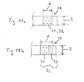
- FIG. 11 a shows an enlarged plan view of the user end of one of the closure strips 30 with a closure means 32, which is formed solely by the section of mechanical closure aids 31 in the form of hook-and-loop hooks.
- the width B of the section of mechanical shuttering aids 31 in the present case is 25 mm and its length A in the present case is 20 mm.
- 11 b shows an alternative embodiment of the user end of a closure strip 30 with a closure means 32 which is formed from a section of mechanical closure aids 31 and a section of adhesive closure means in the form of a pressure-sensitive adhesive area 33, the width B of the closure means 32 being 25 mm and the length A of the closure means 32 is 30mm.
- At least the front side parts 16, preferably also the rear side parts 17, are made of a nonwoven component, in the case shown formed of a PP spunbonded fabric of 30 g / m 2 .
- the fiber thickness is 2 dtex.
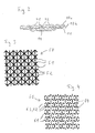
- the outside of the spunbonded fabric has an embossing pattern 20, which is indicated only schematically in FIG.
- the joining areas formed by hot-calendering are formed by a plurality of lines, namely two groups of lines parallel to each other within a group, the lines of which intersect with those of the other group to form a regular diamond pattern at an angle of 33 °, so that island-like unconnected, diamond-shaped loop areas 21 are surrounded by line-like joining areas 22.
- the joining regions 22 forming lines in the illustrated case have a width of 1.0 mm and an embossing depth of 0.6 mm.
- the distance between two adjacent parallel lines of both groups of lines is 4.7 mm.
- the embossing area that is to say the sum of the area of all joining areas 22 relative to the total area of the embossing pattern (joining areas + loop areas) is 32%.
- closure means 32 arranged on the inside of the closure strips 30 of the rear side parts 17 are securely engageable with these loop regions 21 without the risk of excessively removing fibers from the nonwoven fabric component.
- the outside of the backsheet 10 of the main part 4 is formed by a backsheet nonwoven fabric component 10a.
- the backsheet is formed from a nonwoven foil laminate, that is, between the absorbent body 14 and the backsheet nonwoven fabric component 10a, a backsheet film component 10b is arranged.
- the joining regions 42 and the loop regions 41 of the embossing pattern 40 are also shown schematically in FIG.
- the backsheet nonwoven fabric component 10a is formed in the illustrated case of a PP spunbond, but of 20 g / m 2 .
- the fiber thickness is 2 dtex.
- the outside of this spunbonded fabric has an embossing pattern 40 (shown only schematically in FIG. 1).
- the embossing pattern 40 extends over the entire outer side of the main part 4 from the front 6 over the step 12 to the back region 8 of the incontinence diaper 2.
- the joining areas produced by hot calendering are formed by a plurality of lines that form a regular diamond pattern cut, so that island-like arranged unconnected diamond-shaped loop areas 41 are surrounded by line-like joining areas 42.
- the embossing pattern 40 of the backsheet nonwoven fabric component 10a is identical to that of the embossing pattern 20 of the nonwoven component of the front side members 16.
- the over-tummy holding forces between the closure means 32 and the outside of the side members 16 are preferably at least 58 N / 25mm, and are higher than the over-tummy holding forces between the closure means 32 and the outside of the backsheet nonwoven component, which are preferably nonetheless at least 20 N / 25mm. In essence, this is ensured by the higher basis weight of the nonwoven component of the side panels.
- FIG. 3 shows schematically an alternative hot-dip induced embossing pattern 50 for the nonwoven components of the front side panels 16 and / or the backsheet 10.
- the embossing pattern 50 has joining areas formed by a plurality of lines and intersecting to form a regular pattern. so that island-like unconnected, triangular loop areas 51 are surrounded by line-like joining areas 52.
- the embossing area that is to say the sum of the area of all joining areas 52 relative to the total area of the region of the nonwoven fabric covered by the embossing pattern 50, is in this case 23%.
- FIG. 4 shows schematically and not to scale a modification of the embossing pattern 50 shown in FIG. 3.
- the embossing pattern is an open embossing pattern 60.
- the joining regions 62 do not continuously surround the triangular loop regions 61, ie the joining regions 62 are not continuous Variety of particular smaller sections of linear joints 63 formed, which have no intersections with each other; the joining regions 62 are thus provided with apertures 64.
- the line-shaped joints 63 each form the non-hitting legs of a triangle.
- the line-shaped joints 63 have a length of 3-7 mm, in particular 4-5 mm.
- the joints 63 have a uniform length so as to form a plurality of equilateral triangles.
- the width of the joints 63 is preferably 0.2-0.8 mm, in particular 0.4-0.6 mm.
- the embossing depth is preferably 0.2-1.0 mm, in particular 0.4-0.8 mm.
- the embossing surface that is to say the sum of the area of all joint regions 62 relative to the total area of the region covered by the embossing pattern 60, is preferably 15-50%, in particular 17-40%, more particularly 19-25%. In the case illustrated in FIG. 4, the embossing area is approximately 21%.
- FIG. 5 shows a detail of the rear portion of an inventive design of the incontinence diaper 2, wherein the schematically illustrated rear side member 17 has a reinforcing means 7, which is narrower in the transverse direction Q than the side part 17.
- the reinforcing means 7 extends in the transverse direction Q on the side edge 5 of Body 4 out.
- the reinforcing means 7 thereby partially overlaps the overlapping area 18, as shown schematically in FIG. It therefore extends both over the lateral side edge 5 in the direction of the free end 27 of the side part 17 and in the direction of the overlapping region 18, that is to say in the direction of a longitudinal center line L of the main part 4.
- the reinforcing means 7 may be formed in various ways, as long as it causes a tear protection of the side portion 17, in particular at initiation of an obliquely directed to the transverse direction Q tensile force on the side part 17 and the overlap region 18 when closing the diaper by means of the closure strip not shown in Figure 5 30.
- the reinforcing means 7 may be formed, for example, by an additional reinforcing section, for example of fleece or foil, or of any reinforcing material per se. This can be applied to the material of the side section 17 by any joining methods, in particular using an adhesive.
- the reinforcing means 7 is formed by the material of the side part 17 itself, by the side part 17 is folded on itself, in particular z-shaped, with the folded configuration in the transverse direction Q on the side edge 5 of the main part. 4 extends in the direction of the free end of the side part 17 also.
- a particularly preferred incontinence diaper 2 has the following components which are relevant with regard to the over-abdomen holding forces:
- front side parts 16 As front side parts 16:
- Material X consisting of 30 g / m 2 polypropylene spunbonded web, fiber thickness 2 dtex Hot calender embossing pattern on the outside of the side panel material of Figure 4, wherein the joints 63 have a uniform length of 4.5 mm with a width of the joints of 0.4 mm and an embossing depth of 0.65 mm and an embossing area of 21.13 %.
- the material is available from Fa. Corovin GmbH, Wohltorfer Str. 124, D-31201 Peine.
- backsheet 10 As backsheet 10:
- Material Y A nonwoven-film laminate was used, which preferably forms the complete outside of the main part 4 of the incontinence diaper 2.
- the nonwoven component consists of a 20 g / m 2 polypropylene spun fleece, fiber thickness 2 dtex with a H hinderkalanderlessnessgemuster as that of the front side parts 16, ie a H hinderkalanderlessnessgemuster according to Figure 4, wherein the joints 63 have a uniform length of 4.5 mm with a width of the joints of 0.4 mm and with an embossing depth of 0.65 mm and an embossing area of 21.13%, available from Corovin GmbH, Wohltorfer Str. 124, D-31201 Peine.
- the film component is a bubble-extruded film available from Rheinische Kunststoffwerke GmbH, Alkorstrasse 6, D-83512 Wasserburg.
- the formula of the film consists of 70% low-melting polypropylene compound (melting point approx. 137 - 143 ° C) and 30% high-melting polypropylene compound (melting point 158 - 164 ° C).
- the compounds each consist of a blend of polymer raw material plus 60% CaCO 3 (chalk). After the blown extrusion of the so-called precursor film with a basis weight of 40 g / m 2 , the film was stretched over a monoaxial MDO stretching machine in the machine direction.
- the film web was stretched with a degree of stretching of 1: 2 in the machine direction, ie to a basis weight of 20 g / m 2 , and thus generated the breathability.
- the breathable film was then washed together with the polypropylene spunbond (20 g / m 2 ) in a device as shown in FIG DE102004042405A1 is disclosed and described thermolaminiert at 130 to 140 ° C.
- the produced nonwoven sheet laminate was subjected to ring rolling in CD (cross machine direction). This laminate was then fed to the hot annealing.
- the laminate ran over two heating rollers arranged one behind the other, wherein it reached a temperature above the melting temperature of the film, but was heated below the melting temperature of the polypropylene spunbonded nonwoven, namely 130-140 ° C.
- the laminate was passed directly over two consecutively arranged chill rolls. These had a much lower circulation speed than the heating rollers, as the desired shrinkage in the machine direction, in this case about 5%.
- Material Z Velcro hook section with the dimensions 20 x 25 mm.
- the representation of the shape of these Velcro hooks can be seen in Figures 6 and 7.
- the hooks have a mushroom-shaped figure ( Figure 6) with a hexagonal surface of the head 8 ( Figure 7).
- the hook density (number of hooks per surface) is 288 hooks per cm 2 .
- the material is made of polypropylene and has a thickness of 0.42 mm. It is made by extrusion.
- the height of the mushroom-shaped elevations opposite the bottom of the material is 0.26 mm.
- the distance between the edges of the hook heads is 200 ⁇ m.
- the over-belly holding forces of the closure means with the outside of the side panel material are thus higher than the over-belly holding forces of the closure means with the outside of the backsheet-forming nonwoven foil laminate.
Abstract
Description
Die vorliegende Erfindung betrifft eine absorbierende Inkontinenzwindel mit einem Rückbereich, einem Vorderbereich und einem dazwischen liegenden Schrittbereich und mit erstem und zweitem Seitenrand, und mit einem Hauptteil mit einer in Gebrauch dem Körper zugewandten Innenseite und einer in Gebrauch dem Körper abgewandten Außenseite, wobei der Hauptteil einen Saugkörper und ein Backsheet auf der dem Körper abgewandten Seite des Saugkörpers umfasst, und wobei der Saugkörper eine geringere Breite aufweist als das Backsheet, und mit an den ersten und zweiten Seitenrand angefügten diskreten Seitenteilen. Die Inkontinenzwindel ist für Erwachsene vorgesehen und ist als Wegwerfwindel ausgebildet, das heißt zum einmaligen Gebrauch bestimmt.The present invention relates to an absorbent incontinence diaper having a back region, a front region and an intermediate crotch region and first and second side edges, and a main part having an inner side facing the body in use and an outer side facing away from the body in use, the main part having a Absorbent body and a backsheet on the side facing away from the body of the absorbent body, and wherein the absorbent body has a smaller width than the backsheet, and attached to the first and second side edge discrete side parts. The incontinence diaper is intended for adults and is designed as a disposable diaper, that is intended for single use.
Derartige Inkontinenzwindeln sind beispielsweise auch aus der
Bei derartigen Inkontinenzwindeln können die erwähnten Seitenteile aus einem anderen Material gebildet sein als der Hauptteil. Beispielsweise können die Seitenteile, die häufig auch als "Ohren" der Inkontinenzwindel bezeichnet werden, atmungsaktiv, insbesondere luft- und wasserdampfdurchlässig ausgebildet werden, wohingegen der Hauptteil, der häufig auch als Chassis bezeichnet wird, flüssigkeitsundurchlässig, insbesondere feuchtigkeitsundurchlässig ausgeführt sein kann. Zum Schließen der Inkontinenzwindel werden die vorzugsweise unlösbar am Rückbereich angefügten Seitenteile auf die Bauchseite des Benutzers geschlagen und dort entweder mit der Außenseite des Vorderbereichs des Hauptteils oder mit der Außenseite der Seitenteile des Vorderbereichs lösbar verbunden.In such incontinence diapers, the mentioned side parts may be formed of a different material than the main part. For example, the side panels, which are often referred to as the "ears" of the incontinence diaper, breathable, in particular air and water vapor permeable formed, whereas the main part, which is often referred to as a chassis, liquid impermeable, in particular moisture impermeable can be performed. To close the incontinence diaper, the preferably non-detachably attached to the rear portion side parts are beaten on the abdominal side of the user and there detachably connected either to the outside of the front region of the main body or with the outside of the side parts of the front area.
Insoweit eine derartige Inkontinenzwindel mit mechanischen Verschlusshilfen ausgestattet wird, resultiert das Problem, dass für die üblicherweise an den hinteren Seitenteilen angeordneten meist als Kletthaken ausgeführten Verschlusshilfen ein entsprechender Landebereich an der Außenseite des Vorderbereiches der Windel vorgesehen sein muss, der mit den Kletthaken in Eingriff bringbar sein muss.Insofar as such an incontinence diaper is equipped with mechanical closure aids, the problem arises that for the usually arranged on the rear side panels usually designed as Velcro closure aids a corresponding landing area must be provided on the outside of the front portion of the diaper, which can be brought into engagement with the Velcro hooks got to.
Üblicherweise wird die Außenseite des Hauptteils derartiger Inkontinenzwindeln allerdings durch ein Folienmaterial gebildet, um ein Austreten von Flüssigkeit durch den Saugkörper hindurch nach außen zu verhindern. Die Seitenteile derartiger Inkontinenzwindeln sind vorzugsweise aus glatten Vliesmaterialien gebildet, um dort, wo keine sichere Flüssigkeitsbarriere erforderlich ist, die Hautfreundlichkeit der Windel zu verbessern. Somit würde eine Landefläche zum sicheren Festlegen der Kletthaken auf der Außenseite des Vorderbereichs der Windel das Anbringen eines zusätzlichen Materials, insbesondere eine an sich bekannte textile Loop-Komponente erfordern. Derartige Loop-Komponenten müssten sich allerdings über weite Teile des Vorderbereiches der Außenseite der Windel erstrecken, um das bei Inkontinenzwindeln (Windeln für Erwachsene) erforderliche hohe Maß an Flexibilität in der Größenanpassung zu gewährleisten. Da textile Loop-Komponenten einen wesentlichen Kostenfaktor bilden, verbietet sich eine derartige Lösung schon aus wirtschaftlichen Gründen.Usually, however, the outside of the main part of such incontinence diapers is formed by a sheet material to prevent leakage of liquid through the absorbent body to the outside. The side panels of such incontinence diapers are preferably formed of smooth nonwoven materials to improve the skin-friendliness of the diaper where no secure fluid barrier is required. Thus, a landing surface would require the attachment of an additional material, in particular a known per se textile loop component for securely fixing the Velcro hooks on the outside of the front portion of the diaper. However, such loop components would need to extend over much of the front portion of the outside of the diaper to ensure the high degree of flexibility in sizing required for incontinence diapers (adult diapers). Since textile loop components constitute a significant cost factor, such a solution prohibits for economic reasons.
Des Weiteren hat sich bei Inkontinenzwindeln der bekannten Art gezeigt, dass das subjektive Empfinden des Komforts der Windel trotz der hautfreundlichen und luftwie wasserdampfdurchlässigen Seitenteile deutliche Unterschiede ausweist.Furthermore, it has been shown in incontinence diapers of the known type that the subjective sense of comfort of the diaper despite the skin-friendly and luftwie water vapor permeable side panels shows significant differences.
Zur Lösung dieser Probleme wird vorgeschlagen, dass die mechanische Verschlusshilfen aufweisenden Verschlussmittel zum bestimmungsgemäßen Festlegen der Windel an den Körper eines Menschen zumindest bereichsweise sowohl direkt an der Außenseite des Hauptteils als auch direkt an der Außenseite der Seitenteile im Vorderbereich lösbar festlegbar sind, wobei die Haltekräfte zwischen den Verschlussmitteln und der Außenseite des Hauptteils geringer sind als die Haltekräfte zwischen den Verschlussmitteln und der Außenseite der Seitenteile im Vorderbereich der Windel. Vorzugsweise werden die Haltekräfte als Über-Bauch-Haltekräfte ermittelt.To solve these problems, it is proposed that the closure means having mechanical closure aids for the intended setting of the diaper to the body of a human are at least partially releasably secured both directly on the outside of the body and directly on the outside of the side parts in the front region, the holding forces between the closing means and the outside of the main part are smaller than the holding forces between the closing means and the outside of the side parts in the front area of the diaper. Preferably, the holding forces are determined as over-abdominal holding forces.
Die die Außenseite des Hauptteils und die die Außenseite der Seitenteile im Vorderbereich bildenden Materialien sind also erfindungsgemäß so gewählt, dass sie neben ihren jeweiligen Primärfunktionen auch als Landefläche für die mit mechanischen Verschlusshilfen versehenen Verschlussmittel dienen können. Überraschenderweise hat sich außerdem gezeigt, dass dann, wenn die Haltekräfte zwischen den Verschlussmitteln und der Außenseite des Hauptteils geringer sind als die Haltekräfte zwischen den Verschlussmitteln und der Außenseite der Seitenteile im Vorderbereich der Windel die Nutzer der Windel dazu tendieren, die Windel so zu schließen, dass die Verschlussmittel an der Außenseite der Seitenteile im Vorderbereich der Windel festgelegt werden. Dies wiederum erhöht den Tragekomfort, da hiermit ein Überlappen der Seitenteile mit dem Backsheet vermieden wird, wodurch erst das Wirksamwerden der Vorteile der Luft- und Wasserdampfdurchlässigkeit der Seitenteile ungehindert möglich wird. Außerdem ist die Gefahr des Beschädigens des Backsheets des Hauptteils und damit die Gefahr des Durchschlagens von Flüssigkeit durch die mechanischen Verschlusshilfen reduziert.The outer side of the main part and the outer side of the side parts in the front region forming materials are thus selected according to the invention so that they can serve in addition to their respective primary functions as a landing area for provided with mechanical closure means closure means. Surprisingly, it has also been found that when the holding forces between the closure means and the outside of the body are less than the holding forces between the closure means and the outside of the side panels in the front of the diaper, the users of the diaper tend to close the diaper so that the closure means are fixed on the outside of the side parts in the front region of the diaper. This in turn increases the wearing comfort, since this overlap of the side panels is avoided with the backsheet, whereby only the effect of the advantages of the air and water vapor permeability of the side parts is unhindered possible. In addition, the risk of damaging the backsheet of the main part and thus the risk of liquid leakage through the mechanical locking aids is reduced.
Wesentlich ist, dass auch die Haltekräfte zwischen der Außenseite des Hauptteils und den mechanische Verschlusshilfen aufweisenden Verschlussmitteln einen Halt der Windel am Körper gewähren. Hierzu hat es sich als vorteilhaft erwiesen, wenn die Über-Bauch-Haltekräfte zwischen den Verschlussmitteln und der Außenseite des Hauptteils 57-20 N/25mm, insbesondere 50-25 N/25mm betragen.It is essential that the holding forces between the outside of the main part and the closure means having mechanical closure aids also ensure a hold of the diaper on the body. For this purpose, it has proved to be advantageous if the over-belly holding forces between the closure means and the outside of the main part 57-20 N / 25mm, in particular 50-25 N / 25mm amount.
Des Weiteren betragen die Über-Bauch-Haltekräfte zwischen den Verschlussmitteln und der Außenseite der Seitenteile im Vorderbereich vorzugsweise 90-58 N/mm, insbesondere 80-60 N/25mm.Furthermore, the over-belly holding forces between the closure means and the outside of the side parts in the front region are preferably 90-58 N / mm, in particular 80-60 N / 25 mm.
Zur Bestimmung der Über-Bauch-Haltekräfte werden die Verschlusskräfte bei Scherbeanspruchung gemessen. Nachfolgend wird eine Prüfmethode für die Ermittlung der Verschlusskräfte bei Scherbeanspruchung angegeben:To determine the over-belly holding forces, the closure forces are measured under shear stress. The following is a test method for determining shear forces under shear:
Für die Durchführung der Prüfmethode kann ein Zugprüfgerät Typ Z010 / TN 2S, Messdose 100 N, erhältlich bei der Firma Zwick GmbH & Co KG, Ulm, Deutschland, mit einer Klemmbackenbreite zum Einspannen des Prüflings von 60 mm verwendet werden. Bei der Durchführung der Prüfmethode wird das zu prüfende Verschlusssystem mit einer Schlaufen-Komponente und einem darauf haftenden mechanische Verschlusshilfen aufweisenden Verschlussmittel über eine gekrümmte Fläche gelegt, welche eine Rundung des Bauchbereichs eines Benutzers simulieren soll (siehe Figur 8). Zur Verbindung der Verschlusskomponenten mit den Klemmbacken des Zugprüfgeräts wird ein biegsames Substrat, beispielsweise ein einseitig klebendes Klebeband einer bevorzugten Breite von 25 mm, bzw. 50 mm, das unter der Bezeichnung STA 306 bei der Firma 3M Deutschland GmbH ansässig in Neuss erhältlich ist, verwendet. Das Klebeband ist aus Polypropylen, seine Oberfläche ist beschichtet durch ein urethanmodifiziertes Siliconpolymer. Das Flächengewicht des Haftklebstoffauftrags beträgt 23 g/m2. Der über die gekrümmte Fläche gelegte Prüfling, bestehend aus aufeinander haftenden flächenhaften Abschnitten des Verschlusssystems, wird durch Verwendung des Zugprüfgeräts auf Zug beansprucht, woraus sich eine scherende Beanspruchung der aneinander haftenden flächenhaften Abschnitte ergibt.To carry out the test method, a tensile tester type Z010 / TN 2S, load cell 100 N, available from Zwick GmbH & Co KG, Ulm, Germany, with a jaw width for clamping the test piece of 60 mm can be used. When carrying out the test method, the closure system to be tested is placed with a loop component and a closure means having mechanical fasteners adhering thereto over a curved surface which is intended to simulate a rounding of the abdominal area of a user (see FIG. 8). To connect the closure components with the clamping jaws of the tensile tester, a flexible substrate, for example a single-sided adhesive tape of a preferred width of 25 mm or 50 mm, which is available under the name STA 306 from 3M Deutschland GmbH located in Neuss, is used , The tape is made of polypropylene, its surface is coated by a urethane-modified silicone polymer. The basis weight of the pressure-sensitive adhesive is 23 g / m2. The specimen placed over the curved surface, consisting of adhering planar sections of the closure system, is subjected to tensile stress by use of the tensile tester, resulting in a shearing stress on the adhering planar sections.
Die zu verwendenden mechanischen Verschlusskomponenten, also das Material der die Außenseite der vorderen Seitenteile oder des Hauptteils bildenden Schlaufen-Komponente 106 und ein mechanische Verschlusshilfen aufweisendes Verschlussmittel 108 des Verschlusssystems, werden über 24 h bei 23° C und 50 % relativer Luftfeuchte konditioniert. Wie unten noch näher beschrieben werden wird, kann es sich bei der Schlaufen-Komponente beispielsweise um einen Vliesstoff oder ein Vliesfolienlaminat handeln. Es werden Prüflinge einer Größe von 50 x 300 mm aus der Schlaufen-Komponente ausgestanzt und sandwichartig mittig durch zwei mit ihren Klebeflächen gegeneinander geklebte einseitige Klebebänder 101 einer Breite von 50 mm derart fixiert, dass das untere Klebeband die Rückseite des flächenhaften Abschnittes überfängt und das obere Klebeband die obere Seite (bei einem Vliesfolienlaminat ist die obere Seite die Vliesseite) der Schlaufen-Komponente in der Länge um 50 mm einfasst, so dass ein Überstand der Schlaufen-Komponente von 50 × 250 mm resultiert (siehe Figur 9a, Figur 9b) Desgleichen wird das mechanische Verschlusshilfen aufweisende Verschlussmittel 108 über seine volle Länge, das heißt der gleichen Länge, die bei der Inkontinenzwindel vorgesehen wird - im dargestellten Fall über 20 mm -, und in einer Breite von 25 mm ausgestanzt und durch zwei mit ihren Klebeflächen gegeneinander geklebte einseitige Klebebänder 141 einer Breite von 25 mm derart fixiert, dass das obere Klebeband die Rückseite des flächenhaften Abschnittes überfängt und das untere Klebeband bündig an den flächenhaften Abschnitt angrenzt (siehe Figur 9a und Figur 9b). Der flächenhafte Abschnitt der mechanische Verschlusshilfen aufweisenden Verschlussmittel 108 wird nun auf die Schlaufen-Komponente 106 aufgelegt, wobei der Abstand von der Längsendkante der Schlaufen-Komponente 10 mm und von den seitlichen Längsrändern je 12,5 mm betragen soll (s. Figur 9a). Wenn die zur Verfügung stehende Schlaufen-Komponente 106 von vornherein eine kleinere Abmessung aufweist, so dass keine Bereitstellung eines 50 mm x 300 mm großen Prüfling möglich ist, wird die Größe des Prüflings mit einer Breite von 25 mm und einer derart bemessenen Länge gewählt und dieser Abschnitt sandwichartig mittig zwischen die Enden zweier einseitiger oben näher gekennzeichneter Klebebänder 101 einer Breite von 25 mm derart fixiert, dass das untere Klebeband die Rückseite des flächenhaften Abschnittes überfängt und das obere Klebeband die obere Seite der Schlaufen-Komponente in der Länge derart einfasst, dass die Länge des Überstandes der Schlaufen-Komponente der Länge des Abschnittes des mechanischen Verschlusshilfen aufweisenden Verschlussmittels 108 entspricht (siehe Figur 9c, Figur 9d). Solchenfalls werden die so vorbereiteten Abschnitte des mechanische Verschlusshilfen aufweisenden Verschlussmittels 108 und der Schlaufen-Komponente 106 vollflächig übereinander gelegt (Figur 9c, Figur 9d).The mechanical closure components to be used, that is to say the material of the
Sollte kein 25 mm breiter Abschnitt des mechanische Verschlusshilfen aufweisenden Verschlussmittels 108 zur Verfügung stehen, wird ein entsprechend schmalerer Abschnitt verwendet. Solchenfalls werden die ermittelten Kraftwerte rechnerisch auf einen 25 mm breiten Abschnitt normiert, derart dass die gemessenen Kräfte mit einem Faktor f multipliziert werden, welcher sich ergibt aus 
Die so oder auf die zuvor beschriebene Art aufeinander gelegten flächenhaften Abschnitte werden durch viermaliges Anrollen mit einer 50 mm breiten und im Durchmesser 100 mm starken Rolle mit glatter Oberfläche und einem Rollengewicht von 5 kg miteinander verbunden, wobei die Anrollgeschwindigkeit 20-100 mm/sec beträgt.The sheet-like portions superimposed on each other in the above-described manner are joined by rolling four times with a 50 mm-wide and 100 mm-thick smooth-surfaced roll having a roll weight of 5 kg, and the winding speed is 20-100 mm / sec ,
Die wie vorstehend beschrieben verlängerte Schlaufen-Komponente 106 wird in die untere Klemmbacke 122 des Zugprüfgeräts mittig zentriert eingespannt, und das gegenüberliegende Ende des wie vorstehend beschrieben verlängerten mechanische Verschlusshilfen aufweisenden Verschlussmittels 108 wird in die bewegliche obere Klemmbacke 123 des Zugprüfgeräts ebenfalls zentriert eingespannt. Der so eingespannte Prüfling wird über die aus Figur 8, Figur 10 ersichtliche Vorrichtung 100, welche den Bauch- oder Hüftbereich eines Benutzers simulieren soll, gelegt. Diese Vorrichtung 100 ist in Figur 10 perspektivisch dargestellt. Man erkennt eine bogenförmig gekrümmte Fläche 102 aus poliertem Stahl mit einer Rautiefe von 5 bis 25 mm und mit einem Krümmungsradius R von zumindest abschnittsweise 400 mm und einer Sehnenlänge SL von 300 mm. Des Weiteren sind oberhalb und unterhalb der gekrümmten Fläche 102 Umlenkrollen 104 mit einem Durchmesser von 18 mm vorgesehen, welche den über die gekrümmte Fläche gelegten Prüfling in die vertikale Richtung um H = 88 mm umlenken, wo er dann mit Klemmen 120, 124 des nicht dargestellten Zugprüfgeräts verbunden wird. Die Umlenkung erfolgt um einen Winkel α von 60°. Hierdurch wird der Abzugswinkel im Wesentlichen tangential zu der gekrümmten Fläche und konstant gehalten. Die aufeinander gelegten flächenhaften Abschnitte 106, 108 der Komponenten des Verschlussmittels werden in Bezug auf die gekrümmte Fläche 102 so positioniert, dass das mechanische Verschlusshilfen aufweisende Verschlussmittel mittig zentriert im Scheitelpunkt 5 der gekrümmten Fläche 102 zu liegen kommt. Es wird dann die bewegliche Klemmbacke 124, mit der das mechanische Verschlusshilfen aufweisende Verschlussmittel verbunden ist, mit der nachfolgend angegebenen Prüfgeschwindigkeit in Pfeilrichtung P bewegt, und es wird währenddessen die dabei auftretende Zugkraft zwischen den Klemmen ermittelt. Die Prüfparameter sind:
- Prüfgeschwindigkeit: 300 mm/min
- Einspannlänge des Prüflings: 430 mm (s. Figur 8)
- Messweg: Strecke bis zur Ablösung der Verschlussmittelkomponenten voneinander
- Vorkraft: 0,2 N
- Prüfanzahl: n ≥ 6.
- Test speed: 300 mm / min
- Clamping length of the specimen: 430 mm (see Figure 8)
- Measuring path: Distance to the separation of the closing agent components from each other
- Pre-load: 0.2 N
- Test number: n ≥ 6.
Die Auswertung erfolgt dergestalt, dass die bis zum voneinander Ablösen der Verschlussmittel ermittelte Maximalkraft gerundet auf zwei Dezimalstellen in N (Newton) notiert wird und in Form eines Mittelwerts der n-Messungen angegeben wird.The evaluation is carried out in such a way that the maximum force ascertained until the release of the closure means is rounded down to two decimal places in N (Newton) and is indicated in the form of an average value of the n measurements.
Als mechanische Verschlusshilfen kommen insbesondere Kletthaken in der im Stand der Technik bekannten Form in Frage. Vorzugsweise ist jeweils ein die Kletthaken aufweisender Abschnitt in an sich bekannter Form auf einem jeweiligen Verschlussstreifenmaterial auflaminiert. Ein jeweiliger Verschlussstreifen ist vorzugsweise an einem freien Ende des jeweiligen Seitenteils verankert und weist seinerseits ein freies User-Ende mit den mechanischen Verschlusshilfen auf.In particular, hook-and-loop hooks in the form known in the prior art come into question as mechanical closure aids. Preferably, in each case one section having the hook-and-loop hooks is laminated on a respective closure strip material in a manner known per se. A respective closure strip is preferably anchored to a free end of the respective side part and in turn has a free user end with the mechanical locking aids.
Es ist aber auch denkbar und vorteilhaft, auf jeden der Verschlussstreifen mehrere voneinander beabstandete Kletthaken aufweisende Abschnitte vorzusehen. Solchenfalls weist der Verschlussstreifen eine geringere Steifigkeit auf und kann sich der Rundung des Körpers im Tragezustand der Windel besser anpassen. Vorzugsweise weisen die einzelnen die Kletthaken aufweisenden Abschnitte eine Breite, das heißt eine Erstreckung in Querrichtung der Windeln von 1 - 10 mm, insbesondere 2-6 mm auf. Der Abstand zwischen den einzelnen Abschnitten beträgt insbesondere 0,1 - 3 mm, weiter insbesondere 0,7 - 2 mm.However, it is also conceivable and advantageous to provide on each of the closure strips a plurality of spaced-apart hooks having portions. In this case, the closure strip has a lower rigidity and can better adapt to the curve of the body in the wearing state of the diaper. Preferably, the individual sections having the hook-and-loop hooks have a width, that is to say an extension in the transverse direction of the diapers of 1 to 10 mm, especially 2-6 mm. The distance between the individual sections is in particular 0.1-3 mm, more particularly 0.7-2 mm.
Des Weiteren ist denkbar und vorteilhaft, das Verschlussstreifenmaterial wenigstens bereichsweise elastisch dehnbar auszubilden.Furthermore, it is conceivable and advantageous to design the closure strip material elastically stretchable at least in regions.
Des Weiteren ist denkbar und vorteilhaft, neben den mechanischen Verschlusshilfen, die als mechanische Elemente wie vorzugsweise Kletthaken ausgeführt sind, außerdem klebende Verschlusshilfen, wie haftklebende Bereiche auf dem Verschlussstreifen vorzusehen, um die Haftung zum Zwecke des Primärverschlusses oder sekundär zum Zwecke der Entsorgung der gebrauchten Windel noch sicherer zu gewährleisten. Die Haftklebezonen können insbesondere in einem äußeren, das heißt dem freien Ende eines Verschlussstreifens unmittelbar benachbarten Bereich eines jeweiligen Verschlussstreifens vorgesehen sein.Furthermore, it is conceivable and advantageous, in addition to the mechanical closure aids, which are designed as mechanical elements such as preferably Velcro hooks, also adhesive closure aids, such as pressure-sensitive adhesive areas on the closure strip to the adhesion for the purpose of primary closure or secondarily for the purpose of disposal of the used diaper even more secure. The pressure-sensitive adhesive zones may in particular be provided in an outer region, that is to say the free end of a closure strip, of a respective closure strip.
Des Weiteren ist denkbar, die die mechanischen Verschlusshilfen aufweisenden Verschlussmittel direkt auf der Innenseite der Seitenteile zu verankern. Solchenfalls wären die Verschlussmittel also nicht auf einem sich über das freie Ende des Seitenteils hinauserstreckenden Verschlussstreifen angeordnet, sondern innerhalb des Seitenrandes der Seitenteile.Furthermore, it is conceivable to anchor the closure means having the mechanical closure aids directly on the inside of the side parts. In this case, the closure means would thus not be arranged on a closure strip which extends beyond the free end of the side part, but within the side edge of the side parts.
In einer bevorzugten Ausführungsform weist die absorbierende Inkontinenzwindel vier diskrete, nicht direkt miteinander verbundene Seitenteile auf, derart, dass je ein Seitenteil an beiden Seitenrändern des Vorderbereichs und je ein weiteres Seitenteil an beiden Seitenrändern des Rückbereichs angefügt ist. Solchenfalls verbleibt der zwischen den vorderen und hinteren Seitenteilen liegende Schrittbereich der Windel seitenteilfrei, was der Luftzirkulation der Windel im angelegten Zustand zugute kommt. Zudem ist auf diese Art und Weise gleichsam produktionsabfallfrei (ohne Beinausschnitt) der Schrittbereich der Windel gebildet.In a preferred embodiment, the absorbent incontinence diaper has four discrete, not directly interconnected side parts, such that one side part is attached to both side edges of the front region and one further side part is attached to both side edges of the back region. In this case, the crotch region of the diaper lying between the front and rear side parts remains free of side sections, which benefits the air circulation of the diaper in the applied state. In addition, the crotch area of the diaper is formed in this way as it were production waste (without leg cut).
In einer alternativen Ausführungsform weist die Inkontinenzwindel hingegen lediglich zwei diskrete nicht direkt miteinander verbundene Seitenteile auf, derart, dass ein erstes Seitenteil an den ersten Seitenrand angefügt ist und ein zweites Seitenteil an den zweiten Seitenrand angefügt ist. Solchenfalls erweist es sich als vorteilhaft, wenn das erste und zweite Seitenteil sich jeweils kontinuierlich vom Vorderbereich über den Schrittbereich bis in den Rückbereich erstrecken. Insbesondere erweist es sich hinsichtlich einer wirtschaftlichen Fertigung, so wie einer ansprechenden Optik der Windel als vorteilhaft, wenn die Seitenteile bündig mit den Querenden des Hauptteils abschließen.By contrast, in an alternative embodiment, the incontinence diaper has only two discrete side parts which are not directly interconnected, such that a first side part is attached to the first side edge and a second side part is attached attached to the second page margin. In such a case, it proves to be advantageous if the first and second side part each extend continuously from the front region over the crotch region into the rear region. In particular, it proves to be advantageous in terms of economic production, such as an attractive appearance of the diaper when the side panels are flush with the transverse ends of the main part.
Zumindest im Vorderbereich vorzugsweise auch im Rückbereich weisen die Seitenteile vorzugsweise eine Vlieskomponente auf, insbesondere sind die Seitenteile folienfrei ausgebildet, weiter insbesondere bestehen die Seitenteile aus einer ein- oder mehrlagigen Vlieskomponente.At least in the front region, preferably also in the rear region, the side parts preferably have a nonwoven component, in particular the side parts are formed without foils, more particularly the side parts consist of a single or multi-layer nonwoven component.
Die Außenseite des Hauptteils der Inkontinenzwindel wird vorzugsweise zumindest bereichsweise, insbesondere aber vollflächig durch einen Vliesstoff gebildet. Vliesstoffe sind im Vergleich zu textilen Loop-Komponenten erheblich günstiger und außerdem als überaus hautfreundlich bekannt. Sie vermitteln der Inkontinenzwindel außerdem einen "textile-like" Eindruck. Solchenfalls ist es vorteilhaft, das Backsheet des Hauptteils aus einem Vliesfolienlaminat zu bilden, wobei die Vlieslage außen und die Folienlage innen zum Saugkörper gerichtet zu liegen kommt, so dass die Vlieslage die Außenseite des Hauptteils bildet. Damit ist zum einen die Flüssigkeitsundurchlässigkeit des Hauptteils sicher gestellt und zum anderen der hautfreundliche Charakter der Windel gesichert.The outside of the main part of the incontinence diaper is preferably at least partially, but in particular formed over the entire surface by a nonwoven fabric. Nonwovens are considerably cheaper compared to textile loop components and are also known to be extremely kind to the skin. They also give the incontinence diaper a "textile-like" impression. In this case, it is advantageous to form the backsheet of the main part of a nonwoven foil laminate, wherein the nonwoven layer outside and the film layer is directed inside to the absorbent body, so that the nonwoven layer forms the outside of the main part. This is on the one hand the liquid impermeability of the main part made sure and on the other the skin-friendly character of the diaper secured.
Die Folienlage dieses Vliesfolienlaminates ist vorzugsweise aus einer ein- oder mehrschichtigen flüssigkeitsundurchlässigen, vorzugsweise aber gleichwohl atmungsaktiven Folie gebildet. Damit ist der Vorteil einer Atmungsaktivität der Inkontinenzwindel auch im Bereich des Hauptteils erzielt.The film layer of this nonwoven-film laminate is preferably formed from a single-layer or multi-layer, liquid-impermeable, but preferably nevertheless breathable film. Thus, the advantage of a breathability of the incontinence diaper is also achieved in the main part.
Als Materialien für die Folie kommen im Prinzip alle thermoplastischen Polymere in Betracht. Hierzu ist eine Vielzahl von Handelsprodukten am Markt erhältlich. Vorzugsweise werden LDPE (Low Density Polyethylen), LLDPE (Linear Low Density Polyethylen), MDPE (Medium Density Polyethylen), HDPE (High Density Polyethylen) und verschiedene PP (Polypropylen) sowie Copolymerisate von Ethylen oder Propylen miteinander und mit anderen Comonomeren eingesetzt. Diese Polymere werden entweder in reiner Form oder als Polymergemische verwendet. Übliche Rezepturen für Hygienefolien sind z. B. Gemische aus 10 bis 90 Gew.-% LDPE, 10 bis 90 Gew.-% LLDPE und 0 bis 50% MDPE, zum Beispiel ein Gemisch aus 80% LDPE, 20% LLDPE und anforderungsgerechten Pigmentierungen.As materials for the film are in principle all thermoplastic polymers into consideration. For this a multiplicity of commercial products is available on the market. Preferably, LDPE (low density polyethylene), LLDPE (linear low density polyethylene), MDPE (medium density polyethylene), HDPE (high density polyethylene) and various PP (polypropylene) and copolymers of ethylene or propylene with each other and with other comonomers used. These polymers are used either in pure form or as polymer blends. Usual formulations for hygiene films are z. B. Mixtures of 10 to 90 wt .-% LDPE, 10 to 90 wt .-% LLDPE and 0 to 50% MDPE, for example, a mixture of 80% LDPE, 20% LLDPE and requirements pigmentations.
Handelsübliche Polymere für Hygienefolien besitzen die nachfolgend angegebenen Schmelzbereiche bzw. Kristallitschmelzpunkte:
- LDPE = 112 bis 114 °C,
- LLDPE = 119 bis 125 °C
- MDPE = 125 bis 128 °C.
- PP (Blockcopolymere) = 130 bis 163°C
- LDPE = 112 to 114 ° C,
- LLDPE = 119 to 125 ° C
- MDPE = 125 to 128 ° C.
- PP (block copolymers) = 130 to 163 ° C
Weiterhin sind Ethylenvinylacetat (EVA), Ethylenacrylat (EEA), Ethylenethylacrylat (EEA), Ethylenacrylsäure (EAA), Ethylenmethylacrylat (EMA), Ethylenbutylacrylat (EBA), Polyester (PET), Polyamid (PA) z.B. Nylon, Ethylenvinylalkohole (EVOH), Polystyrol (PS), Polyurethan (PU) und thermoplastische Olefinelastomere als thermoplastische Polymermaterialien für die Folie geeignet.Further, ethylene vinyl acetate (EVA), ethylene acrylate (EEA), ethylene ethyl acrylate (EEA), ethylene acrylic acid (EAA), ethylene methyl acrylate (EMA), ethylene butyl acrylate (EBA), polyester (PET), polyamide (PA), e.g. Nylon, ethylene vinyl alcohols (EVOH), polystyrene (PS), polyurethane (PU), and olefin thermoplastic elastomers are useful as the thermoplastic polymer materials for the film.
Als Material der Folie sind Polyolefine wie z.B. LDPE, LLDPE und PP bevorzugt. Besonders bevorzugt sind Mischungen dieser Polymere, wie beispielsweise Mischungen aus LDPE und LLDPE, Mischungen aus LDPE oder LLDPE und PP oder Mischungen von PE oder PP verschiedener Schmelzpunkte.As the material of the film, polyolefins such as e.g. LDPE, LLDPE and PP are preferred. Particular preference is given to mixtures of these polymers, for example mixtures of LDPE and LLDPE, mixtures of LDPE or LLDPE and PP or mixtures of PE or PP of different melting points.
Die Folie wird in an sich bekannter Weise hergestellt, z.B. durch Blasextrusion oder Cast-Verfahren. Bei diesen Verfahren während der Extrusion in die Folie eingebrachten Dehnungen sind wie weiter unten noch näher ausgeführt wird zumindest anteilig ursächlich dafür, dass die Folie bei einer späteren Temperung ein Schrumpfverhalten zeigt. Eine zusätzliche Reckung ist nicht erforderlich, kann aber gewünschtenfalls in an sich bekannter Weise erfolgen. Bei atmungsaktiven Laminaten erfolgt die Bereitstellung der Atmungsaktivität vorzugsweise durch Einmischen eines feinteiligen Füllstoffes und Reckung der Folie oder des Verbundes. Bei der Reckung entstehen Mikrorisse in der Folie, welche die geforderte Wasserdampf- und Gasdurchlässigkeit gewährleisten, ohne jedoch die Wasserdichtigkeit wesentlich zu beeinträchtigen.The film is produced in a conventional manner, for example by blown extrusion or cast method. In these processes during the extrusion introduced into the film strains are as explained in more detail below is at least partially responsible for the fact that the film shows a shrinkage behavior at a later annealing. An additional stretching is not required, but can be done if desired in a conventional manner. In the case of breathable laminates, the provision of the breathability is preferably carried out by mixing in a finely divided filler and stretching the film or the composite. When stretching microcracks in the film, which the required Ensure water vapor and gas permeability, but without significantly affecting the water resistance.
Als Vliesstoffkomponenten für die Außenseite des Hauptteils und als Vliesstoffkomponente für die Seitenteile im Vorderbereich und vorzugsweise auch im Rückbereich kommt eine Vielzahl von Vliesstoffarten in Frage. Geeignet sind insbesondere alle Vliesstoffe, die zumindest eine Rezepturkomponente auf Basis eines thermoplastischen Polymers enthalten. Die Vliesstoffe können Fasern aus PE, PP, PET, Rayon, Zellulose, PA und Mischungen dieser Fasern enthalten. Auch Bi-oder Multikomponentenfasern sind denkbar und vorteilhaft. Vorteilhaft sind insbesondere Kardenvliese, Spinnvliese, wasserstrahlvernadelte Vliese, SM-Vliese, SMS-Vliese, SMMS-Vliese oder auch Laminate aus einer oder mehreren dieser Vliesarten, wobei S für Spunbond- und M für Meltblownvliesschichten steht. Besonders bevorzugt sind Spinnvliese, da diese eine hohe Festigkeit in Längs- und Querrichtung aufweisen und somit den auf sie durch das Eingreifen der mechanischen Verschlusshilfen einwirkenden Scherkräfte besonders gut standhalten können. Um zu verhindern, dass beim Lösen der mechanischen Verschlusshilfen Fasern aus dem Vliesverbund herausgerissen werden, ist vorteilhaft, die Vliesstoffkomponente mit einem Prägemuster zu versehen, vermittels dessen vorzugsweise alle Fasern der Vlieskomponente gebunden sind. Vorteilhaft ist insbesondere ein Thermoprägemuster, das insbesondere vorteilhaft durch Kalandern des Vliesstoffes unter Zuführung von thermischer Energie erzeugt wird.As nonwoven components for the outer side of the main part and as a nonwoven component for the side parts in the front region and preferably also in the back region, a multiplicity of nonwoven fabric types are suitable. Particularly suitable are all nonwovens which contain at least one formulation component based on a thermoplastic polymer. The nonwovens may contain fibers of PE, PP, PET, rayon, cellulose, PA and blends of these fibers. Bi or multicomponent fibers are also conceivable and advantageous. Particularly advantageous are carded nonwovens, spunbonded nonwovens, water jet needled nonwovens, SM nonwovens, SMS nonwovens, SMMS nonwovens or even laminates of one or more of these nonwoven types, wherein S stands for spunbond and M for meltblown nonwoven layers. Particularly preferred are spunbonded nonwovens, since they have a high strength in the longitudinal and transverse directions and thus can withstand the shear forces acting on them by the intervention of the mechanical closing aids particularly well. In order to prevent that fibers are torn out of the nonwoven composite when releasing the mechanical fasteners, it is advantageous to provide the nonwoven fabric component with an embossing pattern, by means of which preferably all fibers of the nonwoven component are bonded. In particular, a thermoprecipitate pattern is advantageous, which is particularly advantageously produced by calendering the nonwoven fabric while supplying thermal energy.
Das Prägemuster kann in an sich bekannter Weise eine Vielzahl von punktförmigen Fügestellen oder Fügebereichen umfassen, wobei die Fügestellen jede denkbare geometrische Form annehmen kann. Insbesondere können die Fügestellen kreisförmig, oval, quadratisch, rechteckig, rautenförmig oder sternförmig sein.The embossing pattern may include a plurality of punctiform joints or joining regions in a manner known per se, wherein the joints may assume any conceivable geometric shape. In particular, the joints may be circular, oval, square, rectangular, diamond-shaped or star-shaped.
Nach einer besonders vorteilhaften Ausführungsform sind die Fügebereiche des Prägemusters hingegen so angeordnet, dass die Fügebereiche nicht gebundene inselartig angeordnete Schlaufenbereiche umgeben. Die Fügebereiche können die Schlaufenbereiche kontinuierlich, gleichsam lückenlos umgeben. Denkbar und vorteilhaft ist jedoch auch, die Fügebereiche aus einer Vielzahl von insbesondere kleineren Abschnitten linienförmiger Fügestellen zu bilden, die Fügebereiche also mit Durchbrechungen zu versehen.According to a particularly advantageous embodiment, however, the joining regions of the embossing pattern are arranged such that the joining regions surround non-bonded island-like loop regions. The joining areas can surround the loop areas continuously, virtually without gaps. Conceivable and advantageous, however, is the joining areas of a variety of particular To form smaller sections of linear joints, so to provide the joining areas with openings.
Die geometrische Form der nicht gebundenen inselartig angeordneten Schlaufenbereiche ist an sich unkritisch. Die Schlaufenbereiche können kreisförmig, oval, rechteckig, quadratisch, dreieckig, sechseckig, achteckig oder andere mehreckige Formen annehmen.The geometric shape of the unbound island-like loop areas is not critical per se. The loop areas may be circular, oval, rectangular, square, triangular, hexagonal, octagonal or other polygonal shapes.
Insbesondere können die Fügebereiche durch eine Vielzahl von Linien gebildet sein, die sich zur Ausbildung eines regelmäßigen Rautenmusters schneiden, so dass inselartig angeordnete unverbundene, rautenförmige Schlaufenbereiche von linienartigen Fügebereichen umgeben sind. Die die mechanischen Verschlusshilfen aufweisenden Verschlussmittel sind mit diesen Schlaufenbereichen sicher in Eingriff bringbar, ohne dass die Gefahr besteht, Fasern aus der Vlieskomponente herauszulösen. Ein derartiges Prägemuster ist beispielsweise in
Ein weiteres bevorzugtes Prägemuster mit inselartig angeordneten Schlaufenbereichen ist in
Der Flächenanteil der Fügestellen oder Fügebereiche beträgt vorzugsweise 7-40%, insbesondere 15-30 %, weiter insbesondere 17-25%.The surface portion of the joints or joint areas is preferably 7-40%, in particular 15-30%, more particularly 17-25%.
Das Flächengewicht der Vliesstoffkomponente für die Außenseite des Hauptteils beträgt vorzugsweise 10-30 g/m2, insbesondere 14-25 g/m2, weiter insbesondere 18-22 g/m2.The basis weight of the nonwoven fabric component for the outside of the main part is preferably 10-30 g / m 2 , especially 14-25 g / m 2 , more preferably 18-22 g / m 2 .
Das Flächengewicht der Vliesstoffkomponente für die Seitenteile beträgt vorzugsweise 18-60 g/m2, insbesondere 25-45 g/m2, weiter insbesondere 27-40 g/m2 und weiter insbesondere 28-35 g/m2.The weight per unit area of the nonwoven component for the side parts is preferably 18-60 g / m 2 , in particular 25-45 g / m 2 , more particularly 27-40 g / m 2 and more particularly 28-35 g / m 2 .
Vorzugsweise ist das Flächengewicht der Vliesstoffkomponente für die Seitenteile im Vorderbereich und vorzugsweise auch im Rückbereich größer als das Flächengewicht der Vliesstoffkomponente für die Außenseite des Hauptteils. Durch das höhere Flächengewicht der Vliesstoffkomponente für die Seitenteile ist eine höhere Verschlusshaltekraft möglich, da die mechanischen Verschlusshilfen mit mehr Fasermaterial in Eingriff bringbar sind. Das höhere Flächengewicht der Vliesstoffkomponente der Seitenteile veranlasst außerdem den Benutzer, die mechanische Verschlusshilfen aufweisenden Verschlussmittel bevorzugt an den Seitenteilen und nicht an der Außenseite des Hauptteils zu fixieren, da der Benutzer mit einem höheren Flächengewicht und damit vorzugsweise mit einer höheren Dicke der Vliesstoffkomponente der Seitenteile eine höhere Verschlusssicherheit assoziiert. Vorzugsweise weist daher die Vliesstoffkomponente der Seitenteile eine höhere Dicke als die Vliesstoffkomponente der Außenseite des Hauptteils auf, wobei die Dicke unter einem Prüfdruck von 0,5 kPa ermittelt wird.Preferably, the basis weight of the nonwoven fabric component for the side parts in the front region, and preferably also in the rear region, is greater than the basis weight of the nonwoven component for the outside of the main part. Due to the higher weight per unit area of the nonwoven fabric component for the side parts, a higher closure holding force is possible because the mechanical closure aids can be brought into engagement with more fiber material. The higher basis weight of the nonwoven fabric component of the side parts also causes the user to fix the closure means having mechanical fasteners preferably on the side parts and not on the outside of the main part, since the user with a higher basis weight and thus preferably with a higher thickness of the nonwoven component of the side parts higher closure security associated. Preferably, therefore, the nonwoven component of the side parts has a higher thickness than the nonwoven component of the outside of the main part, the thickness being determined under a test pressure of 0.5 kPa.
In einer besonders bevorzugten Ausführungsform weisen die Vliesstoffkomponenten der Außenseite des Hauptteils und der Seitenteile dasselbe Prägemuster auf. Dies ist der Optik des Hygieneartikels und dem subjektiven Komfortempfinden des Anwenders zuträglich.In a particularly preferred embodiment, the nonwoven components of the outside of the main part and the side parts have the same embossing pattern. This is beneficial to the appearance of the hygiene article and to the subjective sense of comfort of the user.
Die Vliesstoffkomponente der Außenseite der Seitenteile im Vorderbereich und vorzugsweise auch im Rückbereich ist vorzugsweise aus einem für wässrige Flüssigkeiten durchlässigen Material gebildet. Dies fördert die Abführung von Schweiß von innen nach außen.The nonwoven component of the outside of the side parts in the front region and preferably also in the rear region is preferably formed from a material permeable to aqueous liquids. This promotes the removal of sweat from the inside out.
In einer besonders bevorzugten Ausführungsform bestehen die Seitenteile im Vorderbereich und vorzugsweise auch im Rückbereich im Wesentlichen aus einer Vliesstoffkomponente, so dass sowohl die Außenseite als auch die Innenseite der Seitenteile im Wesentlichen durch die Vliesstoffkomponente gebildet werden.In a particularly preferred embodiment, the side parts in the front region and preferably also in the rear region substantially consist of a nonwoven component, so that both the outside and the inside of the side parts are essentially formed by the nonwoven component.
Die Außenseite eines das Backsheet einer erfindungsgemäßen Inkontinenzwindel bildenden Vliesfolienlaminates soll mit den die mechanischen Verschlusshilfen aufweisenden Verschlussmitteln eine Über-Bauch-Haltekraft gewährleisten, die einen sicheren Halt der Windel am Körper sicher stellt. Hierzu ist vorteilhaft, neben der geeigneten Auswahl der Vliesstoff- und der Folienkomponente, ein geeignetes Laminierverfahren zur Herstellung des Verbundes aus Vlies und Folie anzuwenden.The outer side of a nonwoven foil laminate forming the backsheet of an incontinence diaper according to the invention is intended, with the closure means having the mechanical closure aids, to ensure an over-abdomen holding force which is a secure hold of the diaper on the body ensures. For this purpose, it is advantageous, in addition to the appropriate selection of the nonwoven fabric and the film component, to use a suitable lamination process for producing the composite of fleece and film.
Das Laminieren der Vliesstoffkomponente des Backsheets mit der Folienkomponente des Backsheets kann in an sich bekannter Weise durch beliebige Fügeverfahren insbesondere durch Verkleben, Verprägen, Ultraschallschweißen oder thermisches Kalandrieren erfolgen. Ein bevorzugtes Thermolaminierverfahren ist in
Es ist auch möglich, das Laminat durch Direktextrusion der Folie auf das Vlies herzustellen. Solche Verbunde werden vorzugsweise einem Reckschritt in zumindest einer Richtung unterworfen, um den erreichbaren Schrumpf bei der - unten näher beschriebenen - Heißtemperung zu vergrößern. Laminate, bei welchen die Folie durch Direktextrusion mit der Vlieslage verbunden wurde, werden daher geprägt, gereckt, insbesondere durch an sich bekanntes Ring-Rolling, oder vorzugsweise geprägt und gereckt.It is also possible to produce the laminate by direct extrusion of the film onto the web. Such composites are preferably subjected to a stretching step in at least one direction, in order to increase the achievable shrinkage in the hot annealing described in more detail below. Laminates in which the film has been bonded to the nonwoven layer by direct extrusion are therefore embossed, stretched, in particular by ring rolling known per se, or preferably embossed and stretched.
Da eine Vielzahl der Laminierverfahren zur Herstellung des Vliesfolienlaminates eine Beeinträchtigung der Bauschigkeit der Vliesstoffkomponente und damit eine deutliche Reduzierung der Über-Bauch-Haltekräfte nach sich ziehen, hat es sich als vorteilhaft erwiesen, das Vliesfolienlaminat nach der Laminierung einer Temperung zuzuführen. Diese Temperung hat zur Folge, dass die Folie schrumpft, insbesondere um 1-10 %, weiter insbesondere um 2-5 %, insbesondere in der Richtung in der sie vormals im Zuge ihrer Herstellung oder während der Laminierung gestreckt wurde, das heißt in Quer- und/oder in Längsrichtung. Die Schrumpfung der Folie zwingt die mit ihr verbundene Vliesstoffkomponente zur einer Art Raffung, mit der auch eine Flächengewichtszunahme einhergeht, so dass die Vliesstoffkomponente nachfolgend besser mit den mechanische Verschlusshilfen aufweisenden +Verschlussmitteln in Eingriff bringbar ist und höhere Über-Bauch-Haltekräfte ausweist als vor der Temperung. Vorzugsweise erfolgt die Temperung als Heißtemperung oberhalb der Schmelztemperatur der Folien. Vorzugsweise weist die Folie solchenfalls zumindest einen Bestandteil auf, der einen geringeren Schmelzpunkt besitzt als zumindest eine Faserkomponente der Vliesstoffkomponente, so dass die Faserstruktur durch das Heißtempern nicht zerstört wird.Since a large number of the lamination processes for producing the nonwoven-film laminate entail an impairment of the bulkiness of the nonwoven component and thus a marked reduction in the over-tummy holding forces, it has proven advantageous to supply the nonwoven-film laminate to a heat treatment after lamination. This tempering has the consequence that the film shrinks, in particular by 1-10%, more particularly by 2-5%, in particular in the direction in which it was previously stretched in the course of its production or during the lamination, that is to say in transverse direction. and / or in the longitudinal direction. The shrinkage of the film forces the nonwoven component associated with it to form a gather, which is also accompanied by an increase in basis weight, so that the nonwoven component subsequently better with the mechanical closure aid having + closure means engageable and higher over-belly holding forces identifies than before tempering. Preferably, the annealing is carried out as hot annealing above the Melting temperature of the films. The film preferably has at least one component which has a lower melting point than at least one fiber component of the nonwoven component, so that the fiber structure is not destroyed by the hot-tempering.
Unter Schmelzpunkt wird im Rahmen der vorliegenden Anmeldung im Hinblick auf die polymeren Materialien diejenige Temperatur verstanden, bei welcher der Schubmodul des Materials gegen null geht. Soweit es sich um Polymere mit kristallinen Anteilen oder um kristalline Polymere handelt, sind bei dieser Temperatur (auch) die kristallinen Bereiche geschmolzen.For the purposes of the present application, the term melting point is understood to mean the temperature at which the shear modulus of the material approaches zero with regard to the polymeric materials. As far as polymers with crystalline fractions or crystalline polymers are concerned, the crystalline regions have (also) melted at this temperature.
In Bezug auf eine Folie ist der Schmelzpunkt diejenige Temperatur, bei der die Folie insgesamt aufschmilzt. Sofern die Folie nicht nur aus einem Material besteht, kommt es nicht darauf an, dass sämtliche Komponenten für sich eine Schmelztemperatur bei oder unterhalb des Schmelzpunktes aufweisen, vielmehr entspricht der Schmelzpunkt der Folie regelmäßig der Schmelztemperatur der thermoplastischen Hauptkomponente. So weist eine atmungsaktive Folie enthaltend 60 % Calciumcarbonat, 32 % eines Polymers mit einer Kristallitschmelztemperatur von 138 °C und 8 % eines Polymers mit einer Kristallitschmelztemperatur von 158 °C einen Schmelzpunkt von etwa 138 °C auf.With respect to a film, the melting point is the temperature at which the film melts in its entirety. If the film does not consist of only one material, it is not important that all components have a melting temperature at or below the melting point, but rather the melting point of the film regularly corresponds to the melting temperature of the main thermoplastic component. For example, a breathable film containing 60% calcium carbonate, 32% of a polymer having a crystalline melting temperature of 138 ° C and 8% of a polymer having a crystalline melting temperature of 158 ° C has a melting point of about 138 ° C.
Bei atmungsaktiven Folien wird die Atmungsaktivität z.B. überwiegend durch Zusatz eines feinteiligen Füllstoffs wie Calciumcarbonat erreicht, dessen sehr hohe Schmelztemperatur aber bei Zusätzen selbst von über 50 Gew.-% den Schmelzpunkt der Folie nicht wesentlich beeinflusst. So weist eine Folie aus einem Gemisch von 60 % Calciumcarbonat mit 40 % Polymer denselben Kristallitschmelzpunkt wie das Polymer auf.For breathable films, the breathability is e.g. predominantly achieved by the addition of a finely divided filler such as calcium carbonate, the very high melting temperature but not significantly affects the melting point of the film at additions even over 50 wt .-%. Thus, a film of a mixture of 60% calcium carbonate with 40% polymer has the same crystallite melting point as the polymer.
Bei Vliesen brauchen im Falle von mehreren Materialkomponenten nicht alle Materialkomponenten einen Schmelzpunkt oberhalb der Temperatur des Heißtemperns zu haben, es reicht, wenn zumindest eine Komponente einen höheren Schmelzpunkt hat, so dass die Integrität des Vlieses gewahrt bleibt. Es kann sogar vorteilhaft sein, wenn eine Materialkomponente des Vlieses eine geringere Schmelztemperatur aufweist, da hierdurch die Verbundhaftung der Laminate verbessert werden kann.In the case of nonwovens not all material components need to have a melting point above the temperature of the hot annealing in the case of multiple material components, it is sufficient if at least one component has a higher melting point, so that the integrity of the nonwoven fabric is maintained. It may even be advantageous if a material component of the nonwoven fabric has a lower Having melting temperature, since this the composite adhesion of the laminates can be improved.
Die bevorzugte Heißtemperung des Vliesfolienlaminates kann entweder direkt im Anschluss an seine Herstellung (in-line) oder unabhängig davon zu einem späteren Zeitpunkt (off-line) erfolgen. Die Heißtemperung erfolgt auf an sich für die Temperung bekannte Weise, jedoch ist die Temperatur zumindest oberhalb der Schmelztemperatur der thermoplastischen Hauptkomponente der Folie des Vliesfolienlaminates einzustellen.The preferred hot tempering of the nonwoven film laminate can be done either directly following its manufacture (in-line) or independently at a later time (off-line). The hot annealing takes place in a manner known per se for tempering, but the temperature is to be set at least above the melting temperature of the main thermoplastic component of the film of the nonwoven-film laminate.
Das Prozessfenster der Erwärmung ist bei der minimalen Temperatur durch den im Falle der Heißtemperung zwingend erforderlichen schmelzeflüssigen Zustand der Folie gegeben. Nach oben wird die Erwärmung durch den Kristallitschmelzpunkt der Vliesbahn begrenzt, sowie bei atmungsaktiven Folien gegebenenfalls zusätzlich durch einen bei zu hohen Temperaturen auftretenden Verlust der Atmungsaktivität der Folie. Wird in den Kristallitschmelzpunkt der Vliesbahn hinein erwärmt, geht die gute Weichheit des Laminates verloren und es entsteht die Gefahr der Bildung von Löchern (pin-holes) in dem Verbund. Bei atmungsaktiven Folien sollte die Heißtemperung bei solchen Temperaturen erfolgen, dass die Schmelze noch zu zähflüssig ist, um die Poren zu verschließen. Alternativ kann aber die Atmungsaktivität auch erst nach dem Heißtempern erzeugt werden, indem der Verbund nach diesem Schritt z.B. noch einem Ring-Rolling unterworfen wird.The heating process window is given at the minimum temperature by the molten state of the film which is absolutely necessary in the case of hot tempering. At the top, the heating is limited by the crystallite melting point of the nonwoven web, and in the case of breathable films optionally additionally by a loss of the breathability of the film occurring at too high temperatures. When heated into the crystalline melting point of the nonwoven web, the good softness of the laminate is lost and there is a danger of pin holes forming in the composite. For breathable films, the heat treatment should be carried out at such temperatures that the melt is still too viscous to close the pores. Alternatively, however, the breathability may also be generated only after hot tempering, by subjecting the composite to e.g. is still subjected to a ring-rolling.
Die Heißtemperung erfolgt vorzugsweise, indem das Vliesfolienlaminat mittels einer oder mehrerer Heizwalzen oder alternativ z.B. mittels IR-Strahlung soweit erwärmt wird, dass die Folie, d.h. zumindest die niedrigschmelzende Rohstoffkomponente der Folie, den schmelzeflüssigen Zustand erreicht. Nach erfolgter Erwärmung läuft der Verbund direkt auf langsamer laufende Kühlwalzen, so dass eine schockartige Kühlung auftritt und durch die 1 - 10 % geringere Umfangsgeschwindigkeit ein Schrumpf zwischen Heizelement und Kühlung möglich ist. Der Schrumpf sollte im Bereich von 1 - 10 % (Länge/Länge) in Maschinenrichtung liegen, quer dazu erfolgt je nach Herstellung und Vorbehandlung der Folie ebenfalls ein Schrumpfen. Bei Blasfolien liegt der Querschrumpf typischerweise ebenfalls bei 1 bis 10 %, bei Cast-Folien ist er typischerweise geringer. Die Temperatur der Kühlwalzen beträgt vorzugsweise 10 - 30°C, so dass die Kühlung des Verbundes auf unterhalb der Schmelztemperatur der Folie sehr schnell, z.B. innerhalb von Bruchteilen einer Sekunde erfolgt.The heat treatment is preferably carried out by heating the nonwoven foil laminate by means of one or more heat rollers or alternatively, for example by means of IR radiation, so that the film, ie at least the low-melting raw material component of the film, reaches the molten state. After heating, the composite runs directly on slower running cooling rollers, so that a shock-like cooling occurs and by the 1 - 10% lower peripheral speed, a shrinkage between the heating element and cooling is possible. The shrinkage should be in the range of 1-10% (length / length) in the machine direction, transverse to this, depending on the preparation and pretreatment of the film is also a shrinkage. For blown film, the transverse shrinkage is typically also at 1 to 10%, in cast films it is typically lower. The temperature of the cooling rolls is preferably 10-30 ° C, so that the cooling of the composite on below the melting temperature of the film is very fast, eg within fractions of a second.
Es hat sich des Weiteren als vorteilhaft erwiesen, wenn die Atmungsaktivität der Seitenteile im Vorderbereich und vorzugsweise auch im Rückbereich größer ist als die Atmungsaktivität des Backsheets.It has furthermore proven to be advantageous if the breathability of the side parts in the front region and preferably also in the back region is greater than the breathability of the backsheet.
In vorteilhafter Weiterbildung der Erfindung sind die Seitenteile im Vorder- und/oder Rückbereich wenigstens um eine in Längsrichtung verlaufende Falzlinie auf sich selbst gefaltet. Insbesondere sind hierbei aufeinander gefaltete und flächenhaft aneinander liegende Teilabschnitte der Seitenteile in dieser gefalteten Konfiguration an Fügestellen oder Fügebereichen lösbar aneinander fixiert. Diese lösbare Fixierung ist vorzugsweise durch thermisch oder durch Ultraschall erzeugte, vorzugsweise punktförmige Fügestellen ausgebildet. Dies hat den Vorteil, dass die Seitenteile in der schnell laufenden Herstellungsmaschine sicher geführt werden können und auch beim Entnehmen aus einer Umverpackung und beim Vorbereiten zum Anlegen der Inkontinenzwindel Vorteile resultieren. Hierdurch wird die Inkontinenzwindel bedienungsfreundlich und erweist sich insbesondere bei der Anwendung bei starken pflegebedürftigen Personen besonders vorteilhaft.In an advantageous embodiment of the invention, the side parts in the front and / or back are folded at least by a longitudinally extending fold line on itself. In particular, sections of the side parts which are folded onto one another and are in planar contact with one another in this folded configuration are detachably fixed to one another at joints or joint areas. This releasable fixation is preferably formed by thermally or ultrasonically generated, preferably punctiform joints. This has the advantage that the side parts can be safely guided in the fast-running production machine and also result in advantages when removing from an outer packaging and when preparing to apply the incontinence diaper. As a result, the incontinence diaper is easy to use and proves to be particularly advantageous when used in strong needy people.
In Weiterbildung dieses Erfindungsgedankens erweist es sich als vorteilhaft, wenn in einem in Querrichtung das freie Ende des Seitenteils bildenden Teilabschnitt eines jeweiligen so gefalteten Seitenteils ein Anfassbereich zum Entfalten des Materialabschnitts vorgesehen ist. Dieser Anfassbereich kann im einfachsten Fall von einem Längsseitenrandabschnitt des erwähnten Teilabschnitts gebildet sein, der mit den Fingern eines Benutzers ergreifbar ist. Es wäre auch denkbar, dass an dem betreffenden Teilabschnitt ein separates manuell ergreifbares Anfasselement vorgesehen ist, was jedoch einen zusätzlichen herstellungstechnischen Aufwand bedeuten würde.In a further development of this inventive concept, it proves to be advantageous if a grip region for unfolding the material section is provided in a part section of a respective side part that forms the free end of the side part in the transverse direction. In the simplest case, this grip region can be formed by a longitudinal side edge section of the mentioned subsection, which can be grasped with the fingers of a user. It would also be conceivable that a separate manually engageable gripping element is provided at the relevant section, but this would mean an additional manufacturing effort.
Es erweist sich als besonders vorteilhaft, wenn die lösbare Fixierung an sämtlichen Fügestellen oder Fügebereichen beim Entfalten durch einmaliges Ziehen an dem Anfassbereich der jeweiligen Seitenteile auftrennbar ist. Hierdurch wird die Handhabung weiter vereinfacht und die Inkontinenzwindel wird hierdurch noch bedienungsfreundlicher. In Bezug auf die Bedeutung und die Prüfung des Merkmals des Entfaltens durch einmaliges Ziehen wird ausdrücklich auf die
In Weiterbildung dieses Erfindungsgedankens sind die Seitenteile im Vorderbereich und vorzugsweise auch im Rückbereich um wenigstens zwei Falzlinien auf sich selbst gefaltet, so dass eine im Schnitt z-förmige Konfiguration entsteht. Nach einer weiteren bevorzugten Ausführungsform sind die Seitenteile um drei Falzlinien auf sich selbst gefaltet.In a further development of this inventive concept, the side parts in the front region and preferably also in the rear region are folded onto themselves by at least two fold lines, so that a configuration which is z-shaped in section is produced. According to a further preferred embodiment, the side parts are folded by three fold lines on itself.
Nach einer weiteren bevorzugten Ausführungsform der erfindungsgemäßen Inkontinenzwindel sind die jeweiligen Anfassbereiche vor der Entfaltung der Seitenteile im Vorderbereich und vorzugsweise auch im Rückbereich in Querrichtung nach außen gewandt, also voneinander und von einer Längsmittelachse des auf einer ebenen Unterlage ausgebreiteten Windel hauptteils voneinander weg gewandt, so dass sie auf bequeme Weise mit der linken Hand eines Benutzers von links und mit der rechten Hand von rechts ergreifbar sind.According to a further preferred embodiment of the incontinence diaper according to the invention, the respective Anfassbereiche before the deployment of the side panels in the front and preferably also in the rear area in the transverse direction facing outwards, so turned away from each other and from a longitudinal center axis of the spread on a flat surface diaper main body away from each other, so that they are conveniently graspable with the left hand of a user from the left and the right hand from the right.
Die Erstreckung eines an den Hauptteil angefügten Seitenteils im entfalteten Zustand in Querrichtung über den Seitenrand des Hauptteils hinaus, beträgt vorzugsweise wenigstens 10 cm, insbesondere wenigstens 15 cm, und weiter insbesondere wenigstens 18 cm. Sie beträgt vorzugsweise höchstens 35 cm, insbesondere höchstens 30 cm und weiter insbesondere höchstens 27 cm. Die an den Hauptteil angefügten Seitenteile haben im Bereich der Anfügung an den Hauptteil eine Erstreckung in Längsrichtung der Inkontinenzwindel von vorzugsweise wenigstens 10 cm, insbesondere wenigstens 14 cm, insbesondere wenigstens 18 cm und weiter insbesondere wenigstens 22 cm.The extension of a side part attached to the main part in the deployed state in the transverse direction beyond the side edge of the main part is preferably at least 10 cm, in particular at least 15 cm, and more particularly at least 18 cm. It is preferably at most 35 cm, in particular at most 30 cm and more particularly at most 27 cm. The attached to the main part side parts have in the region of the attachment to the main part an extension in the longitudinal direction of the incontinence diaper of preferably at least 10 cm, in particular at least 14 cm, in particular at least 18 cm and more particularly at least 22 cm.
In Weiterbildung der Erfindung weisen die Seitenteile zumindest im Rückbereich ein Verstärkungsmittel auf, welches in Querrichtung betrachtet schmäler ausgebildet ist als ein jeweiliges Seitenteil und welches wenigstens in einem den Seitenrand des Hauptteils überbrückenden Bereich vorgesehen ist, also sowohl einen Seitenrandbereich des Hauptteils als auch einen Teil des Seitenteils in Querrichtung überfängt. Auf diese Weise wurde die Einreißfestigkeit der Seitenteile in beträchtlichem Maße erhöht.In a further development of the invention, the side parts at least in the rear region on a reinforcing means, which is viewed narrower than a respective lateral part and which is at least provided in a side edge of the main part bridging area, ie both a side edge region of the main part and a part of the Part of the side overhanging in the transverse direction. In this way, the tear strength of the side parts was increased considerably.
Es erweist sich als besonders vorteilhaft, wenn das Verstärkungsmittel im Wesentlichen wenigstens nahezu bis zu einem dem Schrittbereich zugewandten Querrand des Seitenteils erstreckt ist, wenn es also vorzugsweise kantenbündig mit dem Querrand des Seitenteils abschließt oder gar den Querrand einschließt oder umschließt.It proves to be particularly advantageous if the reinforcing means is substantially at least almost to a step region facing the transverse edge of the side part extends, so if it is preferably flush with the edge of the side edge or even encloses or encloses the transverse edge.
Das Verstärkungsmittel könnte in der Längsrichtung des Hygieneartikels, beispielsweise über die gesamte Längsausdehnung des angefügten Seitenteils erstreckt sein. Es hat sich indessen gezeigt, dass dies nicht zwingend erforderlich ist, sondern dass es sich als ebenfalls vorteilhaft erweist, wenn das Verstärkungsmittel in Längsrichtung des Hygieneartikels eine geringere Abmessung aufweist als das angefügte Seitenteil selbst. Infolge der beim Gebrauch auftretenden Krafteinwirkung auf das Seitenteils und auf den Anfügungsbereich von Seitenteil und Windelhauptteil ist es durchaus hinreichend, wenn das Verstärkungsmittel sich beispielsweise nur bis 80 % oder insbesondere bis 60 % und weiter insbesondere bis 50 % der Längserstreckung des Seitenteils erstreckt. Hierdurch kann gegenüber der in Längsrichtung durchgehenden Verstärkung eine Materialersparnis erzielt werden.The reinforcing means could be extended in the longitudinal direction of the hygiene article, for example over the entire longitudinal extent of the attached side part. However, it has been found that this is not absolutely necessary, but that it proves to be also advantageous if the reinforcing means in the longitudinal direction of the sanitary article has a smaller dimension than the attached side part itself as a result of the force occurring in use on the side part and on the attachment region of side part and diaper main part, it is quite sufficient if the reinforcing agent extends, for example, only up to 80% or in particular to 60% and more particularly to 50% of the longitudinal extent of the side part. As a result, compared to the continuous longitudinal reinforcement material savings can be achieved.
Das Verstärkungsmittel erstreckt sich stets in Querrichtung über den Seitenrand des Hauptteils hinaus in Richtung des freien Endes des Seitenteils. Diese Erstreckung des in Richtung des freien Endes des Seitenteils über den Seitenrand des Hauptteils hinausgehenden Bereichs des Verstärkungsmittels, gemessen von Seitenrand des Hauptteils, beträgt vorzugsweise höchstens 50%, insbesondere höchstens 35%, weiter insbesondere höchstens 25%, weiter insbesondere höchstens 20%, weiter insbesondere höchstens 15%, weiter insbesondere höchstens 10% der Quererstreckung des Seitenteils.The reinforcing means always extends in the transverse direction beyond the side edge of the main part in the direction of the free end of the side part. This extension of the region of the reinforcing means, which extends beyond the side edge of the main part, in the direction of the free end of the side part, measured from the side edge of the main part, is preferably at most 50%, in particular at most 35%, more particularly at most 25%, further in particular at most 20% in particular at most 15%, more particularly at most 10% of the transverse extent of the side part.
Vorzugsweise erstreckt sich das Verstärkungsmittel außerdem in Querrichtung in Richtung der Längsmittellinie des Hauptteils, so dass es den Überlappungsbereich von Seitenteil und den Materialien des Hauptteils zumindest teilweise überfängt. Vorzugsweise überfängt das Verstärkungsmittel den Überlappungsbereich vollständig.Preferably, the reinforcing means also extends transversely in the direction of the longitudinal centerline of the body so as to at least partially overhang the overlap region of the side member and the materials of the body. Preferably, the reinforcing means completely overlaps the overlapping area.
Als ganz besonders vorteilhaft erweist es sich, dass ein jeweiliges angefügtes Seitenteil rechteckförmig ausgebildet werden kann, ohne dass die erwähnte Einreißproblematik dem entgegenstehen würde.As a particularly advantageous it turns out that a respective attached side part can be rectangular in shape, without the aforementioned tear problem would oppose that.
Das erfindungsgemäß vorgesehene Verstärkungsmittel kann nach einer ersten Ausführungsform der Erfindung in vorteilhafter Weise von einem angefügten Verstärkungsabschnitt gebildet sein, also von einem zusätzlichen dem jeweiligen Seitenteil zugefügten, insbesondere auf den jeweiligen Seitenteil aufgebrachten Material. Dieser Verstärkungsabschnitt kann beispielsweise streifenförmig ausgebildet sein. Dieser Verstärkungsabschnitt kann weiterhin jegliche Form annehmen. Dieser Verstärkungsabschnitt kann beispielsweise auch in Form eines Dreiecks ausgebildet sein.According to a first embodiment of the invention, the reinforcing means provided according to the invention may advantageously be formed by an attached reinforcing section, that is to say by an additional material added to the respective side section, in particular applied to the respective side section. This reinforcing portion may be formed, for example, strip-shaped. This reinforcing portion may further take any form. This reinforcing section may for example also be in the form of a triangle.
Es kann sich hierbei um einen Abschnitt eines streifen- oder bandförmigen Materials handeln. Insbesondere und vorteilhafterweise kann der Verstärkungsabschnitt von einem Vliesmaterial, einem textilen Material oder einer Folie gebildet sein. Er kann ebenso wie die Seitenteile in einem endlosen Fertigungsprozess im Cut & Place-Verfahren zugeführt und angefügt werden.It may be a section of strip or ribbon material. In particular and advantageously, the reinforcing section may be formed by a nonwoven material, a textile material or a film. Like the side parts, it can be fed in and added in an endless manufacturing process using the cut & place process.
Im Falle der Ausbildung des Verstärkungsabschnitts in Form eines Vliesstoffes und der Anordnung des Verstärkungsabschnittes auf der Außenseite der Seitenteile ist die Außenseite des Vliesstoffes vorzugsweise mit den mechanische Verschlusshilfen aufweisenden Verschlussmitteln, etwa zum Zwecke der Entsorgung der gebrauchten Windel, in Eingriff bringbar.In the case of the formation of the reinforcing portion in the form of a nonwoven fabric and the arrangement of the reinforcing portion on the outside of the side parts, the outside of the nonwoven fabric is preferably engageable with the closure means having mechanical closure aids, such as for the disposal of the used diaper.
Vorzugsweise weist der Verstärkungsabschnitt dasselbe Prägemuster auf wie die Vliesstoffkomponente des Seitenteils und/oder der Außenseite des Hauptteils.Preferably, the reinforcing portion has the same embossing pattern as the nonwoven fabric component of the side part and / or the outside of the main part.
Es können auch mehrere Verstärkungsabschnitte vorgesehen sein.
Die Verstärkungsmittel können an eine oder beide Oberseiten des Seitenteils angefügt sein.It can also be provided several reinforcing sections.
The reinforcing means may be attached to one or both tops of the side panel.
Nach einer besonders vorteilhaften Ausführungsform der Erfindung ist das Verstärkungsmittel von dem Material des jeweiligen Seitenteils selbst gebildet, indem das Seitenteil in dem den Seitenrand des Hauptteils überbrückenden Bereich einmal oder mehrmals gefaltet ist. In der Draufsicht auf den eben ausgefalteten Hygieneartikel ist nach dieser Ausführungsform also ein den Seitenrand des Hauptteils überfangender oder überlappender Bereich des jeweiligen Seitenteils durch eine Materialverdoppelung oder -vervielfachung durch Falten des Seitenteils gebildet. Hierdurch kann ein besonders effektiver Einreißschutz geschaffen werden. Als besonders vorteilhaft erweist sich eine in der Längsrichtung des Hygieneartikels betrachtete Z-förmige Faltung des jeweiligen Seitenteils.According to a particularly advantageous embodiment of the invention, the reinforcing means is formed by the material of the respective side part itself, in that the side part is folded once or several times in the region bridging the side edge of the main part. In the plan view of the newly unfolded hygiene article is thus formed according to this embodiment, the side edge of the main part overlapping or overlapping region of the respective side part by a material doubling or multiplication by folding the side part. As a result, a particularly effective tear protection can be created. Particularly advantageous is a considered in the longitudinal direction of the hygiene article Z-shaped folding of the respective side part.
Weitere Merkmale, Einzelheiten und Vorteile der Erfindung ergeben sich aus den beigefügten Patentansprüchen und aus der zeichnerischen Darstellung und nachfolgender Beschreibung. Bevorzugte Ausführungsformen der erfindungsgemäßen Windel in der Zeichnung zeigen:
Figur 1 eine Draufsicht auf die Außenseite einer erfindungsgemäßen InkontinenzwindelFigur 2 eine Querschnittsansicht entlang einer Linie A-A der inFigur 1 dargestellten Inkontinenzwindel- Figur 3 ein Prägemuster für eine Vliesstoffkomponente
Figur 4 ein weiteres Prägemuster für eine VliesstoffkomponenteFigur 5 eine schematische Darstellung der Anfügung eines Seitenteils an einen Hauptteil mit VerstärkungsmittelFiguren 6 und 7 Darstellung eines Kletthakens einer mechanischen VerschlusshilfeFigur 8 eine schematische Darstellung des Aufbaus eines Zugprüfversuches mit einer Vorrichtung mit gekrümmter Fläche- Figuren 9a-9d schematische Darstellungen des Prüflings
Figur 10 eine perspektivische Ansicht der inFigur 8 dargestellten Vorrichtung- Figuren 11 a, 11 b Draufsichten auf das User-Ende von Verschlussstreifen einer Inkontinenzwindel
- Figure 1 is a plan view of the outside of an incontinence diaper according to the invention
- FIG. 2 shows a cross-sectional view along a line AA of the incontinence diaper shown in FIG
- FIG. 3 shows an embossing pattern for a nonwoven component
- FIG. 4 shows a further embossing pattern for a nonwoven component
- Figure 5 is a schematic representation of the attachment of a side part to a main part with reinforcing means
- Figures 6 and 7 show a Velcro hook of a mechanical closure aid
- Figure 8 is a schematic representation of the structure of a Zugprüfversuches with a device with a curved surface
- Figures 9a-9d are schematic representations of the specimen
- FIG. 10 is a perspective view of the device shown in FIG
- FIGS. 11 a, 11 b are plan views of the user end of closure strips of an incontinence diaper
Figur 1 zeigt schematisch eine Draufsicht auf die Außenseite einer absorbierenden Inkontinenzwindel 2 in eben ausgefaltetem Zustand. Die Inkontinenzwindel umfasst einen Hauptteil 4 mit einer Längsmittellinie L bestehend aus einem Vorderbereich 6, einem Rückbereich 8 und einem in Längsrichtung L dazwischen liegenden Schrittbereich 12. Außerdem angedeutet ist ein Saugkörper 14, der üblicherweise zwischen chassisbildenden Materialien des Hauptteils, also insbesondere zwischen einem flüssigkeitsdurchlässigen Topsheet 11 und einem im Wesentlichen flüssigkeitsundurchlässigen Backsheet 10 des Hauptteils 4 angeordnet ist. Es sind aber auch Ausführungsformen denkbar, bei denen der Saugkörper als separate mit Auslaufschutz versehene Einheit auf eine chassisbildende Lage des Hauptteils aufbringbar und dort lösbar oder unlösbar fixierbar ist.FIG. 1 schematically shows a plan view of the outside of an
Die Inkontinenzwindel 2 umfasst des Weiteren vordere Seitenteile 16 und hintere Seitenteile 17, die als separate Vliesstoffkomponenten beidseits an den Hauptteil 4 angefügt sind. Sie haben jeweils rechteckförmige Gestalt, was nicht zwingend, jedoch im Hinblick auf die Vermeidung von Schnittabfall vorteilhaft ist. Die Seitenteile sind in einem schraffiert dargestellten Überlappungsbereich 18 mit chassisbildenden Materialien des Hauptteils 4, also beispielsweise mit dem Backsheet 10 und/oder dem Topsheet 11 zum bestimmungsgemäßen Gebrauch unlösbar verbunden. Sie erstrecken sich über seitliche Längsränder 5 des Hauptteils 4 in Querrichtung Q des Hauptteils 4 hinaus. Die Seitenteile 16, 17 sind dafür gedacht und bestimmt, im angelegten Zustand der Inkontinenzwindel miteinander verbunden zu werden, um einen in Umfangsrichtung durchgehenden Hüftbereich des Hygieneartikels zu bilden. Dabei werden jeweils die auf einer Seite des Hauptteils vorgesehenen Seitenteile 16, 17 miteinander verbunden. Hierzu sind die mechanische Verschlusshilfen 31, insbesondere Kletthaken, aufweisenden Verschlussmittel 32 der Verschlussstreifen 30 auf der Außenseite der vorderen Seitenteile 16 festlegbar. Figur 11 a zeigt in der Draufsicht in vergrößerter Darstellung das User-Ende einer der Verschlussstreifen 30 mit einem Verschlussmittel 32, das allein durch den Abschnitt mechanischer Verschlusshilfen 31 in Form von Kletthaken gebildet ist. Die Breite B des Abschnittes mechanischer Verschlusshilfen 31 beträgt vorliegend 25mm und dessen Länge A beträgt vorliegend 20mm. Figur 11 b zeigt eine alternative Ausführungsform des User-Endes eines Verschlussstreifens 30 mit einem Verschlussmittel 32, das aus einem Abschnitt mechanischer Verschlusshilfen 31 und einem Abschnitt klebender Verschlusshilfen in Form eines haftklebenden Bereiches 33 gebildet ist, wobei die Breite B des Verschlussmittels 32 25mm beträgt und die Länge A des Verschlussmittels 32 30mm beträgt.The
Zumindest die vorderen Seitenteile 16, vorzugsweise auch die hinteren Seitenteile 17 sind aus einer Vliesstoffkomponente, im dargestellten Falle aus einem PP-Spinnvlies von 30 g/m2 gebildet. Die Faserstärke beträgt 2 dtex. Die Außenseite des Spinnvliesstoffes weist ein in Figur 1 nur schematisch angedeutetes Prägemuster 20 auf. Die durch Heißkalanderprägung erzeugten Fügebereiche sind durch eine Vielzahl von Linien gebildet, nämlich durch zwei Gruppen von innerhalb einer Gruppe jeweils parallel verlaufenden Linien, wobei sich die Linien der einen mit der der anderen Gruppe zur Ausbildung eines regelmäßigen Rautenmusters unter einem Winkel von 33° schneiden, so dass inselartig angeordnete unverbundene, rautenförmige Schlaufenbereiche 21 von linienartigen Fügebereichen 22 umgeben sind. Die Fügebereiche 22 bildenden Linien haben im dargestellten Fall eine Breite von 1,0 mm und eine Prägetiefe von 0,6 mm. Der Abstand zweier benachbarter parallel verlaufender Linien beider Gruppen von Linien beträgt 4,7 mm. Die Prägefläche, also die Summe der Fläche aller Fügebereiche 22 bezogen auf die Gesamtfläche des Prägemusters (Fügebereiche + Schlaufenbereiche) beträgt 32 %.At least the
Die auf der Innenseite der Verschlussstreifen 30 der hinteren Seitenteile 17 angeordneten Verschlussmittel 32 sind mit diesen Schlaufenbereichen 21 sicher in Eingriff bringbar, ohne dass die Gefahr besteht, Fasern im Übermaß aus der Vliesstoffkomponente herauszulösen.The closure means 32 arranged on the inside of the closure strips 30 of the
Die Außenseite des Backsheets 10 des Hauptteils 4 ist durch eine Backsheetvliesstoffkomponente 10a gebildet. In der nicht maßstabsgerechten Figur 2 ist erkennbar, dass das Backsheet aus einem Vliesfolienlaminat gebildet ist, das heißt zwischen dem Saugkörper 14 und der Backsheetvliesstoffkomponente 10a ist eine Backsheetfolienkomponente 10b angeordnet. Schematisch sind in Figur 2 außerdem die Fügebereiche 42 und die Schlaufenbereiche 41 des Prägemusters 40 dargestellt. Auch die Backsheetvliesstoffkomponente 10a ist im dargestellten Falle aus einem PP-Spinnvlies, allerdings von 20 g/m2 gebildet. Die Faserstärke beträgt 2 dtex. Die Außenseite dieses Spinnvliesstoffes weist ein - in Figur 1 nur bereichsweise schematisch angedeutetes - Prägemuster 40 auf. Tatsächlich erstreckt sich das Prägemuster 40 über die gesamte Außenseite des Hauptteils 4 vom Vorder- 6 über den Schritt- 12 bis zum Rückbereich 8 der Inkontinenzwindel 2. Die durch Heißkalanderprägung erzeugten Fügebereiche sind durch eine Vielzahl von Linien gebildet, die sich zur Ausbildung eines regelmäßigen Rautenmusters schneiden, so dass inselartig angeordnete unverbundene, rautenförmige Schlaufenbereiche 41 von linienartigen Fügebereichen 42 umgeben sind. Im dargestellten Fall ist das Prägemuster 40 der Backsheetvliesstoffkomponente 10a dem des Prägemusters 20 der Vliesstoffkomponente der vorderen Seitenteile 16 identisch.The outside of the
Die Über-Bauch-Haltekräfte zwischen den Verschlussmitteln 32 und der Außenseite der Seitenteile 16 betragen vorzugsweise mindestens 58 N/25mm und sind höher und als die Über-Bauch-Haltekräfte zwischen den Verschlussmitteln 32 und der Außenseite der Backsheetvliesstoffkomponente, die vorzugsweise gleichwohl mindestens 20 N/25mm betragen. Im Wesentlichen wird dies durch das höhere Flächengewicht der Vliesstoffkomponente der Seitenteile sichergestellt.The over-tummy holding forces between the closure means 32 and the outside of the
Figur 3 zeigt schematisch ein alternatives durch Heißkalanderung erzeugtes Prägemuster 50 für die Vliesstoffkomponenten der vorderen Seitenteile 16 und/oder des Backsheets 10. Das Prägemuster 50 weist Fügebereiche auf, die durch eine Vielzahl von Linien gebildet sind und die sich zur Ausbildung eines regelmäßigen Musters schneiden, so dass inselartig angeordnete unverbundene, dreieckförmige Schlaufenbereiche 51 von linienartigen Fügebereichen 52 umgeben sind. Die Prägefläche, also die Summe der Fläche aller Fügebereiche 52 bezogen auf die Gesamtfläche des durch das Prägemuster 50 erfassten Bereiches des Vliesstoffes beträgt in diesem Fall 23 %.FIG. 3 shows schematically an alternative hot-dip induced
Figur 4 zeigt schematisch und nicht maßstabsgerecht eine Abwandlung des in Figur 3 dargestellten Prägemusters 50. In diesem Fall ist das Prägemuster ein offenes Prägemusters 60. Die Fügebereiche 62 umgeben die dreieckförmigen Schlaufen bereiche 61 nicht kontinuierlich also nicht lückenlos, sondern die Fügebereiche 62 sind aus einer Vielzahl von insbesondere kleineren Abschnitten linienförmiger Fügestellen 63 gebildet, die keine Schnittpunkte miteinander aufweisen; die Fügebereiche 62 sind also mit Durchbrechungen 64 versehen. Dies führt zu insgesamt besseren taktilen Eigenschaften, insbesondere zu höherer Weichheit einer mit diesem Prägemuster 60 versehenen Vliesstoffkomponente. Die linienförmigen Fügestellen 63 bilden jeweils die sich nicht treffenden Schenkel eines Dreiecks. In einer bevorzugten Ausführungsform des offenen Prägemuster 60 weisen die linienförmigen Fügestellen 63 eine Länge von 3-7 mm, insbesondere 4-5 mm auf. Vorzugsweise weisen die Fügestellen 63 eine einheitliche Länge auf, so dass sie eine Vielzahl von gleichseitigen Dreiecken bilden. Die Breite der Fügestellen 63 beträgt vorzugsweise 0,2-0,8 mm, insbesondere 0,4-0,6 mm. Die Prägetiefe beträgt vorzugsweise 0,2-1,0 mm, insbesondere 0,4-0,8 mm. Die Prägefläche, also die Summe der Fläche aller Fügebereiche 62 bezogen auf die Gesamtfläche des durch das Prägemuster 60 erfassten Bereiches beträgt vorzugsweise 15-50%, insbesondere 17-40 %, weiter insbesondere 19-25%. Im in Figur 4 dargestellten Fall beträgt die Prägefläche etwa 21 %.FIG. 4 shows schematically and not to scale a modification of the
Figur 5 zeigt ausschnittsweise den Rückbereich einer erfindungsgemäßen Ausbildung der Inkontinenzwindel 2, wobei das schematisch dargestellte hintere Seitenteil 17 ein Verstärkungsmittel 7 aufweist, welches in Querrichtung Q schmäler ist als das Seitenteil 17. Das Verstärkungsmittel 7 erstreckt sich jedoch in Querrichtung Q über den Seitenrand 5 des Hauptteils 4 hinaus. Das Verstärkungsmittel 7 überfängt dabei den Überlappungsbereich 18 teilweise, wie schematisch in Figur 5 dargestellt ist. Es erstreckt sich also sowohl über den seitlichen Seitenrand 5 in Richtung freies Ende 27 des Seitenteils 17 als auch in Richtung Überlappungsbereich 18, also in Richtung einer Längsmittellinie L des Hauptteils 4.Figure 5 shows a detail of the rear portion of an inventive design of the
Das Verstärkungsmittel 7 kann auf verschiedene Weise ausgebildet sein, solange es einen Einreißschutz des Seitenabschnitts 17 bewirkt, insbesondere bei Einleitung einer zur Querrichtung Q schräg gerichteten Zugkraft auf das Seitenteil 17 bzw. den Überlappungsbereich 18 beim Schließen der Windel mittels der in Figur 5 nicht dargestellten Verschlussstreifen 30. Das Verstärkungsmittel 7 kann beispielsweise von einem zusätzlichen Verstärkungsabschnitt, beispielsweise aus Vlies oder Folie oder aus einem an sich beliebigen verstärkenden Material gebildet sein. Dieses kann durch an sich beliebige Fügeverfahren, insbesondere unter Verwendung eines Klebers, auf das Material des Seitenabschnitts 17 aufgebracht sein.The reinforcing means 7 may be formed in various ways, as long as it causes a tear protection of the
In einer weiteren nicht dargestellten Ausführungsform ist das Verstärkungsmittel 7 von dem Material des Seitenteils 17 selbst gebildet ist, indem das Seitenteil 17 auf sich selbst, insbesondere z-förmig gefaltet ist, wobei sich die gefaltete Konfiguration in Querrichtung Q über den Seitenrand 5 des Hauptteils 4 in Richtung freies Ende des Seitenteils 17 hinaus erstreckt.In another embodiment, not shown, the reinforcing
Eine besonders bevorzugte Inkontinenzwindel 2 weist folgende, bezüglich der Über-Bauch-Haltekräfte relevante Komponenten auf:A particularly preferred
Material X: bestehend aus 30 g/m2 Polypropylenspinnvlies, Faserstärke 2 dtex Heißkalanderprägemuster auf der Außenseite des Seitenteilmaterials nach Figur 4, wobei die Fügestellen 63 eine gleichförmige Länge von 4,5 mm aufweisen bei einer Breite der Fügestellen von 0,4 mm und bei einer Prägetiefe von 0,65 mm und bei einer Prägefläche von 21,13%. Das Material ist erhältlich bei Fa. Corovin GmbH, Wohltorfer Str. 124, D-31201 Peine.Material X: consisting of 30 g / m 2 polypropylene spunbonded web,
Material Y: Eingesetzt wurde ein Vliesfolienlaminat, welches vorzugsweise die komplette Außenseite des Hauptteils 4 der Inkontinenzwindel 2 bildet. Die Vliesstoffkomponente besteht aus einem 20 g/m2 Polypropylenspinnvlies, Faserstärke 2 dtex mit einem Heißkalanderprägemuster wie das der vorderen Seitenteile 16, also einem Heißkalanderprägemuster nach Figur 4, wobei die Fügestellen 63 eine gleichförmige Länge von 4,5 mm aufweisen bei einer Breite der Fügestellen von 0,4 mm und bei einer Prägetiefe von 0,65 mm und bei einer Prägefläche von 21,13%, zu beziehen bei der Fa. Corovin GmbH, Wohltorfer Str. 124, D-31201 Peine. Die Folienkomponente ist eine blasextrudierte Folie erhältlich bei der Fa. Rheinische Kunststoffwerke GmbH, Alkorstrasse 6, D-83512 Wasserburg. Die Rezeptur der Folie besteht aus 70 % niedrigschmelzendem Polypropylen-Compound (Schmelzpunkt ca. 137 - 143 °C) und 30 % hochschmelzendem Polypropylen-Compound (Schmelzpunkt 158 - 164 °C). Die Compounds bestehen jeweils aus einer Abmischung Polymer-Rohstoff plus 60 % CaCO3 (Kreide). Nach der Blasextrusion der sogenannten Precursorfolie mit einem Flächengewicht von 40 g/m2 wurde die Folie über eine monoaxiale MDO-Reckanlage in Maschinenrichtung gereckt. Dabei wurde die Folienbahn mit einem Reckgrad von 1:2 in Maschinenrichtung, also auf ein Flächengewicht von 20 g/m2, gereckt und damit die Atmungsaktivität erzeugt. Die atmungsaktive Folie wurde anschließend gemeinsam mit dem Polypropylenspinnvlies (20 g/m2) in einer Vorrichtung, wie sie in Figur 1 der
Material Z: Kletthakenabschnitt mit den Abmessungen 20 x 25 mm. Typ Microplast® 42-288-HX200-PP3, Artikel-Nummer 25445, erhältlich bei der Fa. G. Binder GmbH & Co KG Textil- und Kunststofftechnik, Holzgerlingen, Bundesrepublik Deutschland. Die Darstellung der Form dieser Kletthaken ist in Figuren 6 und 7 einzusehen. Die Haken haben eine pilzförmige Gestalt (Figur 6) mit hexagonaler Fläche des Kopfes 8 (Figur 7). Die Hakendichte (Anzahl Haken pro Fläche) beträgt 288 Haken pro cm2. Das Material besteht aus Polypropylen und weist eine Dicke von 0,42 mm auf. Es ist durch Extrusion hergestellt. Die Höhe der pilzförmigen Erhebungen gegenüber dem Grund des Materials beträgt 0,26 mm. Der Abstand der Kanten der Hakenköpfe beträgt 200 µm.Material Z: Velcro hook section with the dimensions 20 x 25 mm. Type Microplast® 42-288-HX200-PP3, article number 25445, available from G. Binder GmbH & Co. KG Textil- und Kunststofftechnik, Holzgerlingen, Germany. The representation of the shape of these Velcro hooks can be seen in Figures 6 and 7. The hooks have a mushroom-shaped figure (Figure 6) with a hexagonal surface of the head 8 (Figure 7). The hook density (number of hooks per surface) is 288 hooks per cm 2 . The material is made of polypropylene and has a thickness of 0.42 mm. It is made by extrusion. The height of the mushroom-shaped elevations opposite the bottom of the material is 0.26 mm. The distance between the edges of the hook heads is 200 μm.
Die Über-Bauch-Haftkräfte dieser Materialien ermittelt als Scherkräfte nach oben beschriebener Prüfmethode sind wie folgt:
- Außenseite (Prägemusterseite) des Materials X mit Material Z: 65,3 N/25mm Außenseite (Vliesstoffseite) des Materials Y mit Material Z: 48,6 N/25mm
- Outside (embossed pattern side) of material X with material Z: 65.3 N / 25mm outside (nonwoven side) of material Y with material Z: 48.6 N / 25mm
Die Über-Bauch-Haltekräfte der Verschlussmittel mit der Außenseite des Seitenteilmaterials sind also höher als die Über-Bauch-Haltekräfte der Verschlussmittel mit der Außenseite des Backsheet bildenden Vliesfolienlaminates.The over-belly holding forces of the closure means with the outside of the side panel material are thus higher than the over-belly holding forces of the closure means with the outside of the backsheet-forming nonwoven foil laminate.
Claims (22)
Priority Applications (14)
| Application Number | Priority Date | Filing Date | Title |
|---|---|---|---|
| ES06022450.8T ES2541151T3 (en) | 2006-10-27 | 2006-10-27 | Absorbent incontinence article with improved closure system |
| EP06022450.8A EP1915977B1 (en) | 2006-10-27 | 2006-10-27 | Absorbent incontinence article with an improved fastening system |
| PL06022450T PL1915977T3 (en) | 2006-10-27 | 2006-10-27 | Absorbent incontinence article with an improved fastening system |
| US12/446,586 US8152788B2 (en) | 2006-10-27 | 2007-10-18 | Absorbent incontinence article with improved closure system |
| PCT/EP2007/009030 WO2008049546A1 (en) | 2006-10-27 | 2007-10-18 | Absorbent incontinence article with improved closure system |
| CN200780040084XA CN101657173B (en) | 2006-10-27 | 2007-10-18 | Absorbent incontinence article with an improved fastening system |
| ES07819098.0T ES2565682T3 (en) | 2006-10-27 | 2007-10-18 | Absorbent incontinence article with improved closure system |
| JP2009533706A JP5145347B2 (en) | 2006-10-27 | 2007-10-18 | Absorbent incontinence article with improved fastening system |
| EP07819098.0A EP2083782B1 (en) | 2006-10-27 | 2007-10-18 | Absorbent incontinence article with improved closure system |
| PL07819098T PL2083782T3 (en) | 2006-10-27 | 2007-10-18 | Absorbent incontinence article with improved closure system |
| AU2007308462A AU2007308462B2 (en) | 2006-10-27 | 2007-10-18 | Absorbent incontinence article with improved closure system |
| US13/404,019 US8784398B2 (en) | 2006-10-27 | 2012-02-24 | Absorbent incontinence article with improved closure system |
| US13/798,242 US8771249B2 (en) | 2006-10-27 | 2013-03-13 | Absorbent incontinence article with improved closure system |
| US13/861,341 US8708990B2 (en) | 2006-10-27 | 2013-04-11 | Absorbent incontinence article with improved closure system |
Applications Claiming Priority (1)
| Application Number | Priority Date | Filing Date | Title |
|---|---|---|---|
| EP06022450.8A EP1915977B1 (en) | 2006-10-27 | 2006-10-27 | Absorbent incontinence article with an improved fastening system |
Publications (2)
| Publication Number | Publication Date |
|---|---|
| EP1915977A1 true EP1915977A1 (en) | 2008-04-30 |
| EP1915977B1 EP1915977B1 (en) | 2015-04-15 |
Family
ID=37711900
Family Applications (2)
| Application Number | Title | Priority Date | Filing Date |
|---|---|---|---|
| EP06022450.8A Active EP1915977B1 (en) | 2006-10-27 | 2006-10-27 | Absorbent incontinence article with an improved fastening system |
| EP07819098.0A Active EP2083782B1 (en) | 2006-10-27 | 2007-10-18 | Absorbent incontinence article with improved closure system |
Family Applications After (1)
| Application Number | Title | Priority Date | Filing Date |
|---|---|---|---|
| EP07819098.0A Active EP2083782B1 (en) | 2006-10-27 | 2007-10-18 | Absorbent incontinence article with improved closure system |
Country Status (8)
| Country | Link |
|---|---|
| US (4) | US8152788B2 (en) |
| EP (2) | EP1915977B1 (en) |
| JP (1) | JP5145347B2 (en) |
| CN (1) | CN101657173B (en) |
| AU (1) | AU2007308462B2 (en) |
| ES (2) | ES2541151T3 (en) |
| PL (2) | PL1915977T3 (en) |
| WO (1) | WO2008049546A1 (en) |
Cited By (10)
| Publication number | Priority date | Publication date | Assignee | Title |
|---|---|---|---|---|
| DE102008046358A1 (en) | 2008-09-09 | 2010-03-11 | Paul Hartmann Ag | Absorbent Incontinence Disposable Diaper |
| DE102008056220A1 (en) | 2008-11-06 | 2010-05-12 | Paul Hartmann Ag | A method of making an absorbent disposable incontinence diaper |
| WO2010112160A1 (en) | 2009-04-04 | 2010-10-07 | Paul Hartmann Aktiengesellschaft | Method for producing an absorbent disposable incontinence diaper and apparatus for conducting the method |
| US8556878B2 (en) | 2007-08-02 | 2013-10-15 | Paul Hartmann Aktiengesellschaft | Absorbing disposable incontinence diaper |
| US8708990B2 (en) | 2006-10-27 | 2014-04-29 | Paul Hartmann Ag | Absorbent incontinence article with improved closure system |
| WO2014084233A1 (en) * | 2012-11-27 | 2014-06-05 | ユニ・チャーム株式会社 | Disposable diaper |
| DE102012025437A1 (en) | 2012-12-21 | 2014-07-10 | Paul Hartmann Ag | Absorbent incontinence article with diaper cover and absorbent insert |
| US8821468B2 (en) | 2009-03-26 | 2014-09-02 | Paul Hartmann Ag | Absorbent disposable incontinence diaper having side portions |
| US8920399B2 (en) | 2005-08-26 | 2014-12-30 | Medline Industries, Inc. | Absorbent article |
| DE102014110941A1 (en) | 2014-08-01 | 2016-02-04 | Paul Hartmann Ag | Method of making incontinence disposable diapers |
Families Citing this family (39)
| Publication number | Priority date | Publication date | Assignee | Title |
|---|---|---|---|---|
| DE102009059886A1 (en) | 2009-03-26 | 2010-10-14 | Paul Hartmann Ag | Absorbent disposable incontinence diaper, has material with specific resistance formed in longitudinal direction, and closing unit whose distance in vicinity of leg opening from lower edge of rear side section is in specific value |
| DE102010026643A1 (en) | 2010-07-09 | 2012-01-12 | Paul Hartmann Ag | Absorbent disposable incontinence diaper with side sections |
| ES2675290T3 (en) * | 2010-09-28 | 2018-07-10 | Avery Dennison Corporation | Diaper closure system |
| US10117792B2 (en) | 2010-10-19 | 2018-11-06 | Medline Industries, Inc. | Absorbent articles and methods of manufacturing the same |
| CA3047243C (en) | 2010-10-19 | 2022-04-12 | Medline Industries, Inc. | Absorbent articles and methods of manufacturing the same |
| US8821149B2 (en) * | 2011-05-05 | 2014-09-02 | Kimberly-Clark Worldwide, Inc. | Web treatment apparatus having center bearer ring |
| EP2720862B1 (en) | 2011-06-17 | 2016-08-24 | Fiberweb, Inc. | Vapor permeable, substantially water impermeable multilayer article |
| US10369769B2 (en) | 2011-06-23 | 2019-08-06 | Fiberweb, Inc. | Vapor-permeable, substantially water-impermeable multilayer article |
| EP2723568B1 (en) | 2011-06-23 | 2017-09-27 | Fiberweb, LLC | Vapor permeable, substantially water impermeable multilayer article |
| WO2012178011A2 (en) | 2011-06-24 | 2012-12-27 | Fiberweb, Inc. | Vapor-permeable, substantially water-impermeable multilayer article |
| USD716938S1 (en) | 2011-10-19 | 2014-11-04 | Medline Industries, Inc. | Absorbent core |
| US9039670B2 (en) | 2012-03-05 | 2015-05-26 | First Quality Baby Products, Llc | Refastenable training pant with offset and thin seam |
| JP5291233B1 (en) * | 2012-11-09 | 2013-09-18 | ユニ・チャーム株式会社 | Disposable diapers |
| JP5200188B1 (en) * | 2012-11-09 | 2013-05-15 | ユニ・チャーム株式会社 | Disposable diapers |
| JP6193472B2 (en) | 2013-03-22 | 2017-09-06 | ザ プロクター アンド ギャンブル カンパニー | Disposable absorbent article |
| JP6212291B2 (en) * | 2013-06-06 | 2017-10-11 | ユニ・チャーム株式会社 | Disposable diapers |
| JP6118648B2 (en) * | 2013-06-06 | 2017-04-19 | ユニ・チャーム株式会社 | Disposable diapers |
| US9486368B2 (en) | 2013-12-05 | 2016-11-08 | Medline Industries, Inc. | Disposable hygienic article with means for diagnostic testing |
| US9375367B2 (en) | 2014-02-28 | 2016-06-28 | Medline Industries, Inc. | Fastener for an absorbent article |
| US20150257945A1 (en) * | 2014-03-17 | 2015-09-17 | First Quality Baby Products, Llc | Refastenable training pant |
| US9622922B2 (en) | 2014-04-21 | 2017-04-18 | Medline Industries, Inc. | Stretch breathable protective absorbent article using bilaminate |
| US10226388B2 (en) | 2014-04-21 | 2019-03-12 | Medline Industries, Inc. | Stretch breathable protective absorbent article using tri-laminate |
| WO2016149585A1 (en) | 2015-03-18 | 2016-09-22 | The Procter & Gamble Company | Absorbent article with leg cuffs |
| JP6518783B2 (en) | 2015-03-18 | 2019-05-22 | ザ プロクター アンド ギャンブル カンパニーThe Procter & Gamble Company | Absorbent article comprising a waist gasket element and a leg cuff |
| WO2016149596A1 (en) | 2015-03-18 | 2016-09-22 | The Procter & Gamble Company | Absorbent article with waist gasketing element and leg cuffs |
| CA2980148A1 (en) | 2015-03-18 | 2016-09-22 | The Procter & Gamble Company | Absorbent article with leg cuffs |
| US10524963B2 (en) | 2015-03-18 | 2020-01-07 | The Procter & Gamble Company | Absorbent article with waist gasketing element and leg cuffs |
| JP6518782B2 (en) | 2015-03-18 | 2019-05-22 | ザ プロクター アンド ギャンブル カンパニーThe Procter & Gamble Company | Absorbent article comprising a waist gasket element and a leg cuff |
| JP2018511394A (en) | 2015-03-18 | 2018-04-26 | ザ プロクター アンド ギャンブル カンパニー | Absorbent article with leg cuff |
| US10716716B2 (en) | 2015-03-18 | 2020-07-21 | The Procter & Gamble Company | Absorbent article with leg cuffs |
| WO2016149589A1 (en) | 2015-03-18 | 2016-09-22 | The Procter & Gamble Company | Absorbent article with leg cuffs |
| EP3270851B1 (en) | 2015-03-18 | 2019-04-24 | The Procter and Gamble Company | Absorbent article with waist gasketing element and leg cuffs |
| JP6460976B2 (en) * | 2015-12-28 | 2019-01-30 | ユニ・チャーム株式会社 | Absorbent articles |
| JP6892776B2 (en) * | 2017-03-29 | 2021-06-23 | 大王製紙株式会社 | Tape type disposable diapers |
| EP3829512A4 (en) * | 2018-08-01 | 2022-06-29 | 3M Innovative Properties Company | Absorbent article with low profile closure |
| US11850128B2 (en) * | 2018-09-27 | 2023-12-26 | The Procter And Gamble Company | Garment-like absorbent articles |
| WO2020190554A1 (en) * | 2019-03-21 | 2020-09-24 | The Procter & Gamble Company | Absorbent articles having discontinuous bond patterns |
| DE102020114549A1 (en) * | 2020-05-29 | 2021-12-02 | Mondi Ag | Nonwoven element and manufacturing process |
| IT202100032522A1 (en) | 2021-12-23 | 2023-06-23 | Fater Spa | ABSORBENT HYGIENIC ITEM FOR INCONTINENCE |
Citations (6)
| Publication number | Priority date | Publication date | Assignee | Title |
|---|---|---|---|---|
| US5549592A (en) * | 1995-04-03 | 1996-08-27 | Kimberly-Clark Corporation | Absorbent article with a laminated tape |
| EP0800808A1 (en) * | 1995-10-27 | 1997-10-15 | Kao Corporation | Absorbent article |
| EP1048236A2 (en) * | 1999-03-26 | 2000-11-02 | Uni-Charm Corporation | Mechanical fastener |
| US20030119404A1 (en) * | 2001-12-21 | 2003-06-26 | Belau Tom R. | Pattern unbonded nonwoven web and process for making same |
| DE102004021353A1 (en) | 2004-04-23 | 2005-11-10 | Paul Hartmann Ag | Absorbent incontinence article |
| DE102004053469A1 (en) * | 2004-11-03 | 2006-05-04 | Paul Hartmann Ag | Loop forming nonwoven material for a mechanical closure |
Family Cites Families (53)
| Publication number | Priority date | Publication date | Assignee | Title |
|---|---|---|---|---|
| US4084592A (en) | 1975-01-08 | 1978-04-18 | Johnson & Johnson | Disposable prefolded diaper with permanently attached adhesive closure system |
| US4663220A (en) * | 1985-07-30 | 1987-05-05 | Kimberly-Clark Corporation | Polyolefin-containing extrudable compositions and methods for their formation into elastomeric products including microfibers |
| US5246431A (en) | 1990-01-31 | 1993-09-21 | Pope & Talbot Company | Diaper with source reduction overlay and having improved fecal containment characteristics |
| CA2057739A1 (en) | 1991-09-11 | 1993-03-12 | Kimberly-Clark Worldwide, Inc. | Disposable diaper having differentially stretchable ears with childproof fastening |
| US5665452A (en) | 1994-03-03 | 1997-09-09 | The Procter & Gamble Company | Three-dimensional, macroscopically expanded, apertured laminate webs |
| US6548147B1 (en) * | 1995-06-30 | 2003-04-15 | Kimberly-Clark Worldwide, Inc. | Apparatus and process for producing a corrugated web and an absorbent article comprising a corrugated web |
| JP3167889B2 (en) | 1995-07-28 | 2001-05-21 | ユニ・チャーム株式会社 | Disposable diapers |
| US5571096A (en) * | 1995-09-19 | 1996-11-05 | The Procter & Gamble Company | Absorbent article having breathable side panels |
| JP3537610B2 (en) * | 1995-10-27 | 2004-06-14 | 花王株式会社 | Absorbent articles |
| US5858515A (en) | 1995-12-29 | 1999-01-12 | Kimberly-Clark Worldwide, Inc. | Pattern-unbonded nonwoven web and process for making the same |
| KR19990077258A (en) | 1996-01-16 | 1999-10-25 | 딘 에이 스캐르버로우 | Diaper fasteners |
| US5897545A (en) * | 1996-04-02 | 1999-04-27 | The Procter & Gamble Company | Elastomeric side panel for use with convertible absorbent articles |
| US5904793A (en) | 1996-08-14 | 1999-05-18 | Minnesota Mining And Manufacturing Company | Method and equipment for rapid manufacture of loop material |
| US5735840A (en) | 1996-09-20 | 1998-04-07 | The Procter & Gamble Company | Disposable diaper with integral backsheet landing zone |
| US6461343B1 (en) | 1997-02-18 | 2002-10-08 | The Procter & Gamble Company | Disposable absorbent article with folded ear panels and method of making same |
| DE19722748C2 (en) | 1997-05-30 | 2002-04-18 | Corovin Gmbh | loop material |
| WO1999001100A1 (en) * | 1997-07-01 | 1999-01-14 | Paul Hartmann Ag | Disposable hygienic article |
| US20050193462A1 (en) | 1997-07-08 | 2005-09-08 | Niedermeyer William P. | Disposable front opening garment with selected pad shapes and locations |
| SE517915C2 (en) | 1998-01-21 | 2002-07-30 | Sca Hygiene Prod Ab | Method and apparatus for the manufacture of belted clothing accessories |
| US6840930B1 (en) | 1998-04-23 | 2005-01-11 | The Procter & Gamble Company | Disposable absorbent article having reinforced ear panels |
| WO1999053878A1 (en) * | 1998-04-23 | 1999-10-28 | The Procter & Gamble Company | Disposable absorbent article having reinforced ear panels |
| US6936129B2 (en) | 1998-06-12 | 2005-08-30 | First Quality Products, Inc. | Method of making a winged absorbent article |
| JP2002000631A (en) | 2000-06-19 | 2002-01-08 | Uni Charm Corp | Disposable diaper |
| US6945968B2 (en) | 2000-11-29 | 2005-09-20 | Sca Hygiene Products Ab | Fastening system for an absorbent product |
| US6878223B2 (en) | 2001-03-23 | 2005-04-12 | Kimberly-Clark Worldwide, Inc. | Refastenable absorbent product with Z-folded side panels and method of making same in the machine direction |
| US6733484B2 (en) | 2001-05-14 | 2004-05-11 | Kimberly-Clark Worldwide, Inc. | Expandable absorbent garment |
| US8007485B2 (en) | 2001-12-31 | 2011-08-30 | Kimberly-Clark Worldwide, Inc. | Mechanical fastening system for an absorbent article |
| US20030125705A1 (en) * | 2001-12-31 | 2003-07-03 | Kimberly-Clark Worldwide, Inc. | Absorbent article with improved fastening system and method of fastening thereof |
| EP1350494B1 (en) * | 2002-04-02 | 2015-05-20 | SCA Hygiene Products AB | Prefastened absorbent product with elastic reclosable sides and method for producing same |
| AU2003262762A1 (en) | 2002-08-22 | 2004-03-11 | Kimberly-Clark Worldwide, Inc. | Absorbent article having dual pattern bonding |
| US6701580B1 (en) | 2002-12-05 | 2004-03-09 | 3M Innovative Properties Company | Interlocking fastener including adhesive portions |
| ITTO20030113A1 (en) | 2003-02-17 | 2003-05-19 | Fameccanica Data Spa | PROCEDURE AND SYSTEM FOR THE PRODUCTION OF SANITARY ITEMS SUCH AS, FOR EXAMPLE DIAGRAMS FOR INCONTINENCE AND RELATED PRODUCT. |
| DE10326022A1 (en) * | 2003-06-02 | 2004-12-23 | Paul Hartmann Ag | Hygiene articles for single use |
| FR2856896B1 (en) | 2003-07-04 | 2006-06-02 | Aplix Sa | COMPLEX COMPRISING A FILM AND A KNIT OR A NON-WOVEN FABRIC FOR SELF-INSULATING, ESPECIALLY FOR SLEEPERS. |
| US7527618B2 (en) | 2004-04-23 | 2009-05-05 | Paul Hartmann Ag | Hygienic article for incontinence |
| US20050256494A1 (en) | 2004-04-29 | 2005-11-17 | Kimberly-Clark Worldwide, Inc. | Easy open diaper |
| US20050261650A1 (en) | 2004-05-07 | 2005-11-24 | Babak Damaghi | Skin friendly diaper |
| US8562581B2 (en) | 2004-05-07 | 2013-10-22 | First Quality Products, Inc. | Skin friendly diaper |
| US6962578B1 (en) | 2004-06-29 | 2005-11-08 | The Procter & Gamble Company | Disposable absorbent article having backsheet strips |
| DE102004042405A1 (en) | 2004-09-02 | 2006-03-30 | Rkw Ag Rheinische Kunststoffwerke | Non-woven sheet laminates |
| US20060058772A1 (en) | 2004-09-10 | 2006-03-16 | Hamzeh Karami | Absorbent article having a loopless fastening system |
| DE102004053468A1 (en) | 2004-11-03 | 2006-05-04 | Paul Hartmann Ag | Method for testing the closing force in a closing system for absorbent hygiene articles, e.g. diapers or incontinence pads, involves conducting a tensile test on the assembled system laid over a curved surface |
| JP2006198068A (en) | 2005-01-19 | 2006-08-03 | Livedo Corporation | Disposable pants |
| US20060247596A1 (en) | 2005-04-27 | 2006-11-02 | Kimberly-Clark Worldwide, Inc. | Absorbent article having front and back ears |
| US20060293639A1 (en) * | 2005-06-28 | 2006-12-28 | Kimberly-Clark Worldwide, Inc. | Disposable absorbent article with front fastening assembly |
| DE102005035544A1 (en) | 2005-07-29 | 2007-02-01 | Paul Hartmann Ag | Absorbent incontinence product has a main piece, which consists of front section, back section and crotch section which lies in longitudinal direction between front and back sections and is intended to be placed between legs of user |
| DE102005048868A1 (en) | 2005-10-12 | 2007-04-19 | Paul Hartmann Ag | A method of manufacturing a plurality of incontinence disposable diapers having a diaper body and front and back diaper side panels attached thereto |
| US8162913B2 (en) | 2005-11-16 | 2012-04-24 | Kimberly-Clark Worldwide, Inc. | Folded absorbent article |
| US7806883B2 (en) | 2006-01-17 | 2010-10-05 | The Procter & Gamble Company | Absorbent articles having a breathable stretch laminate |
| JP2006187646A (en) * | 2006-03-23 | 2006-07-20 | Uni Charm Corp | Disposable diaper with pattern sheet and manufacturing method thereof |
| ATE535165T1 (en) | 2006-03-31 | 2011-12-15 | Daio Seishi Kk | DISPOSABLE DIAPER |
| JP4417921B2 (en) * | 2006-03-31 | 2010-02-17 | 大王製紙株式会社 | Disposable diapers |
| PL1915977T3 (en) | 2006-10-27 | 2015-09-30 | Hartmann Paul Ag | Absorbent incontinence article with an improved fastening system |
-
2006
- 2006-10-27 PL PL06022450T patent/PL1915977T3/en unknown
- 2006-10-27 ES ES06022450.8T patent/ES2541151T3/en active Active
- 2006-10-27 EP EP06022450.8A patent/EP1915977B1/en active Active
-
2007
- 2007-10-18 EP EP07819098.0A patent/EP2083782B1/en active Active
- 2007-10-18 WO PCT/EP2007/009030 patent/WO2008049546A1/en active Application Filing
- 2007-10-18 PL PL07819098T patent/PL2083782T3/en unknown
- 2007-10-18 JP JP2009533706A patent/JP5145347B2/en active Active
- 2007-10-18 US US12/446,586 patent/US8152788B2/en active Active
- 2007-10-18 CN CN200780040084XA patent/CN101657173B/en active Active
- 2007-10-18 AU AU2007308462A patent/AU2007308462B2/en active Active
- 2007-10-18 ES ES07819098.0T patent/ES2565682T3/en active Active
-
2012
- 2012-02-24 US US13/404,019 patent/US8784398B2/en active Active
-
2013
- 2013-03-13 US US13/798,242 patent/US8771249B2/en active Active
- 2013-04-11 US US13/861,341 patent/US8708990B2/en active Active
Patent Citations (6)
| Publication number | Priority date | Publication date | Assignee | Title |
|---|---|---|---|---|
| US5549592A (en) * | 1995-04-03 | 1996-08-27 | Kimberly-Clark Corporation | Absorbent article with a laminated tape |
| EP0800808A1 (en) * | 1995-10-27 | 1997-10-15 | Kao Corporation | Absorbent article |
| EP1048236A2 (en) * | 1999-03-26 | 2000-11-02 | Uni-Charm Corporation | Mechanical fastener |
| US20030119404A1 (en) * | 2001-12-21 | 2003-06-26 | Belau Tom R. | Pattern unbonded nonwoven web and process for making same |
| DE102004021353A1 (en) | 2004-04-23 | 2005-11-10 | Paul Hartmann Ag | Absorbent incontinence article |
| DE102004053469A1 (en) * | 2004-11-03 | 2006-05-04 | Paul Hartmann Ag | Loop forming nonwoven material for a mechanical closure |
Cited By (18)
| Publication number | Priority date | Publication date | Assignee | Title |
|---|---|---|---|---|
| US8920399B2 (en) | 2005-08-26 | 2014-12-30 | Medline Industries, Inc. | Absorbent article |
| US11813151B2 (en) | 2005-08-26 | 2023-11-14 | Medline Industries, Lp | Absorbent article |
| US10682266B2 (en) | 2005-08-26 | 2020-06-16 | Medline Industries, Inc. | Absorbent article |
| US8771249B2 (en) | 2006-10-27 | 2014-07-08 | Paul Hartmann Ag | Absorbent incontinence article with improved closure system |
| US8708990B2 (en) | 2006-10-27 | 2014-04-29 | Paul Hartmann Ag | Absorbent incontinence article with improved closure system |
| US8784398B2 (en) | 2006-10-27 | 2014-07-22 | Paul Hartmann Ag | Absorbent incontinence article with improved closure system |
| US8556878B2 (en) | 2007-08-02 | 2013-10-15 | Paul Hartmann Aktiengesellschaft | Absorbing disposable incontinence diaper |
| DE102008046358A1 (en) | 2008-09-09 | 2010-03-11 | Paul Hartmann Ag | Absorbent Incontinence Disposable Diaper |
| US8202390B2 (en) | 2008-11-06 | 2012-06-19 | Paul Hartmann Aktiengesellschaft | Method for the production of an absorbent disposable incontinence diaper |
| DE102008056220A1 (en) | 2008-11-06 | 2010-05-12 | Paul Hartmann Ag | A method of making an absorbent disposable incontinence diaper |
| US8821468B2 (en) | 2009-03-26 | 2014-09-02 | Paul Hartmann Ag | Absorbent disposable incontinence diaper having side portions |
| WO2010112160A1 (en) | 2009-04-04 | 2010-10-07 | Paul Hartmann Aktiengesellschaft | Method for producing an absorbent disposable incontinence diaper and apparatus for conducting the method |
| DE102009016381A1 (en) | 2009-04-04 | 2010-10-14 | Paul Hartmann Aktiengesellschaft | A method of manufacturing an absorbent incontinence disposable diaper and apparatus for carrying out the method |
| WO2014084233A1 (en) * | 2012-11-27 | 2014-06-05 | ユニ・チャーム株式会社 | Disposable diaper |
| CN104869962B (en) * | 2012-11-27 | 2018-09-28 | 尤妮佳股份有限公司 | Disposable diaper |
| CN104869962A (en) * | 2012-11-27 | 2015-08-26 | 尤妮佳股份有限公司 | Disposable diaper |
| DE102012025437A1 (en) | 2012-12-21 | 2014-07-10 | Paul Hartmann Ag | Absorbent incontinence article with diaper cover and absorbent insert |
| DE102014110941A1 (en) | 2014-08-01 | 2016-02-04 | Paul Hartmann Ag | Method of making incontinence disposable diapers |
Also Published As
| Publication number | Publication date |
|---|---|
| WO2008049546A1 (en) | 2008-05-02 |
| US8152788B2 (en) | 2012-04-10 |
| US20130197464A1 (en) | 2013-08-01 |
| PL2083782T3 (en) | 2016-06-30 |
| PL1915977T3 (en) | 2015-09-30 |
| CN101657173A (en) | 2010-02-24 |
| US20130237942A1 (en) | 2013-09-12 |
| ES2541151T3 (en) | 2015-07-16 |
| AU2007308462B2 (en) | 2013-06-20 |
| EP1915977B1 (en) | 2015-04-15 |
| US8771249B2 (en) | 2014-07-08 |
| US20100030176A1 (en) | 2010-02-04 |
| EP2083782B1 (en) | 2015-12-30 |
| CN101657173B (en) | 2013-10-16 |
| US20120165777A1 (en) | 2012-06-28 |
| AU2007308462A1 (en) | 2008-05-02 |
| JP2010507417A (en) | 2010-03-11 |
| ES2565682T3 (en) | 2016-04-06 |
| US8708990B2 (en) | 2014-04-29 |
| JP5145347B2 (en) | 2013-02-13 |
| EP2083782A1 (en) | 2009-08-05 |
| US8784398B2 (en) | 2014-07-22 |
Similar Documents
| Publication | Publication Date | Title |
|---|---|---|
| EP1915977B1 (en) | Absorbent incontinence article with an improved fastening system | |
| EP2337541B1 (en) | Absorbing disposable incontinence diaper | |
| EP2020215B1 (en) | Absorbent incontinence disposable pads | |
| DE69928420T2 (en) | LUBRICANT CONTAINING ELASTIC LAMINATE MADE OF HIGH-ORIENTED FIBERS AND ONE-WAY FASHION PIECE THAT USES THIS | |
| DE60021576T2 (en) | ABSORBENT DISPOSABLE WITH HOLDING ZONES | |
| DE112018004898T5 (en) | Tidy elastomeric laminate structure, fit and texture | |
| DE112012003022T5 (en) | Stretchable, web-shaped material with visible stretch indicator | |
| EP1473148A1 (en) | Elastic laminate, its method of making and its application | |
| DE102007018377A1 (en) | Process for producing an elastic nonwoven composite material | |
| EP2590607B1 (en) | Absorbent disposable incontinence pants comprising side sections | |
| DE202014011486U1 (en) | Absorbent articles comprising stretch laminates | |
| DE112016005344T5 (en) | Absorbent article | |
| EP2410964B1 (en) | Absorbent disposable incontinence pants comprising side sections | |
| EP3228291B1 (en) | Flexible film for small film bands | |
| EP2566427B1 (en) | Method for producing an elastic nonwoven composite material | |
| EP3228292B1 (en) | Elastic laminate and process for producing the elastic laminate | |
| DE202006021198U1 (en) | Absorbent incontinence article with improved closure system | |
| DE102009059886A1 (en) | Absorbent disposable incontinence diaper, has material with specific resistance formed in longitudinal direction, and closing unit whose distance in vicinity of leg opening from lower edge of rear side section is in specific value | |
| EP3758660A1 (en) | Disposable incontinence nappy having lateral sections and elastic component | |
| EP3758661A1 (en) | Disposable incontinence nappy having elastic component | |
| DE112014005928B4 (en) | Absorbent article and closure element with composite material web | |
| WO2020109067A1 (en) | Method for producing disposable incontinence diapers |
Legal Events
| Date | Code | Title | Description |
|---|---|---|---|
| PUAI | Public reference made under article 153(3) epc to a published international application that has entered the european phase |
Free format text: ORIGINAL CODE: 0009012 |
|
| AK | Designated contracting states |
Kind code of ref document: A1 Designated state(s): AT BE BG CH CY CZ DE DK EE ES FI FR GB GR HU IE IS IT LI LT LU LV MC NL PL PT RO SE SI SK TR |
|
| AX | Request for extension of the european patent |
Extension state: AL BA HR MK RS |
|
| 17P | Request for examination filed |
Effective date: 20081015 |
|
| 17Q | First examination report despatched |
Effective date: 20081201 |
|
| AKX | Designation fees paid |
Designated state(s): AT BE BG CH CY CZ DE DK EE ES FI FR GB GR HU IE IS IT LI LT LU LV MC NL PL PT RO SE SI SK TR |
|
| GRAP | Despatch of communication of intention to grant a patent |
Free format text: ORIGINAL CODE: EPIDOSNIGR1 |
|
| INTG | Intention to grant announced |
Effective date: 20150107 |
|
| GRAS | Grant fee paid |
Free format text: ORIGINAL CODE: EPIDOSNIGR3 |
|
| GRAA | (expected) grant |
Free format text: ORIGINAL CODE: 0009210 |
|
| AK | Designated contracting states |
Kind code of ref document: B1 Designated state(s): AT BE BG CH CY CZ DE DK EE ES FI FR GB GR HU IE IS IT LI LT LU LV MC NL PL PT RO SE SI SK TR |
|
| REG | Reference to a national code |
Ref country code: GB Ref legal event code: FG4D Free format text: NOT ENGLISH Ref country code: CH Ref legal event code: EP |
|
| REG | Reference to a national code |
Ref country code: IE Ref legal event code: FG4D Free format text: LANGUAGE OF EP DOCUMENT: GERMAN |
|
| REG | Reference to a national code |
Ref country code: AT Ref legal event code: REF Ref document number: 721534 Country of ref document: AT Kind code of ref document: T Effective date: 20150515 |
|
| REG | Reference to a national code |
Ref country code: DE Ref legal event code: R096 Ref document number: 502006014287 Country of ref document: DE Effective date: 20150528 |
|
| REG | Reference to a national code |
Ref country code: ES Ref legal event code: FG2A Ref document number: 2541151 Country of ref document: ES Kind code of ref document: T3 Effective date: 20150716 |
|
| REG | Reference to a national code |
Ref country code: SE Ref legal event code: TRGR |
|
| REG | Reference to a national code |
Ref country code: NL Ref legal event code: T3 |
|
| REG | Reference to a national code |
Ref country code: LT Ref legal event code: MG4D |
|
| REG | Reference to a national code |
Ref country code: PL Ref legal event code: T3 |
|
| REG | Reference to a national code |
Ref country code: FR Ref legal event code: PLFP Year of fee payment: 10 |
|
| PG25 | Lapsed in a contracting state [announced via postgrant information from national office to epo] |
Ref country code: LT Free format text: LAPSE BECAUSE OF FAILURE TO SUBMIT A TRANSLATION OF THE DESCRIPTION OR TO PAY THE FEE WITHIN THE PRESCRIBED TIME-LIMIT Effective date: 20150415 Ref country code: FI Free format text: LAPSE BECAUSE OF FAILURE TO SUBMIT A TRANSLATION OF THE DESCRIPTION OR TO PAY THE FEE WITHIN THE PRESCRIBED TIME-LIMIT Effective date: 20150415 Ref country code: PT Free format text: LAPSE BECAUSE OF FAILURE TO SUBMIT A TRANSLATION OF THE DESCRIPTION OR TO PAY THE FEE WITHIN THE PRESCRIBED TIME-LIMIT Effective date: 20150817 |
|
| PG25 | Lapsed in a contracting state [announced via postgrant information from national office to epo] |
Ref country code: GR Free format text: LAPSE BECAUSE OF FAILURE TO SUBMIT A TRANSLATION OF THE DESCRIPTION OR TO PAY THE FEE WITHIN THE PRESCRIBED TIME-LIMIT Effective date: 20150716 Ref country code: IS Free format text: LAPSE BECAUSE OF FAILURE TO SUBMIT A TRANSLATION OF THE DESCRIPTION OR TO PAY THE FEE WITHIN THE PRESCRIBED TIME-LIMIT Effective date: 20150815 Ref country code: LV Free format text: LAPSE BECAUSE OF FAILURE TO SUBMIT A TRANSLATION OF THE DESCRIPTION OR TO PAY THE FEE WITHIN THE PRESCRIBED TIME-LIMIT Effective date: 20150415 |
|
| REG | Reference to a national code |
Ref country code: DE Ref legal event code: R026 Ref document number: 502006014287 Country of ref document: DE |
|
| PLBI | Opposition filed |
Free format text: ORIGINAL CODE: 0009260 |
|
| PG25 | Lapsed in a contracting state [announced via postgrant information from national office to epo] |
Ref country code: DK Free format text: LAPSE BECAUSE OF FAILURE TO SUBMIT A TRANSLATION OF THE DESCRIPTION OR TO PAY THE FEE WITHIN THE PRESCRIBED TIME-LIMIT Effective date: 20150415 Ref country code: EE Free format text: LAPSE BECAUSE OF FAILURE TO SUBMIT A TRANSLATION OF THE DESCRIPTION OR TO PAY THE FEE WITHIN THE PRESCRIBED TIME-LIMIT Effective date: 20150415 |
|
| PLAX | Notice of opposition and request to file observation + time limit sent |
Free format text: ORIGINAL CODE: EPIDOSNOBS2 |
|
| 26 | Opposition filed |
Opponent name: NEUMANN MUELLER OBERWALLENEY & PARTNER PATENTANWAE Effective date: 20160115 Opponent name: SCA HYGIENE PRODUCTS AB Effective date: 20160115 |
|
| PG25 | Lapsed in a contracting state [announced via postgrant information from national office to epo] |
Ref country code: RO Free format text: LAPSE BECAUSE OF NON-PAYMENT OF DUE FEES Effective date: 20150415 Ref country code: SK Free format text: LAPSE BECAUSE OF FAILURE TO SUBMIT A TRANSLATION OF THE DESCRIPTION OR TO PAY THE FEE WITHIN THE PRESCRIBED TIME-LIMIT Effective date: 20150415 |
|
| PG25 | Lapsed in a contracting state [announced via postgrant information from national office to epo] |
Ref country code: LU Free format text: LAPSE BECAUSE OF FAILURE TO SUBMIT A TRANSLATION OF THE DESCRIPTION OR TO PAY THE FEE WITHIN THE PRESCRIBED TIME-LIMIT Effective date: 20151027 Ref country code: SI Free format text: LAPSE BECAUSE OF FAILURE TO SUBMIT A TRANSLATION OF THE DESCRIPTION OR TO PAY THE FEE WITHIN THE PRESCRIBED TIME-LIMIT Effective date: 20150415 |
|
| PG25 | Lapsed in a contracting state [announced via postgrant information from national office to epo] |
Ref country code: MC Free format text: LAPSE BECAUSE OF FAILURE TO SUBMIT A TRANSLATION OF THE DESCRIPTION OR TO PAY THE FEE WITHIN THE PRESCRIBED TIME-LIMIT Effective date: 20150415 |
|
| PLBB | Reply of patent proprietor to notice(s) of opposition received |
Free format text: ORIGINAL CODE: EPIDOSNOBS3 |
|
| REG | Reference to a national code |
Ref country code: IE Ref legal event code: MM4A |
|
| REG | Reference to a national code |
Ref country code: FR Ref legal event code: PLFP Year of fee payment: 11 |
|
| PG25 | Lapsed in a contracting state [announced via postgrant information from national office to epo] |
Ref country code: IE Free format text: LAPSE BECAUSE OF NON-PAYMENT OF DUE FEES Effective date: 20151027 |
|
| PG25 | Lapsed in a contracting state [announced via postgrant information from national office to epo] |
Ref country code: HU Free format text: LAPSE BECAUSE OF FAILURE TO SUBMIT A TRANSLATION OF THE DESCRIPTION OR TO PAY THE FEE WITHIN THE PRESCRIBED TIME-LIMIT; INVALID AB INITIO Effective date: 20061027 Ref country code: BG Free format text: LAPSE BECAUSE OF FAILURE TO SUBMIT A TRANSLATION OF THE DESCRIPTION OR TO PAY THE FEE WITHIN THE PRESCRIBED TIME-LIMIT Effective date: 20150415 |
|
| PLBP | Opposition withdrawn |
Free format text: ORIGINAL CODE: 0009264 |
|
| PG25 | Lapsed in a contracting state [announced via postgrant information from national office to epo] |
Ref country code: CY Free format text: LAPSE BECAUSE OF FAILURE TO SUBMIT A TRANSLATION OF THE DESCRIPTION OR TO PAY THE FEE WITHIN THE PRESCRIBED TIME-LIMIT Effective date: 20150415 |
|
| PG25 | Lapsed in a contracting state [announced via postgrant information from national office to epo] |
Ref country code: TR Free format text: LAPSE BECAUSE OF FAILURE TO SUBMIT A TRANSLATION OF THE DESCRIPTION OR TO PAY THE FEE WITHIN THE PRESCRIBED TIME-LIMIT Effective date: 20150415 |
|
| PLCK | Communication despatched that opposition was rejected |
Free format text: ORIGINAL CODE: EPIDOSNREJ1 |
|
| STAA | Information on the status of an ep patent application or granted ep patent |
Free format text: STATUS: THE PATENT HAS BEEN GRANTED |
|
| REG | Reference to a national code |
Ref country code: FR Ref legal event code: PLFP Year of fee payment: 12 |
|
| APBM | Appeal reference recorded |
Free format text: ORIGINAL CODE: EPIDOSNREFNO |
|
| APBP | Date of receipt of notice of appeal recorded |
Free format text: ORIGINAL CODE: EPIDOSNNOA2O |
|
| REG | Reference to a national code |
Ref country code: DE Ref legal event code: R100 Ref document number: 502006014287 Country of ref document: DE |
|
| APAH | Appeal reference modified |
Free format text: ORIGINAL CODE: EPIDOSCREFNO |
|
| APBU | Appeal procedure closed |
Free format text: ORIGINAL CODE: EPIDOSNNOA9O |
|
| PLBN | Opposition rejected |
Free format text: ORIGINAL CODE: 0009273 |
|
| STAA | Information on the status of an ep patent application or granted ep patent |
Free format text: STATUS: OPPOSITION REJECTED |
|
| 27O | Opposition rejected |
Effective date: 20171128 |
|
| REG | Reference to a national code |
Ref country code: FR Ref legal event code: PLFP Year of fee payment: 13 |
|
| PGFP | Annual fee paid to national office [announced via postgrant information from national office to epo] |
Ref country code: PL Payment date: 20221017 Year of fee payment: 17 Ref country code: BE Payment date: 20221020 Year of fee payment: 17 |
|
| P01 | Opt-out of the competence of the unified patent court (upc) registered |
Effective date: 20230518 |
|
| PGFP | Annual fee paid to national office [announced via postgrant information from national office to epo] |
Ref country code: NL Payment date: 20231023 Year of fee payment: 18 |
|
| PGFP | Annual fee paid to national office [announced via postgrant information from national office to epo] |
Ref country code: GB Payment date: 20231025 Year of fee payment: 18 |
|
| PGFP | Annual fee paid to national office [announced via postgrant information from national office to epo] |
Ref country code: ES Payment date: 20231117 Year of fee payment: 18 |
|
| PGFP | Annual fee paid to national office [announced via postgrant information from national office to epo] |
Ref country code: SE Payment date: 20231025 Year of fee payment: 18 Ref country code: IT Payment date: 20231031 Year of fee payment: 18 Ref country code: FR Payment date: 20231023 Year of fee payment: 18 Ref country code: DE Payment date: 20231018 Year of fee payment: 18 Ref country code: CZ Payment date: 20231016 Year of fee payment: 18 Ref country code: CH Payment date: 20231102 Year of fee payment: 18 Ref country code: AT Payment date: 20231019 Year of fee payment: 18 |
|
| PGFP | Annual fee paid to national office [announced via postgrant information from national office to epo] |
Ref country code: PL Payment date: 20231016 Year of fee payment: 18 Ref country code: BE Payment date: 20231023 Year of fee payment: 18 |