EP1915960A1 - Bipolar cutter - Google Patents
Bipolar cutter Download PDFInfo
- Publication number
- EP1915960A1 EP1915960A1 EP06782829A EP06782829A EP1915960A1 EP 1915960 A1 EP1915960 A1 EP 1915960A1 EP 06782829 A EP06782829 A EP 06782829A EP 06782829 A EP06782829 A EP 06782829A EP 1915960 A1 EP1915960 A1 EP 1915960A1
- Authority
- EP
- European Patent Office
- Prior art keywords
- lead passage
- pair
- end portion
- insertion unit
- bipolar
- Prior art date
- Legal status (The legal status is an assumption and is not a legal conclusion. Google has not performed a legal analysis and makes no representation as to the accuracy of the status listed.)
- Granted
Links
Images










Classifications
-
- A—HUMAN NECESSITIES
- A61—MEDICAL OR VETERINARY SCIENCE; HYGIENE
- A61B—DIAGNOSIS; SURGERY; IDENTIFICATION
- A61B18/00—Surgical instruments, devices or methods for transferring non-mechanical forms of energy to or from the body
- A61B18/04—Surgical instruments, devices or methods for transferring non-mechanical forms of energy to or from the body by heating
- A61B18/12—Surgical instruments, devices or methods for transferring non-mechanical forms of energy to or from the body by heating by passing a current through the tissue to be heated, e.g. high-frequency current
- A61B18/14—Probes or electrodes therefor
- A61B18/1482—Probes or electrodes therefor having a long rigid shaft for accessing the inner body transcutaneously in minimal invasive surgery, e.g. laparoscopy
-
- A—HUMAN NECESSITIES
- A61—MEDICAL OR VETERINARY SCIENCE; HYGIENE
- A61B—DIAGNOSIS; SURGERY; IDENTIFICATION
- A61B17/00—Surgical instruments, devices or methods
- A61B17/00008—Vein tendon strippers
-
- A—HUMAN NECESSITIES
- A61—MEDICAL OR VETERINARY SCIENCE; HYGIENE
- A61B—DIAGNOSIS; SURGERY; IDENTIFICATION
- A61B18/00—Surgical instruments, devices or methods for transferring non-mechanical forms of energy to or from the body
- A61B18/18—Surgical instruments, devices or methods for transferring non-mechanical forms of energy to or from the body by applying electromagnetic radiation, e.g. microwaves
- A61B18/1815—Surgical instruments, devices or methods for transferring non-mechanical forms of energy to or from the body by applying electromagnetic radiation, e.g. microwaves using microwaves
-
- A—HUMAN NECESSITIES
- A61—MEDICAL OR VETERINARY SCIENCE; HYGIENE
- A61B—DIAGNOSIS; SURGERY; IDENTIFICATION
- A61B18/00—Surgical instruments, devices or methods for transferring non-mechanical forms of energy to or from the body
- A61B2018/00315—Surgical instruments, devices or methods for transferring non-mechanical forms of energy to or from the body for treatment of particular body parts
- A61B2018/00345—Vascular system
-
- A—HUMAN NECESSITIES
- A61—MEDICAL OR VETERINARY SCIENCE; HYGIENE
- A61B—DIAGNOSIS; SURGERY; IDENTIFICATION
- A61B18/00—Surgical instruments, devices or methods for transferring non-mechanical forms of energy to or from the body
- A61B2018/00315—Surgical instruments, devices or methods for transferring non-mechanical forms of energy to or from the body for treatment of particular body parts
- A61B2018/00345—Vascular system
- A61B2018/00404—Blood vessels other than those in or around the heart
-
- A—HUMAN NECESSITIES
- A61—MEDICAL OR VETERINARY SCIENCE; HYGIENE
- A61B—DIAGNOSIS; SURGERY; IDENTIFICATION
- A61B18/00—Surgical instruments, devices or methods for transferring non-mechanical forms of energy to or from the body
- A61B2018/00571—Surgical instruments, devices or methods for transferring non-mechanical forms of energy to or from the body for achieving a particular surgical effect
- A61B2018/00601—Cutting
-
- A—HUMAN NECESSITIES
- A61—MEDICAL OR VETERINARY SCIENCE; HYGIENE
- A61B—DIAGNOSIS; SURGERY; IDENTIFICATION
- A61B18/00—Surgical instruments, devices or methods for transferring non-mechanical forms of energy to or from the body
- A61B18/04—Surgical instruments, devices or methods for transferring non-mechanical forms of energy to or from the body by heating
- A61B18/12—Surgical instruments, devices or methods for transferring non-mechanical forms of energy to or from the body by heating by passing a current through the tissue to be heated, e.g. high-frequency current
- A61B18/1206—Generators therefor
- A61B2018/1246—Generators therefor characterised by the output polarity
- A61B2018/126—Generators therefor characterised by the output polarity bipolar
Definitions
- the present invention relates to a bipolar cutter which is inserted into a body of a living thing and which cuts a living tissue as a cutting target in the living body and cauterizes a cutting section of the living tissue by using a pair of electrodes.
- a bipolar cutter including a pair of jaws which can open and close and which is electrically conductive. After inserted into the body of the living thing, the pair of jaws is opened to nip the living tissue as the cutting target in the body of the living thing therebetween. Then, the pair of jaws is closed while an electric current is applied thereto, whereby the living tissue nipped by the jaws is cut and its cut surface is cauterized.
- a bipolar cutter including a pair of electrodes which are separated from each other with a predetermined distance and a cutting tool.
- the pair of electrodes is inserted into a body of a living thing and nips a living tissue as a cutting target in the body of the living thing therebetween. Then, while an electric current is applied to the pair of electrodes, the living tissue nipped between the electrodes is cut by using the cutting tool, whereby a cut surface of the living tissue is cauterized.
- the living tissue as the cutting target cannot be cut by simply applying an electric current to the pair of jaws or the pair of electrodes while the jaws or electrodes are nipping the living tissue as the cutting target.
- a closing operation of the pair of jaws or an operation of the cutting tool is required.
- Jpn. Pat. Appln. KOKAI Publication No. 2003-199766 discloses a bipolar cutter, in which a V-shaped notch is formed in a front-end portion of an insertion unit introduced in a body of a living thing and a pair of electrodes is disposed at an inner end of the V-shaped notch. One of contact areas of the pair of electrodes exposed at the inner end is set smaller than the other contact area.
- a bipolar cutter in which a V-shaped notch is formed in a front-end portion of an insertion unit introduced in a body of a living thing and a pair of electrodes is disposed at an inner end of the V-shaped notch.
- One of contact areas of the pair of electrodes exposed at the inner end is set smaller than the other contact area.
- the inner end of the notch of the insertion unit introduced in the living body is pressed against a living tissue of a cutting target in the living body, whereby the living tissue is cut by one electrode having the smaller contact area and at the same time a living tissue around the cut surface is cauterized by the other electrode having the larger contact area.
- This invention is derived under these conditions, and an object of this invention is to provide a bipolar cutter which can easily fit living tissues having various sizes, which can cut the living tissues more easily, and which can cauterize a cut surface of the living tissue in comparison with the conventional bipolar cutter.
- a bipolar cutter comprises: an insertion unit inserted in a body of a living thing; a bipolar cutting treatment portion having a pair of electrodes provided at a front-end portion of the insertion unit; and a guide portion provided in the front-end portion of the insertion unit and having a lead passage which captures a living tissue of a cutting target in the body of the living thing and which leads the living tissue to the bipolar cutting treatment portion.
- This bipolar cutter is characterized in that the guide portion is configured to vary a width of the lead passage and that a lead passage width variable manipulation portion which manipulates the guide portion to vary the width of the lead passage is further provided.
- another bipolar cutter comprises: an insertion unit inserted in a body of a living thing; a bipolar cutting treatment portion having a pair of electrodes provided in a front-end portion of the insertion unit; and a guide portion provided in the front-end portion of the insertion unit and having a lead passage which captures a living tissue of a cutting target in the body of the living thing and which leads the living tissue to the bipolar cutting treatment portion.
- This other bipolar cutter is characterized in that a width of the lead passage of the guide portion is enlarged as the lead passage being away from the front-end portion of the insertion unit, that the guide portion further comprises a lead passage width regulating member which is movable along a lengthwise center line of the insertion unit between an inner end of the lead passage and a position close to an outer end of the lead passage, that one of the pair of electrodes of the bipolar cutting treatment portion is disposed at a part of the guide portion which is along the lead passage, and that the other of the pair of electrodes is disposed in a part of the lead passage width regulating member which is orientated toward an outer end of the lead passage.
- a further bipolar cutter comprises: an insertion unit inserted in a body of a living thing; a bipolar cutting treatment portion having a pair of electrodes provided in a front-end portion of the insertion unit; and a guide portion provided in the front-end portion of the insertion unit and having a lead passage which captures a living tissue of a cutting target in the body of the living thing and which leads the living tissue to the bipolar cutting treatment portion.
- This further bipolar cutter is characterized in that the guide portion includes a plurality of lead passages having widths being different from each other.
- a more further bipolar cutter comprises: an insertion unit inserted in a body of a living thing; a bipolar cutting treatment portion having a pair of electrodes provided in a front-end portion of the insertion unit; and a guide portion provided in the front-end portion of the insertion unit and having a lead passage which captures a living tissue of a cutting target in the body of the living thing and which leads the living tissue to the bipolar cutting treatment portion.
- This more further bipolar cutter is characterized in that the guide portion has a pair of capturing members which forms the lead passage therebetween, that at least one of the pair of capturing members is movably provided in the front-end portion of the insertion unit and varies a width of the lead passage, and that the at least one of the pair of capturing members is urged in a direction in which the width of the lead passage is decreased.
- Each of various bipolar cutters characterized by being configured as described above can easily fit living tissues having various sizes, can cut the living tissues more easily, and can cauterize the cut surface of the living tissue in comparison with the conventional bipolar cutter.
- a blood vessel harvesting apparatus (harvester) 10 which is according to a first embodiment of the bipolar cutter of the invention and which is used in combination with an endoscope will be described with reference to FIGS. 1 to 8D .
- FIG. 1 shows a schematic perspective view of the blood vessel harvesting apparatus (harvester) 10 which is according to the first embodiment of the bipolar cutter of the invention and which is used in combination with the endoscope.
- FIG. 2 shows a schematic longitudinal sectional view of the blood vessel harvesting apparatus (harvester) 10 shown in FIG. 1 .
- the blood vessel harvesting apparatus (harvester) 10 comprises an insertion unit 14 which supports a cutter main unit 12 and which includes a metal sheath 14a to be inserted in a body of a living thing (in this case, a human body), and a grip unit 16 which is coupled to a base-end portion of the sheath 14a to be disposed in an outside of the body of the living thing and which is made of a nonconductive material.
- the cutter main unit 12 includes a movable support body 17 which extends through the sheath 14a in a lengthwise direction of the sheath 14a and which is moveable in the lengthwise direction of the sheath 14a with respect to the sheath 14a.
- the movable support body 17 is made of a nonconductive material, and includes a front-end portion located in a front-end portion of the sheath 14a and a base-end portion located in the grip portion 16.
- the cutter main unit 12 also includes a bipolar cutting treatment portion 18 which is provided in the front-end portion of the movable support body 17, which cuts a living tissue (in this case, a blood vessel) of a cutting target in the body of the living thing, and which cauterizes a cut surface of the living tissue.
- a bipolar cutting treatment portion 18 which is provided in the front-end portion of the movable support body 17, which cuts a living tissue (in this case, a blood vessel) of a cutting target in the body of the living thing, and which cauterizes a cut surface of the living tissue.
- the cutter main unit 12 further includes a guide portion 20 which is provided in the front-end portion of the movable support body 17 and which includes a lead passage 20a.
- the lead passage 20a captures the living tissue (in this case, the blood vessel) of the cutting target in the body of the living thing and leads the living tissue (in this case, the blood vessel) to the bipolar cutting treatment portion 18.
- the guide portion 20 is configured to be able to vary a width of the lead passage 20a.
- a blood vessel retainer 22 is further disposed at a position where the blood vessel retainer 22 faces the guide portion 20 of the cutter main unit 12 in a radial direction of the front-end portion.
- the blood vessel retainer 22 is fixed to one end portion of a retainer manipulating member 23 projecting from the front-end portion of the sheath 14a.
- the retainer manipulating member 23 extends in the sheath 14a in the lengthwise direction of the sheath 14a from the front-end portion of the sheath 14a to the grip unit 16, and is movable in the lengthwise direction of the sheath 14a with respect to the sheath 14a.
- a cutter manipulation slider 24 and a retainer manipulating slider 26 are supported to be movable in the lengthwise direction of the sheath 14a.
- the cutter manipulation slider 24 is coupled to the base-end portion of the movable support body 17. By moving the cutter manipulation slider 24 within a predetermined range in the lengthwise direction with respect to the grip unit 16, the front-end portion (i.e., the bipolar cutting treatment portion 18 and the guide portion 20) of the movable support body 17 can be moved to close to or far away from the front-end portion of the sheath 14a in the lengthwise direction.
- the retainer manipulating slider 26 is coupled to the other end portion of the retainer manipulating member 23 disposed in the grip unit 16. By moving the retainer manipulating slider 26 within a predetermined range in the lengthwise direction with respect to the grip unit 16, a front-end portion (i.e., the blood vessel retainer 22) of the retainer manipulating slider 26 can be moved to close to or far away from the front-end portion of the sheath 14a in the lengthwise direction.
- a metal endoscope insertion pipe 28 is disposed and extends in the lengthwise direction of the sheath 14a from the front-end portion of the sheath 14a to the grip unit 16.
- a base-end portion of the endoscope insertion pipe 28 in the grip unit 16 projects outward from a base-end portion of the grip unit 16 and a tubular endoscope holder 30 is fixed to the base-end portion of the endoscope insertion pipe 28.
- An escape opening 30a is formed in a circumferential wall of the endoscope holder 30.
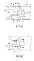
- FIG. 3A is a schematic plan view of the cutter main unit 12 shown in FIG. 1
- FIG. 3B is a bottom view of the cutter main unit 12 shown in FIG. 3A
- FIG. 3C is a schematic transverse sectional view taken along a line IIIC-IIIC in FIG. 3A .
- FIG. 3A a lead passage width variable manipulation portion 31 which manipulates the guide portion 20 in the front-end portion of the movable support body 17 and which varies the width of the lead passage 20a is shown. A detailed configuration of the lead passage width variable manipulation portion 31 will be described later.
- the guide portion 20 in the front-end portion of the movable support body 17 includes a pair of capturing members 32a, 32b which projects outwardly from the front-end portion in parallel to each other along the lengthwise direction of the movable support body 17.
- the pair of capturing members 32a, 32b forms the lead passage 20a therebetween.
- Each of the pair of capturing members 32a, 32b is made of a nonconductive material and its projected end portion is dully pointed.
- an outer-end portion corresponding to projected end portions of the capturing members 32a and 32b is gradually broadened toward the outer end.
- At least one of the capturing members 32a, 32b (in this embodiment, both the capturing members 32a, 32b) is movably provided in the front-end portion of the movable support body 17 so as to vary the width of the lead passage 20a.
- the lead passage width variable manipulation portion 31 includes a lengthwise moving member 31a which is movable along the lengthwise direction of the movable support body 17 and a capturing member driving mechanism 31b which drives the at least one of the capturing members 32a, 32b (in this embodiment, both the capturing members 32a, 32b) so as to vary the width of the lead passage 20a in accordance with the movement of the lengthwise moving member 31a.
- the at least one of the capturing members 32a, 32b (in this embodiment, both the capturing members 32a, 32b) is provided to move in a direction intersecting a lengthwise center line of the movable support body 17 (in this embodiment, a direction orthogonal to the lengthwise center line of the movable support body 17) in parallel with the lengthwise center line with respect to the front-end portion of the movable support body 17, and is urged in a direction in which the width of the lead passage 20a formed between the capturing members 32a, 32b is decreased.
- Moving and urging the pair of capturing members 32a, 32b with respect to the front-end portion of the movable support body 17 can be achieved by a well-known configuration.
- an end face of each base-end portion of the pair of capturing members 32a, 32b is extended in the direction intersecting the lengthwise center line of the movable support body 17 (in this embodiment, the direction orthogonal to the lengthwise center line of the movable support body 17), and a stepped portion having a guide surface extended in the direction intersecting the lengthwise center line (in this embodiment, the direction orthogonal to the lengthwise center line) is formed in the front-end portion of the movable support body 17.
- the pair of capturing members 32a, 32b can be moved in the above-described manner with respect to the front-end portion of the movable support body 17.
- a pair of guide slots 34a, 34b which extends in the direction intersecting the lengthwise center line of the movable support body 17 (in this embodiment, the direction orthogonal to the lengthwise center line) is formed.
- a pair of guide pins 36a, 36b which is inserted in the pair of guide slots 34a, 34b in the pair of regions of the front-end portion of the movable support body 17 is fixed to the base-end portions of the capturing members 32a, 32b.
- a pair of urging members 38a, 38b such as compression coil springs is disposed in the pair of guide slots 34a, 34b in the pair of regions of the front-end portion of the movable support body 17.
- the pair of urging members 38a, 38b urges the pair of guide pins 36a, 36b inserted in the pair of guide slots 34a, 34b to close the pair of guide pins 36a, 36b to the lengthwise center line of the movable support body 17.
- the lengthwise moving member 31a of the lead passage width variable manipulation portion 31 has one end portion located in the front-end portion of the movable support body 17 and the other end portion located in the grip unit 16.
- the capturing member driving mechanism 31b of the lead passage width variable manipulation portion 31 includes a cam member 40 interposed between the one end portion of the lengthwise moving member 31a and the at least one of the capturing members 32a, 32b (in this embodiment, both the capturing members 32a, 32b).
- the cam member 40 includes at least one of a pair of cam surfaces 40a, 40b (in this embodiment, both the cam surfaces 40a, 40b).
- the at least one of the cam surfaces 40a, 40b contacts the at least one of the capturing members 32a, 32b (in this embodiment, both the capturing members 32a, 32b), and moves the at least one of the capturing members 32a, 32b (in this embodiment, both the capturing members 32a and 32b) by the urging force or against the urging force in accordance with the movement of the lengthwise moving member 31a in the lengthwise direction of the movable support body 17.
- edges facing each other in the base-end portions of the capturing members 32a, 32b are formed as cam sliding/contacting edges 42a, 42b which are inclined so as to be gradually separated from each other toward the end face of the base-end portion.
- the cam member 40 is disposed between the cam sliding/contacting edges 42a, 42b of the base-end portions of the capturing members 32a, 32b, and is fixed to the one end portion of the lengthwise moving member 31a.
- the cam surfaces 40a, 40b of the cam member 40 are inclined in accordance with the cam sliding/contacting edges 42a, 42b of the base-end portions of the pair of capturing members 32a, 32b, and the cam surfaces 40a, 40b contact the cam sliding/contacting edges 42a, 42b, respectively.
- the other end portion of the lengthwise moving member 31a, located in the grip unit 16, is coupled to a lead passage width variable slider 44 which projects toward the outside space from the grip unit 16 and which is supported by the grip unit 16 to be movable in the lengthwise direction of the sheath 14a.
- a lead passage width index 46 is disposed at a position on an outer surface of the grip unit 16, the position being adjacent to the lead passage width variable slider 44.
- the lead passage width index 46 displays the width of the lead passage 20a formed between the capturing members 32a, 32b in accordance with the position of the lead passage width variable slider 44.
- the bipolar cutting treatment portion 18 has a pair of electrodes, i.e., an application electrode 48 and a return electrode 50, which are provided in the front-end portion of the movable support body 17.
- the application electrode 48 includes a pair of conductive terminal members 48a, 48b fixed to the pair of capturing members 32a, 32b.
- the pair of conductive terminal members 48a, 48b covers a pair of facing edges forming the lead passage 20a between the capturing members 32a, 32b and the pair of cam sliding/contacting edges 42a and 42b.
- the return electrode 50 includes a conductive terminal member 50a fixed to the front-end portion of the movable support body 17.
- the conductive terminal member 50a covers a region of the front end of the front-end portion of the movable support body 17, the region having a size being larger than the maximum width of the lead passage 20a formed between the capturing members 32a and 32b. This means that the conductive terminal member 50a is disposed at an inner end of the lead passage 20a.
- An intermediate conductive terminal member 52 is fixed to the cam member 40, and the intermediate conductive terminal member 52 covers the pair of cam surfaces 40a, 40b. Accordingly, the intermediate conductive terminal member 52 is electrically connected to the pair of conductive terminal members 48a, 48b of the application electrode 48. The intermediate conductive terminal member 52 is further electrically connected to one end portion of a first lead wire (not shown) extending in the lengthwise direction of the lengthwise moving member 31a in the lengthwise moving member 31a. The other end portion of the first lead wire (not shown) is exposed at the other end portion of the lengthwise moving member 31a disposed in the grip unit 16.
- the lengthwise moving member 31a By making the lengthwise moving member 31a of a conductive material, it can perform the function of the first lead wire (not shown).
- the lead passage variable manipulation slider 44 is made of a nonconductive material.
- the conductive terminal member 50a of the return electrode 50 is electrically connected to one end portion of a second lead wire 54 extending in the lengthwise direction of the movable support body 17 in the movable support body 17.
- the other end portion of the second lead wire 54 is exposed on the other end portion of the lengthwise moving member 31a disposed in the grip unit 16.
- one end portion of a high-frequency power supply connection cable 56 is electrically connected to the other end portion of the first lead wire (not shown), exposed on the other end portion of the lengthwise moving member 31a, for the pair of conductive terminal members 48a, 48b of the application electrode 48, and is also electrically connected to the other end portion of the second lead wire 54, exposed on the other end portion of the movable support body 17, for the return electrode 50.
- the high-frequency power supply connection cable 56 extends toward the outside of the grip unit 16, and a high-frequency power supply S is detachably connected to the extended end portion, i.e., the other end portion, of the high-frequency power supply connection cable 56.
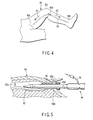
- FIGS. 4 to 8D An example of an operation method for partially harvesting a blood vessel from the inside of the body of the living thing by using the blood vessel harvesting apparatus (harvester) 10 will be described with reference to FIGS. 4 to 8D .
- a large saphenous vein 62 is harvested from the inside of a leg 60 of a human body.
- the large saphenous vein 62 is extended between an ankle 60a and an inguinal region 60b near the cuticule in the leg 60 of the human body.
- an operator cuts a portion of the leg 60 corresponding to the large saphenous vein 62 immediately below a backside of a knee 60c by a surgical knife, and forms an opening 60d having a length of about 2.5 cm. Then, a part of the large saphenous vein 62 corresponding to the opening 60d is separated from the living tissue around the large saphenous vein 62 and is exposed in the opening 60d.
- the trocar 63 After a trocar 63 is inserted in the opening 60d, the trocar 63 is left in the opening 60d as shown in FIG. 5 .
- the trocar 63 is tentatively fixed to the opening 60d by an openable clip 63a.
- the inner end of the trocar 63 is orientated toward the inguinal region 60b as shown by an arrow Al of FIG. 4 , and a blood vessel peeling device (dissector) 64 together with the endoscope (not shown) is inserted into a hole of the trocar 63 through a sealing member 63b located at an outer end of the trocar 63.
- the operator moves the dissector 64 along the large saphenous vein 62 from the opening 60d to the inguinal region 60b of the leg 60 while viewing an endoscope image, and separates a part of the large saphenous vein 62 located in a range from the opening 60d to the inguinal region 60b from the living tissues surrounding the part by using the dissector 64.
- the endoscope and the dissector 64 are tentatively drawn from the hole of the trocar 63, and the inner end of the trocar 63 is orientated toward the ankle 60a as shown by an arrow A2 of FIG. 4 .
- the dissector 64 together with the endoscope (not shown) is inserted again into the hole of the trocar 63 through the sealing member 63b located at the outer end of the trocar 63.
- the operator moves the dissector 64 along the large saphenous vein 62 from the opening 60d to the ankle 60a in the leg 60 while viewing the endoscope image, and separates a part of the large saphenous vein 62 located in a range from the opening 60d to the ankle 60a from the surrounding tissues surrounding the part by using the dissector 64.
- the endoscope and the dissector 64 are drawn from the hole of the trocar 63.
- the large saphenous vein 62 separated from the surrounding tissues in the range of the inguinal region 60b to the ankle 60a in the leg 60 is connected to the surrounding living tissue only by plural collateral veins 62a.
- the operator cuts portions corresponding to both end portions of the large saphenous vein 62 located at the ankle 60a and the inguinal region 60b in the leg 60 by using the surgical knife, and forms openings 60e, 60f. Both end portions of the large saphenous vein 62 are drawn from the openings 60e, 60f and tied with strings respectively.
- the operator orientates the inner end of the trocar 63 toward the inguinal region 60b as shown by the arrow Al of FIG. 4 , and inserts the insertion unit 14 of the blood vessel harvesting apparatus (harvester) 10 shown in FIGS. 1 and 2 together with the endoscope (not shown) in the hole of the trocar 63 through the sealing member 63b located at the outer end of the trocar 63. Then, the operator moves the front-end portion of the insertion unit 14 along the large saphenous vein 62 from the opening 60d to the inguinal region 60b in the leg 60 while viewing the endoscope image.
- the operator manipulates the retainer manipulating slider 26 of the grip unit 16 of the blood vessel harvesting apparatus (harvester) 10 to sequentially press neighborhoods of plural portions of the large saphenous vein 62, at which the plural collateral veins 62a are branched from the large saphenous vein 62, by the blood vessel retainer 22 of the front-end portion of the insertion unit 14, and advances the cutter manipulation slider 24 of the grip unit 16 toward the insertion unit 14 to project the movable support body 17 of the cutter main unit 12 from the front-end portion of the insertion unit 14.
- the movable support body 17 advanced from the front-end portion of the insertion unit 14 sequentially introduces the plural branching ends of the plural collateral veins 62a into the lead passage 20a of the guide portion 20, and the bipolar cutting treatment portion 18 located at the inner end of the lead passage 20a is sequentially pressed against and cuts the introduced branching ends of the plural collaterals 62a and at the same time cauterizes the cut surfaces of the large saphenous vein 62.
- the operator tentatively draws the blood vessel harvesting apparatus 10 together with the endoscope from the hole of the trocar 63, and orientates the inner end of the trocar 63 toward the ankle 60a as shown by the arrow A2 of FIG. 4 .
- the operator inserts the blood vessel harvesting apparatus (harvester) 10 together with the endoscope into the hole of the trocar 63 through the sealing member 63b located at the outer end of the trocar 63 again.
- the operator moves the front-end portion of the insertion unit 14 along the large saphenous vein 62 from the opening 60d to the ankle 60a in the leg 60 while viewing the endoscope image.
- the operator manipulates the retainer manipulating slider 26 of the grip unit 16 of the blood vessel harvesting apparatus 10 to sequentially press the neighborhoods of the plural portions on the large saphenous vein 62, at which the plural collateral veins 62a are branched from the large saphenous vein 62, by the blood vessel retainer 22 of the front-end portion of the insertion unit 14, and advances the cutter manipulation slider 24 of the grip unit 16 toward the insertion unit 14 to project the movable support body 17 of the cutter main unit 12 from the front-end portion of the insertion unit 14.
- the movable support body 17 advanced from the front-end portion of the insertion unit 14 sequentially introduces the plural branching ends of the plural collateral veins 62a into the lead passage 20a of the guide portion 20, and the bipolar cutting treatment portion 18 located at the inner end of the lead passage 20a is sequentially pressed against and cuts the introduced branching ends of the plural collaterals 62a and at the same time cauterizes the cut surfaces of the large saphenous vein 62.
- the blood vessel harvesting apparatus (harvester) 10 together with the endoscope is drawn along with the trocar 63 from the opening 60d. Further, the both end portions of the large saphenous vein 62 are cut between the hemostatic portions of the both end portions at the opening 60e of the ankle 60a and the opening 60f of the inguinal region 60b in the leg 60, and the large saphenous vein 62 is drawn from the opening 60e of the ankle 60a or the opening 60f of the inguinal region 60b in the leg 60. Then, the opening 60a of the knee 64, the opening 60e of the ankle 60a, and the opening 60f of the inguinal region 60b of the leg 60 are closed by well-known closing means and the example of the operation method is finished.
- the plural collateral veins 62a of the large saphenous vein 62 have diameters being different from each other.
- the blood vessel harvesting apparatus (harvester) 10 can change the width of the lead passage 20a formed between the capturing members 32a, 32b by moving the pair of capturing members 32a, 32b of the guide portion 20 in a direction in which the capturing members 32a, 32b intersect the lengthwise center line of the movable support body 17 (in this embodiment, the direction orthogonal to the lengthwise center line).
- the lead passage 20a can easily fit each of the plural collateral veins 62a having the different diameters, and therefore the bipolar cutting treatment portion 18 provided at the inner end of the lead passage 20a can easily cut each of the plural collateral veins 62a having the different diameters and further can easily cauterize the cut surfaces on the large saphenous vein 62.
- the cam member 40 of the capturing member driving mechanism 31b connected to the lead passage variable manipulation slider 44 through the lengthwise moving member 31a is disposed farthest away from the front-end surface of the front-end portion of the movable support body 17 in the movable range along the lengthwise center line of the movable support body 17 in the front-end portion of the movable support body 17 as shown in FIG. 8A .
- the pair of capturing members 32a, 32b of the guide portion 20 which is urged in the direction in which the lead passage 20a formed therebetween is decreased by the urging members 38a, 38b and the pair of cam sliding/contacting edges 42a, 42b of which abuts on the pair of cam surfaces 40a and 40b of the cam member 40, is disposed closest to the lengthwise center line of the movable support body 17 in the front-end portion of the movable support body 17 in the movable range in the direction intersecting the lengthwise center line of the movable support body 17 (in this embodiment, the direction which is orthogonal to the lengthwise center line) as shown in FIGS. 8A and 8B . That is, the lead passage 20a formed between the capturing members 32a, 32b has the smallest width.
- the cam member 40 of the capturing member driving mechanism 31b connected to the lead passage variable manipulation slider 44 through the lengthwise moving member 31a is disposed closest to the front-end surface of the front-end portion of the movable support body 17 in the movable range along the lengthwise center line of the movable support body 17 on the front-end portion of the movable support body 17 as shown in FIG. 8C .
- the pair of capturing members 32a, 32b of the guide portion 20 can be disposed at any position in the movable range along the direction intersecting the lengthwise center line of the movable support body 17 in the front-end portion of the movable support body 17 (in this embodiment, the direction which is orthogonal to the lengthwise center line), and therefore the width of the lead passage 20a formed between the capturing members 32a, 32b can be set arbitrarily in the range between the smallest width shown in FIGS. 8A and 8B and the largest width shown in FIGS. 8C and 8D .
- the width of the lead passage 20a corresponding to the position of the lead passage variable manipulation slider 44 on the grip unit 16 can be recognized easily by the lead passage width index 46 disposed adjacent to the lead passage variable manipulation slider 44 on the outer surface of the grip unit 16.
- the width of the lead passage 20a can be set to the width corresponding to the diameter of the branching end of the collateral vein 62a to be introduced into the lead passage 20a, and then the branching end of the collateral vein 62a can be introduced into the lead passage 20a.
- the width of the lead passage 20a is set slightly larger than the diameter of the branching end of the collateral vein 62a to be introduced into the lead passage 20a, and then the width of the lead passage 20a can be set to the width corresponding to the diameter of the branching end of the collateral vein 62a introduced into the lead passage 20a after the branching end of the collateral vein 62a is introduced into the lead passage 20a.
- the width of the lead passage 20a can be set to the width corresponding to the diameter of the branching end of the collateral vein 62a to be introduced into the lead passage 20a
- the pair of conductive terminal members 48a, 48b of the application electrode 48 which covers the pair of facing edges of the pair of capturing members 32a, 32b forming the lead passage 20a therebetween
- the conductive terminal member 50a of the return electrode 50 which covers the front end (i.e., the inner end of the lead passage 20a) of the front-end portion of the movable support body 17 can be pressed surely against the branching end of the collateral vein 62a introduced into the inner end of the lead passage 20a.
- the branching end of the collateral vein 62a introduced into the inner end of the lead passage 20a can be cut in the bipolar cutting treatment portion 18 at the inner end of the lead passage 20a by the high-frequency current passed from the pair of conductive terminal members 48a, 48b of the application electrode 48 to the conductive terminal member 50a of the return electrode 50, and the cut surface can be cauterized (that is, stop bleeding).
- the blood vessel harvesting operation described above with reference to FIGS. 4 to 7 can be performed quickly and the operated point in the patient body is early recovered after the operation.
- FIGS. 9A to 9D A most part of a configuration of the blood vessel harvesting apparatus (harvester) 10 according to the second embodiment is the same as that of the configuration of the blood vessel harvesting apparatus (harvester) 10 according to the first embodiment described above with reference to FIGS. 1 to 8D .
- the same components of the blood vessel harvesting apparatus (harvester) 10 according to the second embodiment as those of the blood vessel harvesting apparatus (harvester) 10 according to the first embodiment are designated by the same reference numerals as those designating the same components of the blood vessel harvesting apparatus (harvester) 10 according to the first embodiment, and the detailed descriptions thereof are omitted.
- the blood vessel harvesting apparatus (harvester) 10 according to the second embodiment differs from the blood vessel harvesting apparatus (harvester) 10 according to the first embodiment in the configuration of the cutter main unit 12.
- a pair of capturing members 32'a, 32'b of the guide portion 20 provided in and projected from the front-end portion of the movable support body 17 is rotational with respect to the front-end portion of the movable support body 17 in order to be able to vary the width of the lead passage 20a formed between the capturing members 32'a, 32'b.
- portions of the base-end portions of the capturing members 32'a, 32'b facing each other are rotationally supported in the front-end portion of the movable support body 17 by a rotation center pin 74 in a state in which the portions are overlapped with each other.
- Each of the capturing members 32'a, 32'b is made of a nonconductive material, and each projected end portion of the capturing members 32a, 32b is dully pointed.
- the edges of the base-end portions of the capturing members 32'a, 32'b facing each other are formed as inclined surfaces which are gradually separated from each other toward the end face of the base-end portion, but are different from the edges of the base-end portions of the capturing members 32a, 32b of the first embodiment facing each other and formed as the pair of inclined cam sliding/contacting edges 42a, 42b.
- the rotation center pin 74 is made of a conductive material.
- a first lead wire 76 extends from the front-end portion to the base-end portion in the movable support body 17, and the base-end portion of the rotation center pin 74 is electrically connected to one end portion of the first lead wire 76 located in the front-end portion of the movable support body 17.
- the high-frequency power supply connection cable 56 (see FIGS. 1 and 2 ) is not connected to the lengthwise moving member 31a of the lead passage variable manipulation portion 31, but the high-frequency power supply connection cable 56 (see FIGS. 1 and 2 ) is connected to the other end portion of the first lead wire 76 located in the grip unit 16.
- the lead passage variable manipulation portion 31a interposes a link mechanism 78 between one end portion of the lengthwise moving member 31a located in the front-end portion of the movable support body 17 and the base-end portions of the pair of capturing members 32'a, 32'b.
- the link mechanism 78 includes a pair of link members 78a, 78b each of which has both end portions rotationally coupled to the one end portion of the lengthwise moving member 31a and each base-end portion of the capturing members 32'a, 32'b, and provides the capturing member driving mechanism 31b for driving the at least one of the capturing members 32a, 32b (in this embodiment, both the capturing members 32a, 32b) in accordance with the movement of the lengthwise moving member 31a to vary the width of the lead passage 20a.
- the blood vessel harvesting apparatus (harvester) 10 rotates the pair of capturing members 32'a, 32'b of the guide portion 20 in the direction intersecting the lengthwise center line of the movable support body 17, so that the width of the lead passage 20a formed between the capturing members 32'a, 32'b can be changed. Accordingly, the lead passage 20a can be fit easily each of the plural collateral veins 62a of the large saphenous vein 62 having the different diameters and shown in FIG. 7 , and therefore the bipolar cutting treatment portion 18 provided at the inner end of the lead passage 20a can easily cut each of the plural collateral veins 62a having the different diameters and can cauterize the cut surface easily.
- the pair of link members 78a, 78b of the link mechanism 78 of the capturing member driving mechanism 31b connected to the lead passage variable manipulation slider 44 through the lengthwise moving member 31a disposes the pair of capturing members 32'a, 32'b at positions being closest to the lengthwise center line in the rotational range in a direction in which the pair of capturing members 32'a, 32'b intersects the lengthwise center line of the movable support body 17 in the front-end portion of the movable support body 17 as shown in FIGS. 9A and 9B . That is, the lead passage 20a formed between the capturing members 32'a, 32'b has the smallest width.
- the pair of link members 78a, 78b of the link mechanism 78 of the capturing member driving mechanism 31b connected to the lead passage variable manipulation slider 44 through the lengthwise moving member 31a disposes the pair of capturing members 32'a, 32'b at positions being farthest away from the lengthwise center line in the rotational range in the direction in which the pair of capturing members 32'a, 32'b intersects the lengthwise center line of the movable support body 17 in the front-end portion of the movable support body 17 as shown in FIGS. 9C and 9D . That is, the lead passage 20a formed between the capturing members 32'a, 32'b has the largest width.
- the pair of capturing members 32'a, 32'b of the guide portion 20 can be disposed at any position in the movable range along the direction intersecting the lengthwise center line of the movable support body 17 in the front-end portion of the movable support body 17, and therefore the width of the lead passage 20a formed between the capturing members 32'a, 32'b can be set arbitrarily in the range between the smallest width shown in FIGS. 9A and 9B and the largest width shown in FIGS. 9C and 9D .
- the width of the lead passage 20a corresponding to the position of the lead passage variable manipulation slider 44 in the grip unit 16 can be recognized easily by the lead passage width index 46 disposed adjacent to the lead passage variable manipulation slider 44 on the outer surface of the grip unit 16 as shown in FIG. 3A .
- the width of the lead passage 20a can be set to the width corresponding to the diameter of the branching end of the collateral vein 62a to be introduced into the lead passage 20a, and then the branching end of the collateral vein 62a can be introduced into the lead passage 20a.
- the width of the lead passage 20a is set slightly larger than the diameter of the branching end of the collateral vein 62a to be introduced into the lead passage 20a, and then the width of the lead passage 20a can be set to the width corresponding to the diameter of the branching end of the collateral vein 62a introduced into the lead passage 20a after the branching end of the collateral vein 62a is introduced into the lead passage 20a.
- the width of the lead passage 20a can be set to the width corresponding to the diameter of the branching end of the collateral vein 62a to be introduced into the lead passage 20a, the pair of conductive terminal members 48'a, 48'b of the application electrode 48, which covers the pair of facing edges of the pair of capturing members 32'a, 32'b forming the lead passage 20a therebetween, and the conductive terminal member 50a of the return electrode 50, which covers the front end (i.e., the inner end of the lead passage 20a) of the front-end portion of the movable support body 17, can be pressed surely against the branching end of the collateral vein 62a introduced into the inner end of the lead passage 20a.
- the branching end of the collateral vein 62a introduced into the inner end of the lead passage 20a can be cut in the bipolar cutting treatment portion 18 at the inner end of the lead passage 20a by the high-frequency current passed from the pair of conductive terminal members 48'a, 48'b of the application electrode 48 to the conductive terminal member 50a of the return electrode 50, and the cut surface can be cauterized (that is, stop bleeding).
- the blood vessel harvesting operation described above with reference to FIGS. 4 to 7 can be performed quickly and the operated point in the patient body is early recovered after the operation.
- the pair of capturing members 32'a, 32'b is not urged toward the direction in which the width of the lead passage 20a formed between the capturing members 32'a, 32'b is decreased.
- the pair of capturing members 32'a, 32'b can be urged in this manner by bridging the well-known urging member between the pair of capturing members 32'a, 32'b.
- the well-known urging member can be provided by a torsion coil spring 79 which is wounded on the rotation center pin 74 and which has two legs engaged with the base-end portions of the capturing members 32'a, 32'b.
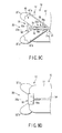
- FIGS. 10A and 10B a blood vessel harvesting apparatus (harvester) 10 according to a third embodiment of the bipolar cutter of this invention will be described with reference to FIGS. 10A and 10B .
- the blood vessel harvesting apparatus (harvester) 10 includes the insertion unit 14 inserted in the body of the living thing (in this embodiment, in the leg of the human), the bipolar cutting treatment portion 18 provided in the front-end portion of the insertion unit 14, and the guide portion 20 including the lead passage which is provided in the front-end portion of the insertion unit 14, which captures the living tissue (in this embodiment, the blood vessel) of the cutting target in the body of the living thing and guides the living tissue to the bipolar cutting treatment portion 18.
- the blood vessel harvesting apparatus (harvester) 10 differs from the blood vessel harvesting apparatus (harvester) 10 according to the first embodiment shown in FIG. 1 in the configuration of the cutter main unit 12 provided in the front-end portion of the movable support body 17 in the front-end portion of the insertion unit 14.
- the guide portion 20 of this embodiment includes at least three capturing members 82a, 82b, and 82c (in this embodiment, three capturing members) which are formed in the front-end surface of the front-end portion of the movable support body 17 to extend in parallel with each other along the lengthwise center line of the movable support body 17 from at least three positions (in this embodiment, three positions) separated from each other in the direction orthogonal to the lengthwise center line of the movable support body 17.
- Plural lead passages 84a, 84b (in this embodiment, two lead passages) are formed between the at least three capturing members 82a, 82b, and 82c (in this embodiment, three capturing members).
- the plural lead passages 84a, 84b (in this embodiment, two lead passages) have different widths.
- Each front-end portion of the at least three capturing members 82a, 82b, and 82c (in this embodiment, three capturing members) is formed in a dully pointed shape. Further, in the this embodiment, an extending length of the capturing member 82b located in the center is longer than an extending length of each of the two capturing members 82a, 82c located on both sides of the capturing member 82b.
- the bipolar cutting treatment portion 18 includes an application electrode 86 fixed to the at least three capturing members 82a, 82b, and 82c (in this embodiment, three capturing members) and a return electrode 88 fixed to the front-end portion of the movable support body 17.
- the application electrode 86 extends along or the neighborhoods of the facing edges which regulate each of the lead passages 84a, 84b respectively, and is electrically connected to one end portion of a first lead wire 90 in the front-end portion of the movable support body 17.
- the first lead wire 90 extends from the front-end portion to the base-end portion of the movable support body 17 in the movable support body 17.
- the return electrode 88 is exposed at the inner end of each of the plural lead passages 84a, 84b (in this embodiment, two lead passages) in the front-end portion of the movable support body 17, and is electrically connected to one end portion of a second lead wire 92.
- the second lead wire 92 extends from the front-end portion to the base-end portion of the movable support body 17 in the movable support body 17.
- the high-frequency power supply connection cable 56 is connected to the other end portion of the first lead wire 90 for the application electrode 86 and the other end portion of the second lead wire 92 for the return electrode 88 in the base-end portion of the movable support body 17 in the grip unit 16 (see FIG. 1 ).
- the blood vessel harvesting apparatus (harvester) 10 of this embodiment includes neither the lead passage variable manipulation slider 44 shown in FIGS. 1 and 3A nor the lengthwise moving member 31a and capturing member driving mechanism 31b of the lead passage variable manipulation portion 31 shown in FIG. 3A .
- the blood vessel harvesting apparatus (harvester) 10 of the first embodiment the configuration of the cutter main unit 12 of which is shown in FIGS. 3A to 3C
- the blood vessel harvesting apparatus (harvester) 10 of the second embodiment the configuration of the cutter main unit 12 of which is shown in FIGS. 9A to 9D
- the blood vessel harvesting apparatus (harvester) 10 of this embodiment the configuration of the cutter main unit 12 of which is shown in FIGS. 10A and 10B , has a simple configuration.
- the movable support body 17 of the insertion unit 14 is manipulated such that the branching end of the collateral vein 62a to be cut is introduced into the lead passage 84a or 84b having the width corresponding to the diameter of the branching end of the collateral vein 62a to be cut as shown in FIG. 5 .
- the application electrode 86 which is along the edges of the two capturing members 82a, 82b, or 82b, 82c facing each other and forming the lead passage 84a or 84b therebetween, and the return electrode 88, which is exposed at the inner end of each of the lead passages 84a and 84b in the front end of the front-end portion of the movable support body 17, can be surely brought close to or pressed against the branching end of the collateral vein 62a introduced into the lead passage 84a or 84b.
- the branching end of the collateral vein 62a introduced into the inner end of the lead passage 84a or 84b can be cut in the bipolar cutting treatment portion 18 at the inner end of the lead passage 84a or 84b by an high-frequency current passed from the application electrode 86 to the return electrode 88, and the cut surface can be cauterized (i.e., stop bleeding).
- the blood vessel harvesting operation described above with reference to FIGS. 4 to 7 can be performed quickly and the operated point in the patient body is early recovered after the operation.
- FIGS. 11A to 11D a blood vessel harvesting apparatus (harvester) 10 according to a fourth embodiment of the bipolar cutter of this invention will be described with reference to FIGS. 11A to 11D .
- the blood vessel harvesting apparatus (harvester) 10 of the fourth embodiment includes the insertion unit 14 inserted in a body of a living thing (in the fourth embodiment, in a leg of a human), the bipolar cutting treatment portion 18 provided on the front-end portion of the insertion unit 14, and the guide portion 20 including the lead passage provided in the front-end portion of the insertion unit 14.
- the lead passage captures the living tissue (in the fourth embodiment, the blood vessel) of the cutting target in the living body and guides the living tissue to the bipolar cutting treatment portion 18.
- the blood vessel harvesting apparatus (harvester) 10 of the fourth embodiment differs from the blood vessel harvesting apparatus (harvester) 10 of the first embodiment shown in FIG. 1 in the configuration of the cutter main unit 12 provided on the front-end portion of the movable support body 17 in the front-end portion of the insertion unit 14.
- the guide portion 20 provided on the front-end portion of the movable support body 17 includes a pair of capturing members 102a, 102b projecting outward from the front-end portion in parallel with each other along the lengthwise direction of the movable support body 17.
- the capturing members 102a, 102b form the lead passage 20a therebetween.
- Each of the capturing members 102a, 102b is made of the nonconductive material, and each projecting end portion of the capturing members 102a, 102b is dully pointed.
- each base-end surface of the base-end portions of the capturing members 102a, 102b extends in a direction intersecting the lengthwise center line of the movable support body 17 (in the fourth embodiment, the direction orthogonal to the lengthwise center line).
- At least one of the capturing members 102a, 102b (in the fourth embodiment, both the capturing members 102a, 102b) is provided on the front-end portion of the movable support body 17 so as to be movable in parallel to the lengthwise center line of the movable support body 17 in the direction intersecting the lengthwise center line (in the fourth embodiment, the direction orthogonal to the lengthwise center line), and is urged toward the direction in which the width of the lead passage 20a formed between the capturing members 102a, 102b is decreased.
- a pair of guide grooves 104a, 104b whose planar shape is formed in a square is formed in a pair of regions on the front-end portion of the movable support body 17 corresponding to the base-end portions of the pair of capturing members 102a, 102b.
- one side located far away from the front-end surface of the front-end portion of the movable support body 17 is formed as a guide surface extending in a direction intersecting the lengthwise center line of the movable support body 17 (in the fourth embodiment, the direction orthogonal to the lengthwise center line).
- a pair of sliding members 106a, 106b inserted in the pair of guide grooves 104a, 104b in the pair of regions of the front-end portion of the movable support body 17 is fixed to the base-end portions of the capturing members 102a, 102b.
- Each planar shape of the sliding members 106a, 106b is also formed in the square.
- one side located far away from the front-end surface of the front-end portion of the movable support body 17 is formed as a sliding surface extending in a direction intersecting the lengthwise center line of the movable support body 17 (in the fourth embodiment, the direction orthogonal to the lengthwise center line).
- Each of the sliding members 106a, 106b can be moved in the direction intersecting the lengthwise center line of the movable support body 17 (in the fourth embodiment, the direction orthogonal to the lengthwise center line) in each of the guide grooves 104a, 104b while each sliding surface is sliding on the guide surface of each of the guide grooves 104a, 104b.
- Urging members 108 such as compression coil springs are disposed in the pair of guide grooves 104a, 104b of the pair of regions on the front-end portion of the movable support body 17 to urge the pair of sliding members 106a, 106b inserted in the pair of guide grooves 104a, 104b such that the sliding members 106a, 106b are closed to the lengthwise center line of the movable support body 17.
- the urging members 108 urge the pair of capturing members 102a, 102b so as to decrease the width of the lead passage 20a formed between the capturing members 102a, 102b.
- the bipolar cutting treatment portion 18 provided in the front-end portion of the movable support body 17 includes a pair of electrodes, i.e., an application electrode 110 and a return electrode 112, which are provided in the front-end portion of the movable support body 17.
- the application electrode 110 includes a pair of conductive terminal members 110a, 110b fixed to the pair of capturing members 102a, 102b.
- the pair of conductive terminal members 110a, 110b covers the pair of facing edges forming the lead passage 20a therebetween and the pair of base-end edges of the base-end portions on the capturing members 102a, 102b.
- the return electrode 112 includes a conductive terminal member 112a fixed to the front-end portion of the movable support body 17.
- the conductive terminal member 112a covers a size larger than the maximum width of the lead passage 20a formed between the capturing members 102a, 102b, at the front end of the front-end portion of the movable support body 17. This means that the conductive terminal member 112a is disposed at the inner end of the lead passage 20a.
- An intermediate conductive terminal member 114 is also disposed on the front-end portion of the movable support body 17, and extends in the direction intersecting the lengthwise center line of the movable support body 17 (in the fourth embodiment, the direction orthogonal to the lengthwise center line) along the base-end surface of each base-end portion of the capturing members 102a, 102b.
- the pair of conductive terminal members 110a, 110b of the application electrode 110 which covers the base-end surface of each base-end portion of the capturing members 102a, 102b contacts the intermediate conductive terminal member 114. Accordingly, the intermediate conductive terminal member 114 is electrically connected to the pair of conductive terminal members 110a, 110b of the application electrode 110.
- the intermediate conductive terminal member 114 is also electrically connected to a first lead wire 116 extending along the lengthwise direction of the movable support body 17 in the movable support body 17.
- the other end portion of the first lead wire 116 is exposed on the other end portion of the movable support body 17 disposed in the grip unit 16 (see FIGS. 1 and 2 ).
- the conductive terminal member 112a of the return electrode 112 is electrically connected to one end portion of a second lead wire 118 extending along the lengthwise direction of the movable support body 17 in the movable support body 17.
- the other end portion of the second lead wire 118 is exposed on the other end portion of the movable support body 17 disposed in the grip unit 16 (see FIGS. 1 and 2 ).
- the other end portion of the first lead wire 116 for the pair of conductive terminal members 110a and 110b of the application electrode 110, exposed on the other end portion of the movable support body 17, and the other end portion of the second lead wire 118 for the return electrode 112, exposed on the other end portion of the movable support body 17 are electrically connected to one end portion of the high-frequency power supply connection cable 56 (see FIGS. 1 and 2 ).
- the blood vessel harvesting apparatus (harvester) 10 of the fourth embodiment includes neither the lead passage variable manipulation slider 44 shown in FIGS. 1 and 3A nor the lengthwise moving member 31a and capturing member driving mechanism 31b (cam member 40) of the lead passage variable manipulation portion 31 shown in FIG. 3A .
- the blood vessel harvesting apparatus (harvester) 10 of the fourth embodiment has more simple configuration in comparison with the blood vessel harvesting apparatus (harvester) 10 of the first embodiment, the configuration of the cutter main unit 12 of which is shown in FIGS. 3A to 3C , and the blood vessel harvesting apparatus (harvester) 10 of the second embodiment, the configuration of the cutter main unit 12 of which is shown in FIGS. 9A to 9D .
- the capturing members 102a, 102b of the blood vessel harvesting apparatus (harvester) 10 of the fourth embodiment are disposed at positions closest to each other by the urging forces of the urging members 108, and the width of the lead passage 20a formed between the capturing members 102a, 102b becomes narrowest at that time.
- the capturing members 102a, 102b of the blood vessel harvesting apparatus (harvester) 10 of the fourth embodiment are disposed at positions farthest away from each other against the urging forces of the urging members 108, and the width of the lead passage 20a formed between the capturing members 102a, 102b becomes broadest at that time.
- the movable support body 17 of the insertion unit 14 is manipulated such that the branching end of the collateral vein 62a to be cut as shown in FIG. 5 is introduced into the lead passage 20a.
- the diameter of the branching end of the collateral vein 62a introduced into the lead passage 20a is larger than the narrowest width of the lead passage 20a formed between the capturing members 102a, 102b
- the pair of capturing members 102a, 102b is pressed by the branching end of the collateral vein 62a introduced into the lead passage 20a, and is opened in the direction in which the capturing members 102a, 102b are separated from each other against the urging forces of the urging members 108.
- the width of the lead passage 20a formed between the capturing members 102a, 102b is automatically adjusted in accordance with the diameter of the branching end of the collateral 62a introduced into the lead passage 20a.
- the automatic adjustment of the width of the lead passage 20a formed between the capturing members 102a, 102b is performed in a range of the diameter of the branching end of the collateral vein 62a introduced into the lead passage 20a between the narrowest width of the lead passage 20a shown in FIGS. 11A and 11B and the broadest width of the lead passage 20a shown in FIGS. 11C and 11D .
- the pair of conductive terminal members 110a, 110b of the application electrode 110 along the facing edges of the two capturing members 102a, 102b forming the lead passage 20a therebetween and the conductive terminal member 112a of the return electrode 112 exposed on the inner end of the lead passage 20a at the front end of the front-end portion of the movable support body 17 can surely be brought close to or pressed against the branching end of the collateral vein 62a introduced into the lead passage 20a.
- the branching end of the collateral vein 62a introduced into the inner end of the lead passage 20a can be cut by the high-frequency current passed from the pair of conductive terminal members 110a, 110b of the application electrode 110 to the conductive terminal member 112a of the return electrode 112 and the cut surface can be cauterized (i.e., stop bleeding) in the bipolar cutting treatment portion 18 at the inner end of the lead passage 20a.
- the blood vessel harvesting operation described with reference to FIGS. 4 to 7 can be performed quickly and the operated point in the patient body is early recovered after the operation.
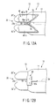
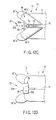
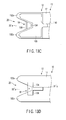
- a blood vessel harvesting apparatus (harvester) 10 according to a fifth embodiment of the bipolar cutter of this invention will be described with reference to FIGS. 12A to 12D .
- the blood vessel harvesting apparatus (harvester) 10 of the fifth embodiment includes the insertion unit 14 inserted in the body of the living thing (in the fifth embodiment, in the leg of the human), the bipolar cutting treatment portion 18 provided in the front-end portion of the insertion unit 14, and the guide portion 20 including the lead passage provided in the front-end portion of the insertion unit 14 to capture the living tissue (in the fifth embodiment, the blood vessel) of the cutting target in the body of the living thing and to guide the living tissue to the bipolar cutting treatment portion 18.
- the blood vessel harvesting apparatus (harvester) 10 of the fifth embodiment differs from the blood vessel harvesting apparatus (harvester) 10 of the first embodiment shown in FIG. 1 in the configuration of the cutter main unit 12 provided in the front-end portion of the movable support body 17 in the front-end portion of the insertion unit 14.
- the cutter main unit 12 of the fifth embodiment is configured by removing the lead passage variable manipulation portion 31 from the blood vessel harvesting apparatus (harvester) 10 of the second embodiment shown in FIGS. 9A and 9D and by urging the pair of capturing members 32'a, 32'b provided in the movable support body 17 in the guide portion 20 to be rotational about the rotation center pin 74 such that the width of the lead passage 20a formed between the capturing members 32'a, 32'b is decreased.
- Urging of the pair of capturing members 32'a, 32'b can be performed by bridging the well-known urging member between the pair of capturing members 32'a, 32'b, as described in the blood vessel harvesting apparatus (harvester) 10 of the second embodiment.
- the well-known urging member can be provided by a torsion coil spring 79 which is wounded around the rotation center pin 74 and which has two legs engaged with the base-end portions of the capturing members 32'a, 32'b.
- the blood vessel harvesting apparatus (harvester) 10 of the fifth embodiment includes neither the lead passage variable manipulation slider 44 shown in FIGS. 1 and 3A nor the lengthwise moving member 31a and capturing member driving mechanism 31b (the link members 78a, 78b of the ink mechanism 78) of the lead passage variable manipulation portion 31 shown in FIG. 9A .
- the blood vessel harvesting apparatus (harvester) 10 of the fifth embodiment has more simple configuration in comparison with the blood vessel harvesting apparatus (harvester) 10 of the first embodiment, the configuration of the cutter main unit 12 of which is shown in FIGS. 3A to 3C , and the blood vessel harvesting apparatus (harvester) 10 of the second embodiment, the configuration of the cutter main unit 12 of which is shown in FIGS. 9A to 9D .
- the front-end portions of the capturing members 32'a, 32'b of the blood vessel harvesting apparatus (harvester) 10 of the fifth embodiment are disposed at positions closest to each other by the urging force of the urging member 79, and the width of the lead passage 20a formed between the front-end portions of the capturing members 32'a, 32'b becomes narrowest at that time.
- the front-end portions of the capturing members 32'a, 32'b of the blood vessel harvesting apparatus (harvester) 10 of the fifth embodiment are disposed at positions farthest away from each other against the urging force of the urging member 79, and the width of the lead passage 20a formed between the front-end portions of the capturing members 102a and 102b becomes broadest at that time.
- the movable support body 17 of the insertion unit 14 is manipulated such that the branching end of the collateral vein 62a to be cut as shown in FIG. 5 is introduced into the lead passage 20a.
- the diameter of the branching end of the collateral vein 62a introduced into the lead passage 20a is larger than the narrowest width of the lead passage 20a formed between the capturing members 32'a, 32'b
- the front-end portions of the capturing members 32'a, 32'b are pressed by the branching end of the collateral vein 62a introduced into the lead passage 20a and are opened in the direction in which the capturing members 32'a, 32'b are separated from each other against the urging force of the urging member 79.
- the width of the lead passage 20a formed between the capturing members 32'a, 32'b is automatically adjusted in accordance with the diameter of the branching end of the collateral 62a introduced into the lead passage 20a.
- Such an automatic adjustment of the width of the lead passage 20a formed between the capturing members 32'a, 32'b in accordance with the diameter of the branching end of the collateral vein 62a introduced into the lead passage 20a is performed in a range of the diameter of the branching end of the collateral 62a between the narrowest width of the lead passage 20a shown in FIGS. 12A and 12B and the broadest width of the lead passage 20a shown in FIGS. 12C and 12D .
- the pair of conductive terminal members 48'a, 48'b of the application electrode 48 along the facing edges of the two capturing members 32'a, 32'b forming the lead passage 20a therebetween and the conductive terminal member 50a of the return electrode 50 exposed on the inner end of the lead passage 20a in the front end of the front-end portion of the movable support body 17 can be surely brought close to or pressed against the branching end of the collateral vein 62a introduced into the lead passage 20a.
- the branching end of the collateral vein 62a introduced into the inner end of the lead passage 20a can be cut by the high-frequency current passed from the pair of conductive terminal members 48'a, 48'b of the application electrode 48 to the conductive terminal member 50a of the return electrode 50 and the cut surface can be cauterized (i.e., stop bleeding) in the bipolar cutting treatment portion 18 at the inner end of the lead passage 20a.
- the blood vessel harvesting operation described with reference to FIGS. 4 to 7 can be performed quickly and the operated point in the patient body is early recovered after the operation.
- the blood vessel harvesting apparatus (harvester) 10 according to a sixth embodiment of the bipolar cutter of the invention will be described with reference to FIGS. 13A to 13D .
- the blood vessel harvesting apparatus (harvester) 10 of the sixth embodiment includes the insertion unit 14 inserted in the body of the living thing (in the sixth embodiment, in the leg of the human), the bipolar cutting treatment portion 18 provided in the front-end portion of the insertion unit 14, and the guide portion 20 including a lead passage 20'a provided in the front-end portion of the insertion unit 14 to capture the living tissue (in the sixth embodiment, the blood vessel) of the cutting target in the body of the living thing and to guide the living tissue to the bipolar cutting treatment portion 18.
- the blood vessel harvesting apparatus (harvester) 10 of the sixth embodiment differs from the blood vessel harvesting apparatus (harvester) 10 of the first embodiment shown in FIG. 1 in the configuration of the cutter main unit 12 provided on the front-end portion of the movable support body 17 in the front-end portion of the insertion unit 14.
- the lead passage 20'a of the guide portion 20 of this embodiment is formed in a shape in which the lead passage 20'a is enlarged as the lead passage 20'a recedes from the front-end portion of the insertion unit 14.
- the guide portion 20 of the sixth embodiment includes two capturing members 132a, 132b formed in the front-end surface of the front-end portion of the movable support body 17 and extending in parallel with each other along the lengthwise center line of the movable support body 17 from two positions separated from each other in the direction orthogonal to the lengthwise center line of the movable support body 17.
- the lead passage 20'a is formed between the two capturing members 132a, 132b.
- the lead passage 20'a is formed in a substantially V-shape.
- the guide portion 20 of this embodiment also includes a lead passage width regulating member 134 which can be moved between the inner end of the lead passage 20'a and a position close to the outer end of the lead passage 20'a along the lengthwise center line (i.e., the lengthwise center line of the movable support body 17) of the insertion unit 14.
- the lead passage width regulating member 134 is fixed to one end portion of a lengthwise moving member 31'a having the configuration similar to that of the lengthwise moving member 31a of the lead passage width variable manipulation portion 31 shown in FIG. 3A .
- the other end portion of the lengthwise moving member 31'a is fixed to the lead passage variable manipulation slider 44 in the grip unit 16.
- the bipolar cutting treatment portion 18 includes an application electrode 136 fixed to the two capturing members 132a, 132b and a return electrode 138 fixed to the lead passage width regulating member 134.
- the application electrode 136 extends along facing edges regulating the lead passage 20'a or the neighborhoods of the facing edges in one surface of each of the two capturing members 132a, 132b, and is electrically connected to one end portion of a first lead wire 140 in the front-end portion of the movable support body 17.
- the first lead wire 140 extends from the front-end portion to the base-end portion of the movable support body 17 in the movable support body 17.
- the return electrode 138 covers the front-end surface of the front-end portion of the lead passage width regulating member 134, which is flush with the front-end surface of the front-end portion of the movable support body 17, i.e., the inner end into the lead passage 20'a, or slightly projects from the inner end into the lead passage 20'a.
- the return electrode 138 is electrically connected to one end portion of a second lead wire (not shown) extending along the lengthwise direction of the lengthwise moving member 31'a in the lengthwise moving member 31'a. The other end portion of the second lead wire (not shown) is exposed on the other end portion of the lengthwise moving member 31'a disposed in the grip unit 16.
- the lengthwise moving member 31'a By making the lengthwise moving member 31'a of the conductive material, the lengthwise moving member 31'a can be used in place of the second lead wire (not shown).
- the lead passage variable manipulation slider 44 is made of the nonconductive material.
- the high-frequency power supply connection cable 56 is connected to the other end portion of the first lead wire 140 for the application electrode 136 and the other end portion of the second lead wire (not shown) for the return electrode 138.
- each of the two capturing members 132a, 132b is not moved to the front-end portion of the movable support body 17.
- the lead passage width regulating member 134 is moved along the lengthwise center line of the movable support body 17 between the inner end of the lead passage 20'a and a position close to the outer end of the lead passage 20'a.
- Such a movement of the lead passage width regulating member 134 as described above can be controlled directly by the lengthwise moving member 31'a having the configuration similar to that of the lengthwise moving member 31a of the lead passage variable manipulation portion 31 for the pair of capturing members 32a, 32b shown in FIG. 3A .
- the lead passage variable manipulation portion 31 shown in FIG. 3A includes the capturing member driving mechanism 31b in addition to the lead passage variable manipulation portion 31 in order to manipulate the pair of capturing members 32a, 32b.
- the blood vessel harvesting apparatus (harvester) 10 of the sixth embodiment has more simple configuration in comparison with the blood vessel harvesting apparatus (harvester) 10 of the first embodiment, the configuration of the cutter main unit 12 of which is shown in FIGS. 3A to 3C , and the blood vessel harvesting apparatus (harvester) 10 of the second embodiment, the configuration of the cutter main unit 12 of which is shown in FIGS. 9A to 9D .
- the lead passage width regulating member 134 connected to the lead passage variable manipulation slider 44 through the lengthwise moving member 31'a is disposed at a position closest to the inner end of the lead passage 20'a in the movable range of the lead passage width regulating member 134 (between the inner end of the lead passage 20'a and the position close to the outer end of the lead passage 20'a) along the lengthwise center line of the movable support body 17 in the front-end portion of the movable support body 17 as shown in FIG. 13A .
- the width at the inner end of the lead passage 20'a formed between the capturing members 132a, 132b of the guide portion 20 is regulated by the lead passage width regulating member 134 to become smallest.
- the lead passage width regulating member 134 connected to the lead passage variable manipulation slider 44 through the lengthwise moving member 31'a is disposed at a position closest to the outer end of the lead passage 20'a in the movable range of the lead passage variable manipulation slider 44 (between the inner end of the lead passage 20'a and a position closer to the outer end of the lead passage 20'a than the inner end) along the lengthwise center line of the movable support body 17 in the front-end portion of the movable support body 17 as shown in FIG. 13C .
- the width at the inner end of the lead passage 20'a formed between the capturing members 132a, 132b of the guide portion 20 is regulated by the lead passage width regulating member 134 to become largest.
- the lead passage width regulating member 134 can be disposed at any position in the movable range along the lengthwise center line of the movable support body 17 in the lead passage 20'a between the capturing members 132a, 132b of the guide portion 20, and therefore the width at the inner end of the lead passage 20'a formed between the capturing members 132a, 132b can be set arbitrarily in the range between the smallest width shown in FIGS. 13A and 13B and the largest width shown in FIGS. 13C and 13D .
- the width at the inner end of the lead passage 20'a corresponding to the position of the lead passage variable manipulation slider 44 on the grip unit 16 can be recognized easily by the lead passage width index 46 disposed adjacent to the lead passage variable manipulation slider 44 on the outer surface of the grip unit 16.
- the movable support body 17 of the insertion unit 14 is manipulated such that the branching end of the collateral vein 62a to be cut as shown in FIG. 5 is introduced into the lead passage 20'a.
- the branching end of the collateral vein 62a can be introduced into the lead passage 20'a until the outer circumferential surface of the introduced branching end of the collateral vein 62a contacts the facing edges regulating the lead passage 20'a in the pair of capturing members 132a, 132b (namely, until the outer circumferential surface of the introduced branching end of the collateral 62a contacts or extremely approaches the application electrode 136). Then, the lead passage width regulating member 134 is moved from the inner end toward the outer end of the lead passage 20'a by the lead passage variable manipulation slider 44 until the return electrode 138 at the front end of the lead passage width regulating member 134 contacts the introduced branching end of the collateral 62a.
- the width at the inner end of the lead passage 20'a can be set to the width corresponding to the diameter of the branching end of the collateral vein 62a introduced into the lead passage 20'a
- the application electrode 136 along or adjacent to the pair of facing edges of the pair of capturing members 132a, 132b forming the lead passage 20'a therebetween and the return electrode 138 covering the front end (i.e., the inner end of the lead passage 20'a) of the front-end portion of the lead passage width regulating member 134 can be pressed surely against the branching end of the collateral vein 62a introduced into the inner end of the lead passage 20'a.
- the branching end of the collateral vein 62a introduced into the inner end of the lead passage 20'a can be cut by the high-frequency current passed from the application electrode 136 to the return electrode 138 and the cut surface can be cauterized (stop bleeding) in the bipolar cutting treatment portion 18 at the inner end of the lead passage 20'a.
- the blood vessel harvesting operation described with reference to FIGS. 4 to 7 can be performed quickly and the operated point in the patient body is early recovered after the operation.
- FIGS. 14A and 14B A modification of the first embodiment described above with reference to FIGS. 1 to 8D will be described with reference to FIGS. 14A and 14B .
- FIG. 14A is a schematic plan view of a modification of the cutter main unit 12 of the blood vessel harvesting apparatus (harvester) 10 of the first embodiment shown in FIG. 3A
- FIG. 14B is a bottom view of the modification shown in FIG. 14A .
- This modification differs from the blood vessel harvesting apparatus (harvester) 10 of the first embodiment in that, in the cutter main unit 12, one capturing member 32"a is integrally formed with the front-end portion of the movable support body 17 and cannot be moved to the front-end portion of the movable support body 17 while only the other capturing member 32b is provided in the front-end portion of the movable support body 17 to be movable to the front-end portion of the movable support body 17 and to vary the width of the lead passage 20a.
- a cam surface 40'a corresponding to the one capturing member 32"a is in parallel to the moving direction of the cam member 40', and a cam sliding surface 42'a of the base-end portion of the one capturing member 32"a corresponding to the cam member 40' is also in parallel to the moving direction of the cam member 40'.
- FIGS. 15A and 15B A modification of the sixth embodiment described above with reference to FIGS. 13A to 13D will be described with reference to FIGS. 15A and 15B .
- FIG. 15A is a schematic plan view of a modification of the cutter main unit 12 of the blood vessel harvesting apparatus (harvester) 10 of the sixth embodiment shown in FIG. 13A
- FIG. 15B is a schematic bottom view of the modification shown in FIG. 15A .
- This modification differs from the blood vessel harvesting apparatus (harvester) 10 of the sixth embodiment in that each of the pair of facing edges regulating the lead passage 20'a in the two capturing members 132'a, 132'b is formed in a step manner.
- the output checking device 150 of this example is used to check an output of the bipolar cutting treatment portion 18 provided in the front-end portion of the insertion unit 14 of each of the blood vessel harvesting apparatuses (harvesters) 10 according to the first to sixth embodiments and two modifications of the bipolar cutter of this invention shown in FIGS. 1 to 15D .
- the output checking device 150 includes a placing member 152 to be placed on the outer surfaces of the pair of or three capturing members 32a and 32b, 32'a and 32'b, 82a, 82b, and 82c, 102a and 102b, 132a and 132b, 32"a and 32b, or 132'a and 132'b of the guide portion 20 of the front-end portion of the movable support body 17 provided in the front-end portion of the insertion unit 14 of the blood vessel harvesting apparatus (harvester) 10 according to each of the first to sixth embodiments and two modifications.
- the placing member 152 is made of an electrically-insulating material, and has a knob 154 in an outer surface facing in the opposite direction to the placing surface.
- a rod-shaped insulating guide member 156 is integrally formed with the placing member 152 with the same material as the placing member 152 on the placing surface of the placing member 152.
- the insulating guide member 156 is extended in the direction intersecting the placing surface of the placing member 152.
- the insulating guide member 156 has a size with which the insulating guide member 156 can be inserted in the lead passage 20a, 84a, 84b, or 20'a of the guide portion 20 in the front-end portion of the insertion unit 14 of the blood vessel harvesting apparatus (harvester) 10 according to each of the first to sixth embodiments and two modifications.
- An application electrode contacting member 158 is disposed on the placing surface of the placing member 152, and a return electrode contacting member 160 is supported on the extending end portion of the insulating guide member 156.
- a conductive line 162 extends in parallel with the insulating guide member 156 between the application electrode contacting member 158 and the return electrode contacting member 160, and both end portions of the conductive line 162 are electrically connected to the application electrode contacting member 158 and the return electrode contacting member 160 respectively.
- a light emitting device 164 is further provided in the outer surface of the placing member 152, and the light emitting device 164 emits light when a predetermined high-frequency current is passed between the application electrode contacting member 158 and the return electrode contacting member 160 through the conductive line 162.
- the insulating guide member 156 of the output checking device 150 is inserted to the inner end of the lead passage 20a, 84a, 84b, or 20'a of the guide portion 20 in the front-end portion of the movable support body 17 provided in the front-end portion of the insertion unit 14 of each of the blood vessel harvesting apparatuses (harvesters) 10 according to the first to sixth embodiments and two modifications, and the placing member 152 thereof is placed on the outer surfaces of the pair of or three capturing members 32a and 32b, 32'a and 32'b, 82a, 82b, and 82c, 102a and 102b, 132a and 132b, 32"a and 32b, or 132'a and 132'b of the guide portion 20 of the front-end portion of the movable support body 17 provided in the front-end portion of the insertion unit 14 of each of the blood vessel harvesting apparatuses (harvesters) 10 according to the first to sixth embodiments and two modifications.
- the return electrode contacting member 160 of the extended end portion of the insulating guide member 156 in the output checking device 150 is electrically connected to the return electrode 50, 88, 112, or 138 at the inner end of the lead passage 20a, 84a, 84b, or 20'a of the guide portion 20 of the front-end portion of the movable support body 17 provided in the front-end portion of the insertion unit 14 of the blood vessel harvesting apparatus (harvester) 10 according to each of the first to sixth embodiments and two modifications.
- the application electrode contacting member 158 in the placing surface of the placing member 152 is electrically connected to the application electrode 48, 86, 110, or 136 of the guide portion 20 of the front-end portion of the movable support body 17 provided in the front-end portion of the insertion unit 14 of the blood vessel harvesting apparatus (harvester) 10 according to each of the first to sixth embodiments and two modifications.
- FIG. 18 schematically shows a state just before the insulating guide member 156 of the output checking device 150 is inserted to the inner end of the lead passage 20a of the guide portion 20 in the front-end portion of the movable support body 17 provided in the front-end portion of the insertion unit 14 of the blood vessel harvesting apparatus (harvester) 10 according to the first embodiment while the placing member 152 is placed on the outer surfaces of the pair of capturing members 32a, 32b of the guide portion 20 of the front-end portion of the movable support body 17 provided in the front-end portion of the insertion unit 14 of the blood vessel harvesting apparatus (harvester) 10 according to the first embodiment.
- FIG. 19 schematically shows a state in which the return electrode contacting member 160 of the extending end portion of the insulating guide member 156 of the output checking device 150 is electrically connected to the return electrode 50 at the inner end of the lead passage 20a of the guide portion 20 of the front-end portion of the movable support body 17 provided in the front-end portion of the insertion unit 14 of the blood vessel harvesting apparatus (harvester) 10 according to the first embodiment while the application electrode contacting member 158 on the placing surface of the placing member 152 is electrically connected to the application electrode 48 of the guide portion 20 of the front-end portion of the movable support body 17 provided in the front-end portion of the insertion unit 14 of the blood vessel harvesting apparatus (harvester) 10 according to the first embodiment.
- the high-frequency current from the high-frequency power supply S shown in FIG. 1 is supplied to the application electrode 48, 86, 110, or 136 of the guide portion 20 of the front-end portion of the movable support body 17 provided in the front-end portion of the insertion unit 14 of each of the blood vessel harvesting apparatuses (harvesters) 10 according to the first to sixth embodiments and two modifications.
- the bipolar cutting treatment portion 18 of each of the blood vessel harvesting apparatuses (harvesters) 10 according to the first to sixth embodiments and two modifications is normally operated.
- the light emitting device 164 does not emit light, it can be confirmed that the bipolar cutting treatment portion 18 of each of the blood vessel harvesting apparatuses (harvesters) 10 according to each of the first to sixth embodiments and two modifications has broken down.
- the output checking device 150 By using the output checking device 150 in such a manner as described above, it can confirm easily whether the bipolar cutting treatment portion 18 of each of the blood vessel harvesting apparatuses (harvesters) 10 according to the first to sixth embodiments and two modifications is normally operated or has broken down.
- the conductive line 162 can be configured to emit light or be fused when a predetermined high-frequency current is passed between the application electrode contacting member 158 and the return electrode contacting member 160 through the conductive line 162.
- the bipolar cutter of this invention can be used solely without the endoscope.
- the bipolar cutter according to this invention is inserted in the body of the living thing and can be used to cut the living tissue of the cutting target such as the blood vessel in the body of the living thing and to cauterized the cut surface by the pair of electrodes.
Landscapes
- Health & Medical Sciences (AREA)
- Surgery (AREA)
- Engineering & Computer Science (AREA)
- Life Sciences & Earth Sciences (AREA)
- Biomedical Technology (AREA)
- Otolaryngology (AREA)
- Nuclear Medicine, Radiotherapy & Molecular Imaging (AREA)
- Plasma & Fusion (AREA)
- Physics & Mathematics (AREA)
- Heart & Thoracic Surgery (AREA)
- Medical Informatics (AREA)
- Molecular Biology (AREA)
- Animal Behavior & Ethology (AREA)
- General Health & Medical Sciences (AREA)
- Public Health (AREA)
- Veterinary Medicine (AREA)
- Surgical Instruments (AREA)
Abstract
Description
- The present invention relates to a bipolar cutter which is inserted into a body of a living thing and which cuts a living tissue as a cutting target in the living body and cauterizes a cutting section of the living tissue by using a pair of electrodes.
- Conventionally, there is known a bipolar cutter including a pair of jaws which can open and close and which is electrically conductive. After inserted into the body of the living thing, the pair of jaws is opened to nip the living tissue as the cutting target in the body of the living thing therebetween. Then, the pair of jaws is closed while an electric current is applied thereto, whereby the living tissue nipped by the jaws is cut and its cut surface is cauterized.
- Conventionally, there is also known a bipolar cutter including a pair of electrodes which are separated from each other with a predetermined distance and a cutting tool. The pair of electrodes is inserted into a body of a living thing and nips a living tissue as a cutting target in the body of the living thing therebetween. Then, while an electric current is applied to the pair of electrodes, the living tissue nipped between the electrodes is cut by using the cutting tool, whereby a cut surface of the living tissue is cauterized.
- In these conventional bipolar cutters, the living tissue as the cutting target cannot be cut by simply applying an electric current to the pair of jaws or the pair of electrodes while the jaws or electrodes are nipping the living tissue as the cutting target. In order to cut the living tissue as the cutting target, a closing operation of the pair of jaws or an operation of the cutting tool is required.
- Jpn. Pat. Appln. KOKAI Publication
No. 2003-199766 No. 2003-199766 - In the conventional bipolar cutter described in the above described Publication, only a living tissue having a size within a range of the V-shaped notch size can be cut because the size of the V-shaped notch is fixed.
- This invention is derived under these conditions, and an object of this invention is to provide a bipolar cutter which can easily fit living tissues having various sizes, which can cut the living tissues more easily, and which can cauterize a cut surface of the living tissue in comparison with the conventional bipolar cutter.
- In order to achieve the above described objection, a bipolar cutter according to this invention comprises: an insertion unit inserted in a body of a living thing; a bipolar cutting treatment portion having a pair of electrodes provided at a front-end portion of the insertion unit; and a guide portion provided in the front-end portion of the insertion unit and having a lead passage which captures a living tissue of a cutting target in the body of the living thing and which leads the living tissue to the bipolar cutting treatment portion. This bipolar cutter is characterized in that the guide portion is configured to vary a width of the lead passage and that a lead passage width variable manipulation portion which manipulates the guide portion to vary the width of the lead passage is further provided.
- In order to achieve the above described objection, another bipolar cutter according to this invention comprises: an insertion unit inserted in a body of a living thing; a bipolar cutting treatment portion having a pair of electrodes provided in a front-end portion of the insertion unit; and a guide portion provided in the front-end portion of the insertion unit and having a lead passage which captures a living tissue of a cutting target in the body of the living thing and which leads the living tissue to the bipolar cutting treatment portion. This other bipolar cutter is characterized in that a width of the lead passage of the guide portion is enlarged as the lead passage being away from the front-end portion of the insertion unit, that the guide portion further comprises a lead passage width regulating member which is movable along a lengthwise center line of the insertion unit between an inner end of the lead passage and a position close to an outer end of the lead passage, that one of the pair of electrodes of the bipolar cutting treatment portion is disposed at a part of the guide portion which is along the lead passage, and that the other of the pair of electrodes is disposed in a part of the lead passage width regulating member which is orientated toward an outer end of the lead passage.
- In order to achieve the above described objection, a further bipolar cutter according to this invention comprises: an insertion unit inserted in a body of a living thing; a bipolar cutting treatment portion having a pair of electrodes provided in a front-end portion of the insertion unit; and a guide portion provided in the front-end portion of the insertion unit and having a lead passage which captures a living tissue of a cutting target in the body of the living thing and which leads the living tissue to the bipolar cutting treatment portion. This further bipolar cutter is characterized in that the guide portion includes a plurality of lead passages having widths being different from each other.
- In order to achieve the above described objection, a more further bipolar cutter according to this invention comprises: an insertion unit inserted in a body of a living thing; a bipolar cutting treatment portion having a pair of electrodes provided in a front-end portion of the insertion unit; and a guide portion provided in the front-end portion of the insertion unit and having a lead passage which captures a living tissue of a cutting target in the body of the living thing and which leads the living tissue to the bipolar cutting treatment portion. This more further bipolar cutter is characterized in that the guide portion has a pair of capturing members which forms the lead passage therebetween, that at least one of the pair of capturing members is movably provided in the front-end portion of the insertion unit and varies a width of the lead passage, and that the at least one of the pair of capturing members is urged in a direction in which the width of the lead passage is decreased.
- Each of various bipolar cutters characterized by being configured as described above can easily fit living tissues having various sizes, can cut the living tissues more easily, and can cauterize the cut surface of the living tissue in comparison with the conventional bipolar cutter.
-
-
FIG. 1 is a schematic perspective view of a blood vessel harvesting apparatus (harvester) according to a first embodiment of a bipolar cutter of the present invention and used in combination with an endoscope. -
FIG. 2 is a schematic longitudinal sectional view of the blood vessel harvesting apparatus (harvester) shown inFIG. 1 . -
FIG. 3A is a schematic plan view of a cutter main unit of the blood vessel harvesting apparatus (harvester) shown inFIG. 1 . -
FIG. 3B is a bottom view of the cutter main unit shown inFIG. 3A . -
FIG. 3C is a schematic transverse sectional view taken along a line IIIC-IIIC ofFIG. 3A . -
FIG. 4 is a schematic view for explaining a first stage of an example of an operation method by which a part of a large saphenous vein of a human leg is harvested by the blood vessel harvesting apparatus (harvester) shown inFIG. 1 . -
FIG. 5 is a sectional view schematically showing a state in which the large saphenous vein is separated from a living tissue located around the large saphenous vein in an inside of the leg by using a peeling forceps inserted along an endoscope in a trocar put into an opening of the leg shown inFIG. 4 in the first stage of the example of the operation method. -
FIG. 6 is a schematic view for explaining a second stage of the example of the operation method. -
FIG. 7 is a sectional view schematically showing a state in which, instead of the peeling forceps shown inFIG. 5 , the blood vessel harvesting apparatus (harvester) according to the first embodiment of the bipolar cutter of the present invention is inserted in the trocar shown inFIG. 5 to harvest the large saphenous vein, in a third stage of the example of the operation method. -
FIG. 8A is a schematic plan view showing the cutter main unit shown inFIG. 3A in a state in which a pair of capturing members 3A is brought closest to each other. -
FIG. 8B is a schematic bottom view of the cutter main unit shown inFIG. 8A . -
FIG. 8C is a schematic plan view showing the cutter main unit shown inFIG. 3A in a state in which the pair of capturing members A is kept farthest away from each other. -
FIG. 8D is a schematic bottom view of the cutter main unit shown inFIG. 8C . -
FIG. 9A is a schematic plan view showing a cutter main unit of a blood vessel harvesting apparatus (harvester) according to a second embodiment of the bipolar cutter of the invention in a state in which a pair of capturing members is brought closest to each other. -
FIG. 9B is a schematic bottom view of the cutter main unit shown inFIG. 9A . -
FIG. 9C is a schematic plan view showing the cutter main unit shown inFIG. 9A in a state in which the pair of capturing members is kept farthest away from each other. -
FIG. 9D is a schematic bottom view of the cutter main unit shown inFIG. 9C . -
FIG. 10A is a schematic plan view showing a cutter main unit of a blood vessel harvesting apparatus (harvester) according to a third embodiment of the bipolar cutter of the present invention. -
FIG. 10B is a schematic bottom view of the cutter main unit shown inFIG. 10A . -
FIG. 11A is a schematic plan view showing a cutter main unit of a blood vessel harvesting apparatus (harvester) according to a fourth embodiment of the bipolar cutter of the present invention in a state in which a pair of capturing members is brought closest to each other. -
FIG. 11B is a schematic bottom view of the cutter main unit shown inFIG. 11A . -
FIG. 11C is a schematic plan view showing the cutter main unit shown inFIG. 11A in a state in which the pair of capturing members is kept farthest away from each other. -
FIG. 11D is a schematic bottom view of the cutter main unit shown inFIG. 11C . -
FIG. 12A is a schematic plan view showing a cutter main unit of a blood vessel harvesting apparatus (harvester) according to a fifth embodiment of the bipolar cutter of the present invention in a state in which a pair of capturing members is brought closest to each other. -
FIG. 12B is a schematic bottom view of the cutter main unit shown inFIG. 12A . -
FIG. 12C is a schematic plan view showing the cutter main unit shown inFIG. 12A in a state in which the pair of capturing members is kept farthest away from each other. -
FIG. 12D is a schematic bottom view of the cutter main unit shown inFIG. 12C . -
FIG. 13A is a schematic plan view showing a cutter main unit of a blood vessel harvesting apparatus (harvester) according to a sixth embodiment of the bipolar cutter of the present invention in a state in which a lead passage width regulating member is disposed at an inner end of a lead passage. -
FIG. 13B is a schematic bottom view of the cutter main unit shown inFIG. 13A . -
FIG. 13C is a schematic plan view showing the cutter main unit shown inFIG. 13A in a state in which the lead passage width regulating member is kept farthest away from the inner end of the lead passage. -
FIG. 13D is a schematic bottom view of the cutter main unit shown inFIG. 13C . -
FIG. 14A is a schematic plan view of a modification of the cutter main unit of the blood vessel harvesting apparatus (harvester) shown inFIG. 3A . -
FIG. 14B is a bottom view of the modification of the cutter main unit shown inFIG. 14A . -
FIG. 15A is a schematic plan view of a modification of the cutter main unit shown inFIG. 13A . -
FIG. 15B is a schematic bottom view of the modification of the cutter main unit shown inFIG. 15A . -
FIG. 16 is a schematic perspective view of an output checking device for the bipolar cutter of the present invention. -
FIG. 17A is a schematic longitudinal sectional view of the output checking device shown inFIG. 16 . -
FIG. 17B is a schematic front view of the output checking device shown inFIG. 16 . -
FIG. 18 is a perspective view schematically showing a state in which the output checking device shown inFIG. 16 is used to check an output of the bipolar cutter of the present invention. -
FIG. 19 is a longitudinal sectional view schematically showing a state in which the output checking device shown inFIG. 16 is used to check the output of the bipolar cutter of the present invention. - A blood vessel harvesting apparatus (harvester) 10 which is according to a first embodiment of the bipolar cutter of the invention and which is used in combination with an endoscope will be described with reference to
FIGS. 1 to 8D . -
FIG. 1 shows a schematic perspective view of the blood vessel harvesting apparatus (harvester) 10 which is according to the first embodiment of the bipolar cutter of the invention and which is used in combination with the endoscope. And,FIG. 2 shows a schematic longitudinal sectional view of the blood vessel harvesting apparatus (harvester) 10 shown inFIG. 1 . - The blood vessel harvesting apparatus (harvester) 10 comprises an
insertion unit 14 which supports a cuttermain unit 12 and which includes ametal sheath 14a to be inserted in a body of a living thing (in this case, a human body), and agrip unit 16 which is coupled to a base-end portion of thesheath 14a to be disposed in an outside of the body of the living thing and which is made of a nonconductive material. - The cutter
main unit 12 includes amovable support body 17 which extends through thesheath 14a in a lengthwise direction of thesheath 14a and which is moveable in the lengthwise direction of thesheath 14a with respect to thesheath 14a. Themovable support body 17 is made of a nonconductive material, and includes a front-end portion located in a front-end portion of thesheath 14a and a base-end portion located in thegrip portion 16. - The cutter
main unit 12 also includes a bipolarcutting treatment portion 18 which is provided in the front-end portion of themovable support body 17, which cuts a living tissue (in this case, a blood vessel) of a cutting target in the body of the living thing, and which cauterizes a cut surface of the living tissue. - The cutter
main unit 12 further includes aguide portion 20 which is provided in the front-end portion of themovable support body 17 and which includes alead passage 20a. Thelead passage 20a captures the living tissue (in this case, the blood vessel) of the cutting target in the body of the living thing and leads the living tissue (in this case, the blood vessel) to the bipolarcutting treatment portion 18. Theguide portion 20 is configured to be able to vary a width of thelead passage 20a. - In the front-end portion of the
sheath 14a, ablood vessel retainer 22 is further disposed at a position where theblood vessel retainer 22 faces theguide portion 20 of the cuttermain unit 12 in a radial direction of the front-end portion. Theblood vessel retainer 22 is fixed to one end portion of aretainer manipulating member 23 projecting from the front-end portion of thesheath 14a. Theretainer manipulating member 23 extends in thesheath 14a in the lengthwise direction of thesheath 14a from the front-end portion of thesheath 14a to thegrip unit 16, and is movable in the lengthwise direction of thesheath 14a with respect to thesheath 14a. - In the
grip unit 16, acutter manipulation slider 24 and aretainer manipulating slider 26 are supported to be movable in the lengthwise direction of thesheath 14a. - The
cutter manipulation slider 24 is coupled to the base-end portion of themovable support body 17. By moving thecutter manipulation slider 24 within a predetermined range in the lengthwise direction with respect to thegrip unit 16, the front-end portion (i.e., the bipolarcutting treatment portion 18 and the guide portion 20) of themovable support body 17 can be moved to close to or far away from the front-end portion of thesheath 14a in the lengthwise direction. - Further, the
retainer manipulating slider 26 is coupled to the other end portion of theretainer manipulating member 23 disposed in thegrip unit 16. By moving theretainer manipulating slider 26 within a predetermined range in the lengthwise direction with respect to thegrip unit 16, a front-end portion (i.e., the blood vessel retainer 22) of theretainer manipulating slider 26 can be moved to close to or far away from the front-end portion of thesheath 14a in the lengthwise direction. - In a center of the radial direction of the
sheath 14a, a metalendoscope insertion pipe 28 is disposed and extends in the lengthwise direction of thesheath 14a from the front-end portion of thesheath 14a to thegrip unit 16. A base-end portion of theendoscope insertion pipe 28 in thegrip unit 16 projects outward from a base-end portion of thegrip unit 16 and atubular endoscope holder 30 is fixed to the base-end portion of theendoscope insertion pipe 28. - An
escape opening 30a is formed in a circumferential wall of theendoscope holder 30. When an insertion unit of an endoscope (not shown) is inserted in theendoscope insertion pipe 28, a manipulation unit of the endoscope is fitted in theendoscope holder 30 while a light guide connector of the endoscope is introduced into theescape opening 30a, so that the manipulation unit is stably retained. - Next, a configuration of the cutter
main unit 12 of the blood vessel harvesting apparatus (harvester) 10 according to this embodiment will be described in detail with reference toFIGS. 3A to 3C . -
FIG. 3A is a schematic plan view of the cuttermain unit 12 shown inFIG. 1 ,FIG. 3B is a bottom view of the cuttermain unit 12 shown inFIG. 3A, and FIG. 3C is a schematic transverse sectional view taken along a line IIIC-IIIC inFIG. 3A . - In
FIG. 3A , a lead passage widthvariable manipulation portion 31 which manipulates theguide portion 20 in the front-end portion of themovable support body 17 and which varies the width of thelead passage 20a is shown. A detailed configuration of the lead passage widthvariable manipulation portion 31 will be described later. - As shown in
FIG. 3A , theguide portion 20 in the front-end portion of themovable support body 17 includes a pair of capturingmembers movable support body 17. The pair of capturingmembers lead passage 20a therebetween. Each of the pair of capturingmembers lead passage 20a, an outer-end portion corresponding to projected end portions of the capturingmembers - At least one of the capturing
members members movable support body 17 so as to vary the width of thelead passage 20a. - The lead passage width
variable manipulation portion 31 includes a lengthwise movingmember 31a which is movable along the lengthwise direction of themovable support body 17 and a capturingmember driving mechanism 31b which drives the at least one of the capturingmembers members lead passage 20a in accordance with the movement of the lengthwise movingmember 31a. - The at least one of the capturing
members members movable support body 17, and is urged in a direction in which the width of thelead passage 20a formed between the capturingmembers - Moving and urging the pair of capturing
members movable support body 17 can be achieved by a well-known configuration. - For example, an end face of each base-end portion of the pair of capturing
members movable support body 17. By abutting the end face of each base-end portion of the pair of capturingmembers movable support body 17 and by sliding it thereon, the pair of capturingmembers movable support body 17. - In a pair of regions in the front-end portion of the
movable support body 17, these regions corresponding to the base-end portions of the pair of capturingmembers guide slots guide pins guide slots movable support body 17 is fixed to the base-end portions of the capturingmembers members guide slots movable support body 17. The pair of urgingmembers guide pins guide slots guide pins movable support body 17. This means that the pair of urgingmembers members lead passage 20a formed between the capturingmembers - The lengthwise moving
member 31a of the lead passage widthvariable manipulation portion 31 has one end portion located in the front-end portion of themovable support body 17 and the other end portion located in thegrip unit 16. The capturingmember driving mechanism 31b of the lead passage widthvariable manipulation portion 31 includes acam member 40 interposed between the one end portion of the lengthwise movingmember 31a and the at least one of the capturingmembers members - The
cam member 40 includes at least one of a pair ofcam surfaces members members members members member 31a in the lengthwise direction of themovable support body 17. - Particularly, edges facing each other in the base-end portions of the capturing
members edges cam member 40 is disposed between the cam sliding/contactingedges members member 31a. The cam surfaces 40a, 40b of thecam member 40 are inclined in accordance with the cam sliding/contactingedges members edges - The other end portion of the lengthwise moving
member 31a, located in thegrip unit 16, is coupled to a lead passage widthvariable slider 44 which projects toward the outside space from thegrip unit 16 and which is supported by thegrip unit 16 to be movable in the lengthwise direction of thesheath 14a. A leadpassage width index 46 is disposed at a position on an outer surface of thegrip unit 16, the position being adjacent to the lead passage widthvariable slider 44. The leadpassage width index 46 displays the width of thelead passage 20a formed between the capturingmembers variable slider 44. - Next, a configuration of the bipolar
cutting treatment portion 18 provided in the front-end portion of themovable support body 17 will be described below. - The bipolar
cutting treatment portion 18 has a pair of electrodes, i.e., anapplication electrode 48 and areturn electrode 50, which are provided in the front-end portion of themovable support body 17. - The
application electrode 48 includes a pair of conductiveterminal members members members terminal members lead passage 20a between the capturingmembers edges - The
return electrode 50 includes aconductive terminal member 50a fixed to the front-end portion of themovable support body 17. Theconductive terminal member 50a covers a region of the front end of the front-end portion of themovable support body 17, the region having a size being larger than the maximum width of thelead passage 20a formed between the capturingmembers conductive terminal member 50a is disposed at an inner end of thelead passage 20a. - An intermediate
conductive terminal member 52 is fixed to thecam member 40, and the intermediateconductive terminal member 52 covers the pair ofcam surfaces conductive terminal member 52 is electrically connected to the pair of conductiveterminal members application electrode 48. The intermediateconductive terminal member 52 is further electrically connected to one end portion of a first lead wire (not shown) extending in the lengthwise direction of the lengthwise movingmember 31a in the lengthwise movingmember 31a. The other end portion of the first lead wire (not shown) is exposed at the other end portion of the lengthwise movingmember 31a disposed in thegrip unit 16. - By making the lengthwise moving
member 31a of a conductive material, it can perform the function of the first lead wire (not shown). In the case, the lead passagevariable manipulation slider 44 is made of a nonconductive material. - The
conductive terminal member 50a of thereturn electrode 50 is electrically connected to one end portion of asecond lead wire 54 extending in the lengthwise direction of themovable support body 17 in themovable support body 17. The other end portion of thesecond lead wire 54 is exposed on the other end portion of the lengthwise movingmember 31a disposed in thegrip unit 16. - In the
grip unit 16, one end portion of a high-frequency powersupply connection cable 56 is electrically connected to the other end portion of the first lead wire (not shown), exposed on the other end portion of the lengthwise movingmember 31a, for the pair of conductiveterminal members application electrode 48, and is also electrically connected to the other end portion of thesecond lead wire 54, exposed on the other end portion of themovable support body 17, for thereturn electrode 50. - The high-frequency power
supply connection cable 56 extends toward the outside of thegrip unit 16, and a high-frequency power supply S is detachably connected to the extended end portion, i.e., the other end portion, of the high-frequency powersupply connection cable 56. - An example of an operation method for partially harvesting a blood vessel from the inside of the body of the living thing by using the blood vessel harvesting apparatus (harvester) 10 will be described with reference to
FIGS. 4 to 8D . In this example, a largesaphenous vein 62 is harvested from the inside of aleg 60 of a human body. - As shown in
FIG. 4 , the largesaphenous vein 62 is extended between anankle 60a and aninguinal region 60b near the cuticule in theleg 60 of the human body. - In a first stage of the example of the operation method, an operator cuts a portion of the
leg 60 corresponding to the largesaphenous vein 62 immediately below a backside of aknee 60c by a surgical knife, and forms anopening 60d having a length of about 2.5 cm. Then, a part of the largesaphenous vein 62 corresponding to theopening 60d is separated from the living tissue around the largesaphenous vein 62 and is exposed in theopening 60d. - After a
trocar 63 is inserted in theopening 60d, thetrocar 63 is left in theopening 60d as shown inFIG. 5 . Thetrocar 63 is tentatively fixed to theopening 60d by anopenable clip 63a. - Initially, the inner end of the
trocar 63 is orientated toward theinguinal region 60b as shown by an arrow Al ofFIG. 4 , and a blood vessel peeling device (dissector) 64 together with the endoscope (not shown) is inserted into a hole of thetrocar 63 through a sealingmember 63b located at an outer end of thetrocar 63. Then, the operator moves thedissector 64 along the largesaphenous vein 62 from theopening 60d to theinguinal region 60b of theleg 60 while viewing an endoscope image, and separates a part of the largesaphenous vein 62 located in a range from theopening 60d to theinguinal region 60b from the living tissues surrounding the part by using thedissector 64. - Then, the endoscope and the
dissector 64 are tentatively drawn from the hole of thetrocar 63, and the inner end of thetrocar 63 is orientated toward theankle 60a as shown by an arrow A2 ofFIG. 4 . Thedissector 64 together with the endoscope (not shown) is inserted again into the hole of thetrocar 63 through the sealingmember 63b located at the outer end of thetrocar 63. Then, the operator moves thedissector 64 along the largesaphenous vein 62 from theopening 60d to theankle 60a in theleg 60 while viewing the endoscope image, and separates a part of the largesaphenous vein 62 located in a range from theopening 60d to theankle 60a from the surrounding tissues surrounding the part by using thedissector 64. - At the end of the first stage of the example of the above operation method, the endoscope and the
dissector 64 are drawn from the hole of thetrocar 63. - After the first stage of the example of the operation method is finished, the large
saphenous vein 62 separated from the surrounding tissues in the range of theinguinal region 60b to theankle 60a in theleg 60 is connected to the surrounding living tissue only byplural collateral veins 62a. - In a second stage of the example of the operation method, as shown in
FIG. 6 , the operator cuts portions corresponding to both end portions of the largesaphenous vein 62 located at theankle 60a and theinguinal region 60b in theleg 60 by using the surgical knife, and formsopenings saphenous vein 62 are drawn from theopenings - As shown in
FIG. 7 , in a third stage of the example of the operation method, the operator orientates the inner end of thetrocar 63 toward theinguinal region 60b as shown by the arrow Al ofFIG. 4 , and inserts theinsertion unit 14 of the blood vessel harvesting apparatus (harvester) 10 shown inFIGS. 1 and2 together with the endoscope (not shown) in the hole of thetrocar 63 through the sealingmember 63b located at the outer end of thetrocar 63. Then, the operator moves the front-end portion of theinsertion unit 14 along the largesaphenous vein 62 from theopening 60d to theinguinal region 60b in theleg 60 while viewing the endoscope image. During this time, the operator manipulates theretainer manipulating slider 26 of thegrip unit 16 of the blood vessel harvesting apparatus (harvester) 10 to sequentially press neighborhoods of plural portions of the largesaphenous vein 62, at which theplural collateral veins 62a are branched from the largesaphenous vein 62, by theblood vessel retainer 22 of the front-end portion of theinsertion unit 14, and advances thecutter manipulation slider 24 of thegrip unit 16 toward theinsertion unit 14 to project themovable support body 17 of the cuttermain unit 12 from the front-end portion of theinsertion unit 14. As a result, themovable support body 17 advanced from the front-end portion of theinsertion unit 14 sequentially introduces the plural branching ends of theplural collateral veins 62a into thelead passage 20a of theguide portion 20, and the bipolarcutting treatment portion 18 located at the inner end of thelead passage 20a is sequentially pressed against and cuts the introduced branching ends of theplural collaterals 62a and at the same time cauterizes the cut surfaces of the largesaphenous vein 62. - Then, the operator tentatively draws the blood
vessel harvesting apparatus 10 together with the endoscope from the hole of thetrocar 63, and orientates the inner end of thetrocar 63 toward theankle 60a as shown by the arrow A2 ofFIG. 4 . The operator inserts the blood vessel harvesting apparatus (harvester) 10 together with the endoscope into the hole of thetrocar 63 through the sealingmember 63b located at the outer end of thetrocar 63 again. Then, the operator moves the front-end portion of theinsertion unit 14 along the largesaphenous vein 62 from theopening 60d to theankle 60a in theleg 60 while viewing the endoscope image. During this time, the operator manipulates theretainer manipulating slider 26 of thegrip unit 16 of the bloodvessel harvesting apparatus 10 to sequentially press the neighborhoods of the plural portions on the largesaphenous vein 62, at which theplural collateral veins 62a are branched from the largesaphenous vein 62, by theblood vessel retainer 22 of the front-end portion of theinsertion unit 14, and advances thecutter manipulation slider 24 of thegrip unit 16 toward theinsertion unit 14 to project themovable support body 17 of the cuttermain unit 12 from the front-end portion of theinsertion unit 14. As a result, themovable support body 17 advanced from the front-end portion of theinsertion unit 14 sequentially introduces the plural branching ends of theplural collateral veins 62a into thelead passage 20a of theguide portion 20, and the bipolarcutting treatment portion 18 located at the inner end of thelead passage 20a is sequentially pressed against and cuts the introduced branching ends of theplural collaterals 62a and at the same time cauterizes the cut surfaces of the largesaphenous vein 62. - At the end of the third stage of the example of the operation method, the blood vessel harvesting apparatus (harvester) 10 together with the endoscope is drawn along with the
trocar 63 from theopening 60d. Further, the both end portions of the largesaphenous vein 62 are cut between the hemostatic portions of the both end portions at theopening 60e of theankle 60a and theopening 60f of theinguinal region 60b in theleg 60, and the largesaphenous vein 62 is drawn from theopening 60e of theankle 60a or theopening 60f of theinguinal region 60b in theleg 60. Then, theopening 60a of theknee 64, theopening 60e of theankle 60a, and theopening 60f of theinguinal region 60b of theleg 60 are closed by well-known closing means and the example of the operation method is finished. - The
plural collateral veins 62a of the largesaphenous vein 62 have diameters being different from each other. However, the blood vessel harvesting apparatus (harvester) 10 according to the first embodiment of the invention can change the width of thelead passage 20a formed between the capturingmembers members guide portion 20 in a direction in which thecapturing members lead passage 20a can easily fit each of theplural collateral veins 62a having the different diameters, and therefore the bipolarcutting treatment portion 18 provided at the inner end of thelead passage 20a can easily cut each of theplural collateral veins 62a having the different diameters and further can easily cauterize the cut surfaces on the largesaphenous vein 62. - When the lead passage
variable manipulation slider 44 provided in thegrip unit 16 of the blood vessel harvesting apparatus (harvester) 10 shown inFIG. 1 is disposed farthest away from theinsertion unit 14 in the movable range of the lead passagevariable manipulation slider 44 along the lengthwise center line on thegrip unit 16, thecam member 40 of the capturingmember driving mechanism 31b connected to the lead passagevariable manipulation slider 44 through the lengthwise movingmember 31a is disposed farthest away from the front-end surface of the front-end portion of themovable support body 17 in the movable range along the lengthwise center line of themovable support body 17 in the front-end portion of themovable support body 17 as shown inFIG. 8A . - As a result, the pair of capturing
members guide portion 20 which is urged in the direction in which thelead passage 20a formed therebetween is decreased by the urgingmembers edges cam surfaces cam member 40, is disposed closest to the lengthwise center line of themovable support body 17 in the front-end portion of themovable support body 17 in the movable range in the direction intersecting the lengthwise center line of the movable support body 17 (in this embodiment, the direction which is orthogonal to the lengthwise center line) as shown inFIGS. 8A and 8B . That is, thelead passage 20a formed between the capturingmembers - When the lead passage
variable manipulation slider 44 provided in thegrip unit 16 of the blood vessel harvesting apparatus (harvester) 10 shown inFIG. 1 is disposed closest to theinsertion unit 14 in the movable range along the lengthwise center line of theinsertion unit 14 on thegrip unit 16, thecam member 40 of the capturingmember driving mechanism 31b connected to the lead passagevariable manipulation slider 44 through the lengthwise movingmember 31a is disposed closest to the front-end surface of the front-end portion of themovable support body 17 in the movable range along the lengthwise center line of themovable support body 17 on the front-end portion of themovable support body 17 as shown inFIG. 8C . - As a result, the pair of capturing
members guide portion 20, which is urged in the direction in which thelead passage 20a formed therebetween is decreased, and the pair of cam sliding/contactingedges cam surfaces cam member 40, are disposed farthest away from the lengthwise center line in the movable range along the direction intersecting the lengthwise center line of themovable support body 17 in the front-end portion of the movable support body 17 (in this embodiment, the direction which is orthogonal to the lengthwise center line) as shown inFIGS. 8C and 8D . That is, thelead passage 20a formed between the capturingmembers - This means that, by disposing the lead passage
variable manipulation slider 44 provided in thegrip unit 16 of the blood vessel harvesting apparatus (harvester) 10 shown inFIG. 1 at any position in the movable range along the lengthwise center line of theinsertion unit 14 on thegrip unit 16, the pair of capturingmembers guide portion 20 can be disposed at any position in the movable range along the direction intersecting the lengthwise center line of themovable support body 17 in the front-end portion of the movable support body 17 (in this embodiment, the direction which is orthogonal to the lengthwise center line), and therefore the width of thelead passage 20a formed between the capturingmembers FIGS. 8A and 8B and the largest width shown inFIGS. 8C and 8D . - Further, the width of the
lead passage 20a corresponding to the position of the lead passagevariable manipulation slider 44 on thegrip unit 16 can be recognized easily by the leadpassage width index 46 disposed adjacent to the lead passagevariable manipulation slider 44 on the outer surface of thegrip unit 16. - Immediately before the branching end of the
collateral vein 62a is introduced into thelead passage 20a, the width of thelead passage 20a can be set to the width corresponding to the diameter of the branching end of thecollateral vein 62a to be introduced into thelead passage 20a, and then the branching end of thecollateral vein 62a can be introduced into thelead passage 20a. Alternatively, the width of thelead passage 20a is set slightly larger than the diameter of the branching end of thecollateral vein 62a to be introduced into thelead passage 20a, and then the width of thelead passage 20a can be set to the width corresponding to the diameter of the branching end of thecollateral vein 62a introduced into thelead passage 20a after the branching end of thecollateral vein 62a is introduced into thelead passage 20a. - Thus, since the width of the
lead passage 20a can be set to the width corresponding to the diameter of the branching end of thecollateral vein 62a to be introduced into thelead passage 20a, the pair of conductiveterminal members application electrode 48, which covers the pair of facing edges of the pair of capturingmembers lead passage 20a therebetween, and theconductive terminal member 50a of thereturn electrode 50, which covers the front end (i.e., the inner end of thelead passage 20a) of the front-end portion of themovable support body 17, can be pressed surely against the branching end of thecollateral vein 62a introduced into the inner end of thelead passage 20a. As a result, the branching end of thecollateral vein 62a introduced into the inner end of thelead passage 20a can be cut in the bipolarcutting treatment portion 18 at the inner end of thelead passage 20a by the high-frequency current passed from the pair of conductiveterminal members application electrode 48 to theconductive terminal member 50a of thereturn electrode 50, and the cut surface can be cauterized (that is, stop bleeding). - Therefore, the blood vessel harvesting operation described above with reference to
FIGS. 4 to 7 can be performed quickly and the operated point in the patient body is early recovered after the operation. - Next, a blood vessel harvesting apparatus (harvester) 10 according to a second embodiment of the bipolar cutter of the invention will be described with reference to
FIGS. 9A to 9D . A most part of a configuration of the blood vessel harvesting apparatus (harvester) 10 according to the second embodiment is the same as that of the configuration of the blood vessel harvesting apparatus (harvester) 10 according to the first embodiment described above with reference toFIGS. 1 to 8D . Accordingly, the same components of the blood vessel harvesting apparatus (harvester) 10 according to the second embodiment as those of the blood vessel harvesting apparatus (harvester) 10 according to the first embodiment are designated by the same reference numerals as those designating the same components of the blood vessel harvesting apparatus (harvester) 10 according to the first embodiment, and the detailed descriptions thereof are omitted. - The blood vessel harvesting apparatus (harvester) 10 according to the second embodiment differs from the blood vessel harvesting apparatus (harvester) 10 according to the first embodiment in the configuration of the cutter
main unit 12. - In this cutter
main unit 12, a pair of capturing members 32'a, 32'b of theguide portion 20 provided in and projected from the front-end portion of themovable support body 17 is rotational with respect to the front-end portion of themovable support body 17 in order to be able to vary the width of thelead passage 20a formed between the capturing members 32'a, 32'b. Particularly, portions of the base-end portions of the capturing members 32'a, 32'b facing each other are rotationally supported in the front-end portion of themovable support body 17 by arotation center pin 74 in a state in which the portions are overlapped with each other. - Each of the capturing members 32'a, 32'b is made of a nonconductive material, and each projected end portion of the capturing
members members edges - A pair of conductive terminal members 48'a, 48'b of the
application electrode 48 of the bipolarcutting treatment portion 18, fixed to the pair of capturing members 32'a, 32'b, contacts therotation center pin 74. Therotation center pin 74 is made of a conductive material. Afirst lead wire 76 extends from the front-end portion to the base-end portion in themovable support body 17, and the base-end portion of therotation center pin 74 is electrically connected to one end portion of thefirst lead wire 76 located in the front-end portion of themovable support body 17. - In this embodiment, the high-frequency power supply connection cable 56 (see
FIGS. 1 and2 ) is not connected to the lengthwise movingmember 31a of the lead passagevariable manipulation portion 31, but the high-frequency power supply connection cable 56 (seeFIGS. 1 and2 ) is connected to the other end portion of thefirst lead wire 76 located in thegrip unit 16. - In order to rotate the pair of capturing members 32'a, 32'b in the front-end portion of the
movable support body 17 to vary the width of thelead passage 20a, the lead passagevariable manipulation portion 31a interposes alink mechanism 78 between one end portion of the lengthwise movingmember 31a located in the front-end portion of themovable support body 17 and the base-end portions of the pair of capturing members 32'a, 32'b. Thelink mechanism 78 includes a pair oflink members member 31a and each base-end portion of the capturing members 32'a, 32'b, and provides the capturingmember driving mechanism 31b for driving the at least one of the capturingmembers members member 31a to vary the width of thelead passage 20a. - The blood vessel harvesting apparatus (harvester) 10 according to the second embodiment of the invention rotates the pair of capturing members 32'a, 32'b of the
guide portion 20 in the direction intersecting the lengthwise center line of themovable support body 17, so that the width of thelead passage 20a formed between the capturing members 32'a, 32'b can be changed. Accordingly, thelead passage 20a can be fit easily each of theplural collateral veins 62a of the largesaphenous vein 62 having the different diameters and shown inFIG. 7 , and therefore the bipolarcutting treatment portion 18 provided at the inner end of thelead passage 20a can easily cut each of theplural collateral veins 62a having the different diameters and can cauterize the cut surface easily. - When the lead passage
variable manipulation slider 44 provided in thegrip unit 16 of the blood vessel harvesting apparatus (harvester) 10 shown inFIG. 1 is disposed farthest away from theinsertion unit 14 in the movable range along the lengthwise center line on thegrip unit 16, the pair oflink members link mechanism 78 of the capturingmember driving mechanism 31b connected to the lead passagevariable manipulation slider 44 through the lengthwise movingmember 31a disposes the pair of capturing members 32'a, 32'b at positions being closest to the lengthwise center line in the rotational range in a direction in which the pair of capturing members 32'a, 32'b intersects the lengthwise center line of themovable support body 17 in the front-end portion of themovable support body 17 as shown inFIGS. 9A and 9B . That is, thelead passage 20a formed between the capturing members 32'a, 32'b has the smallest width. - When the lead passage
variable manipulation slider 44 provided in thegrip unit 16 of the blood vessel harvesting apparatus (harvester) 10 shown inFIG. 1 is disposed closest to theinsertion unit 14 in the movable range along the lengthwise center line of theinsertion unit 14 on thegrip unit 16, the pair oflink members link mechanism 78 of the capturingmember driving mechanism 31b connected to the lead passagevariable manipulation slider 44 through the lengthwise movingmember 31a disposes the pair of capturing members 32'a, 32'b at positions being farthest away from the lengthwise center line in the rotational range in the direction in which the pair of capturing members 32'a, 32'b intersects the lengthwise center line of themovable support body 17 in the front-end portion of themovable support body 17 as shown inFIGS. 9C and 9D . That is, thelead passage 20a formed between the capturing members 32'a, 32'b has the largest width. - This means that, by disposing the lead passage
variable manipulation slider 44 provided in thegrip unit 16 of the blood vessel harvesting apparatus (harvester) 10 shown inFIG. 1 at any position in the movable range along the lengthwise center line of theinsertion unit 14 on thegrip unit 16, the pair of capturing members 32'a, 32'b of theguide portion 20 can be disposed at any position in the movable range along the direction intersecting the lengthwise center line of themovable support body 17 in the front-end portion of themovable support body 17, and therefore the width of thelead passage 20a formed between the capturing members 32'a, 32'b can be set arbitrarily in the range between the smallest width shown inFIGS. 9A and 9B and the largest width shown inFIGS. 9C and 9D . - Further, the width of the
lead passage 20a corresponding to the position of the lead passagevariable manipulation slider 44 in thegrip unit 16 can be recognized easily by the leadpassage width index 46 disposed adjacent to the lead passagevariable manipulation slider 44 on the outer surface of thegrip unit 16 as shown inFIG. 3A . - Immediately before the branching end of the
collateral vein 62a is introduced into thelead passage 20a, the width of thelead passage 20a can be set to the width corresponding to the diameter of the branching end of thecollateral vein 62a to be introduced into thelead passage 20a, and then the branching end of thecollateral vein 62a can be introduced into thelead passage 20a. Alternatively, the width of thelead passage 20a is set slightly larger than the diameter of the branching end of thecollateral vein 62a to be introduced into thelead passage 20a, and then the width of thelead passage 20a can be set to the width corresponding to the diameter of the branching end of thecollateral vein 62a introduced into thelead passage 20a after the branching end of thecollateral vein 62a is introduced into thelead passage 20a. - Thus, since the width of the
lead passage 20a can be set to the width corresponding to the diameter of the branching end of thecollateral vein 62a to be introduced into thelead passage 20a, the pair of conductive terminal members 48'a, 48'b of theapplication electrode 48, which covers the pair of facing edges of the pair of capturing members 32'a, 32'b forming thelead passage 20a therebetween, and theconductive terminal member 50a of thereturn electrode 50, which covers the front end (i.e., the inner end of thelead passage 20a) of the front-end portion of themovable support body 17, can be pressed surely against the branching end of thecollateral vein 62a introduced into the inner end of thelead passage 20a. As a result, the branching end of thecollateral vein 62a introduced into the inner end of thelead passage 20a can be cut in the bipolarcutting treatment portion 18 at the inner end of thelead passage 20a by the high-frequency current passed from the pair of conductive terminal members 48'a, 48'b of theapplication electrode 48 to theconductive terminal member 50a of thereturn electrode 50, and the cut surface can be cauterized (that is, stop bleeding). - Therefore, the blood vessel harvesting operation described above with reference to
FIGS. 4 to 7 can be performed quickly and the operated point in the patient body is early recovered after the operation. - In this embodiment, the pair of capturing members 32'a, 32'b is not urged toward the direction in which the width of the
lead passage 20a formed between the capturing members 32'a, 32'b is decreased. However, the pair of capturing members 32'a, 32'b can be urged in this manner by bridging the well-known urging member between the pair of capturing members 32'a, 32'b. For example, as shown by a two-dots chain line inFIG. 9A , the well-known urging member can be provided by atorsion coil spring 79 which is wounded on therotation center pin 74 and which has two legs engaged with the base-end portions of the capturing members 32'a, 32'b. - Next, a blood vessel harvesting apparatus (harvester) 10 according to a third embodiment of the bipolar cutter of this invention will be described with reference to
FIGS. 10A and 10B . - Similarly to the blood vessel harvesting apparatus (harvester) 10 according to the first embodiment shown in
FIG. 1 , the blood vessel harvesting apparatus (harvester) 10 includes theinsertion unit 14 inserted in the body of the living thing (in this embodiment, in the leg of the human), the bipolarcutting treatment portion 18 provided in the front-end portion of theinsertion unit 14, and theguide portion 20 including the lead passage which is provided in the front-end portion of theinsertion unit 14, which captures the living tissue (in this embodiment, the blood vessel) of the cutting target in the body of the living thing and guides the living tissue to the bipolarcutting treatment portion 18. - The blood vessel harvesting apparatus (harvester) 10 differs from the blood vessel harvesting apparatus (harvester) 10 according to the first embodiment shown in
FIG. 1 in the configuration of the cuttermain unit 12 provided in the front-end portion of themovable support body 17 in the front-end portion of theinsertion unit 14. - The
guide portion 20 of this embodiment includes at least three capturingmembers movable support body 17 to extend in parallel with each other along the lengthwise center line of themovable support body 17 from at least three positions (in this embodiment, three positions) separated from each other in the direction orthogonal to the lengthwise center line of themovable support body 17.Plural lead passages members - The
plural lead passages members member 82b located in the center is longer than an extending length of each of the two capturingmembers member 82b. - The bipolar
cutting treatment portion 18 includes anapplication electrode 86 fixed to the at least three capturingmembers return electrode 88 fixed to the front-end portion of themovable support body 17. - In one surface of each of at least the three capturing
members application electrode 86 extends along or the neighborhoods of the facing edges which regulate each of thelead passages first lead wire 90 in the front-end portion of themovable support body 17. Thefirst lead wire 90 extends from the front-end portion to the base-end portion of themovable support body 17 in themovable support body 17. - The
return electrode 88 is exposed at the inner end of each of theplural lead passages movable support body 17, and is electrically connected to one end portion of asecond lead wire 92. Thesecond lead wire 92 extends from the front-end portion to the base-end portion of themovable support body 17 in themovable support body 17. - The high-frequency power
supply connection cable 56 is connected to the other end portion of thefirst lead wire 90 for theapplication electrode 86 and the other end portion of thesecond lead wire 92 for thereturn electrode 88 in the base-end portion of themovable support body 17 in the grip unit 16 (seeFIG. 1 ). - In this embodiment, since each of the at least three capturing
members movable support body 17, the blood vessel harvesting apparatus (harvester) 10 of this embodiment includes neither the lead passagevariable manipulation slider 44 shown inFIGS. 1 and3A nor the lengthwise movingmember 31a and capturingmember driving mechanism 31b of the lead passagevariable manipulation portion 31 shown inFIG. 3A . - Accordingly, in comparison with the blood vessel harvesting apparatus (harvester) 10 of the first embodiment, the configuration of the cutter
main unit 12 of which is shown inFIGS. 3A to 3C , and the blood vessel harvesting apparatus (harvester) 10 of the second embodiment, the configuration of the cuttermain unit 12 of which is shown inFIGS. 9A to 9D , the blood vessel harvesting apparatus (harvester) 10 of this embodiment, the configuration of the cuttermain unit 12 of which is shown inFIGS. 10A and 10B , has a simple configuration. - In the blood vessel harvesting apparatus (harvester) 10 of the third embodiment, the
movable support body 17 of theinsertion unit 14 is manipulated such that the branching end of thecollateral vein 62a to be cut is introduced into thelead passage collateral vein 62a to be cut as shown inFIG. 5 . As a result, theapplication electrode 86, which is along the edges of the two capturingmembers lead passage return electrode 88, which is exposed at the inner end of each of thelead passages movable support body 17, can be surely brought close to or pressed against the branching end of thecollateral vein 62a introduced into thelead passage collateral vein 62a introduced into the inner end of thelead passage cutting treatment portion 18 at the inner end of thelead passage application electrode 86 to thereturn electrode 88, and the cut surface can be cauterized (i.e., stop bleeding). - Therefore, the blood vessel harvesting operation described above with reference to
FIGS. 4 to 7 can be performed quickly and the operated point in the patient body is early recovered after the operation. - Next, a blood vessel harvesting apparatus (harvester) 10 according to a fourth embodiment of the bipolar cutter of this invention will be described with reference to
FIGS. 11A to 11D . - Similarly to the blood vessel harvesting apparatus (harvester) 10 of the first embodiment shown in
FIG. 1 , the blood vessel harvesting apparatus (harvester) 10 of the fourth embodiment includes theinsertion unit 14 inserted in a body of a living thing (in the fourth embodiment, in a leg of a human), the bipolarcutting treatment portion 18 provided on the front-end portion of theinsertion unit 14, and theguide portion 20 including the lead passage provided in the front-end portion of theinsertion unit 14. The lead passage captures the living tissue (in the fourth embodiment, the blood vessel) of the cutting target in the living body and guides the living tissue to the bipolarcutting treatment portion 18. - The blood vessel harvesting apparatus (harvester) 10 of the fourth embodiment differs from the blood vessel harvesting apparatus (harvester) 10 of the first embodiment shown in
FIG. 1 in the configuration of the cuttermain unit 12 provided on the front-end portion of themovable support body 17 in the front-end portion of theinsertion unit 14. - In the cutter
main unit 12 of the fourth embodiment, as shown inFIGS. 11A and 11B , theguide portion 20 provided on the front-end portion of themovable support body 17 includes a pair of capturingmembers movable support body 17. The capturingmembers lead passage 20a therebetween. Each of the capturingmembers members lead passage 20a corresponding to projecting end portions of the capturingmembers members - At least one of the capturing
members members movable support body 17 so as to be movable in parallel to the lengthwise center line of themovable support body 17 in the direction intersecting the lengthwise center line (in the fourth embodiment, the direction orthogonal to the lengthwise center line), and is urged toward the direction in which the width of thelead passage 20a formed between the capturingmembers - Particularly, a pair of
guide grooves movable support body 17 corresponding to the base-end portions of the pair of capturingmembers guide grooves movable support body 17 is formed as a guide surface extending in a direction intersecting the lengthwise center line of the movable support body 17 (in the fourth embodiment, the direction orthogonal to the lengthwise center line). - A pair of sliding
members guide grooves movable support body 17 is fixed to the base-end portions of the capturingmembers members members movable support body 17 is formed as a sliding surface extending in a direction intersecting the lengthwise center line of the movable support body 17 (in the fourth embodiment, the direction orthogonal to the lengthwise center line). Each of the slidingmembers guide grooves guide grooves - Urging
members 108 such as compression coil springs are disposed in the pair ofguide grooves movable support body 17 to urge the pair of slidingmembers guide grooves members movable support body 17. This means that the urgingmembers 108 urge the pair of capturingmembers lead passage 20a formed between the capturingmembers - The bipolar
cutting treatment portion 18 provided in the front-end portion of themovable support body 17 includes a pair of electrodes, i.e., anapplication electrode 110 and areturn electrode 112, which are provided in the front-end portion of themovable support body 17. - The
application electrode 110 includes a pair of conductiveterminal members members terminal members lead passage 20a therebetween and the pair of base-end edges of the base-end portions on the capturingmembers - The
return electrode 112 includes aconductive terminal member 112a fixed to the front-end portion of themovable support body 17. Theconductive terminal member 112a covers a size larger than the maximum width of thelead passage 20a formed between the capturingmembers movable support body 17. This means that theconductive terminal member 112a is disposed at the inner end of thelead passage 20a. - An intermediate
conductive terminal member 114 is also disposed on the front-end portion of themovable support body 17, and extends in the direction intersecting the lengthwise center line of the movable support body 17 (in the fourth embodiment, the direction orthogonal to the lengthwise center line) along the base-end surface of each base-end portion of the capturingmembers terminal members application electrode 110 which covers the base-end surface of each base-end portion of the capturingmembers conductive terminal member 114. Accordingly, the intermediateconductive terminal member 114 is electrically connected to the pair of conductiveterminal members application electrode 110. - The intermediate
conductive terminal member 114 is also electrically connected to afirst lead wire 116 extending along the lengthwise direction of themovable support body 17 in themovable support body 17. The other end portion of thefirst lead wire 116 is exposed on the other end portion of themovable support body 17 disposed in the grip unit 16 (seeFIGS. 1 and2 ). - The
conductive terminal member 112a of thereturn electrode 112 is electrically connected to one end portion of asecond lead wire 118 extending along the lengthwise direction of themovable support body 17 in themovable support body 17. The other end portion of thesecond lead wire 118 is exposed on the other end portion of themovable support body 17 disposed in the grip unit 16 (seeFIGS. 1 and2 ). - In the
grip unit 16, the other end portion of thefirst lead wire 116 for the pair of conductiveterminal members application electrode 110, exposed on the other end portion of themovable support body 17, and the other end portion of thesecond lead wire 118 for thereturn electrode 112, exposed on the other end portion of themovable support body 17 are electrically connected to one end portion of the high-frequency power supply connection cable 56 (seeFIGS. 1 and2 ). - The blood vessel harvesting apparatus (harvester) 10 of the fourth embodiment includes neither the lead passage
variable manipulation slider 44 shown inFIGS. 1 and3A nor the lengthwise movingmember 31a and capturingmember driving mechanism 31b (cam member 40) of the lead passagevariable manipulation portion 31 shown inFIG. 3A . - Accordingly, the blood vessel harvesting apparatus (harvester) 10 of the fourth embodiment, the configuration of the cutter
main unit 12 of which is shown inFIGS. 11A and 11B , has more simple configuration in comparison with the blood vessel harvesting apparatus (harvester) 10 of the first embodiment, the configuration of the cuttermain unit 12 of which is shown inFIGS. 3A to 3C , and the blood vessel harvesting apparatus (harvester) 10 of the second embodiment, the configuration of the cuttermain unit 12 of which is shown inFIGS. 9A to 9D . - In
FIGS. 11A and 11B , the capturingmembers members 108, and the width of thelead passage 20a formed between the capturingmembers - Further, in
FIGS. 11C and 11D , the capturingmembers members 108, and the width of thelead passage 20a formed between the capturingmembers - In the blood vessel harvesting apparatus (harvester) 10 of the fourth embodiment, the
movable support body 17 of theinsertion unit 14 is manipulated such that the branching end of thecollateral vein 62a to be cut as shown inFIG. 5 is introduced into thelead passage 20a. When the diameter of the branching end of thecollateral vein 62a introduced into thelead passage 20a is larger than the narrowest width of thelead passage 20a formed between the capturingmembers members collateral vein 62a introduced into thelead passage 20a, and is opened in the direction in which thecapturing members members 108. As a result, the width of thelead passage 20a formed between the capturingmembers collateral 62a introduced into thelead passage 20a. - The automatic adjustment of the width of the
lead passage 20a formed between the capturingmembers collateral vein 62a introduced into thelead passage 20a between the narrowest width of thelead passage 20a shown inFIGS. 11A and 11B and the broadest width of thelead passage 20a shown inFIGS. 11C and 11D . - As a result, the pair of conductive
terminal members application electrode 110 along the facing edges of the two capturingmembers lead passage 20a therebetween and theconductive terminal member 112a of thereturn electrode 112 exposed on the inner end of thelead passage 20a at the front end of the front-end portion of themovable support body 17 can surely be brought close to or pressed against the branching end of thecollateral vein 62a introduced into thelead passage 20a. Then, the branching end of thecollateral vein 62a introduced into the inner end of thelead passage 20a can be cut by the high-frequency current passed from the pair of conductiveterminal members application electrode 110 to theconductive terminal member 112a of thereturn electrode 112 and the cut surface can be cauterized (i.e., stop bleeding) in the bipolarcutting treatment portion 18 at the inner end of thelead passage 20a. - Therefore, the blood vessel harvesting operation described with reference to
FIGS. 4 to 7 can be performed quickly and the operated point in the patient body is early recovered after the operation. - A blood vessel harvesting apparatus (harvester) 10 according to a fifth embodiment of the bipolar cutter of this invention will be described with reference to
FIGS. 12A to 12D . - Similarly to the blood vessel harvesting apparatus (harvester) 10 of the first embodiment shown in
FIG. 1 , the blood vessel harvesting apparatus (harvester) 10 of the fifth embodiment includes theinsertion unit 14 inserted in the body of the living thing (in the fifth embodiment, in the leg of the human), the bipolarcutting treatment portion 18 provided in the front-end portion of theinsertion unit 14, and theguide portion 20 including the lead passage provided in the front-end portion of theinsertion unit 14 to capture the living tissue (in the fifth embodiment, the blood vessel) of the cutting target in the body of the living thing and to guide the living tissue to the bipolarcutting treatment portion 18. - The blood vessel harvesting apparatus (harvester) 10 of the fifth embodiment differs from the blood vessel harvesting apparatus (harvester) 10 of the first embodiment shown in
FIG. 1 in the configuration of the cuttermain unit 12 provided in the front-end portion of themovable support body 17 in the front-end portion of theinsertion unit 14. - As shown in
FIGS. 12A and 12B , the cuttermain unit 12 of the fifth embodiment is configured by removing the lead passagevariable manipulation portion 31 from the blood vessel harvesting apparatus (harvester) 10 of the second embodiment shown inFIGS. 9A and9D and by urging the pair of capturing members 32'a, 32'b provided in themovable support body 17 in theguide portion 20 to be rotational about therotation center pin 74 such that the width of thelead passage 20a formed between the capturing members 32'a, 32'b is decreased. Urging of the pair of capturing members 32'a, 32'b can be performed by bridging the well-known urging member between the pair of capturing members 32'a, 32'b, as described in the blood vessel harvesting apparatus (harvester) 10 of the second embodiment. For example, as shown by the two-dots chain line inFIG. 9A and by a solid line inFIG. 12A , the well-known urging member can be provided by atorsion coil spring 79 which is wounded around therotation center pin 74 and which has two legs engaged with the base-end portions of the capturing members 32'a, 32'b. - The blood vessel harvesting apparatus (harvester) 10 of the fifth embodiment includes neither the lead passage
variable manipulation slider 44 shown inFIGS. 1 and3A nor the lengthwise movingmember 31a and capturingmember driving mechanism 31b (thelink members variable manipulation portion 31 shown inFIG. 9A . - Accordingly, the blood vessel harvesting apparatus (harvester) 10 of the fifth embodiment, the configuration of the cutter
main unit 12 of which is shown inFIGS. 12A and 12B , has more simple configuration in comparison with the blood vessel harvesting apparatus (harvester) 10 of the first embodiment, the configuration of the cuttermain unit 12 of which is shown inFIGS. 3A to 3C , and the blood vessel harvesting apparatus (harvester) 10 of the second embodiment, the configuration of the cuttermain unit 12 of which is shown inFIGS. 9A to 9D . - In
FIGS. 12A and 12B , the front-end portions of the capturing members 32'a, 32'b of the blood vessel harvesting apparatus (harvester) 10 of the fifth embodiment are disposed at positions closest to each other by the urging force of the urgingmember 79, and the width of thelead passage 20a formed between the front-end portions of the capturing members 32'a, 32'b becomes narrowest at that time. - In
FIGS. 12C and 12D , the front-end portions of the capturing members 32'a, 32'b of the blood vessel harvesting apparatus (harvester) 10 of the fifth embodiment are disposed at positions farthest away from each other against the urging force of the urgingmember 79, and the width of thelead passage 20a formed between the front-end portions of the capturingmembers - In the blood vessel harvesting apparatus (harvester) 10 of the fifth embodiment, the
movable support body 17 of theinsertion unit 14 is manipulated such that the branching end of thecollateral vein 62a to be cut as shown inFIG. 5 is introduced into thelead passage 20a. When the diameter of the branching end of thecollateral vein 62a introduced into thelead passage 20a is larger than the narrowest width of thelead passage 20a formed between the capturing members 32'a, 32'b, the front-end portions of the capturing members 32'a, 32'b are pressed by the branching end of thecollateral vein 62a introduced into thelead passage 20a and are opened in the direction in which the capturing members 32'a, 32'b are separated from each other against the urging force of the urgingmember 79. The width of thelead passage 20a formed between the capturing members 32'a, 32'b is automatically adjusted in accordance with the diameter of the branching end of thecollateral 62a introduced into thelead passage 20a. - Such an automatic adjustment of the width of the
lead passage 20a formed between the capturing members 32'a, 32'b in accordance with the diameter of the branching end of thecollateral vein 62a introduced into thelead passage 20a is performed in a range of the diameter of the branching end of thecollateral 62a between the narrowest width of thelead passage 20a shown inFIGS. 12A and 12B and the broadest width of thelead passage 20a shown inFIGS. 12C and 12D . - As a result, the pair of conductive terminal members 48'a, 48'b of the
application electrode 48 along the facing edges of the two capturing members 32'a, 32'b forming thelead passage 20a therebetween and theconductive terminal member 50a of thereturn electrode 50 exposed on the inner end of thelead passage 20a in the front end of the front-end portion of themovable support body 17 can be surely brought close to or pressed against the branching end of thecollateral vein 62a introduced into thelead passage 20a. Then, the branching end of thecollateral vein 62a introduced into the inner end of thelead passage 20a can be cut by the high-frequency current passed from the pair of conductive terminal members 48'a, 48'b of theapplication electrode 48 to theconductive terminal member 50a of thereturn electrode 50 and the cut surface can be cauterized (i.e., stop bleeding) in the bipolarcutting treatment portion 18 at the inner end of thelead passage 20a. - Therefore, the blood vessel harvesting operation described with reference to
FIGS. 4 to 7 can be performed quickly and the operated point in the patient body is early recovered after the operation. - The blood vessel harvesting apparatus (harvester) 10 according to a sixth embodiment of the bipolar cutter of the invention will be described with reference to
FIGS. 13A to 13D . - Similarly to the blood vessel harvesting apparatus (harvester) 10 of the first embodiment shown in
FIG. 1 , the blood vessel harvesting apparatus (harvester) 10 of the sixth embodiment includes theinsertion unit 14 inserted in the body of the living thing (in the sixth embodiment, in the leg of the human), the bipolarcutting treatment portion 18 provided in the front-end portion of theinsertion unit 14, and theguide portion 20 including a lead passage 20'a provided in the front-end portion of theinsertion unit 14 to capture the living tissue (in the sixth embodiment, the blood vessel) of the cutting target in the body of the living thing and to guide the living tissue to the bipolarcutting treatment portion 18. - The blood vessel harvesting apparatus (harvester) 10 of the sixth embodiment differs from the blood vessel harvesting apparatus (harvester) 10 of the first embodiment shown in
FIG. 1 in the configuration of the cuttermain unit 12 provided on the front-end portion of themovable support body 17 in the front-end portion of theinsertion unit 14. - The lead passage 20'a of the
guide portion 20 of this embodiment is formed in a shape in which the lead passage 20'a is enlarged as the lead passage 20'a recedes from the front-end portion of theinsertion unit 14. Particularly, theguide portion 20 of the sixth embodiment includes two capturingmembers movable support body 17 and extending in parallel with each other along the lengthwise center line of themovable support body 17 from two positions separated from each other in the direction orthogonal to the lengthwise center line of themovable support body 17. And, the lead passage 20'a is formed between the two capturingmembers - Further in this embodiment, the lead passage 20'a is formed in a substantially V-shape.
- The
guide portion 20 of this embodiment also includes a lead passagewidth regulating member 134 which can be moved between the inner end of the lead passage 20'a and a position close to the outer end of the lead passage 20'a along the lengthwise center line (i.e., the lengthwise center line of the movable support body 17) of theinsertion unit 14. - The lead passage
width regulating member 134 is fixed to one end portion of a lengthwise moving member 31'a having the configuration similar to that of the lengthwise movingmember 31a of the lead passage widthvariable manipulation portion 31 shown inFIG. 3A . Similarly to the lengthwise movingmember 31a of the lead passage widthvariable manipulation portion 31 shown inFIG. 3A , the other end portion of the lengthwise moving member 31'a is fixed to the lead passagevariable manipulation slider 44 in thegrip unit 16. - The bipolar
cutting treatment portion 18 includes anapplication electrode 136 fixed to the two capturingmembers return electrode 138 fixed to the lead passagewidth regulating member 134. - The
application electrode 136 extends along facing edges regulating the lead passage 20'a or the neighborhoods of the facing edges in one surface of each of the two capturingmembers first lead wire 140 in the front-end portion of themovable support body 17. Thefirst lead wire 140 extends from the front-end portion to the base-end portion of themovable support body 17 in themovable support body 17. - The
return electrode 138 covers the front-end surface of the front-end portion of the lead passagewidth regulating member 134, which is flush with the front-end surface of the front-end portion of themovable support body 17, i.e., the inner end into the lead passage 20'a, or slightly projects from the inner end into the lead passage 20'a. In the front-end portion of themovable support body 17, thereturn electrode 138 is electrically connected to one end portion of a second lead wire (not shown) extending along the lengthwise direction of the lengthwise moving member 31'a in the lengthwise moving member 31'a. The other end portion of the second lead wire (not shown) is exposed on the other end portion of the lengthwise moving member 31'a disposed in thegrip unit 16. - By making the lengthwise moving member 31'a of the conductive material, the lengthwise moving member 31'a can be used in place of the second lead wire (not shown). In this case, the lead passage
variable manipulation slider 44 is made of the nonconductive material. - In the base-end portion of the
movable support body 17 in the grip unit 16 (seeFIG. 1 ), the high-frequency powersupply connection cable 56 is connected to the other end portion of thefirst lead wire 140 for theapplication electrode 136 and the other end portion of the second lead wire (not shown) for thereturn electrode 138. - In this embodiment, each of the two capturing
members movable support body 17. Instead, in the lead passage 20'a between the two capturingmembers width regulating member 134 is moved along the lengthwise center line of themovable support body 17 between the inner end of the lead passage 20'a and a position close to the outer end of the lead passage 20'a. Such a movement of the lead passagewidth regulating member 134 as described above can be controlled directly by the lengthwise moving member 31'a having the configuration similar to that of the lengthwise movingmember 31a of the lead passagevariable manipulation portion 31 for the pair of capturingmembers FIG. 3A . This is different from that the lead passagevariable manipulation portion 31 shown inFIG. 3A includes the capturingmember driving mechanism 31b in addition to the lead passagevariable manipulation portion 31 in order to manipulate the pair of capturingmembers - Therefore, the blood vessel harvesting apparatus (harvester) 10 of the sixth embodiment, the configuration of the cutter
main unit 12 of which is shown inFIGS. 12A and 12B , has more simple configuration in comparison with the blood vessel harvesting apparatus (harvester) 10 of the first embodiment, the configuration of the cuttermain unit 12 of which is shown inFIGS. 3A to 3C , and the blood vessel harvesting apparatus (harvester) 10 of the second embodiment, the configuration of the cuttermain unit 12 of which is shown inFIGS. 9A to 9D . - In this blood vessel harvesting apparatus (harvester) 10, when the lead passage
variable manipulation slider 44 provided in thegrip unit 16 shown inFIG. 1 is disposed at a position farthest away from theinsertion unit 14 in the movable range of the lead passagevariable manipulation slider 44 along the lengthwise center line of theinsertion unit 14 on thegrip unit 16, the lead passagewidth regulating member 134 connected to the lead passagevariable manipulation slider 44 through the lengthwise moving member 31'a is disposed at a position closest to the inner end of the lead passage 20'a in the movable range of the lead passage width regulating member 134 (between the inner end of the lead passage 20'a and the position close to the outer end of the lead passage 20'a) along the lengthwise center line of themovable support body 17 in the front-end portion of themovable support body 17 as shown inFIG. 13A . - As a result, as shown in
FIGS. 13A and 13B , the width at the inner end of the lead passage 20'a formed between the capturingmembers guide portion 20 is regulated by the lead passagewidth regulating member 134 to become smallest. - In this blood vessel harvesting apparatus (harvester) 10, when the lead passage
variable manipulation slider 44 provided in thegrip unit 16 shown inFIG. 1 is disposed at a position closest to theinsertion unit 14 in the movable range of the lead passagevariable manipulation slider 44 along the lengthwise center line of theinsertion unit 14 on thegrip unit 16, the lead passagewidth regulating member 134 connected to the lead passagevariable manipulation slider 44 through the lengthwise moving member 31'a is disposed at a position closest to the outer end of the lead passage 20'a in the movable range of the lead passage variable manipulation slider 44 (between the inner end of the lead passage 20'a and a position closer to the outer end of the lead passage 20'a than the inner end) along the lengthwise center line of themovable support body 17 in the front-end portion of themovable support body 17 as shown inFIG. 13C . - As a result, as shown in
FIGS. 13C and 13D , the width at the inner end of the lead passage 20'a formed between the capturingmembers guide portion 20 is regulated by the lead passagewidth regulating member 134 to become largest. - This means that, by disposing the lead passage
variable manipulation slider 44 provided in thegrip unit 16 shown inFIG. 1 in the blood vessel harvesting apparatus (harvester) 10 at any position in the movable range of the lead passagevariable manipulation slider 44 along the lengthwise center line of theinsertion unit 14 on thegrip unit 16, the lead passagewidth regulating member 134 can be disposed at any position in the movable range along the lengthwise center line of themovable support body 17 in the lead passage 20'a between the capturingmembers guide portion 20, and therefore the width at the inner end of the lead passage 20'a formed between the capturingmembers FIGS. 13A and 13B and the largest width shown inFIGS. 13C and 13D . - Further, the width at the inner end of the lead passage 20'a corresponding to the position of the lead passage
variable manipulation slider 44 on thegrip unit 16 can be recognized easily by the leadpassage width index 46 disposed adjacent to the lead passagevariable manipulation slider 44 on the outer surface of thegrip unit 16. - In the blood vessel harvesting apparatus (harvester) 10 of the sixth embodiment, while the lead passage
width regulating member 134 is disposed at the position closest to the inner end of the lead passage 20'a by the lead passagevariable manipulation slider 44, themovable support body 17 of theinsertion unit 14 is manipulated such that the branching end of thecollateral vein 62a to be cut as shown inFIG. 5 is introduced into the lead passage 20'a. The branching end of thecollateral vein 62a can be introduced into the lead passage 20'a until the outer circumferential surface of the introduced branching end of thecollateral vein 62a contacts the facing edges regulating the lead passage 20'a in the pair of capturingmembers collateral 62a contacts or extremely approaches the application electrode 136). Then, the lead passagewidth regulating member 134 is moved from the inner end toward the outer end of the lead passage 20'a by the lead passagevariable manipulation slider 44 until thereturn electrode 138 at the front end of the lead passagewidth regulating member 134 contacts the introduced branching end of thecollateral 62a. - Thus, since the width at the inner end of the lead passage 20'a can be set to the width corresponding to the diameter of the branching end of the
collateral vein 62a introduced into the lead passage 20'a, theapplication electrode 136 along or adjacent to the pair of facing edges of the pair of capturingmembers return electrode 138 covering the front end (i.e., the inner end of the lead passage 20'a) of the front-end portion of the lead passagewidth regulating member 134 can be pressed surely against the branching end of thecollateral vein 62a introduced into the inner end of the lead passage 20'a. As a result, the branching end of thecollateral vein 62a introduced into the inner end of the lead passage 20'a can be cut by the high-frequency current passed from theapplication electrode 136 to thereturn electrode 138 and the cut surface can be cauterized (stop bleeding) in the bipolarcutting treatment portion 18 at the inner end of the lead passage 20'a. - Therefore, the blood vessel harvesting operation described with reference to
FIGS. 4 to 7 can be performed quickly and the operated point in the patient body is early recovered after the operation. - A modification of the first embodiment described above with reference to
FIGS. 1 to 8D will be described with reference toFIGS. 14A and 14B . -
FIG. 14A is a schematic plan view of a modification of the cuttermain unit 12 of the blood vessel harvesting apparatus (harvester) 10 of the first embodiment shown inFIG. 3A , andFIG. 14B is a bottom view of the modification shown inFIG. 14A . - Most part of the structural elements of this modification is the same as those of the blood vessel harvesting apparatus (harvester) 10 of the first embodiment. Accordingly, in this modification, the same structural elements as those of the blood vessel harvesting apparatus (harvester) 10 of the first embodiment are designated by the same reference numerals designating the same structural elements of the blood vessel harvesting apparatus (harvester) 10 of the first embodiment corresponding thereto, and the detailed description thereof are omitted.
- This modification differs from the blood vessel harvesting apparatus (harvester) 10 of the first embodiment in that, in the cutter
main unit 12, one capturingmember 32"a is integrally formed with the front-end portion of themovable support body 17 and cannot be moved to the front-end portion of themovable support body 17 while only the other capturingmember 32b is provided in the front-end portion of themovable support body 17 to be movable to the front-end portion of themovable support body 17 and to vary the width of thelead passage 20a. - Therefore, in a cam member 40' of a capturing member driving mechanism 31'b, a cam surface 40'a corresponding to the one capturing
member 32"a is in parallel to the moving direction of the cam member 40', and a cam sliding surface 42'a of the base-end portion of the one capturingmember 32"a corresponding to the cam member 40' is also in parallel to the moving direction of the cam member 40'. As a result, in the movable range of the cam member 40' on the front-end portion of themovable support body 17, a part of the intermediateconductive terminal member 52 covering the cam surface 40'a of the cam member 40' is always electrically in contact with theconductive terminal member 48a covering the cam sliding surface 42'a on the base-end portion of the one capturingmember 32"a. - In this modification, in the movable range of the cam member 40' in the front-end portion of the
movable support body 17, with respect to the one capturingmember 32"a formed integrally with the front-end portion of themovable support body 17, only the other capturingmember 32b is moved in parallel to the one capturingmember 32"a and to vary the width of thelead passage 20a, and the other capturingmember 32b is moved in the direction intersecting the lengthwise center line of the front-end portion of the movable support body 17 (in this modification, the direction orthogonal to the lengthwise center line). - A modification of the sixth embodiment described above with reference to
FIGS. 13A to 13D will be described with reference toFIGS. 15A and 15B . -
FIG. 15A is a schematic plan view of a modification of the cuttermain unit 12 of the blood vessel harvesting apparatus (harvester) 10 of the sixth embodiment shown inFIG. 13A , andFIG. 15B is a schematic bottom view of the modification shown inFIG. 15A . - Most part of the structural elements of this modification is the same as those of the blood vessel harvesting apparatus (harvester) 10 of the sixth embodiment. Accordingly, in this modification, the same structural elements as those of the blood vessel harvesting apparatus (harvester) 10 of the first embodiment are designated by the same reference numerals designating the same structural elements of the blood vessel harvesting apparatus (harvester) 10 of the first embodiment corresponding thereto, and the detailed description thereof are omitted.
- This modification differs from the blood vessel harvesting apparatus (harvester) 10 of the sixth embodiment in that each of the pair of facing edges regulating the lead passage 20'a in the two capturing members 132'a, 132'b is formed in a step manner.
- An example of an output checking device for the bipolar cutter of the invention will be described with reference to
FIGS. 16 to 19 . - The
output checking device 150 of this example is used to check an output of the bipolarcutting treatment portion 18 provided in the front-end portion of theinsertion unit 14 of each of the blood vessel harvesting apparatuses (harvesters) 10 according to the first to sixth embodiments and two modifications of the bipolar cutter of this invention shown inFIGS. 1 to 15D . - Particularly, as shown in
FIGS. 16, 17A, and 17B , theoutput checking device 150 includes a placingmember 152 to be placed on the outer surfaces of the pair of or three capturingmembers guide portion 20 of the front-end portion of themovable support body 17 provided in the front-end portion of theinsertion unit 14 of the blood vessel harvesting apparatus (harvester) 10 according to each of the first to sixth embodiments and two modifications. The placingmember 152 is made of an electrically-insulating material, and has aknob 154 in an outer surface facing in the opposite direction to the placing surface. - A rod-shaped insulating
guide member 156 is integrally formed with the placingmember 152 with the same material as the placingmember 152 on the placing surface of the placingmember 152. The insulatingguide member 156 is extended in the direction intersecting the placing surface of the placingmember 152. The insulatingguide member 156 has a size with which the insulatingguide member 156 can be inserted in thelead passage guide portion 20 in the front-end portion of theinsertion unit 14 of the blood vessel harvesting apparatus (harvester) 10 according to each of the first to sixth embodiments and two modifications. - An application
electrode contacting member 158 is disposed on the placing surface of the placingmember 152, and a returnelectrode contacting member 160 is supported on the extending end portion of the insulatingguide member 156. Aconductive line 162 extends in parallel with the insulatingguide member 156 between the applicationelectrode contacting member 158 and the returnelectrode contacting member 160, and both end portions of theconductive line 162 are electrically connected to the applicationelectrode contacting member 158 and the returnelectrode contacting member 160 respectively. - A
light emitting device 164 is further provided in the outer surface of the placingmember 152, and thelight emitting device 164 emits light when a predetermined high-frequency current is passed between the applicationelectrode contacting member 158 and the returnelectrode contacting member 160 through theconductive line 162. - The insulating
guide member 156 of theoutput checking device 150 is inserted to the inner end of thelead passage guide portion 20 in the front-end portion of themovable support body 17 provided in the front-end portion of theinsertion unit 14 of each of the blood vessel harvesting apparatuses (harvesters) 10 according to the first to sixth embodiments and two modifications, and the placingmember 152 thereof is placed on the outer surfaces of the pair of or three capturingmembers guide portion 20 of the front-end portion of themovable support body 17 provided in the front-end portion of theinsertion unit 14 of each of the blood vessel harvesting apparatuses (harvesters) 10 according to the first to sixth embodiments and two modifications. - Accordingly, the return
electrode contacting member 160 of the extended end portion of the insulatingguide member 156 in theoutput checking device 150 is electrically connected to thereturn electrode lead passage guide portion 20 of the front-end portion of themovable support body 17 provided in the front-end portion of theinsertion unit 14 of the blood vessel harvesting apparatus (harvester) 10 according to each of the first to sixth embodiments and two modifications. At the same time, the applicationelectrode contacting member 158 in the placing surface of the placingmember 152 is electrically connected to theapplication electrode guide portion 20 of the front-end portion of themovable support body 17 provided in the front-end portion of theinsertion unit 14 of the blood vessel harvesting apparatus (harvester) 10 according to each of the first to sixth embodiments and two modifications. -
FIG. 18 schematically shows a state just before the insulatingguide member 156 of theoutput checking device 150 is inserted to the inner end of thelead passage 20a of theguide portion 20 in the front-end portion of themovable support body 17 provided in the front-end portion of theinsertion unit 14 of the blood vessel harvesting apparatus (harvester) 10 according to the first embodiment while the placingmember 152 is placed on the outer surfaces of the pair of capturingmembers guide portion 20 of the front-end portion of themovable support body 17 provided in the front-end portion of theinsertion unit 14 of the blood vessel harvesting apparatus (harvester) 10 according to the first embodiment. -
FIG. 19 schematically shows a state in which the returnelectrode contacting member 160 of the extending end portion of the insulatingguide member 156 of theoutput checking device 150 is electrically connected to thereturn electrode 50 at the inner end of thelead passage 20a of theguide portion 20 of the front-end portion of themovable support body 17 provided in the front-end portion of theinsertion unit 14 of the blood vessel harvesting apparatus (harvester) 10 according to the first embodiment while the applicationelectrode contacting member 158 on the placing surface of the placingmember 152 is electrically connected to theapplication electrode 48 of theguide portion 20 of the front-end portion of themovable support body 17 provided in the front-end portion of theinsertion unit 14 of the blood vessel harvesting apparatus (harvester) 10 according to the first embodiment. - Before the
insertion unit 14 of each of the blood vessel harvesting apparatuses (harvesters) 10 according to each of the first to sixth embodiments and two modifications is inserted in the body of the living thing, the high-frequency current from the high-frequency power supply S shown inFIG. 1 is supplied to theapplication electrode guide portion 20 of the front-end portion of themovable support body 17 provided in the front-end portion of theinsertion unit 14 of each of the blood vessel harvesting apparatuses (harvesters) 10 according to the first to sixth embodiments and two modifications. At this time, when the predetermined high-frequency current is passed from theapplication electrode corresponding return electrode electrode contacting member 158,conductive line 162, and returnelectrode contacting member 160 of theoutput checking device 150 and thelight emitting device 164 on the outer surface of the placingmember 152 emits light, it can be confirmed that the bipolarcutting treatment portion 18 of each of the blood vessel harvesting apparatuses (harvesters) 10 according to the first to sixth embodiments and two modifications is normally operated. When thelight emitting device 164 does not emit light, it can be confirmed that the bipolarcutting treatment portion 18 of each of the blood vessel harvesting apparatuses (harvesters) 10 according to each of the first to sixth embodiments and two modifications has broken down. - By using the
output checking device 150 in such a manner as described above, it can confirm easily whether the bipolarcutting treatment portion 18 of each of the blood vessel harvesting apparatuses (harvesters) 10 according to the first to sixth embodiments and two modifications is normally operated or has broken down. - Instead of using the
light emitting device 164, theconductive line 162 can be configured to emit light or be fused when a predetermined high-frequency current is passed between the applicationelectrode contacting member 158 and the returnelectrode contacting member 160 through theconductive line 162. - According to the concept of the invention, the bipolar cutter of this invention can be used solely without the endoscope.
- The bipolar cutter according to this invention is inserted in the body of the living thing and can be used to cut the living tissue of the cutting target such as the blood vessel in the body of the living thing and to cauterized the cut surface by the pair of electrodes.
Claims (12)
- A bipolar cutter, comprising:an insertion unit (14) inserted in a body of a living thing;a bipolar cutting treatment portion (18) having a pair of electrodes (48, 50) provided at a front-end portion of the insertion unit (14); anda guide portion (20) provided in the front-end portion of the insertion unit (14) and having a lead passage (20a) which captures a living tissue of a cutting target in the body of the living thing and which leads the living tissue to the bipolar cutting treatment portion (18),characterized in that the guide portion (20) is configured to vary a width of the lead passage (20a), and
the bipolar cutter further comprises a lead passage width variable manipulation portion (31) which manipulates the guide portion (20) to vary the width of the lead passage (20a). - The bipolar cutter according to claim 1, characterized in that the guide portion (20) has a pair of capturing members (32a, 32b, or 32'a, 32'b) which forms the lead passage (20a) therebetween, and
at least one of the pair of capturing members (32a, 32b, or 32'a, 32'b) is movably provided in a front-end portion of the insertion unit (20) to vary the width of the lead passage (20a). - The bipolar cutter according to claim 2, characterized in that the lead passage width variable manipulation portion (31) includes
a lengthwise moving member (31a) which is movable along a lengthwise direction of the insertion unit (14); and
a capturing member driving mechanism (31b) which moves the at least one of the pair of capturing members (32a, 32b, or 32'a, 32'b) to vary the width of the lead passage (20a) in accordance with the movement of the lengthwise moving member (31a). - The bipolar cutter according to claim 3, characterized in that the at least one of the pair of capturing members (32'a, 32'b) is rotationally provided in the front-end portion of the insertion unit (14), and
the capturing member driving mechanism (31) includes a link mechanism (78) which is interposed between the lengthwise moving member (31a) and the at least one of the pair of capturing members (32'a, 32'b) and which rotates the at least one of the pair of capturing members (32'a, 32'b) in accordance with the movement of the lengthwise moving member (31a). - The bipolar cutter according to claim 4, characterized in that the at least one of the pair of capturing members (32'a, 32'b) is urged in a direction in which the width of the lead passage (20a) is decreased.
- The bipolar cutter according to claim 3, characterized in that the at least one of the pair of capturing members (32'a, 32'b) is provided in the front-end portion of the insertion unit (14), is movable in a direction intersecting a lengthwise center line of the insertion unit (14) in parallel with the lengthwise center line of the insertion unit (14), and is urged in a direction in which the width of the lead passage (20a) is decreased,
the capturing member driving mechanism (31) includes a cam member (40) interposed between the lengthwise moving member (31) and the at least one of the pair of capturing members (32'a, 32'b), and
the cam member (40) includes a cam surface (40a, 40b) which contacts the at least one of the pair of capturing members (32'a, 32'b) and moves the at least one of the pair of capturing members (32'a, 32'b) by the urging or against the urging in accordance with the movement of the lengthwise moving member (31a). - The bipolar cutter according to any one of claims 2 to 6, characterized in that one of the pair of electrodes (48, 50) of the bipolar cutting treatment portion (18) is disposed in the at least one of the pair of capturing members (32a, 32b, or 32'a, 32'b), and
the other of the pair of electrodes (48, 50) is disposed in an inner end of the lead passage (20a). - A bipolar cutter, comprising:an insertion unit (14) inserted in a body of a living thing;a bipolar cutting treatment portion (18) having a pair of electrodes (136, 138) provided in a front-end portion of the insertion unit (14); anda guide portion (20) provided in the front-end portion of the insertion unit (14) and having a lead passage (20'a) which captures a living tissue of a cutting target in the body of the living thing and which leads the living tissue to the bipolar cutting treatment portion (18),characterized in that a width of the lead passage (20'a) of the guide portion (20) is enlarged as the lead passage (20'a) being away from the front-end portion of the insertion unit (14),
the guide portion (20) further comprises a lead passage width regulating member (134) which is movable along a lengthwise center line of the insertion unit (14) between an inner end of the lead passage (20'a) and a position close to an outer end of the lead passage (20'a),
one of the pair of electrodes (136, 138) of the bipolar cutting treatment portion (18) is disposed at a part of the guide portion (20) which is along the lead passage (20'a), and
the other of the pair of electrodes (136, 138) is disposed in a part of the lead passage width regulating member (134) which is orientated toward an outer end of the lead passage (20'a). - A bipolar cutter, comprising:an insertion unit (14) inserted in a body of a living thing;a bipolar cutting treatment portion (18) having a pair of electrodes (86, 88) provided in a front-end portion of the insertion unit (14); anda guide portion (20) provided in the front-end portion of the insertion unit (14) and having a lead passage which captures a living tissue of a cutting target in the body of the living thing and which leads the living tissue to the bipolar cutting treatment portion (18),characterized in that the guide portion (20) includes a plurality of lead passages (84a, 84b) having widths being different from each other.
- A bipolar cutter, comprising:an insertion unit (14) inserted in a body of a living thing;a bipolar cutting treatment portion (18) having a pair of electrodes (110, 112, or 48, 50) provided in a front-end portion of the insertion unit (14); anda guide portion (20) provided in the front-end portion of the insertion unit (14) and having a lead passage (20a) which captures a living tissue of a cutting target in the body of the living thing and which leads the living tissue to the bipolar cutting treatment portion (18),characterized in that the guide portion (20) has a pair of capturing members (102a, 102b, or 32'a, 32'b) which forms the lead passage (20a) therebetween,
at least one of the pair of capturing members (102a, 102b, or 32'a, 32'b) is movably provided in the front-end portion of the insertion unit (14) and varies a width of the lead passage (20a), and
the at least one of the pair of capturing members (102a, 102b, or 32'a, 32'b) is urged in a direction in which the width of the lead passage (20a) is decreased. - The bipolar cutter according to claim 10, characterized in that the at least one of the pair of capturing members (102a, 102b) is provided in the front-end portion of the insertion unit (14) and is movable in a direction intersecting a lengthwise center line of the insertion unit (14) in parallel with the lengthwise center line of the insertion unit (14).
- The bipolar cutter according to claim 10, characterized in that the at least one of the pair of capturing members (32'a, 32'b) is rotationally provided in the front-end portion of the insertion unit (14).
Applications Claiming Priority (2)
| Application Number | Priority Date | Filing Date | Title |
|---|---|---|---|
| JP2005237676 | 2005-08-18 | ||
| PCT/JP2006/316270 WO2007021010A1 (en) | 2005-08-18 | 2006-08-18 | Bipolar cutter |
Publications (3)
| Publication Number | Publication Date |
|---|---|
| EP1915960A1 true EP1915960A1 (en) | 2008-04-30 |
| EP1915960A4 EP1915960A4 (en) | 2009-04-01 |
| EP1915960B1 EP1915960B1 (en) | 2015-10-07 |
Family
ID=37757663
Family Applications (1)
| Application Number | Title | Priority Date | Filing Date |
|---|---|---|---|
| EP06782829.3A Ceased EP1915960B1 (en) | 2005-08-18 | 2006-08-18 | Bipolar cutter |
Country Status (4)
| Country | Link |
|---|---|
| US (1) | US8696664B2 (en) |
| EP (1) | EP1915960B1 (en) |
| JP (1) | JP4783790B2 (en) |
| WO (1) | WO2007021010A1 (en) |
Families Citing this family (10)
| Publication number | Priority date | Publication date | Assignee | Title |
|---|---|---|---|---|
| US8298229B2 (en) * | 2008-06-10 | 2012-10-30 | Terumo Cardiovascular Systems Corporation | Body tissue incision apparatus |
| US20100292533A1 (en) * | 2009-05-14 | 2010-11-18 | Terumo Cardiovascular Systems Corporation | Endoscopic Cutter with Reconfigurable Guides |
| WO2013185086A1 (en) * | 2012-06-07 | 2013-12-12 | The Regents Of The University Of California | Micro-bipolar endoscopic endonasal cautery device |
| DE102013102418A1 (en) * | 2013-03-11 | 2014-09-11 | Ovesco Endoscopy Ag | Surgical DC cutter |
| WO2016088404A1 (en) * | 2014-12-04 | 2016-06-09 | テルモ株式会社 | Blood vessel dissection device and blood vessel dissection method |
| WO2016117152A1 (en) * | 2015-01-19 | 2016-07-28 | テルモ株式会社 | Blood vessel removal device |
| WO2016117151A1 (en) * | 2015-01-19 | 2016-07-28 | テルモ株式会社 | Blood vessel removal device |
| JP6490982B2 (en) * | 2015-02-20 | 2019-03-27 | テルモ株式会社 | Blood vessel peeling device |
| JP6605989B2 (en) | 2016-02-29 | 2019-11-13 | テルモ株式会社 | Processing device |
| JP2023548077A (en) * | 2020-10-28 | 2023-11-15 | ユナイテッド ステイツ エンドスコピー グループ,インコーポレイテッド | endoscope cap |
Family Cites Families (15)
| Publication number | Priority date | Publication date | Assignee | Title |
|---|---|---|---|---|
| GB9309142D0 (en) * | 1993-05-04 | 1993-06-16 | Gyrus Medical Ltd | Laparoscopic instrument |
| US6887240B1 (en) * | 1995-09-19 | 2005-05-03 | Sherwood Services Ag | Vessel sealing wave jaw |
| US5871496A (en) * | 1996-03-20 | 1999-02-16 | Cardiothoracic Systems, Inc. | Surgical instrument for facilitating the detachment of an artery and the like |
| US6019771A (en) | 1996-12-02 | 2000-02-01 | Cardiothoracic Systems, Inc. | Devices and methods for minimally invasive harvesting of a vessel especially the saphenous vein for coronary bypass grafting |
| US6228083B1 (en) * | 1997-11-14 | 2001-05-08 | Sherwood Services Ag | Laparoscopic bipolar electrosurgical instrument |
| US6558385B1 (en) | 2000-09-22 | 2003-05-06 | Tissuelink Medical, Inc. | Fluid-assisted medical device |
| US7090673B2 (en) * | 2001-04-06 | 2006-08-15 | Sherwood Services Ag | Vessel sealer and divider |
| US6740102B2 (en) * | 2001-09-28 | 2004-05-25 | Ethicon, Inc. | Vessel harvesting retractor with bilateral electrosurgical ligation |
| DE60239121D1 (en) * | 2001-12-28 | 2011-03-24 | Olympus Corp | Treatment device for cutting living tissue |
| JP3887563B2 (en) * | 2001-12-28 | 2007-02-28 | オリンパス株式会社 | Bipolar lancing device and blood vessel collection device |
| CA2488435A1 (en) * | 2002-06-06 | 2004-06-24 | Sherwood Services Ag | Laparoscopic bipolar electrosurgical instrument |
| US20060052779A1 (en) * | 2003-03-13 | 2006-03-09 | Hammill Curt D | Electrode assembly for tissue fusion |
| JP2005013332A (en) * | 2003-06-24 | 2005-01-20 | Takayuki Asao | Device for operation under endoscope to coagulate and incise by electric energy and method of producing device for operation under endoscope |
| EP1762197B1 (en) * | 2004-06-18 | 2014-04-16 | Olympus Corporation | Instrument for cutting organism tissue |
| US20060271042A1 (en) * | 2005-05-26 | 2006-11-30 | Gyrus Medical, Inc. | Cutting and coagulating electrosurgical forceps having cam controlled jaw closure |
-
2006
- 2006-08-18 EP EP06782829.3A patent/EP1915960B1/en not_active Ceased
- 2006-08-18 JP JP2007531045A patent/JP4783790B2/en not_active Expired - Fee Related
- 2006-08-18 WO PCT/JP2006/316270 patent/WO2007021010A1/en not_active Ceased
-
2008
- 2008-02-15 US US12/032,108 patent/US8696664B2/en not_active Expired - Fee Related
Also Published As
| Publication number | Publication date |
|---|---|
| EP1915960B1 (en) | 2015-10-07 |
| EP1915960A4 (en) | 2009-04-01 |
| JPWO2007021010A1 (en) | 2009-02-26 |
| JP4783790B2 (en) | 2011-09-28 |
| WO2007021010A1 (en) | 2007-02-22 |
| US20080208193A1 (en) | 2008-08-28 |
| US8696664B2 (en) | 2014-04-15 |
Similar Documents
| Publication | Publication Date | Title |
|---|---|---|
| US8696664B2 (en) | Bipolar cutter | |
| US6790217B2 (en) | Surgical instrument with a dissecting tip | |
| US5891141A (en) | Bipolar electrosurgical instrument for cutting and sealing tubular tissue structures | |
| US6740102B2 (en) | Vessel harvesting retractor with bilateral electrosurgical ligation | |
| US6616661B2 (en) | Surgical device for clamping, ligating, and severing tissue | |
| JP5636449B2 (en) | High frequency treatment tool | |
| US8394094B2 (en) | Surgical instrument | |
| EP1323381B1 (en) | Living tissue harvesting apparatus | |
| US20020099373A1 (en) | Electrosurgical instrument with closing tube for conducting rf energy and moving jaws | |
| US9033978B2 (en) | High-frequency treatment instrument | |
| US20150150620A1 (en) | Tissue resection apparatus | |
| US20050096671A1 (en) | Control mechanism for a surgical instrument | |
| EP1634538A1 (en) | Medical treatment tool and medical treatment equipment comprising it | |
| US20050096645A1 (en) | Multitool surgical device | |
| US8298229B2 (en) | Body tissue incision apparatus | |
| JP3989170B2 (en) | High frequency treatment tool | |
| KR20190008521A (en) | Electrosurgical cutting tool | |
| US20030191465A1 (en) | Electrosurgicalscissors for endoscopic mucosal resection | |
| JP2009028540A (en) | Endoscopic treatment tool | |
| US11172982B2 (en) | Integrated grounding electrodes for electrocautery vessel harvester | |
| RU2100012C1 (en) | Bipolar device for endoscopic surgery | |
| US12383245B2 (en) | Endoscopic strip delivery device | |
| JP3716477B2 (en) | Dipole electrosurgical instrument | |
| KR20250150567A (en) | Vascular sampling device | |
| RU2792081C2 (en) | High-frequency processing unit, knife of the high-frequency processing unit and tool for remote processing of the high-frequency processing unit |
Legal Events
| Date | Code | Title | Description |
|---|---|---|---|
| PUAI | Public reference made under article 153(3) epc to a published international application that has entered the european phase |
Free format text: ORIGINAL CODE: 0009012 |
|
| 17P | Request for examination filed |
Effective date: 20080215 |
|
| AK | Designated contracting states |
Kind code of ref document: A1 Designated state(s): DE FR GB |
|
| DAX | Request for extension of the european patent (deleted) | ||
| RBV | Designated contracting states (corrected) |
Designated state(s): DE FR GB |
|
| A4 | Supplementary search report drawn up and despatched |
Effective date: 20090227 |
|
| RIC1 | Information provided on ipc code assigned before grant |
Ipc: A61B 18/14 20060101AFI20090223BHEP |
|
| 17Q | First examination report despatched |
Effective date: 20090529 |
|
| GRAP | Despatch of communication of intention to grant a patent |
Free format text: ORIGINAL CODE: EPIDOSNIGR1 |
|
| INTG | Intention to grant announced |
Effective date: 20150429 |
|
| RAP1 | Party data changed (applicant data changed or rights of an application transferred) |
Owner name: TERUMO CARDIOVASCULAR SYSTEMS CORPORATION Owner name: OLYMPUS CORPORATION |
|
| GRAS | Grant fee paid |
Free format text: ORIGINAL CODE: EPIDOSNIGR3 |
|
| GRAA | (expected) grant |
Free format text: ORIGINAL CODE: 0009210 |
|
| AK | Designated contracting states |
Kind code of ref document: B1 Designated state(s): DE FR GB |
|
| RAP1 | Party data changed (applicant data changed or rights of an application transferred) |
Owner name: TERUMO CARDIOVASCULAR SYSTEMS CORPORATION Owner name: OLYMPUS CORPORATION |
|
| REG | Reference to a national code |
Ref country code: GB Ref legal event code: FG4D |
|
| RIN1 | Information on inventor provided before grant (corrected) |
Inventor name: NOGAMI, SHINGO Inventor name: YAMATANI, KEN |
|
| REG | Reference to a national code |
Ref country code: DE Ref legal event code: R096 Ref document number: 602006046872 Country of ref document: DE |
|
| REG | Reference to a national code |
Ref country code: DE Ref legal event code: R097 Ref document number: 602006046872 Country of ref document: DE |
|
| PLBE | No opposition filed within time limit |
Free format text: ORIGINAL CODE: 0009261 |
|
| STAA | Information on the status of an ep patent application or granted ep patent |
Free format text: STATUS: NO OPPOSITION FILED WITHIN TIME LIMIT |
|
| REG | Reference to a national code |
Ref country code: FR Ref legal event code: PLFP Year of fee payment: 11 |
|
| 26N | No opposition filed |
Effective date: 20160708 |
|
| REG | Reference to a national code |
Ref country code: FR Ref legal event code: CA Effective date: 20160817 |
|
| REG | Reference to a national code |
Ref country code: FR Ref legal event code: CA Effective date: 20161108 |
|
| REG | Reference to a national code |
Ref country code: FR Ref legal event code: PLFP Year of fee payment: 12 |
|
| REG | Reference to a national code |
Ref country code: FR Ref legal event code: PLFP Year of fee payment: 13 |
|
| PGFP | Annual fee paid to national office [announced via postgrant information from national office to epo] |
Ref country code: GB Payment date: 20200805 Year of fee payment: 15 Ref country code: FR Payment date: 20200831 Year of fee payment: 15 Ref country code: DE Payment date: 20200827 Year of fee payment: 15 |
|
| REG | Reference to a national code |
Ref country code: DE Ref legal event code: R119 Ref document number: 602006046872 Country of ref document: DE |
|
| GBPC | Gb: european patent ceased through non-payment of renewal fee |
Effective date: 20210818 |
|
| PG25 | Lapsed in a contracting state [announced via postgrant information from national office to epo] |
Ref country code: GB Free format text: LAPSE BECAUSE OF NON-PAYMENT OF DUE FEES Effective date: 20210818 Ref country code: FR Free format text: LAPSE BECAUSE OF NON-PAYMENT OF DUE FEES Effective date: 20210831 Ref country code: DE Free format text: LAPSE BECAUSE OF NON-PAYMENT OF DUE FEES Effective date: 20220301 |