EP1915951A2 - Knee distractor - Google Patents
Knee distractor Download PDFInfo
- Publication number
- EP1915951A2 EP1915951A2 EP07254164A EP07254164A EP1915951A2 EP 1915951 A2 EP1915951 A2 EP 1915951A2 EP 07254164 A EP07254164 A EP 07254164A EP 07254164 A EP07254164 A EP 07254164A EP 1915951 A2 EP1915951 A2 EP 1915951A2
- Authority
- EP
- European Patent Office
- Prior art keywords
- arm
- knee
- distracter
- screw
- pivot
- Prior art date
- Legal status (The legal status is an assumption and is not a legal conclusion. Google has not performed a legal analysis and makes no representation as to the accuracy of the status listed.)
- Granted
Links
- 210000003127 knee Anatomy 0.000 title claims abstract description 20
- 230000001419 dependent effect Effects 0.000 claims 1
- 238000010276 construction Methods 0.000 description 10
- 210000000689 upper leg Anatomy 0.000 description 2
- 210000000988 bone and bone Anatomy 0.000 description 1
- 238000003780 insertion Methods 0.000 description 1
- 230000037431 insertion Effects 0.000 description 1
- 210000004417 patella Anatomy 0.000 description 1
- 239000013641 positive control Substances 0.000 description 1
- 230000000284 resting effect Effects 0.000 description 1
- 210000002303 tibia Anatomy 0.000 description 1
Images




Classifications
-
- A—HUMAN NECESSITIES
- A61—MEDICAL OR VETERINARY SCIENCE; HYGIENE
- A61B—DIAGNOSIS; SURGERY; IDENTIFICATION
- A61B17/00—Surgical instruments, devices or methods
- A61B17/02—Surgical instruments, devices or methods for holding wounds open, e.g. retractors; Tractors
- A61B17/025—Joint distractors
-
- A—HUMAN NECESSITIES
- A61—MEDICAL OR VETERINARY SCIENCE; HYGIENE
- A61B—DIAGNOSIS; SURGERY; IDENTIFICATION
- A61B17/00—Surgical instruments, devices or methods
- A61B17/02—Surgical instruments, devices or methods for holding wounds open, e.g. retractors; Tractors
- A61B17/025—Joint distractors
- A61B2017/0268—Joint distractors for the knee
Definitions
- This invention relates to a knee distracter which can be used, for example, during the insertion of a prosthesis.
- WO 2004/078047 shows a knee distracter which allows the above operations to be carried out but which employs flexible control means using a system of cables or a pneumatic arrangement.
- the present invention is intended to provide a knee distracter in which accurate and positive control of the parts can be achieved.
- a knee distracter comprises a lower element and two upper elements located above the lower element, operating means for moving each upper element independently to adjust its distance from the lower element and in which said operating means for each upper element comprises first and second crossed arms which are pivoted together at intermediate points in their lengths to provide a scissors action between them, a first end of a first arm being connected by a fixed pivot to the upper element and a second end of said first arm being connected by a sliding pivot to the lower element, a first end of the second arm being connected by a fixed pivot to the lower element and a second end of said second arm being connected by a sliding pivot to the upper element, and means for drawing the sliding pivot on one arm towards or away from the fixed pivot on the other arm to cause the distance between the upper and lower element to be adjusted.
- pivoted crossed arms provides accurate control of the spaced between the upper and lower elements.
- the means for drawing the sliding pivot towards or away from the fixed pivot includes a screw jack.
- Each of the screw jacks may include a rotatable operating screw which is located substantially in the upper element and parallel with the upper surface thereof.
- the rotatable operating screw can act on a threaded nut which is pivoted to the sliding pivot of the first end of the second arm.
- each upper element is provided with a pair of spaced apart first and second crossed arms, the axes and pivots of the first crossed arms being coaxial with the axes and pivots of the second crossed arms.
- the said screw jacks can be located between a pair of crossed arms.
- each upper element comprises two parallel plates which locate between them the fixed pivot on the first arm and provide a slide to locate the sliding pivot on the second arm, and locate the screw jack.
- the lower element may also comprise two parallel plates which locate between them the fixed pivot on the second arm and provide a slide to locate the sliding pivot on the first arm.
- the lower surface of the upper elements preferably lie in parallel engagement with the upper surface of the lower element when in a closed position.
- the axis of rotation of the screw jacks may be arranged to extend in a posterior/anterior direction.
- the assembled distracter comprises a lower element 1 and two upper elements 2 and 3.
- the anterior side of the device is indicated by reference numeral P, the medial side by reference numeral M and the lateral side by reference numeral L.
- the medial and lateral upper elements 2 and 3 are located above the lower element 1 and operating means 4 for moving each upper element independently to adjust its distance from the lower element 1 is provided.
- the operating means 4 for each upper element 2 or 3 comprises first and second crossed arms 6 and 7 respectively which are pivoted together at intermediate points 8 in their lengths to provide a scissors action between them.
- a first end 9 of the first arm 6 is connected by a fixed pivot 10 (not shown in Figure 1) to the upper element 2 and a second end 5 of this first arm 6 is connected by a sliding pivot (not shown in Figure 1) to the lower element 1.
- a first end 11 of the second arm 7 is connected by a fixed pivot (not shown in Figure 1) to the lower element 1 and a second end 12 of said second arm 7 being connected by sliding pivot (not shown in Figure 1) to the upper element 2.
- Means are provided for drawing the sliding pivot on one arm towards or away from the fixed pivot on the other arm to cause the distance between the upper and lower elements to be adjusted.
- a screw jack 15 which comprises a rotatable operating screw 16, the anterior end of which is provided with a head to received an operating allen key.
- the threaded part 17 of the screw 16 carries a threaded nut 18 which is pivoted to the sliding pivot on the end 12 of the second arm 7 so that rotation of the screw 16 causes the end 12 of the second arm 7 to approach the fixed pivot on the first end 9 of the other arm 6 or moves them apart thus raising and lowering the upper element in relation to the lower element.
- each of the upper elements 2 and 3 is provided with a pair of crossed arms, the second of the crossed arms as shown in Figure 1 being indicated by reference numerals 6a and 7a.
- the axes and pivots of the first crossed arms 6 and 7 are coaxial with the axes and pivots of the second crossed arms 6a, 7a.
- the second arms 7 and 7a are arranged so that they are the closest arms to the screw jack 15, the arms 6 and 6a being outside them.
- the rotatable operating screw 16 is located in the upper element 2 substantially parallel with the upper surface 20 thereof and the screw is located between the pair of crossed arms 6, 7 and 6a, 7a.
- the same mechanism is also provided in the lateral upper plate 3 and on the lateral side of the lower element 1.
- each of the upper elements 2 or 3 can be operated independently of the other to provide the desired spacing when separating the bones of the knee.
- Each upper element 2 or 3 is formed from upper and lower plates which are shown in Figures 2, 5, 6 and 7 and when assembled in Figure 8 and the lower element 1 is also made up from upper and lower plates which are shown in Figures 9, 10 and 11.
- Each of the lower plates 19 on the upper elements 2 and 3 is substantially flat and has two openings 21 and 22 to respectively receive the ends 9 and 9a of the first crossed arms 6 and 6a.
- the ends 9 and 9a and the arms 6 and 6a carry trunnions 23 which, when the apparatus is assembled, rest against the upper surface of the lower plate 19 which retains them in place further.
- An opening 24 is provided in the plate to accommodate the ends 12 and 12a of the arms 7 and 7a together with the nut 18 of the screw jack 15.
- Each of the ends 12, 12a is provided with trunnions 25 which extend on their outer ends over part of the plate 19 on each side, the other ends of the trunnions being housed in the nut 18 to provide a pivotal joint.
- the posterior side of the plate 19 is provided with a downwardly extending projection 27 to form a split bearing to accommodate the end 28 of the screw 16.
- Screw 16 also has a location flange 29 which bears against one side of the opening 24 and which co-operates with the head of the screw to locate it axially in place in the plate 19.
- each upper plate 31 has a central opening 32 to accommodate the upper ends 12 and 12a of the crossed arms 7, 7a and the screw jack mechanism 15.
- the trunnions 25 on the ends 12a of the arms are located in open sided grooves 33, 33a respectively.
- the ends of the arms can move in anterior/posterior directions as a sliding pivot in the grooves but are restrained from upwards and downwards movement.
- the nut 18 which is located between the two arms is prevented from rotating on the screw 16 and the end 28 of the screw is located in a bearing recess 34.
- the anterior end of the screw is located in a further recess 35 and is free to rotate therein.
- the end 36 of the opening 32 engages the flange 29 on the screw 16 and the screw head is located in a recess 37 in the anterior edge of the plate.
- Two further openings 38 and 39 are provided through which the ends 9 and 9a of the arms 6, 6a can project and their trunnions 23 are located in bearing recesses 4 which, when the plates are assembled, act to provide fixed pivots for the ends 9 of the arms 6.
- Upper plate 34 is connected to lower plate 19 by set screws indicated by reference numeral 40 in Figure 2. These set screws 40 are not shown in Figure 4 but the holes to receive them are indicated by reference numeral 41. The set screws 40 are screwed into threaded openings 43 which are shown in Figures 5, 6 and 7.
- Figure 6 is a view similar to Figure 5 showing the set screw 16 in position and Figure 7 shows the screw 16 together with its nut 18 located in the opening 24.
- the trunnions 25 at the ends 12, 12a of the arms 7, 7a are shown as rods which extend through them with protruding ends, the arms themselves either being fixed and the trunnions rotating in the nut 18 and against the plate 31 or being held rigidly in the nut 18 and locating against the ends of the arms 12, 12a.
- Figure 8 shows the upper plate 34 connected to the lower plate with the crossed arms 6, 6a and 7, 7a assembled in position together with the screw 16.
- the pins which provide the pivot 8 and trunnions which connect to the lower plate 1 have not yet been inserted and the screws 40 have not been entered into the screw holes 41 or screw threaded openings 43.
- the construction of the lower element 1 includes a substantially flat lower plate 50 (as shown in Figure 10) and a co-operating upper plate 51.
- the upper plate 51 has troughs 52 and 53 to accommodate the lower surfaces of the screw 16 when the upper elements 2 and 3 are in their closed and lowest position.
- the upper plate 51 also has spaced parallel openings 55 and 56 to receive and accommodate the lower ends 5 of the crossed arms 6, 6a and there are further parallel openings 57 and 58 to receive and accommodate the lower ends 11 of the crossed arms 7, 7a.
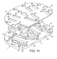
- the lower surface of the upper plate 51 as shown in Figure 11, is provided with recesses 60 to accommodate trunnions on the crossed arms (to be described). Trunnion location sockets 61 are also provided.
- the arrangement is repeated on the medial side of the plate to accommodate the operating apparatus for the medial upper element.
- the lower plate 50 is provided with openings 63, 64 to accommodate the lower ends of the crossed arms 7, 7a, on each side, and further parallel openings 65, 66 to accommodate the lower ends of the crossed arms 6 on each side.
- the trunnions 70 are located appropriately in the recesses 60 and location sockets 61 to provide fixed pivots in the sockets 61 and sliding pivots in the recesses 60 in a similar manner to the construction of the upper elements.
- Screw receiving holes 72 are provided in the lower plate 50 and screw threaded holes 73 in the upper plate 51 to receive screws 74, as shown in Figure 10, to hold the two plates together.
- Figure 9 shows the various crossed arms and one of the screw jacks in position and resting on the lower plate 50.
- the lateral crossed arms are shown in the lowered position and the medial crossed arms in a raised position.
- the upper elements and the upper plate 51 of the lower element are not shown.
- the invention provides a construction which enables the two upper elements to be operated independently utilising a reliable and strong operating mechanism which can be easily operated in the operating theatre and does not require any further apparatus apart from an allen key to operate the screw jacks.
- knee balance stability in flexion and extension can be accessed with the patella in place.
Landscapes
- Health & Medical Sciences (AREA)
- Life Sciences & Earth Sciences (AREA)
- Surgery (AREA)
- Molecular Biology (AREA)
- General Health & Medical Sciences (AREA)
- Biomedical Technology (AREA)
- Heart & Thoracic Surgery (AREA)
- Medical Informatics (AREA)
- Nuclear Medicine, Radiotherapy & Molecular Imaging (AREA)
- Animal Behavior & Ethology (AREA)
- Engineering & Computer Science (AREA)
- Public Health (AREA)
- Veterinary Medicine (AREA)
- Prostheses (AREA)
- Carriages For Children, Sleds, And Other Hand-Operated Vehicles (AREA)
- Orthopedics, Nursing, And Contraception (AREA)
- Acyclic And Carbocyclic Compounds In Medicinal Compositions (AREA)
- Organic Low-Molecular-Weight Compounds And Preparation Thereof (AREA)
Abstract
Description
- This invention relates to a knee distracter which can be used, for example, during the insertion of a prosthesis.
- When prostheses are to be implanted, or for other operations involving the knee, it is often necessary to space the tibia away from the femur and, moreover, it is desirable to be able to act on the condyles of the femur so that they can be displaced individually and to varying degrees.
-
WO 2004/078047 shows a knee distracter which allows the above operations to be carried out but which employs flexible control means using a system of cables or a pneumatic arrangement. - Such control means are difficult to actuate in the operating theatre and are often inaccurate.
- The present invention is intended to provide a knee distracter in which accurate and positive control of the parts can be achieved.
- According to the present invention a knee distracter comprises a lower element and two upper elements located above the lower element, operating means for moving each upper element independently to adjust its distance from the lower element and in which said operating means for each upper element comprises first and second crossed arms which are pivoted together at intermediate points in their lengths to provide a scissors action between them, a first end of a first arm being connected by a fixed pivot to the upper element and a second end of said first arm being connected by a sliding pivot to the lower element, a first end of the second arm being connected by a fixed pivot to the lower element and a second end of said second arm being connected by a sliding pivot to the upper element, and means for drawing the sliding pivot on one arm towards or away from the fixed pivot on the other arm to cause the distance between the upper and lower element to be adjusted.
- The use of the pivoted crossed arms provides accurate control of the spaced between the upper and lower elements.
- Preferably, the means for drawing the sliding pivot towards or away from the fixed pivot includes a screw jack.
- Each of the screw jacks may include a rotatable operating screw which is located substantially in the upper element and parallel with the upper surface thereof.
- The rotatable operating screw can act on a threaded nut which is pivoted to the sliding pivot of the first end of the second arm.
- Preferably, each upper element is provided with a pair of spaced apart first and second crossed arms, the axes and pivots of the first crossed arms being coaxial with the axes and pivots of the second crossed arms.
- With this arrangement the said screw jacks can be located between a pair of crossed arms.
- In a preferred construction each upper element comprises two parallel plates which locate between them the fixed pivot on the first arm and provide a slide to locate the sliding pivot on the second arm, and locate the screw jack.
- With this construction the lower element may also comprise two parallel plates which locate between them the fixed pivot on the second arm and provide a slide to locate the sliding pivot on the first arm.
- In all the above constructions the lower surface of the upper elements preferably lie in parallel engagement with the upper surface of the lower element when in a closed position.
- The axis of rotation of the screw jacks may be arranged to extend in a posterior/anterior direction.
- The invention can be performed in various ways and some embodiments will now be described by way of example and with reference to the accompanying drawings in which :
- Figure 1 is an isometric view of the knee distracter according to the present invention from the anterior side with one of the upper elements in the raised position and the other upper element in its lowest position;
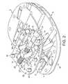
- Figure 2 is a similar view to that shown in Figure 1 with one upper element in the raised position but with its top plate removed to reveal the mounting arrangements;
- Figure 3 is a side elevation of the construction shown in Figures 1 and 2 from the lateral side with the medial upper element again in the raised position and the lateral upper element in its lowermost position and with the upper plates of both of the upper elements removed;
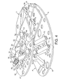
- Figure 4 is a similar view to Figures 1 and 3 with the upper plates of the medial and lateral upper elements removed and with the upper plate of the lower element also removed;
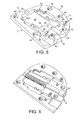
- Figure 5 is an isometric view of the lower surface of one of the upper elements from its anterior side;
- Figure 6 is a similar view to Figure 5 with one of the screw jack screws in place;
- Figure 7 is a similar view to Figure 6 but with part of the operating mechanism in the form of a threaded nut in place;
- Figure 8 is a view similar to that shown in Figure 7 but with the crossed arms in place and located by the lower plate of the element;
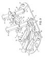
- Figure 9 is an isometric view from above and from the distal side of the lower plate of the lower element partly assembled with its two pairs of crossed arms, the crossed arms for the medial upper element being shown in the raised position and the crossed arms for the lateral upper element being in the lower position, the lateral screw jack is also shown;
- Figure 10 is an isometric view of the upper and lower plates of the lower element taken from the posterior side; and,
- Figure 11 is an isometric view from the posterior side of the two plates shown in Figure 10 but from beneath;
- As shown in Figure 1 the assembled distracter comprises a lower element 1 and two
upper elements 2 and 3. The anterior side of the device is indicated by reference numeral P, the medial side by reference numeral M and the lateral side by reference numeral L. The medial and lateralupper elements 2 and 3 are located above the lower element 1 and operating means 4 for moving each upper element independently to adjust its distance from the lower element 1 is provided. The operating means 4 for eachupper element 2 or 3 comprises first and second crossedarms intermediate points 8 in their lengths to provide a scissors action between them. Afirst end 9 of thefirst arm 6 is connected by a fixed pivot 10 (not shown in Figure 1) to the upper element 2 and asecond end 5 of thisfirst arm 6 is connected by a sliding pivot (not shown in Figure 1) to the lower element 1. Afirst end 11 of thesecond arm 7 is connected by a fixed pivot (not shown in Figure 1) to the lower element 1 and asecond end 12 of saidsecond arm 7 being connected by sliding pivot (not shown in Figure 1) to the upper element 2. Means are provided for drawing the sliding pivot on one arm towards or away from the fixed pivot on the other arm to cause the distance between the upper and lower elements to be adjusted. In the construction being described this is achieved by means of ascrew jack 15 which comprises arotatable operating screw 16, the anterior end of which is provided with a head to received an operating allen key. The threadedpart 17 of thescrew 16 carries a threadednut 18 which is pivoted to the sliding pivot on theend 12 of thesecond arm 7 so that rotation of thescrew 16 causes theend 12 of thesecond arm 7 to approach the fixed pivot on thefirst end 9 of theother arm 6 or moves them apart thus raising and lowering the upper element in relation to the lower element. - In the embodiment described each of the
upper elements 2 and 3 is provided with a pair of crossed arms, the second of the crossed arms as shown in Figure 1 being indicated byreference numerals arms arms - The
second arms screw jack 15, thearms - The
rotatable operating screw 16 is located in the upper element 2 substantially parallel with theupper surface 20 thereof and the screw is located between the pair ofcrossed arms - The same mechanism is also provided in the lateral
upper plate 3 and on the lateral side of the lower element 1. - It will be appreciated that each of the
upper elements 2 or 3 can be operated independently of the other to provide the desired spacing when separating the bones of the knee. - Each
upper element 2 or 3 is formed from upper and lower plates which are shown in Figures 2, 5, 6 and 7 and when assembled in Figure 8 and the lower element 1 is also made up from upper and lower plates which are shown in Figures 9, 10 and 11. - Each of the
lower plates 19 on theupper elements 2 and 3 is substantially flat and has twoopenings ends arms - The
ends arms trunnions 23 which, when the apparatus is assembled, rest against the upper surface of thelower plate 19 which retains them in place further. Anopening 24 is provided in the plate to accommodate theends arms nut 18 of thescrew jack 15. Each of theends trunnions 25 which extend on their outer ends over part of theplate 19 on each side, the other ends of the trunnions being housed in thenut 18 to provide a pivotal joint. The posterior side of theplate 19 is provided with a downwardly extendingprojection 27 to form a split bearing to accommodate theend 28 of thescrew 16.Screw 16 also has alocation flange 29 which bears against one side of the opening 24 and which co-operates with the head of the screw to locate it axially in place in theplate 19. - The construction described above is the same for both upper elements.
- The various parts are held in place on each of the upper elements by an
upper plate 31, the lower surface of which is shown Figures 5, 6 and 7. Eachupper plate 31 has acentral opening 32 to accommodate theupper ends crossed arms screw jack mechanism 15. When theupper plate 31 is located in place thetrunnions 25 on theends 12a of the arms are located in opensided grooves - The
nut 18 which is located between the two arms is prevented from rotating on thescrew 16 and theend 28 of the screw is located in abearing recess 34. The anterior end of the screw is located in afurther recess 35 and is free to rotate therein. Theend 36 of theopening 32 engages theflange 29 on thescrew 16 and the screw head is located in arecess 37 in the anterior edge of the plate. - Two
further openings ends arms trunnions 23 are located in bearing recesses 4 which, when the plates are assembled, act to provide fixed pivots for theends 9 of thearms 6. -
Upper plate 34 is connected tolower plate 19 by set screws indicated byreference numeral 40 in Figure 2. These setscrews 40 are not shown in Figure 4 but the holes to receive them are indicated byreference numeral 41. Theset screws 40 are screwed into threadedopenings 43 which are shown in Figures 5, 6 and 7. - Figure 6 is a view similar to Figure 5 showing the
set screw 16 in position and Figure 7 shows thescrew 16 together with itsnut 18 located in theopening 24. Thetrunnions 25 at theends arms nut 18 and against theplate 31 or being held rigidly in thenut 18 and locating against the ends of thearms - Figure 8 shows the
upper plate 34 connected to the lower plate with thecrossed arms screw 16. In this Figure the pins which provide thepivot 8 and trunnions which connect to the lower plate 1 (to be described hereunder) have not yet been inserted and thescrews 40 have not been entered into thescrew holes 41 or screw threadedopenings 43. - The construction of the lower element 1 includes a substantially flat lower plate 50 (as shown in Figure 10) and a co-operating
upper plate 51. - The
upper plate 51 hastroughs screw 16 when theupper elements 2 and 3 are in their closed and lowest position. - The
upper plate 51 also has spacedparallel openings arms parallel openings arms upper plate 51, as shown in Figure 11, is provided withrecesses 60 to accommodate trunnions on the crossed arms (to be described).Trunnion location sockets 61 are also provided. - The arrangement is repeated on the medial side of the plate to accommodate the operating apparatus for the medial upper element.
- The
lower plate 50 is provided withopenings arms parallel openings arms 6 on each side. - As is clear from Figure 4 the
lower end 5 of the crossedarm 6 and lower ends 11 of thearms 7carry projecting trunnions 7 and the trunnions extending between thearms single pin 71. - The
trunnions 70 are located appropriately in therecesses 60 andlocation sockets 61 to provide fixed pivots in thesockets 61 and sliding pivots in therecesses 60 in a similar manner to the construction of the upper elements. - Screw receiving
holes 72 are provided in thelower plate 50 and screw threadedholes 73 in theupper plate 51 to receivescrews 74, as shown in Figure 10, to hold the two plates together. - Figure 9 shows the various crossed arms and one of the screw jacks in position and resting on the
lower plate 50. The lateral crossed arms are shown in the lowered position and the medial crossed arms in a raised position. In this Figure the upper elements and theupper plate 51 of the lower element are not shown. The invention provides a construction which enables the two upper elements to be operated independently utilising a reliable and strong operating mechanism which can be easily operated in the operating theatre and does not require any further apparatus apart from an allen key to operate the screw jacks. - Due to the construction of the device according to the present invention knee balance stability in flexion and extension can be accessed with the patella in place.
Claims (10)
- A knee distracter comprising a lower element and two upper elements located above the lower element, operating means for moving each upper element independently to adjust its distance from the lower element and in which said operating means for each upper element comprises first and second crossed arms which are pivoted together at intermediate points in their lengths to provide a scissors action between them, a first end of a first arm being connected by a fixed pivot to an upper element and a second end of said first arm being connected by a sliding pivot to the lower element, a first end of the second arm being connected by a fixed pivot to the lower element and a second end of said second arm being connected by a sliding pivot to the upper element, and means for drawing the sliding pivot on one arm towards or away from the fixed pivot on the other arm to cause the distance between the upper and lower element to be adjusted.
- A knee distracter as claimed in claim 1 in which the means for drawing the sliding pivot towards or away from the fixed pivot includes a screw jack.
- A knee distracter as claimed in claim 2 in which each of the screw jacks may includes a rotatable operating screw which is located substantially in the upper element and parallel with the upper surface thereof.
- A knee distracter as claimed in claim 3 in which the rotatable operating screw acts on a threaded nut which is pivoted to the sliding pivot of the first end of the second arm.
- A knee distracter as claimed in any one of the preceding claims in which each upper element is provided with a pair of spaced apart first and second crossed arms, the axes and pivots of the first crossed arms being coaxial with the axes and pivots of the second crossed arms.
- A knee distracter as claimed in claim 5, when dependent on any one of claims 2, 3 or 4, in which said screw jacks can be located between a pair of crossed arms.
- A knee distracter as claimed in any one of preceding claims 1 to 6 in which each upper element comprises two parallel plates which locate between them the fixed pivot on the first arm and provide a slide to locate the sliding pivot on the second arm, and locate the screw jack.
- A knee distracter as claimed in claim 7 in which the lower element also comprises two parallel plates which locate between them the fixed pivot on the second arm and provide a slide to locate the sliding pivot on the first arm.
- A knee distracter as claimed in claim 7 or claim 8 in which the lower surface of the upper elements lie in parallel engagement with the upper surface of the lower element when in a closed position.
- A knee distracter as claimed in an one of preceding claims 2 to 9 in which axis of rotation of the screw jacks may be arranged to extend in a posterior/anterior direction.
Applications Claiming Priority (1)
| Application Number | Priority Date | Filing Date | Title |
|---|---|---|---|
| GBGB0621341.7A GB0621341D0 (en) | 2006-10-26 | 2006-10-26 | Knee distractor |
Publications (3)
| Publication Number | Publication Date |
|---|---|
| EP1915951A2 true EP1915951A2 (en) | 2008-04-30 |
| EP1915951A3 EP1915951A3 (en) | 2009-10-07 |
| EP1915951B1 EP1915951B1 (en) | 2011-06-29 |
Family
ID=37546044
Family Applications (1)
| Application Number | Title | Priority Date | Filing Date |
|---|---|---|---|
| EP07254164A Not-in-force EP1915951B1 (en) | 2006-10-26 | 2007-10-19 | Knee distractor |
Country Status (3)
| Country | Link |
|---|---|
| EP (1) | EP1915951B1 (en) |
| AT (1) | ATE514381T1 (en) |
| GB (1) | GB0621341D0 (en) |
Cited By (14)
| Publication number | Priority date | Publication date | Assignee | Title |
|---|---|---|---|---|
| WO2011012533A1 (en) | 2009-07-28 | 2011-02-03 | Italorthopedics S.A.S. Di Intermediazioni Commerciali S.R.L. | Distractor device for joints |
| GB2479899A (en) * | 2010-04-28 | 2011-11-02 | Biomet Uk Ltd | Alignment tool for use in joint replacement |
| JP2013202415A (en) * | 2012-03-29 | 2013-10-07 | Depuy Synthes Products Llc | Orthopaedic surgical instrument for knee surgery |
| US8551023B2 (en) | 2009-03-31 | 2013-10-08 | Depuy (Ireland) | Device and method for determining force of a knee joint |
| US8556830B2 (en) | 2009-03-31 | 2013-10-15 | Depuy | Device and method for displaying joint force data |
| US8597210B2 (en) | 2009-03-31 | 2013-12-03 | Depuy (Ireland) | System and method for displaying joint force data |
| US8721568B2 (en) | 2009-03-31 | 2014-05-13 | Depuy (Ireland) | Method for performing an orthopaedic surgical procedure |
| US8740817B2 (en) | 2009-03-31 | 2014-06-03 | Depuy (Ireland) | Device and method for determining forces of a patient's joint |
| CN106236289A (en) * | 2016-07-28 | 2016-12-21 | 上海市第十人民医院 | Femoral rotation osteotomy automatic backlash static organ in a kind of total knee arthroplasty |
| WO2017195046A3 (en) * | 2016-04-28 | 2018-01-04 | Medfit Beratungs-Und Beteiligungsges.M.B.H | Dynamic ligament balancing system |
| WO2019115744A1 (en) * | 2017-12-15 | 2019-06-20 | Depuy Ireland Unlimited Company | A knee balancing instrument |
| US11051955B2 (en) | 2012-03-31 | 2021-07-06 | DePuy Synthes Products, Inc. | System and method for validating an orthopaedic surgical plan |
| WO2023044095A3 (en) * | 2021-09-20 | 2023-05-04 | Little Engine, LLC | Tensioner-balancer for knee joint |
| EP4164483A4 (en) * | 2020-06-16 | 2024-07-03 | Exactech, Inc. | Mechanical ligament balancing devices |
Families Citing this family (5)
| Publication number | Priority date | Publication date | Assignee | Title |
|---|---|---|---|---|
| US8197489B2 (en) | 2008-06-27 | 2012-06-12 | Depuy Products, Inc. | Knee ligament balancer |
| GB201115411D0 (en) | 2011-09-07 | 2011-10-19 | Depuy Ireland | Surgical instrument |
| US10070973B2 (en) | 2012-03-31 | 2018-09-11 | Depuy Ireland Unlimited Company | Orthopaedic sensor module and system for determining joint forces of a patient's knee joint |
| US10206792B2 (en) | 2012-03-31 | 2019-02-19 | Depuy Ireland Unlimited Company | Orthopaedic surgical system for determining joint forces of a patients knee joint |
| US9545459B2 (en) | 2012-03-31 | 2017-01-17 | Depuy Ireland Unlimited Company | Container for surgical instruments and system including same |
Citations (2)
| Publication number | Priority date | Publication date | Assignee | Title |
|---|---|---|---|---|
| WO2004078047A1 (en) | 2003-02-27 | 2004-09-16 | Universite Joseph Fourier | Knee distractor |
| DE102005049851A1 (en) | 2005-10-18 | 2007-04-26 | Plus Orthopedics Ag | StrapsTie device |
Family Cites Families (1)
| Publication number | Priority date | Publication date | Assignee | Title |
|---|---|---|---|---|
| SE400922B (en) * | 1971-11-06 | 1978-04-17 | Fujikoshi Kk | GOODS HANDLING DEVICE |
-
2006
- 2006-10-26 GB GBGB0621341.7A patent/GB0621341D0/en not_active Ceased
-
2007
- 2007-10-19 AT AT07254164T patent/ATE514381T1/en not_active IP Right Cessation
- 2007-10-19 EP EP07254164A patent/EP1915951B1/en not_active Not-in-force
Patent Citations (2)
| Publication number | Priority date | Publication date | Assignee | Title |
|---|---|---|---|---|
| WO2004078047A1 (en) | 2003-02-27 | 2004-09-16 | Universite Joseph Fourier | Knee distractor |
| DE102005049851A1 (en) | 2005-10-18 | 2007-04-26 | Plus Orthopedics Ag | StrapsTie device |
Cited By (25)
| Publication number | Priority date | Publication date | Assignee | Title |
|---|---|---|---|---|
| US8721568B2 (en) | 2009-03-31 | 2014-05-13 | Depuy (Ireland) | Method for performing an orthopaedic surgical procedure |
| US8740817B2 (en) | 2009-03-31 | 2014-06-03 | Depuy (Ireland) | Device and method for determining forces of a patient's joint |
| US8597210B2 (en) | 2009-03-31 | 2013-12-03 | Depuy (Ireland) | System and method for displaying joint force data |
| US8551023B2 (en) | 2009-03-31 | 2013-10-08 | Depuy (Ireland) | Device and method for determining force of a knee joint |
| US8556830B2 (en) | 2009-03-31 | 2013-10-15 | Depuy | Device and method for displaying joint force data |
| WO2011012533A1 (en) | 2009-07-28 | 2011-02-03 | Italorthopedics S.A.S. Di Intermediazioni Commerciali S.R.L. | Distractor device for joints |
| GB2479899A (en) * | 2010-04-28 | 2011-11-02 | Biomet Uk Ltd | Alignment tool for use in joint replacement |
| JP2013202415A (en) * | 2012-03-29 | 2013-10-07 | Depuy Synthes Products Llc | Orthopaedic surgical instrument for knee surgery |
| US12161314B2 (en) * | 2012-03-29 | 2024-12-10 | Depuy Ireland Unlimited Company | Orthopedic surgical instrument for knee surgery |
| US10485530B2 (en) | 2012-03-29 | 2019-11-26 | Depuy Ireland Unlimited Company | Orthopedic surgical instrument for knee surgery |
| US9381011B2 (en) | 2012-03-29 | 2016-07-05 | Depuy (Ireland) | Orthopedic surgical instrument for knee surgery |
| EP2901941A1 (en) * | 2012-03-29 | 2015-08-05 | DePuy (Ireland) | Orthopaedic surgical instrument for knee surgery |
| JP2017164592A (en) * | 2012-03-29 | 2017-09-21 | デピュイ・シンセス・プロダクツ・インコーポレイテッド | Orthopedic surgical instruments for knee surgery |
| US20230200796A1 (en) * | 2012-03-29 | 2023-06-29 | Depuy Ireland Unlimited Company | Orthopedic surgical instrument for knee surgery |
| US11589857B2 (en) | 2012-03-29 | 2023-02-28 | Depuy Ireland Unlimited Company | Orthopedic surgical instrument for knee surgery |
| US11051955B2 (en) | 2012-03-31 | 2021-07-06 | DePuy Synthes Products, Inc. | System and method for validating an orthopaedic surgical plan |
| JP2019519268A (en) * | 2016-04-28 | 2019-07-11 | メドフィット ベラタングス−ウンド ベタイリグンスゲス.エム.ビー.エイチ | Dynamic ligament balancing system |
| US10722385B2 (en) | 2016-04-28 | 2020-07-28 | medFit Beratungs-und Beteilgungsges.m.B.H. | Dynamic ligament balancing system |
| KR20190004723A (en) * | 2016-04-28 | 2019-01-14 | 메드핏 베라퉁스-운트 베타일리궁스게스.엠.베.하 | Dynamic ligament balancing system |
| WO2017195046A3 (en) * | 2016-04-28 | 2018-01-04 | Medfit Beratungs-Und Beteiligungsges.M.B.H | Dynamic ligament balancing system |
| CN106236289A (en) * | 2016-07-28 | 2016-12-21 | 上海市第十人民医院 | Femoral rotation osteotomy automatic backlash static organ in a kind of total knee arthroplasty |
| WO2019115744A1 (en) * | 2017-12-15 | 2019-06-20 | Depuy Ireland Unlimited Company | A knee balancing instrument |
| US11678894B2 (en) | 2017-12-15 | 2023-06-20 | Jonathan P. Cabot | Knee balancing instrument |
| EP4164483A4 (en) * | 2020-06-16 | 2024-07-03 | Exactech, Inc. | Mechanical ligament balancing devices |
| WO2023044095A3 (en) * | 2021-09-20 | 2023-05-04 | Little Engine, LLC | Tensioner-balancer for knee joint |
Also Published As
| Publication number | Publication date |
|---|---|
| EP1915951A3 (en) | 2009-10-07 |
| ATE514381T1 (en) | 2011-07-15 |
| GB0621341D0 (en) | 2006-12-06 |
| EP1915951B1 (en) | 2011-06-29 |
Similar Documents
| Publication | Publication Date | Title |
|---|---|---|
| EP1915951B1 (en) | Knee distractor | |
| JP5800253B2 (en) | Alignment tool | |
| US20240041445A1 (en) | Soft Tissue Retractor | |
| US12161314B2 (en) | Orthopedic surgical instrument for knee surgery | |
| US8435304B2 (en) | Adjustable knee tibial trial insert | |
| EP2138107B1 (en) | Ligament balancer | |
| ES2963827T3 (en) | An arrangement for use in preparing the proximal surface of the tibia for the tibia component of a knee joint prosthesis | |
| BR112018069074B1 (en) | COLUMN CAGE | |
| EP2442736B1 (en) | Midline referencing femoral sizing caliper | |
| AU2012342759B2 (en) | Device for defining a cutting plane for bone resection | |
| CN103002818B (en) | A surgical instrument | |
| EP2158879A1 (en) | Trial Prosthesis for total knee arthroplasty | |
| RU2607957C2 (en) | Equipment for placement of joint prosthesis, particularly knee prosthesis | |
| CA2209498A1 (en) | Trial knee prosthesis and bone preparation system | |
| CN109152580A (en) | Prepare the orthopaedic surgical instrument system of patient femur for surgery | |
| CN214712687U (en) | Single-side lead screw adjusting type bone cutting device for femoral condyle | |
| CN112754594A (en) | Single-side lead screw adjusting type bone cutting device for femoral condyle | |
| DE8909287U1 (en) | Instrument for aligning a cutting surface to facilitate the resection of a tibial surface |
Legal Events
| Date | Code | Title | Description |
|---|---|---|---|
| PUAI | Public reference made under article 153(3) epc to a published international application that has entered the european phase |
Free format text: ORIGINAL CODE: 0009012 |
|
| AK | Designated contracting states |
Kind code of ref document: A2 Designated state(s): AT BE BG CH CY CZ DE DK EE ES FI FR GB GR HU IE IS IT LI LT LU LV MC MT NL PL PT RO SE SI SK TR |
|
| AX | Request for extension of the european patent |
Extension state: AL BA HR MK RS |
|
| PUAL | Search report despatched |
Free format text: ORIGINAL CODE: 0009013 |
|
| AK | Designated contracting states |
Kind code of ref document: A3 Designated state(s): AT BE BG CH CY CZ DE DK EE ES FI FR GB GR HU IE IS IT LI LT LU LV MC MT NL PL PT RO SE SI SK TR |
|
| AX | Request for extension of the european patent |
Extension state: AL BA HR MK RS |
|
| 17P | Request for examination filed |
Effective date: 20100217 |
|
| 17Q | First examination report despatched |
Effective date: 20100318 |
|
| AKX | Designation fees paid |
Designated state(s): AT BE BG CH CY CZ DE DK EE ES FI FR GB GR HU IE IS IT LI LT LU LV MC MT NL PL PT RO SE SI SK TR |
|
| GRAP | Despatch of communication of intention to grant a patent |
Free format text: ORIGINAL CODE: EPIDOSNIGR1 |
|
| GRAS | Grant fee paid |
Free format text: ORIGINAL CODE: EPIDOSNIGR3 |
|
| GRAA | (expected) grant |
Free format text: ORIGINAL CODE: 0009210 |
|
| AK | Designated contracting states |
Kind code of ref document: B1 Designated state(s): AT BE BG CH CY CZ DE DK EE ES FI FR GB GR HU IE IS IT LI LT LU LV MC MT NL PL PT RO SE SI SK TR |
|
| REG | Reference to a national code |
Ref country code: GB Ref legal event code: FG4D |
|
| REG | Reference to a national code |
Ref country code: CH Ref legal event code: EP |
|
| REG | Reference to a national code |
Ref country code: IE Ref legal event code: FG4D |
|
| REG | Reference to a national code |
Ref country code: DE Ref legal event code: R096 Ref document number: 602007015492 Country of ref document: DE Effective date: 20110825 |
|
| REG | Reference to a national code |
Ref country code: NL Ref legal event code: VDEP Effective date: 20110629 |
|
| PG25 | Lapsed in a contracting state [announced via postgrant information from national office to epo] |
Ref country code: LT Free format text: LAPSE BECAUSE OF FAILURE TO SUBMIT A TRANSLATION OF THE DESCRIPTION OR TO PAY THE FEE WITHIN THE PRESCRIBED TIME-LIMIT Effective date: 20110629 Ref country code: SE Free format text: LAPSE BECAUSE OF FAILURE TO SUBMIT A TRANSLATION OF THE DESCRIPTION OR TO PAY THE FEE WITHIN THE PRESCRIBED TIME-LIMIT Effective date: 20110629 |
|
| PG25 | Lapsed in a contracting state [announced via postgrant information from national office to epo] |
Ref country code: LV Free format text: LAPSE BECAUSE OF FAILURE TO SUBMIT A TRANSLATION OF THE DESCRIPTION OR TO PAY THE FEE WITHIN THE PRESCRIBED TIME-LIMIT Effective date: 20110629 Ref country code: FI Free format text: LAPSE BECAUSE OF FAILURE TO SUBMIT A TRANSLATION OF THE DESCRIPTION OR TO PAY THE FEE WITHIN THE PRESCRIBED TIME-LIMIT Effective date: 20110629 Ref country code: GR Free format text: LAPSE BECAUSE OF FAILURE TO SUBMIT A TRANSLATION OF THE DESCRIPTION OR TO PAY THE FEE WITHIN THE PRESCRIBED TIME-LIMIT Effective date: 20110930 Ref country code: SI Free format text: LAPSE BECAUSE OF FAILURE TO SUBMIT A TRANSLATION OF THE DESCRIPTION OR TO PAY THE FEE WITHIN THE PRESCRIBED TIME-LIMIT Effective date: 20110629 Ref country code: AT Free format text: LAPSE BECAUSE OF FAILURE TO SUBMIT A TRANSLATION OF THE DESCRIPTION OR TO PAY THE FEE WITHIN THE PRESCRIBED TIME-LIMIT Effective date: 20110629 |
|
| PG25 | Lapsed in a contracting state [announced via postgrant information from national office to epo] |
Ref country code: BE Free format text: LAPSE BECAUSE OF FAILURE TO SUBMIT A TRANSLATION OF THE DESCRIPTION OR TO PAY THE FEE WITHIN THE PRESCRIBED TIME-LIMIT Effective date: 20110629 |
|
| PG25 | Lapsed in a contracting state [announced via postgrant information from national office to epo] |
Ref country code: PT Free format text: LAPSE BECAUSE OF FAILURE TO SUBMIT A TRANSLATION OF THE DESCRIPTION OR TO PAY THE FEE WITHIN THE PRESCRIBED TIME-LIMIT Effective date: 20111031 Ref country code: CZ Free format text: LAPSE BECAUSE OF FAILURE TO SUBMIT A TRANSLATION OF THE DESCRIPTION OR TO PAY THE FEE WITHIN THE PRESCRIBED TIME-LIMIT Effective date: 20110629 Ref country code: EE Free format text: LAPSE BECAUSE OF FAILURE TO SUBMIT A TRANSLATION OF THE DESCRIPTION OR TO PAY THE FEE WITHIN THE PRESCRIBED TIME-LIMIT Effective date: 20110629 Ref country code: NL Free format text: LAPSE BECAUSE OF FAILURE TO SUBMIT A TRANSLATION OF THE DESCRIPTION OR TO PAY THE FEE WITHIN THE PRESCRIBED TIME-LIMIT Effective date: 20110629 Ref country code: IS Free format text: LAPSE BECAUSE OF FAILURE TO SUBMIT A TRANSLATION OF THE DESCRIPTION OR TO PAY THE FEE WITHIN THE PRESCRIBED TIME-LIMIT Effective date: 20111029 |
|
| PG25 | Lapsed in a contracting state [announced via postgrant information from national office to epo] |
Ref country code: RO Free format text: LAPSE BECAUSE OF FAILURE TO SUBMIT A TRANSLATION OF THE DESCRIPTION OR TO PAY THE FEE WITHIN THE PRESCRIBED TIME-LIMIT Effective date: 20110629 Ref country code: CY Free format text: LAPSE BECAUSE OF FAILURE TO SUBMIT A TRANSLATION OF THE DESCRIPTION OR TO PAY THE FEE WITHIN THE PRESCRIBED TIME-LIMIT Effective date: 20110629 Ref country code: SK Free format text: LAPSE BECAUSE OF FAILURE TO SUBMIT A TRANSLATION OF THE DESCRIPTION OR TO PAY THE FEE WITHIN THE PRESCRIBED TIME-LIMIT Effective date: 20110629 Ref country code: PL Free format text: LAPSE BECAUSE OF FAILURE TO SUBMIT A TRANSLATION OF THE DESCRIPTION OR TO PAY THE FEE WITHIN THE PRESCRIBED TIME-LIMIT Effective date: 20110629 |
|
| PLBE | No opposition filed within time limit |
Free format text: ORIGINAL CODE: 0009261 |
|
| STAA | Information on the status of an ep patent application or granted ep patent |
Free format text: STATUS: NO OPPOSITION FILED WITHIN TIME LIMIT |
|
| PG25 | Lapsed in a contracting state [announced via postgrant information from national office to epo] |
Ref country code: IT Free format text: LAPSE BECAUSE OF FAILURE TO SUBMIT A TRANSLATION OF THE DESCRIPTION OR TO PAY THE FEE WITHIN THE PRESCRIBED TIME-LIMIT Effective date: 20110629 Ref country code: MC Free format text: LAPSE BECAUSE OF NON-PAYMENT OF DUE FEES Effective date: 20111031 |
|
| REG | Reference to a national code |
Ref country code: CH Ref legal event code: PL |
|
| 26N | No opposition filed |
Effective date: 20120330 |
|
| PG25 | Lapsed in a contracting state [announced via postgrant information from national office to epo] |
Ref country code: DK Free format text: LAPSE BECAUSE OF FAILURE TO SUBMIT A TRANSLATION OF THE DESCRIPTION OR TO PAY THE FEE WITHIN THE PRESCRIBED TIME-LIMIT Effective date: 20110629 |
|
| PG25 | Lapsed in a contracting state [announced via postgrant information from national office to epo] |
Ref country code: LI Free format text: LAPSE BECAUSE OF NON-PAYMENT OF DUE FEES Effective date: 20111031 Ref country code: CH Free format text: LAPSE BECAUSE OF NON-PAYMENT OF DUE FEES Effective date: 20111031 |
|
| REG | Reference to a national code |
Ref country code: IE Ref legal event code: MM4A |
|
| REG | Reference to a national code |
Ref country code: DE Ref legal event code: R097 Ref document number: 602007015492 Country of ref document: DE Effective date: 20120330 |
|
| PG25 | Lapsed in a contracting state [announced via postgrant information from national office to epo] |
Ref country code: IE Free format text: LAPSE BECAUSE OF NON-PAYMENT OF DUE FEES Effective date: 20111019 |
|
| PG25 | Lapsed in a contracting state [announced via postgrant information from national office to epo] |
Ref country code: MT Free format text: LAPSE BECAUSE OF FAILURE TO SUBMIT A TRANSLATION OF THE DESCRIPTION OR TO PAY THE FEE WITHIN THE PRESCRIBED TIME-LIMIT Effective date: 20110629 |
|
| PG25 | Lapsed in a contracting state [announced via postgrant information from national office to epo] |
Ref country code: ES Free format text: LAPSE BECAUSE OF FAILURE TO SUBMIT A TRANSLATION OF THE DESCRIPTION OR TO PAY THE FEE WITHIN THE PRESCRIBED TIME-LIMIT Effective date: 20111010 |
|
| PG25 | Lapsed in a contracting state [announced via postgrant information from national office to epo] |
Ref country code: LU Free format text: LAPSE BECAUSE OF NON-PAYMENT OF DUE FEES Effective date: 20111019 |
|
| PG25 | Lapsed in a contracting state [announced via postgrant information from national office to epo] |
Ref country code: BG Free format text: LAPSE BECAUSE OF FAILURE TO SUBMIT A TRANSLATION OF THE DESCRIPTION OR TO PAY THE FEE WITHIN THE PRESCRIBED TIME-LIMIT Effective date: 20110929 |
|
| PG25 | Lapsed in a contracting state [announced via postgrant information from national office to epo] |
Ref country code: TR Free format text: LAPSE BECAUSE OF FAILURE TO SUBMIT A TRANSLATION OF THE DESCRIPTION OR TO PAY THE FEE WITHIN THE PRESCRIBED TIME-LIMIT Effective date: 20110629 |
|
| PG25 | Lapsed in a contracting state [announced via postgrant information from national office to epo] |
Ref country code: HU Free format text: LAPSE BECAUSE OF FAILURE TO SUBMIT A TRANSLATION OF THE DESCRIPTION OR TO PAY THE FEE WITHIN THE PRESCRIBED TIME-LIMIT Effective date: 20110629 |
|
| REG | Reference to a national code |
Ref country code: FR Ref legal event code: PLFP Year of fee payment: 10 |
|
| PGFP | Annual fee paid to national office [announced via postgrant information from national office to epo] |
Ref country code: FR Payment date: 20160919 Year of fee payment: 10 |
|
| PGFP | Annual fee paid to national office [announced via postgrant information from national office to epo] |
Ref country code: DE Payment date: 20161011 Year of fee payment: 10 Ref country code: GB Payment date: 20161019 Year of fee payment: 10 |
|
| REG | Reference to a national code |
Ref country code: DE Ref legal event code: R119 Ref document number: 602007015492 Country of ref document: DE |
|
| GBPC | Gb: european patent ceased through non-payment of renewal fee |
Effective date: 20171019 |
|
| REG | Reference to a national code |
Ref country code: FR Ref legal event code: ST Effective date: 20180629 |
|
| PG25 | Lapsed in a contracting state [announced via postgrant information from national office to epo] |
Ref country code: DE Free format text: LAPSE BECAUSE OF NON-PAYMENT OF DUE FEES Effective date: 20180501 Ref country code: GB Free format text: LAPSE BECAUSE OF NON-PAYMENT OF DUE FEES Effective date: 20171019 |
|
| PG25 | Lapsed in a contracting state [announced via postgrant information from national office to epo] |
Ref country code: FR Free format text: LAPSE BECAUSE OF NON-PAYMENT OF DUE FEES Effective date: 20171031 |