EP1915528B1 - Free floating wave energy converter - Google Patents
Free floating wave energy converter Download PDFInfo
- Publication number
- EP1915528B1 EP1915528B1 EP06780553A EP06780553A EP1915528B1 EP 1915528 B1 EP1915528 B1 EP 1915528B1 EP 06780553 A EP06780553 A EP 06780553A EP 06780553 A EP06780553 A EP 06780553A EP 1915528 B1 EP1915528 B1 EP 1915528B1
- Authority
- EP
- European Patent Office
- Prior art keywords
- water
- wave energy
- energy converter
- inlet
- converter according
- Prior art date
- Legal status (The legal status is an assumption and is not a legal conclusion. Google has not performed a legal analysis and makes no representation as to the accuracy of the status listed.)
- Revoked
Links
Images


Classifications
-
- F—MECHANICAL ENGINEERING; LIGHTING; HEATING; WEAPONS; BLASTING
- F03—MACHINES OR ENGINES FOR LIQUIDS; WIND, SPRING, OR WEIGHT MOTORS; PRODUCING MECHANICAL POWER OR A REACTIVE PROPULSIVE THRUST, NOT OTHERWISE PROVIDED FOR
- F03B—MACHINES OR ENGINES FOR LIQUIDS
- F03B13/00—Adaptations of machines or engines for special use; Combinations of machines or engines with driving or driven apparatus; Power stations or aggregates
- F03B13/12—Adaptations of machines or engines for special use; Combinations of machines or engines with driving or driven apparatus; Power stations or aggregates characterised by using wave or tide energy
- F03B13/14—Adaptations of machines or engines for special use; Combinations of machines or engines with driving or driven apparatus; Power stations or aggregates characterised by using wave or tide energy using wave energy
- F03B13/22—Adaptations of machines or engines for special use; Combinations of machines or engines with driving or driven apparatus; Power stations or aggregates characterised by using wave or tide energy using wave energy using the flow of water resulting from wave movements to drive a motor or turbine
-
- F—MECHANICAL ENGINEERING; LIGHTING; HEATING; WEAPONS; BLASTING
- F03—MACHINES OR ENGINES FOR LIQUIDS; WIND, SPRING, OR WEIGHT MOTORS; PRODUCING MECHANICAL POWER OR A REACTIVE PROPULSIVE THRUST, NOT OTHERWISE PROVIDED FOR
- F03B—MACHINES OR ENGINES FOR LIQUIDS
- F03B13/00—Adaptations of machines or engines for special use; Combinations of machines or engines with driving or driven apparatus; Power stations or aggregates
- F03B13/12—Adaptations of machines or engines for special use; Combinations of machines or engines with driving or driven apparatus; Power stations or aggregates characterised by using wave or tide energy
- F03B13/14—Adaptations of machines or engines for special use; Combinations of machines or engines with driving or driven apparatus; Power stations or aggregates characterised by using wave or tide energy using wave energy
- F03B13/141—Adaptations of machines or engines for special use; Combinations of machines or engines with driving or driven apparatus; Power stations or aggregates characterised by using wave or tide energy using wave energy with a static energy collector
- F03B13/144—Adaptations of machines or engines for special use; Combinations of machines or engines with driving or driven apparatus; Power stations or aggregates characterised by using wave or tide energy using wave energy with a static energy collector which lifts water above sea level
- F03B13/147—Adaptations of machines or engines for special use; Combinations of machines or engines with driving or driven apparatus; Power stations or aggregates characterised by using wave or tide energy using wave energy with a static energy collector which lifts water above sea level for later use
-
- Y—GENERAL TAGGING OF NEW TECHNOLOGICAL DEVELOPMENTS; GENERAL TAGGING OF CROSS-SECTIONAL TECHNOLOGIES SPANNING OVER SEVERAL SECTIONS OF THE IPC; TECHNICAL SUBJECTS COVERED BY FORMER USPC CROSS-REFERENCE ART COLLECTIONS [XRACs] AND DIGESTS
- Y02—TECHNOLOGIES OR APPLICATIONS FOR MITIGATION OR ADAPTATION AGAINST CLIMATE CHANGE
- Y02E—REDUCTION OF GREENHOUSE GAS [GHG] EMISSIONS, RELATED TO ENERGY GENERATION, TRANSMISSION OR DISTRIBUTION
- Y02E10/00—Energy generation through renewable energy sources
- Y02E10/30—Energy from the sea, e.g. using wave energy or salinity gradient
Definitions
- This invention relates to ocean energy and more particularly wave energy converters (WEC).
- WEC wave energy converters
- a 'Flexible Pipe' floats on the surface of water and adapts to the waveform. Air and water are trapped in the pipe and segregated - due to gravity, into discrete segments or "Slugs" in the crests and troughs, respectively. The segments get pushed by the waves as they propagate from one end of it to the other. Thus, energy is extracted by virtue of the propagation of waves. The segments can flow even against pressure, if applied at the Outlet. The total pressure in a pipe will be the function of the cumulative differential pressure of all the water segments in that pipe - less losses.”
- the Wave Energy Converters has been known for many years, it was only during the last decade and a half or so that serious efforts were initiated towards exploiting it commercially.
- Several ocean wave energy conversion devices have since been developed, but only a few matured to full-scale trial stage, but none yet implemented fully on a commercial scale.
- the main disadvantage of the wave power is the uneconomical cost of extracting wave energy.
- the World Energy Council estimates that 2TW of energy could be harvested from the world's oceans, the equivalent of twice the world's electricity production. However, since waves are neither steady nor concentrated enough it has not yet been possible to extract and supply wave energy viably.
- the major problem with designing wave energy converters has been in handling the vast range of power variations in the ocean waves, from approximately average of 50 kW/m, peaking to 10 MW/m (a 1:200 ratio).
- WEC wave energy converters
- shoreline devices also called “tapered channel” or “tapchan” systems, rely on a shore-mounted structure to channel and concentrate the waves, driving them into an elevated reservoir. Water flow of this reservoir is used to generate electricity, using standard hydropower technologies.
- buoys consisting of tubular steel cylinders, attached to one another by hinges capable of interacting with a much large ocean area along its length.
- the force which the waves exert in moving each segment relative to its neighbors is captured by hydraulic rams that press fluid into accumulators, which, in turn, power a number of generators.
- Patent no. 4,672,222 which provides an apparatus for producing electricity from wave motion on a body of water comprising of self stabilized and niodularly expandable system of independently operative point absorbers with respective drive transmission and electrical generators.
- the application SU 1 129 407 describes a wave energy converter comprising a flexibles pipe, and an inlet apparatus, wherein the flexible pipe follows the wave form and is floatable on the surface of the waves and the inlet is attached to the flexible pipe, the entire apparatus being moored and facing the incoming waves.
- the application RU 2 004 837 refers to hydraulic power engineering and may be used in wave propulsion plants.
- the regulating equipment of the wave power installation is connected to a converter and contains floating resilient tube in which checking valves are fixed.
- the initial section of the tube is provided with ballast tanks, while the checking valves are positioned uniformly along the tube.
- the wave energy system described in GB 2 024 957 consists of a number of horizontally disposed tubes/pipes flexibly attached to a raft like float, which provides the required buoyancy.
- the tubes are provided with inlet and outlet unidirectional valves.
- the application WO 84/00583 discloses a method of utilizing the energy in the surface waves in a body of liquid by means of a device comprising elongated flexible tubes provided with non-return valves.
- the present invention is quite unlike the rest of the state of the art systems. Its uniqueness lies mainly in its principle of operation, as against the rest of the state of the art WEC systems, which mostly capture energy from the undulations of waves in the vertical axis or surge, the FFWEC of the present invention extracts energy from the wave propagation in the horizontal plane.
- the FFWEC has no contacting components and moving part; besides the 'flexible pipe(s)' itself.
- the FFWEC is very simple in design, construction, operations, and easy to maintain.
- the FFWEC of the present invention in accordance with the features of claim 1 consists basically of flexible pipes which float on ocean waves and convert the horizontal or progressive wave motion directly into kinetic energy, by pumping or pushing air and water through the "Flexible Pipes", which can be employed to drive conventional hydroelectricity generators or pump ocean water into reservoirs, etc.
- the FFWEC of the present invention comprises essentially of a normally buoyant "Flexible Pipe” of adequate length, or plurality thereof, that floats on the ocean surface and adapts to the wave form, suitably moored so as to maintain the fore and aft axis generally perpendicular to the waves direction.
- a special "Inlet”, integrally attached at the mouth of the flexible pipe ingests graduated slugs / segments of air and water into the flexible pipe, synchronous with the waves.
- the device works by using the advancing waves (wave progression) to push separate 'slugs' of water and air along the length of the pipe, thereby building up the pressure until it is sufficiently high to drive a turbine or pump ocean water into reservoirs, etc.
- Several such pipes could be grouped together; in series and / or parallel, to make a wave energy form.
- energy is extracted from the wave propagation in the horizontal plane whereas in the rest of the state of the art WEC systems mostly capture energy from the undulations of waves or surge, almost all in the vertical axis.
- water and air enter/get sucked into the 'flexible pipe' through the '"Inlet"', and water gets collected in the troughs below and air trapped in the crests above, in distinct “segments", all along the length of the pipe.
- all the segments follow the motion of the waves, with each "segment” moving along with the corresponding wave. A continuous flow of water and air is thus created.
- An Inlet is a floatable apparatus, flexibly attached at the throat of the "Flexible Pipe” through an “Inflexible Pipe”, kept afloat by means of one plurality of buoyancy tanks, inflexible or flexible, with or without provision for controlling buoyancy thereof, either individually or collectively, so as to provide the desirable buoyancy and even ceasing operation by completely sinking or floating the apparatus.
- the Inlet functions to impart some Kinetic Energy to the water slug at the time of "zero" start and subsequently to ingest graduated amount / volume of air and Water, synchronous with the waves,
- the inlet functions to ingest only water so as to sink the flexible pipe or plurality thereof, wherein flow ceases. And whenever required ingest only air so as to float the pipe wholly, wherein flow ceases.
- the "outlet” is a rigid pipe or a coupling located at the end of the "flexible Pipe", which could be further connected to a conventional hydropower generator or a reservoir, via a 'pressure chamber'. At near-shore locations, where reflective waves are expected, additional lengths of 'rigid pipes' may be attached to the Outlet for conveying the fluid flow to the generator-turbine or reservoir.
- additional lengths of 'rigid pipes' may be attached to the 'flexible pipe' for conveying the fluid flow to the generator housing / turbine or any other energy converter or to a reservoir.
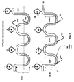
- FIG.1 of the accompanying drawings illustrates the behavior of the air and water segment in a flexible pipe arrangement.
- the waves to be regular curves, such as "U" tubes / manometers connected in series 101.
- water is filled uniformly in all the trough segments of the pipe 102, with air being trapped in the crest segments 103.
- any force applied at any point on the pipe will be transmitted throughout the length of the pipe.
- pneumatic pressure is applied at one end of the pipe 104, it will 'push' all the water segments up the crest slope of the proceeding wave 105. In other words, a pressure head will be created, which will be equal to the sum total of all the height displacements of the water segments.
- the Flexible Pipe can be made to float with the crests portion remaining above the water surface and the troughs going below it. By doing so the effective wave height can be increased from the actual wave to that assumed by the Flexible Pipe. This also helps when the actual wave heights increase.
- the Flexible Pipe absorbs the slack.
- Fig. 2 depicts an artist's impression of the FFWEC which describes the arrangement depicting the Waves moving towards the shore 202 reflected waves near shore ('turbulence' area) 203, plurality of 'Flexible Pipe' - 'Air- Water "Inlet”' 204 - 205, respectively, further connected to the 'manifold 206, further to the 'hard pipe' in the 'turbulence' area 207, terminating at the 'Air- Water Pressure Chamber' 208, with "Air' and 'Water' piping 209 connected to the generators 210 and depiction of the moorings 211, 'hard pipe supports' 212, drain pipe 213 and grid power supply 214.
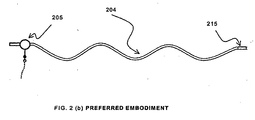
- Fig. 2 (b) is an enlarged view of the preferred embodiment essentially comprising the "Flexible Pipe", Inlet 204 -205 and Outlet 215 the outlet may further be connected to the other components.
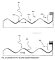
- Fig. 3 of the present invention depicts a flexible pipe floating on waves 301, with water and air slugs in sustained flow 302 & 303.
- a water reservoir / tank located at an elevation towards the outlet side of the flow representing the extent of pressure-head on the flow 304, with the direction of wave motion being from left to right 305. With no back pressure (no water in the tank) the water slugs remain in the troughs 302 and when with water in the tank, the slugs are pushed up the preceding wave crests 306 & 307.
- the air and water slugs are ingested appropriate for the operating conditions.
- water and air are alternately ingested from trough to crest and vice versa, respectively. This does not pose any problem if the load is either turned off or varied during operation.
- the FFWEC of the present invention is the only WEC to have an inherent survival capability.
- the "Flexible Pipes” can be simply submerged, by ingesting only water (no air). Since the pipes will essentially be made of specific gravity (SG) higher than that of water "one”, they will sink when filled mostly with water. To raise them again, the pneumatic pressure that would generally be available in the "pressure chamber” would be used to purge the water out of the pipes. When the pipes resurface, the system will be at "zero start state" (with no water in the Pipes).
- the flexible Pipe and the Inlet assembly are to be kept empty; else the inertia of the water already collected in the Flexible Pipe will impede zero speed start.
- the air and water intake phases or timing can be adjusted / tuned by altering the buoyancy. In both the above cases only water is ingested to sink the flexible pipe. This is achieved by completely deflating the flexible tanks or flooding the inflexible tanks of the Inlet, as applicable. For stopping, flow the buoyancy of the Inlet buoyancy tank is increased to an extent where the mouth of the Inlet cannot enter the waves. Thus, only "air” is ingested and eventually the flow stops.
- the buoyancy of the individual tanks can be varied such that the apparatus tilts either forward and back, thereby enabling adjustment of the water / air ingestion timing and even preventing the mouth of the Inflexible Pipe from ingesting water altogether. Consequently, the flow will stop after all the water slugs flow out. The flow must not be stopped either by cutting off the inflow or outflow. If resorted to it could cause severe damage to the Pipes.
- the apparatus need not essentially have any moving or contacting components. Whatever control devices required are preferably located on shore. All components of the above apparatus are made of appropriate dimensions and material. Certain design principles to achieve the desired results are discussed in the succeeding paragraphs.
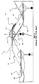
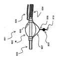
- Fig.-4 shows, the cavity being a single Inflexible Pipe protruding sufficiently ahead of the buoyancy tank 401 which normally floats on the surface of water, through the mouth 402 of which both air and water enter and the outlet of which 403 being fixedly connected with the flexible pipe 404.
- the apparatus additionally and generally consists of a suspension rod 405 with ballast 406, including mooring ring and mooring line, all suspended vertically below it with the total weight and the fulcrum thus created providing and enhancing stability to the assembly, particularly in the vertical axis, in order to minimize the pitching motion of the assembly around its lateral axis.
- the Flexible Pipe which trails the apparatus, provides the directional stability. As such, it remains nearly in upright position and rightly aligned as it floats up and down the waves.
- the Inlet generally faces the oncoming waves 410.
- the inflexible Pipe projects sufficiently ahead of the main assembly (like a gun from the turret of a tank) and is made to float at an appropriate height above the still water level, by adjusting the buoyancy. Therefore, it enters near the trough 411 and exists at the crest 412 of the waves as they pass (for explaining the sequence, the wave in the drawing is shown as stationary while the Inlet is shown in three positions, moving from right to the left).
- the water which enters it is separated from the main water body, while continuing to move through it at the same wave velocity.
- the water phase commences from the trough of an oncoming 413 wave and lasts till its crest and the air phase from thereon till the next trough 414.
- alternating intake of water and air slugs is appropriately synchronized with the waves.
- the above apparatus has no controlling devices, but can yet function under fair wave climatic conditions, with average efficiency and reliability.
- added to the above assembly is a provision for controlling and regulating the buoyancy, whereby the air and water ingestion timing and volume can be controlled to a certain degree, besides making it possible to sink the apparatus / system in bad weather or stop operations by cutting off the water intake and totally float the flexible pipes.
- the modification is described in detail below.
- Fig. 5 illustrates the above embodiment comprising of an inlet apparatus 501, the buoyancy tank 502, having a pneumatic duct 506, connected through a hose 505 to the pressure chamber with control devices preferably located thereat, for varying the pneumatic pressure in the buoyancy tank.
- control devices preferably located thereat, for varying the pneumatic pressure in the buoyancy tank.
- water breathing tube 507 By varying the pneumatic pressure in the buoyancy tank, water is pushed in/out through a water breathing tube 507, the top end of which is fixedly attached to the bottom of the buoyancy tank and the lower end opening into the sea below, consequently varying the Inlet buoyancy, thereby controlling the air and water intake timing and volume.
- the rest of the arrangements of this embodiment remain similar to those described in Fig. 4 above.
- the buoyancy tank 602 being inflatable and directly connected with the pneumatic hose 605 as above, but without the air duct and water breathing tube (the rest of the arrangements being similar to the previous embodiment described in the above paragraph).
- the buoyancy can be varied by inflating - deflating the inflatable buoyancy tank.
- two or more inflatable buoyancy tanks 702 connected individually, in groups or jointly through respective hoses 705 and 706 with the "pressure chamber", which is normally shore-based, the pneumatic pressure and controls and switching devices generally installed at the pressure chamber, the variable buoyancy tanks suitably arranged on the Inlet apparatus whereby the angle of rotation around the lateral axis of the Inlet apparatus and its buoyancy, can be controlled.
- the inflatable variable buoyancy tanks could be in the shape of doughnuts, as shown in the diagram, spherical or of any other suitable shape as in Fig. 6 and its principle operation is also similar to it.
- plurality of rigid buoyancy tanks similar in construction to the one explained at Fig. 5 above are used instead of the flexible buoyancy tanks.
Landscapes
- Engineering & Computer Science (AREA)
- Chemical & Material Sciences (AREA)
- Combustion & Propulsion (AREA)
- Mechanical Engineering (AREA)
- General Engineering & Computer Science (AREA)
- Other Liquid Machine Or Engine Such As Wave Power Use (AREA)
Abstract
Description
- This invention relates to ocean energy and more particularly wave energy converters (WEC). As against the rest of the state of the art WEC systems, which mostly capture energy from the undulations of waves or surge, almost all in the vertical axis, according to the present invention, energy is extracted from the wave propagation in the horizontal plane. A 'Flexible Pipe' floats on the surface of water and adapts to the waveform. Air and water are trapped in the pipe and segregated - due to gravity, into discrete segments or "Slugs" in the crests and troughs, respectively. The segments get pushed by the waves as they propagate from one end of it to the other. Thus, energy is extracted by virtue of the propagation of waves. The segments can flow even against pressure, if applied at the Outlet. The total pressure in a pipe will be the function of the cumulative differential pressure of all the water segments in that pipe - less losses."
- The Wave Energy Converters (WEC) has been known for many years, it was only during the last decade and a half or so that serious efforts were initiated towards exploiting it commercially. Several ocean wave energy conversion devices have since been developed, but only a few matured to full-scale trial stage, but none yet implemented fully on a commercial scale. The main disadvantage of the wave power is the uneconomical cost of extracting wave energy.
- Although several Wave Energy Converters (WEC) and many patents relating thereto are available in the world today, yet efforts are on to find truly economical and practicable solutions, particularly for application on a global scale. The main problem has been the complexity and high cost of the systems, which are further compounded by the vagaries and harshness of the ocean.
- The World Energy Council estimates that 2TW of energy could be harvested from the world's oceans, the equivalent of twice the world's electricity production. However, since waves are neither steady nor concentrated enough it has not yet been possible to extract and supply wave energy viably. The major problem with designing wave energy converters has been in handling the vast range of power variations in the ocean waves, from approximately average of 50 kW/m, peaking to 10 MW/m (a 1:200 ratio).
- Further the focus has mostly been on improving efficiency of the devices - through ever more sophistication. As such, the state of the art, wave energy converters (WEC's) have become highly sophisticated, specialized and propriety technologies. This translates into cost escalation, besides increasing the degree of difficulty in implementation and maintenance. Most importantly, it is unlikely that of any WEC of today, can be implemented with generic resources. The devices might be highly sophisticated, even more energy efficient, but perhaps, not as cost effective - in terms of cost / kW.
- Hence, a truly cost effective and simper solution, which also offers a high degree of survivability, ease of implementation and maintenance, was required.
- The state of the art power conversion devices have been generally classified into the following basic categories, namely:
- These devices generate electricity from the bobbing or pitching action of a floating object The object can be mounted to a floating raft or to a device fixed on the ocean floor. To generate large amounts of energy, a multitude of these devices must be deployed, each with its own piston and power take off equipment.
- These devices generate electricity from the wave-driven rise and fall of water in a cylindrical shaft. The rising and falling water column drives air in and out of the top of the shaft, powering an air-driven turbine.
- These shoreline devices, also called "tapered channel" or "tapchan" systems, rely on a shore-mounted structure to channel and concentrate the waves, driving them into an elevated reservoir. Water flow of this reservoir is used to generate electricity, using standard hydropower technologies.
- It is system of buoys consisting of tubular steel cylinders, attached to one another by hinges capable of interacting with a much large ocean area along its length. The force which the waves exert in moving each segment relative to its neighbors is captured by hydraulic rams that press fluid into accumulators, which, in turn, power a number of generators.
- References is also made to
USA Patent no. 4,672,222 which provides an apparatus for producing electricity from wave motion on a body of water comprising of self stabilized and niodularly expandable system of independently operative point absorbers with respective drive transmission and electrical generators. - The
application SU 1 129 407 - The
application RU 2 004 837 - The wave energy system described in
GB 2 024 957 - Similarly, the application
WO 84/00583 - It has, therefore, been long felt need to develop such wave energy converter, which overcomes the disadvantages of prior art, and energy is obtained at cheaper rate by simpler method and apparatus.
- The present invention is quite unlike the rest of the state of the art systems. Its uniqueness lies mainly in its principle of operation, as against the rest of the state of the art WEC systems, which mostly capture energy from the undulations of waves in the vertical axis or surge, the FFWEC of the present invention extracts energy from the wave propagation in the horizontal plane.
- Further, and most importantly, the FFWEC has no contacting components and moving part; besides the 'flexible pipe(s)' itself. Thus, the FFWEC is very simple in design, construction, operations, and easy to maintain.
- The FFWEC of the present invention in accordance with the features of
claim 1 consists basically of flexible pipes which float on ocean waves and convert the horizontal or progressive wave motion directly into kinetic energy, by pumping or pushing air and water through the "Flexible Pipes", which can be employed to drive conventional hydroelectricity generators or pump ocean water into reservoirs, etc. - The FFWEC of the present invention comprises essentially of a normally buoyant "Flexible Pipe" of adequate length, or plurality thereof, that floats on the ocean surface and adapts to the wave form, suitably moored so as to maintain the fore and aft axis generally perpendicular to the waves direction. A special "Inlet", integrally attached at the mouth of the flexible pipe ingests graduated slugs / segments of air and water into the flexible pipe, synchronous with the waves. The device works by using the advancing waves (wave progression) to push separate 'slugs' of water and air along the length of the pipe, thereby building up the pressure until it is sufficiently high to drive a turbine or pump ocean water into reservoirs, etc. Several such pipes could be grouped together; in series and / or parallel, to make a wave energy form.
- According to the present invention, energy is extracted from the wave propagation in the horizontal plane whereas in the rest of the state of the art WEC systems mostly capture energy from the undulations of waves or surge, almost all in the vertical axis.
- According to the present invention water and air enter/get sucked into the 'flexible pipe' through the '"Inlet"', and water gets collected in the troughs below and air trapped in the crests above, in distinct "segments", all along the length of the pipe. As waves propagate along the length of the pipe, all the segments follow the motion of the waves, with each "segment" moving along with the corresponding wave. A continuous flow of water and air is thus created.
- However, the above is true only when the water in the pipe is split up into distinct segments, with the water and air being in the troughs and crests, respectively. Else, neither pressure nor flow can develop in the pipe. Therefore, the 'flexible pipe' can also be termed as a non-positive displacement wave pump.
- If some resistance is applied at the outlet the water in the troughs will get pushed up the inclines of the previous crests, consequently increasing the pressure in the pipe. If the backpressure exceeds the total pressure head, the system stalls. The pressure is highest at the outlet, and progressively reduces up the Pipe", till it becomes negative near the inlet, thus water/air get sucked in as the waves progress.
- An Inlet is a floatable apparatus, flexibly attached at the throat of the "Flexible Pipe" through an "Inflexible Pipe", kept afloat by means of one plurality of buoyancy tanks, inflexible or flexible, with or without provision for controlling buoyancy thereof, either individually or collectively, so as to provide the desirable buoyancy and even ceasing operation by completely sinking or floating the apparatus.
- The Inlet functions to impart some Kinetic Energy to the water slug at the time of "zero" start and subsequently to ingest graduated amount / volume of air and Water, synchronous with the waves,
- In case of inclement wave climate, the inlet functions to ingest only water so as to sink the flexible pipe or plurality thereof, wherein flow ceases. And whenever required ingest only air so as to float the pipe wholly, wherein flow ceases.
- The "outlet" is a rigid pipe or a coupling located at the end of the "flexible Pipe", which could be further connected to a conventional hydropower generator or a reservoir, via a 'pressure chamber'. At near-shore locations, where reflective waves are expected, additional lengths of 'rigid pipes' may be attached to the Outlet for conveying the fluid flow to the generator-turbine or reservoir.
- With the rest of the conditions remaining constant, an increased in the number of flexibles pipes' and length, will enhances the flow volume and pressure, respectively.
- - At near-shore locations, where reflective waves are expected, additional lengths of 'rigid pipes' may be attached to the 'flexible pipe' for conveying the fluid flow to the generator housing / turbine or any other energy converter or to a reservoir.
-
-
FIG. 1 depicts the principle of the present invention. -
FIG 2 is an artist's impression of free floating wave energy converter and -
FIG 2 (b) depicts a preferred embodiment. -
FIG 3 shows air and water slugs under in a flexible pipe during idling and pressure flow conditions. -
FIG. 4 shows a typical inlet. -
FIG. 5 shows inlet with buoyancy control. - FIG. 6 shows inlet with inflatable buoyancy tank and control.
-
FIG. 7 shows inlet with plurality of inflatable buoyancy tanks and control. - Embodiments of the present invention will be described below specifically with reference to accompanying drawings.
- A good example of the "Flexible Pipe" WEC is surfing. As a surfer rides down a wave, it follows him, but not the water. In another example, say, if a thin and flexible sheet of impermeable material is spread out on a wave train and some water is poured on it, the water will immediately get collected in the troughs and start flowing along with the waves. Now, instead of the sheet above, let us use a hollow flexible pipe, as described in paragraph below:
- When the FFWEC is idling, i.e., with no load applied at the outlet, the water slugs remain in the trough part of the waves as it progresses. Whereas, under operating load the water slugs get pushed up the crest of the preceding wave all along the Flexible Pipe. This aspect has been illustrated at Fig 1 (a) and (b), respectively.
-
FIG.1 of the accompanying drawings illustrates the behavior of the air and water segment in a flexible pipe arrangement. For ease of understanding, we have considered the waves to be regular curves, such as "U" tubes / manometers connected inseries 101. Let us also assume that, initially, water is filled uniformly in all the trough segments of thepipe 102, with air being trapped in thecrest segments 103. It can be seen that, since all the segments are connected in series, any force applied at any point on the pipe will be transmitted throughout the length of the pipe. Thus, if pneumatic pressure is applied at one end of the pipe 104, it will 'push' all the water segments up the crest slope of theproceeding wave 105. In other words, a pressure head will be created, which will be equal to the sum total of all the height displacements of the water segments. - For example, if there are 3 waves of
H 1 mtr. each (water displacement in each segment), the cumulative head will be == 3 mtrs. (max.) (which can theoretically be increased till infinity). - Now, instead of above experiment, if we consider a wave train, the opposite will happen; that is, pressure will be generated and the water / air segments will start flowing in the pipe along with the wave train. The invention exploits this characteristic of the wave motion.
- The energy that can be generated by a pipe can be calculated by: P/1= 0.55 Hc2 x Ts per unit crest length, with Hc being the significant wave height and Ts the period of the wave. This is the total power per length of the wave and as this energy is being extracted from the surface, the energy that is below the wave would rise up to replace it, till almost all of the energy that existed above and below the wave is progressively extracted. Therefore, the maximum energy which the "flexible pipe" can extract will be all along its length - much more than that by a "point absorber".
- During normal operating conditions, the Flexible Pipe can be made to float with the crests portion remaining above the water surface and the troughs going below it. By doing so the effective wave height can be increased from the actual wave to that assumed by the Flexible Pipe. This also helps when the actual wave heights increase. The Flexible Pipe absorbs the slack.
-
Fig. 2 depicts an artist's impression of the FFWEC which describes the arrangement depicting the Waves moving towards theshore 202 reflected waves near shore ('turbulence' area) 203, plurality of 'Flexible Pipe' - 'Air- Water "Inlet"' 204 - 205, respectively, further connected to the 'manifold 206, further to the 'hard pipe' in the 'turbulence'area 207, terminating at the 'Air- Water Pressure Chamber' 208, with "Air' and 'Water' piping 209 connected to thegenerators 210 and depiction of themoorings 211, 'hard pipe supports' 212, drain pipe 213 andgrid power supply 214. -
Fig. 2 (b) is an enlarged view of the preferred embodiment essentially comprising the "Flexible Pipe", Inlet 204 -205 andOutlet 215 the outlet may further be connected to the other components. -
Fig. 3 of the present invention depicts a flexible pipe floating onwaves 301, with water and air slugs insustained flow 302 & 303. A water reservoir / tank located at an elevation towards the outlet side of the flow representing the extent of pressure-head on theflow 304, with the direction of wave motion being from left to right 305. With no back pressure (no water in the tank) the water slugs remain in thetroughs 302 and when with water in the tank, the slugs are pushed up the preceding wave crests 306 & 307. - It is preferable that the air and water slugs are ingested appropriate for the operating conditions. As such, in each phase of the wave, normally water and air are alternately ingested from trough to crest and vice versa, respectively. This does not pose any problem if the load is either turned off or varied during operation.
- Incidentally, with the above possibility, we could categorize the FFWEC as a "Linear Absorber" type as against the "Point Absorber".
- The water mass on the surface of the ocean does not move along with the waves, only the waveform does. Further, ocean waves posses two types of energy - kinetic and potential. The former is by the virtue of the horizontal progression of waveform and the latter due to heaving motion or the height difference between the wave crest and trough - wave height. Since water inside the flexible pipe flows at the wave velocity and in phase with the waves, at the time of initial start the Inlet must ingest and accelerate slugs of water from the initial "zero" relative velocity to that of the waves, both at the right moment and within a very short period of time (less than a half wave period). This is achieved by making use of either one or both the types of the wave energy mentioned above.
- The FFWEC of the present invention is the only WEC to have an inherent survival capability. During severe wave climate, the "Flexible Pipes" can be simply submerged, by ingesting only water (no air). Since the pipes will essentially be made of specific gravity (SG) higher than that of water "one", they will sink when filled mostly with water. To raise them again, the pneumatic pressure that would generally be available in the "pressure chamber" would be used to purge the water out of the pipes. When the pipes resurface, the system will be at "zero start state" (with no water in the Pipes).
- Before commencing operation (flow), the flexible Pipe and the Inlet assembly are to be kept empty; else the inertia of the water already collected in the Flexible Pipe will impede zero speed start. During operation, the air and water intake phases or timing can be adjusted / tuned by altering the buoyancy. In both the above cases only water is ingested to sink the flexible pipe. This is achieved by completely deflating the flexible tanks or flooding the inflexible tanks of the Inlet, as applicable. For stopping, flow the buoyancy of the Inlet buoyancy tank is increased to an extent where the mouth of the Inlet cannot enter the waves. Thus, only "air" is ingested and eventually the flow stops.
- Alternatively the buoyancy of the individual tanks can be varied such that the apparatus tilts either forward and back, thereby enabling adjustment of the water / air ingestion timing and even preventing the mouth of the Inflexible Pipe from ingesting water altogether. Consequently, the flow will stop after all the water slugs flow out. The flow must not be stopped either by cutting off the inflow or outflow. If resorted to it could cause severe damage to the Pipes. The apparatus need not essentially have any moving or contacting components. Whatever control devices required are preferably located on shore. All components of the above apparatus are made of appropriate dimensions and material.
Certain design principles to achieve the desired results are discussed in the succeeding paragraphs. - The basic embodiment in Fig.-4 shows, the cavity being a single Inflexible Pipe protruding sufficiently ahead of the
buoyancy tank 401 which normally floats on the surface of water, through themouth 402 of which both air and water enter and the outlet of which 403 being fixedly connected with theflexible pipe 404. Further, the apparatus additionally and generally consists of asuspension rod 405 withballast 406, including mooring ring and mooring line, all suspended vertically below it with the total weight and the fulcrum thus created providing and enhancing stability to the assembly, particularly in the vertical axis, in order to minimize the pitching motion of the assembly around its lateral axis. Further more, in order to minimize the torque that would be created by the moment arm formed due to the distance between the centre of pressure (CP) and center of gravity (CG) both being kept co-centric or nearest thereto. The Flexible Pipe, which trails the apparatus, provides the directional stability. As such, it remains nearly in upright position and rightly aligned as it floats up and down the waves. - The Inlet generally faces the oncoming waves 410. The inflexible Pipe projects sufficiently ahead of the main assembly (like a gun from the turret of a tank) and is made to float at an appropriate height above the still water level, by adjusting the buoyancy. Therefore, it enters near the
trough 411 and exists at thecrest 412 of the waves as they pass (for explaining the sequence, the wave in the drawing is shown as stationary while the Inlet is shown in three positions, moving from right to the left). When a wave strikes the mouth of the Inflexible Pipe the water which enters it is separated from the main water body, while continuing to move through it at the same wave velocity. The water phase commences from the trough of an oncoming 413 wave and lasts till its crest and the air phase from thereon till thenext trough 414. Thus, alternating intake of water and air slugs is appropriately synchronized with the waves. - The above apparatus has no controlling devices, but can yet function under fair wave climatic conditions, with average efficiency and reliability.
- In another embodiment, added to the above assembly is a provision for controlling and regulating the buoyancy, whereby the air and water ingestion timing and volume can be controlled to a certain degree, besides making it possible to sink the apparatus / system in bad weather or stop operations by cutting off the water intake and totally float the flexible pipes. The modification is described in detail below.
-
Fig. 5 , illustrates the above embodiment comprising of aninlet apparatus 501, thebuoyancy tank 502, having apneumatic duct 506, connected through ahose 505 to the pressure chamber with control devices preferably located thereat, for varying the pneumatic pressure in the buoyancy tank. By varying the pneumatic pressure in the buoyancy tank, water is pushed in/out through awater breathing tube 507, the top end of which is fixedly attached to the bottom of the buoyancy tank and the lower end opening into the sea below, consequently varying the Inlet buoyancy, thereby controlling the air and water intake timing and volume. The rest of the arrangements of this embodiment remain similar to those described inFig. 4 above. - In another embodiment which is illustrated by Fig. 6, the
buoyancy tank 602 being inflatable and directly connected with thepneumatic hose 605 as above, but without the air duct and water breathing tube (the rest of the arrangements being similar to the previous embodiment described in the above paragraph). As can be appreciated, the buoyancy can be varied by inflating - deflating the inflatable buoyancy tank. - In yet another embodiment illustrated by
Fig. 7 , two or moreinflatable buoyancy tanks 702, connected individually, in groups or jointly throughrespective hoses - The inflatable variable buoyancy tanks could be in the shape of doughnuts, as shown in the diagram, spherical or of any other suitable shape as in Fig. 6 and its principle operation is also similar to it.
- In the above embodiment, plurality of rigid buoyancy tanks similar in construction to the one explained at
Fig. 5 above are used instead of the flexible buoyancy tanks. - From the foregoing, it could be appreciated that the FFWEC could offer several advantages over the state of the art wave energy conversion systems. These are as follows:
- The simplest WEC concept comprising of no contacting parts
- Least Cost/KW (only flexible pipes absorb the wave energy).
- Utilizes components and sub-systems that are readily available (we only need to select the most suitable components).
- The technologies used are well matured (mostly 'brick and mortar - minimum hi-tech).
- Has very high survivability factor under stormy conditions (it submerges, like a submarine).
- Large-scale deployment possible, within a short time period utilising local resources.
- Highly cost competitive - Design & Development, Capital, O&M and Production, etc. as compared with the existing state of the art WEC systems and comparable with the conventional electricity generating systems.
- Very easy to-install /-un-install and maintain. Only the 'flexible pipes' and rigid pipes are to be laid on the ocean. The same being very light in weight can be implemented with the help of standard vessels and crew even on a very large scale.
- Conventional mooring, system.
- The concept is rather simple. Involved R&D is not envisaged, i.e. fast tracking - concept evaluation and prototype testing through to commercial deployment.
- Does not pose threat to marine life - eco-friendly.
- The invention is technically feasible and commercially viable.
Claims (15)
- A wave energy converter comprising:- a flexible pipe (204, 301 or 404) extending between an inlet end (205) and an outlet end (215); andcharacterized in that the wave energy converter comprises- an inflexible inlet pipe (205) having an open inlet end and an outlet end (403) connected in fluid communication with said inlet end of said flexible pipe; and- a buoyancy tank (401, 502, 602 or 702) attached to said inlet pipe for keeping afloat and/or tilting forward and back said inlet pipe in a body of water; andwherein the inlet ingests graduated slugs of air and water into the flexible pipe, synchronous with the waves and wherein the converter is suitably moored to maintain the fore and aft axis generally perpendicular to the waves direction.
- The wave energy converter according to claim 1 including a water breathing tube (507) having a top end connected in fluid communication with a bottom of an interior of said buoyancy tank and a lower end opening into the body of water.
- The wave energy converter according to claim 2 including a pneumatic duct (506) having a top end positioned in a top of said interior of said buoyancy tank and a pneumatic hose (505) connected to said pneumatic duct for varying a pneumatic pressure in said interior of said buoyancy tank.
- The wave energy converter according to claim 1 wherein said buoyancy tank is inflatable and is connected to a pneumatic pressure source through a pneumatic hose.
- The wave energy converter according to claim 1 including a generator for generating electricity.
- The wave energy converter according to claim 1 including at least another buoyancy tank attached to said inlet pipe and means for controlling a buoyancy of said buoyancy tanks whereby the air and water ingestion timing and volume can be controlled.
- The wave energy converter according to any one of claim 1 to 6 including a suspension rod (405) with a ballast (406) extending from a bottom of the said buoyancy tank for providing stability in a vertical axis.
- The wave energy converter according to any one of claims 1 to 7 including a pressure chamber (208) connected in fluid communication with said outlet end of said flexible pipe.
- The wave energy converter according to claim 8 including a rigid outlet pipe (207) having an inlet end connected in fluid communication with said outlet end of said flexible pipe and an outlet end connected in fluid communication with said pressure chamber, said outlet pipe being positioned in a turbulence area near a shore of the body of water.
- A wave energy converter according to claim 1 comprising:- a plurality of flexible pipes (204) each extending between an inlet end and an outlet end;- a plurality of inflexible inlet pipes (205) each having an open inlet end and an outlet end connected in fluid communication with said inlet end of an associated one of said flexible pipes;- a plurality of buoyancy tanks (702) each attached to an associated one of said inlet pipes for floating said inlet pipes in a body of water; and- a manifold (206) connected in fluid communication with said outlet end of each of said flexible pipes.
- The wave energy converter according to claim 10 including a rigid outlet pipe (207) having an inlet end connected in fluid communication with said manifold and an outlet end, said outlet pipe being positioned in a turbulence area (203) near a shore of the body of water.
- The wave energy converter according to claim 10 including a generator (210) connected to said manifold for generating electricity.
- The wave energy converter according to claim 10 including at least another buoyancy tank attached to each of said inlet pipes and means for varying a buoyancy of said buoyancy tanks to adjust lengths of the alternating slugs of water and air entering said inlet pipes.
- The wave energy converter according to any one of claim 10 to 13 including a suspension rod (405) with a ballast (406) extending from a bottom of the said buoyancy tank for providing stability in a vertical axis.
- The wave energy converter according to any one of claim 10 to 14 including a pressure chamber (208) connected in fluid communication with said manifold for building up and making available pneumatic pressure.
Applications Claiming Priority (2)
| Application Number | Priority Date | Filing Date | Title |
|---|---|---|---|
| IN694KO2005 | 2005-08-02 | ||
| PCT/IN2006/000273 WO2007015269A1 (en) | 2005-08-02 | 2006-08-01 | Free floating wave energy converter |
Publications (2)
| Publication Number | Publication Date |
|---|---|
| EP1915528A1 EP1915528A1 (en) | 2008-04-30 |
| EP1915528B1 true EP1915528B1 (en) | 2012-05-30 |
Family
ID=37243603
Family Applications (1)
| Application Number | Title | Priority Date | Filing Date |
|---|---|---|---|
| EP06780553A Revoked EP1915528B1 (en) | 2005-08-02 | 2006-08-01 | Free floating wave energy converter |
Country Status (12)
| Country | Link |
|---|---|
| US (1) | US7823380B2 (en) |
| EP (1) | EP1915528B1 (en) |
| JP (1) | JP5149179B2 (en) |
| AU (1) | AU2006274564B2 (en) |
| BR (1) | BRPI0614487A2 (en) |
| CA (1) | CA2617208A1 (en) |
| ES (1) | ES2389361T3 (en) |
| NO (1) | NO20081115L (en) |
| NZ (1) | NZ566247A (en) |
| PT (1) | PT1915528E (en) |
| WO (1) | WO2007015269A1 (en) |
| ZA (1) | ZA200801801B (en) |
Cited By (1)
| Publication number | Priority date | Publication date | Assignee | Title |
|---|---|---|---|---|
| WO2013014682A2 (en) | 2011-07-22 | 2013-01-31 | Syed Mohammed Ghouse | An improved free floatfng wave energy converter |
Families Citing this family (33)
| Publication number | Priority date | Publication date | Assignee | Title |
|---|---|---|---|---|
| GB2434840B (en) * | 2006-02-04 | 2011-10-19 | Francis James Macdonald Farley | Distensible tube wave energy converter |
| SE529687C2 (en) * | 2007-01-22 | 2007-10-23 | Daniel Ehrnberg | Wave-power aggregate for extracting energy from wave motion in fluid, used in sea, has first and second portions which are configured to arrange in first and second positions when under influence of wave motion |
| US8432057B2 (en) * | 2007-05-01 | 2013-04-30 | Pliant Energy Systems Llc | Pliant or compliant elements for harnessing the forces of moving fluid to transport fluid or generate electricity |
| US9145875B2 (en) | 2007-05-01 | 2015-09-29 | Pliant Energy Systems Llc | Ribbon transducer and pump apparatuses, methods and systems |
| US7696634B2 (en) * | 2007-05-01 | 2010-04-13 | Pliant Energy Systems Llc | Pliant mechanisms for extracting power from moving fluid |
| US8610304B2 (en) | 2007-05-01 | 2013-12-17 | Pliant Energy Systems Llc | Mechanisms for creating undulating motion, such as for propulsion, and for harnessing the energy of moving fluid |
| EP2034177A1 (en) * | 2007-09-05 | 2009-03-11 | Earthfly Holding GmbH | Method and device for generating energy from hydropower |
| GB2458630A (en) * | 2008-02-28 | 2009-09-30 | Aws Ocean Energy Ltd | Deformable wave energy converter with electroactive material |
| EP2307705A1 (en) * | 2008-07-17 | 2011-04-13 | Jospa Limited | A wave energy converter |
| BR112012001556A2 (en) * | 2009-07-21 | 2021-01-12 | Pliant Energy Systems Llc | energy generator, mechanism for extracting energy from a directional flow of a fluid, energy extraction apparatus and system, and methods for extracting energy from a flow fluid, and for forming an apparatus for extracting energy. |
| US20110057448A1 (en) * | 2009-09-08 | 2011-03-10 | Joseph Page | Wave energy converters |
| GB2475049A (en) * | 2009-11-03 | 2011-05-11 | Norman West Bellamy | Pneumatic wave compressor for extracting energy from sea waves |
| CL2009002049A1 (en) * | 2009-11-09 | 2010-02-26 | Requena Rivera Rodolfo | Device for pumping seawater using the movement of the sea and waves, it has a flexible aqueduct composed of a set of elastic pipes with floats, a coupling piece and a unidirectional valve at the ends, said pipe attached to a tank that pivots in a fixed structure to seabed. |
| US20120247589A1 (en) | 2009-12-07 | 2012-10-04 | Patrick Joseph Duffy | Wave energy conversion |
| SE536685C2 (en) * | 2011-10-18 | 2014-05-27 | Vigor Wave Energy Ab | Wave power unit |
| WO2014107125A1 (en) * | 2013-01-03 | 2014-07-10 | Vigor Wave Energy Ab | A wave power unit |
| US9074577B2 (en) | 2013-03-15 | 2015-07-07 | Dehlsen Associates, Llc | Wave energy converter system |
| US9810193B2 (en) * | 2014-06-17 | 2017-11-07 | Michael Ingle | Convertible water pump |
| CA2954955A1 (en) | 2014-07-14 | 2016-01-21 | Captain Syed Mohammed Ghouse Group | A free floating wave energy converter having variable buoyancy flexible pipe and enhanced capture width |
| US11209022B2 (en) | 2016-06-30 | 2021-12-28 | Pliant Energy Systems Llc | Vehicle with traveling wave thrust module apparatuses, methods and systems |
| US11795900B2 (en) | 2016-06-30 | 2023-10-24 | Pliant Energy Systems Llc | Vehicle with traveling wave thrust module apparatuses, methods and systems |
| US10190570B1 (en) | 2016-06-30 | 2019-01-29 | Pliant Energy Systems Llc | Traveling wave propeller, pump and generator apparatuses, methods and systems |
| US10519926B2 (en) | 2016-06-30 | 2019-12-31 | Pliant Energy Systems Llc | Traveling wave propeller, pump and generator apparatuses, methods and systems |
| US9957018B1 (en) * | 2017-02-07 | 2018-05-01 | Cvetan Angeliev | System for wave amplifying, wave energy harnessing, and energy storage |
| US10443593B2 (en) * | 2017-02-13 | 2019-10-15 | Walter Chen | Fresh water transport method utilizing anchored buoyant units powered by the changing height of a local tide |
| ES2890973T3 (en) * | 2017-08-04 | 2022-01-25 | Teknoplan As | Wave power plant with controllable floating buoys |
| GB2571936B (en) * | 2018-03-12 | 2020-10-28 | Fortitudo Maris Ltd | Improved wave energy capture system |
| WO2019210277A1 (en) | 2018-04-27 | 2019-10-31 | Pliant Energy Systems Llc | Apparatuses, methods and systems for harnessing the energy of fluid flow to generate electricity or pump fluid |
| US11156201B2 (en) * | 2018-05-17 | 2021-10-26 | Lone Gull Holdings, Ltd. | Inertial pneumatic wave energy device |
| US10837420B2 (en) | 2018-10-31 | 2020-11-17 | Loubert S. Suddaby | Wave energy capture device and energy storage system utilizing a variable mass, variable radius concentric ring flywheel |
| US10788011B2 (en) | 2018-10-31 | 2020-09-29 | Loubert S. Suddaby | Wave energy capture device and energy storage system utilizing a variable mass, variable radius concentric ring flywheel |
| IL281592A (en) * | 2021-03-17 | 2022-10-01 | MAHLEV Yehezkel | A turbine propulsion system, based on sea waves energy |
| US20230115891A1 (en) * | 2021-10-08 | 2023-04-13 | Lawrence Livermore National Security, Llc | System for direct air capture using ocean energy and fluidics principles |
Family Cites Families (11)
| Publication number | Priority date | Publication date | Assignee | Title |
|---|---|---|---|---|
| US3335667A (en) * | 1965-10-21 | 1967-08-15 | Murphy James | Wave machine and means for raising water |
| US4163633A (en) * | 1976-12-01 | 1979-08-07 | Vriend Joseph A | Apparatus for producing power from water waves |
| GB2024957A (en) | 1978-07-06 | 1980-01-16 | British Petroleum Co | Wave energy device |
| DK148925C (en) | 1982-08-03 | 1986-05-12 | Kristian Dahl Hertz | PLANT TO USE THE ENERGY IN A SURFACE WAVER, EX. BULK ON A SURFACE SURFACE |
| SU1129407A1 (en) | 1983-08-22 | 1984-12-15 | Киевский Ордена Ленина Политехнический Институт Им.50-Летия Великой Октябрьской Социалистической Революции | Guiding arrangement of wave power plant |
| US4672222A (en) | 1986-03-13 | 1987-06-09 | Ames P Foerd | Ocean wave energy converter |
| JPH03151572A (en) * | 1989-11-07 | 1991-06-27 | Setsuo Toi | Wave power generation utilizing tube |
| RU2004837C1 (en) | 1990-01-17 | 1993-12-15 | нцев Леонид Иванович Рум | Wave plant |
| US5808368A (en) * | 1996-11-05 | 1998-09-15 | Brown; Clifford H. | Ocean wave energy conversion device |
| US20060090463A1 (en) | 2002-06-27 | 2006-05-04 | Burns Alan R | Wave energy converter |
| GB0428198D0 (en) * | 2004-12-22 | 2005-01-26 | Salt Anthony | Energy extraction apparatus and method |
-
2006
- 2006-08-01 WO PCT/IN2006/000273 patent/WO2007015269A1/en active Application Filing
- 2006-08-01 ES ES06780553T patent/ES2389361T3/en active Active
- 2006-08-01 PT PT06780553T patent/PT1915528E/en unknown
- 2006-08-01 BR BRPI0614487-0A patent/BRPI0614487A2/en not_active IP Right Cessation
- 2006-08-01 CA CA002617208A patent/CA2617208A1/en not_active Abandoned
- 2006-08-01 JP JP2008524678A patent/JP5149179B2/en not_active Expired - Fee Related
- 2006-08-01 NZ NZ566247A patent/NZ566247A/en not_active IP Right Cessation
- 2006-08-01 US US11/997,662 patent/US7823380B2/en not_active Expired - Fee Related
- 2006-08-01 AU AU2006274564A patent/AU2006274564B2/en not_active Ceased
- 2006-08-01 EP EP06780553A patent/EP1915528B1/en not_active Revoked
-
2008
- 2008-02-26 ZA ZA200801801A patent/ZA200801801B/en unknown
- 2008-03-03 NO NO20081115A patent/NO20081115L/en not_active Application Discontinuation
Cited By (1)
| Publication number | Priority date | Publication date | Assignee | Title |
|---|---|---|---|---|
| WO2013014682A2 (en) | 2011-07-22 | 2013-01-31 | Syed Mohammed Ghouse | An improved free floatfng wave energy converter |
Also Published As
| Publication number | Publication date |
|---|---|
| EP1915528A1 (en) | 2008-04-30 |
| JP2009503362A (en) | 2009-01-29 |
| US7823380B2 (en) | 2010-11-02 |
| BRPI0614487A2 (en) | 2011-03-29 |
| NO20081115L (en) | 2008-04-30 |
| US20080229745A1 (en) | 2008-09-25 |
| CA2617208A1 (en) | 2007-02-08 |
| ES2389361T3 (en) | 2012-10-25 |
| JP5149179B2 (en) | 2013-02-20 |
| PT1915528E (en) | 2012-08-24 |
| ZA200801801B (en) | 2009-03-25 |
| NZ566247A (en) | 2011-09-30 |
| AU2006274564A1 (en) | 2007-02-08 |
| AU2006274564B2 (en) | 2012-04-12 |
| WO2007015269A1 (en) | 2007-02-08 |
Similar Documents
| Publication | Publication Date | Title |
|---|---|---|
| EP1915528B1 (en) | Free floating wave energy converter | |
| US7607862B2 (en) | Shoaling water energy conversion device | |
| US9074577B2 (en) | Wave energy converter system | |
| US9797367B2 (en) | Wave energy conversion | |
| US8429910B2 (en) | Free floating wave energy converter | |
| US20120317970A1 (en) | Wave power plant | |
| US20090261593A1 (en) | Tidal pump generator | |
| JP3530871B2 (en) | Hydro, wave and wind energy converters | |
| GB2414771A (en) | A wave power generator apparatus | |
| CN104895735A (en) | Whale-shaped wave power generation device | |
| WO2016177858A1 (en) | A wave-powered electrical energy generation device | |
| EP4119788B1 (en) | An apparatus and a method for extracting hydrostatic energy from sea waves | |
| WO2004090325A1 (en) | Reciprocating blade system for energy extraction from currents |
Legal Events
| Date | Code | Title | Description |
|---|---|---|---|
| PUAI | Public reference made under article 153(3) epc to a published international application that has entered the european phase |
Free format text: ORIGINAL CODE: 0009012 |
|
| 17P | Request for examination filed |
Effective date: 20080303 |
|
| AK | Designated contracting states |
Kind code of ref document: A1 Designated state(s): AT BE BG CH CY CZ DE DK EE ES FI FR GB GR HU IE IS IT LI LT LU LV MC NL PL PT RO SE SI SK TR |
|
| 17Q | First examination report despatched |
Effective date: 20091125 |
|
| GRAP | Despatch of communication of intention to grant a patent |
Free format text: ORIGINAL CODE: EPIDOSNIGR1 |
|
| DAX | Request for extension of the european patent (deleted) | ||
| GRAS | Grant fee paid |
Free format text: ORIGINAL CODE: EPIDOSNIGR3 |
|
| GRAA | (expected) grant |
Free format text: ORIGINAL CODE: 0009210 |
|
| AK | Designated contracting states |
Kind code of ref document: B1 Designated state(s): AT BE BG CH CY CZ DE DK EE ES FI FR GB GR HU IE IS IT LI LT LU LV MC NL PL PT RO SE SI SK TR |
|
| REG | Reference to a national code |
Ref country code: GB Ref legal event code: FG4D |
|
| REG | Reference to a national code |
Ref country code: CH Ref legal event code: EP |
|
| REG | Reference to a national code |
Ref country code: AT Ref legal event code: REF Ref document number: 560195 Country of ref document: AT Kind code of ref document: T Effective date: 20120615 |
|
| REG | Reference to a national code |
Ref country code: IE Ref legal event code: FG4D |
|
| REG | Reference to a national code |
Ref country code: DE Ref legal event code: R096 Ref document number: 602006029838 Country of ref document: DE Effective date: 20120726 |
|
| REG | Reference to a national code |
Ref country code: PT Ref legal event code: SC4A Free format text: AVAILABILITY OF NATIONAL TRANSLATION Effective date: 20120817 |
|
| REG | Reference to a national code |
Ref country code: NL Ref legal event code: VDEP Effective date: 20120530 |
|
| REG | Reference to a national code |
Ref country code: LT Ref legal event code: MG4D Effective date: 20120530 Ref country code: ES Ref legal event code: FG2A Ref document number: 2389361 Country of ref document: ES Kind code of ref document: T3 Effective date: 20121025 |
|
| PG25 | Lapsed in a contracting state [announced via postgrant information from national office to epo] |
Ref country code: FI Free format text: LAPSE BECAUSE OF FAILURE TO SUBMIT A TRANSLATION OF THE DESCRIPTION OR TO PAY THE FEE WITHIN THE PRESCRIBED TIME-LIMIT Effective date: 20120530 Ref country code: SE Free format text: LAPSE BECAUSE OF FAILURE TO SUBMIT A TRANSLATION OF THE DESCRIPTION OR TO PAY THE FEE WITHIN THE PRESCRIBED TIME-LIMIT Effective date: 20120530 Ref country code: LT Free format text: LAPSE BECAUSE OF FAILURE TO SUBMIT A TRANSLATION OF THE DESCRIPTION OR TO PAY THE FEE WITHIN THE PRESCRIBED TIME-LIMIT Effective date: 20120530 Ref country code: CY Free format text: LAPSE BECAUSE OF FAILURE TO SUBMIT A TRANSLATION OF THE DESCRIPTION OR TO PAY THE FEE WITHIN THE PRESCRIBED TIME-LIMIT Effective date: 20120530 Ref country code: IS Free format text: LAPSE BECAUSE OF FAILURE TO SUBMIT A TRANSLATION OF THE DESCRIPTION OR TO PAY THE FEE WITHIN THE PRESCRIBED TIME-LIMIT Effective date: 20120930 |
|
| REG | Reference to a national code |
Ref country code: AT Ref legal event code: MK05 Ref document number: 560195 Country of ref document: AT Kind code of ref document: T Effective date: 20120530 |
|
| PG25 | Lapsed in a contracting state [announced via postgrant information from national office to epo] |
Ref country code: GR Free format text: LAPSE BECAUSE OF FAILURE TO SUBMIT A TRANSLATION OF THE DESCRIPTION OR TO PAY THE FEE WITHIN THE PRESCRIBED TIME-LIMIT Effective date: 20120831 Ref country code: LV Free format text: LAPSE BECAUSE OF FAILURE TO SUBMIT A TRANSLATION OF THE DESCRIPTION OR TO PAY THE FEE WITHIN THE PRESCRIBED TIME-LIMIT Effective date: 20120530 Ref country code: SI Free format text: LAPSE BECAUSE OF FAILURE TO SUBMIT A TRANSLATION OF THE DESCRIPTION OR TO PAY THE FEE WITHIN THE PRESCRIBED TIME-LIMIT Effective date: 20120530 |
|
| PG25 | Lapsed in a contracting state [announced via postgrant information from national office to epo] |
Ref country code: BE Free format text: LAPSE BECAUSE OF FAILURE TO SUBMIT A TRANSLATION OF THE DESCRIPTION OR TO PAY THE FEE WITHIN THE PRESCRIBED TIME-LIMIT Effective date: 20120530 |
|
| PG25 | Lapsed in a contracting state [announced via postgrant information from national office to epo] |
Ref country code: NL Free format text: LAPSE BECAUSE OF FAILURE TO SUBMIT A TRANSLATION OF THE DESCRIPTION OR TO PAY THE FEE WITHIN THE PRESCRIBED TIME-LIMIT Effective date: 20120530 Ref country code: SK Free format text: LAPSE BECAUSE OF FAILURE TO SUBMIT A TRANSLATION OF THE DESCRIPTION OR TO PAY THE FEE WITHIN THE PRESCRIBED TIME-LIMIT Effective date: 20120530 Ref country code: DK Free format text: LAPSE BECAUSE OF FAILURE TO SUBMIT A TRANSLATION OF THE DESCRIPTION OR TO PAY THE FEE WITHIN THE PRESCRIBED TIME-LIMIT Effective date: 20120530 Ref country code: EE Free format text: LAPSE BECAUSE OF FAILURE TO SUBMIT A TRANSLATION OF THE DESCRIPTION OR TO PAY THE FEE WITHIN THE PRESCRIBED TIME-LIMIT Effective date: 20120530 Ref country code: CZ Free format text: LAPSE BECAUSE OF FAILURE TO SUBMIT A TRANSLATION OF THE DESCRIPTION OR TO PAY THE FEE WITHIN THE PRESCRIBED TIME-LIMIT Effective date: 20120530 Ref country code: RO Free format text: LAPSE BECAUSE OF FAILURE TO SUBMIT A TRANSLATION OF THE DESCRIPTION OR TO PAY THE FEE WITHIN THE PRESCRIBED TIME-LIMIT Effective date: 20120530 Ref country code: AT Free format text: LAPSE BECAUSE OF FAILURE TO SUBMIT A TRANSLATION OF THE DESCRIPTION OR TO PAY THE FEE WITHIN THE PRESCRIBED TIME-LIMIT Effective date: 20120530 |
|
| PG25 | Lapsed in a contracting state [announced via postgrant information from national office to epo] |
Ref country code: IT Free format text: LAPSE BECAUSE OF FAILURE TO SUBMIT A TRANSLATION OF THE DESCRIPTION OR TO PAY THE FEE WITHIN THE PRESCRIBED TIME-LIMIT Effective date: 20120530 Ref country code: PL Free format text: LAPSE BECAUSE OF FAILURE TO SUBMIT A TRANSLATION OF THE DESCRIPTION OR TO PAY THE FEE WITHIN THE PRESCRIBED TIME-LIMIT Effective date: 20120530 |
|
| PLBI | Opposition filed |
Free format text: ORIGINAL CODE: 0009260 |
|
| REG | Reference to a national code |
Ref country code: DE Ref legal event code: R119 Ref document number: 602006029838 Country of ref document: DE |
|
| REG | Reference to a national code |
Ref country code: CH Ref legal event code: PL |
|
| PG25 | Lapsed in a contracting state [announced via postgrant information from national office to epo] |
Ref country code: MC Free format text: LAPSE BECAUSE OF NON-PAYMENT OF DUE FEES Effective date: 20120831 |
|
| 26 | Opposition filed |
Opponent name: PISCATOR, JOHAN Effective date: 20130227 |
|
| PLAX | Notice of opposition and request to file observation + time limit sent |
Free format text: ORIGINAL CODE: EPIDOSNOBS2 |
|
| PG25 | Lapsed in a contracting state [announced via postgrant information from national office to epo] |
Ref country code: CH Free format text: LAPSE BECAUSE OF NON-PAYMENT OF DUE FEES Effective date: 20120831 Ref country code: LI Free format text: LAPSE BECAUSE OF NON-PAYMENT OF DUE FEES Effective date: 20120831 |
|
| REG | Reference to a national code |
Ref country code: DE Ref legal event code: R026 Ref document number: 602006029838 Country of ref document: DE Effective date: 20130227 |
|
| PG25 | Lapsed in a contracting state [announced via postgrant information from national office to epo] |
Ref country code: BG Free format text: LAPSE BECAUSE OF FAILURE TO SUBMIT A TRANSLATION OF THE DESCRIPTION OR TO PAY THE FEE WITHIN THE PRESCRIBED TIME-LIMIT Effective date: 20120830 Ref country code: DE Free format text: LAPSE BECAUSE OF NON-PAYMENT OF DUE FEES Effective date: 20130301 |
|
| PLAF | Information modified related to communication of a notice of opposition and request to file observations + time limit |
Free format text: ORIGINAL CODE: EPIDOSCOBS2 |
|
| REG | Reference to a national code |
Ref country code: DE Ref legal event code: R119 Ref document number: 602006029838 Country of ref document: DE Effective date: 20130301 |
|
| PGFP | Annual fee paid to national office [announced via postgrant information from national office to epo] |
Ref country code: IE Payment date: 20130826 Year of fee payment: 8 Ref country code: PT Payment date: 20120817 Year of fee payment: 8 Ref country code: ES Payment date: 20130826 Year of fee payment: 8 |
|
| PLBB | Reply of patent proprietor to notice(s) of opposition received |
Free format text: ORIGINAL CODE: EPIDOSNOBS3 |
|
| PGFP | Annual fee paid to national office [announced via postgrant information from national office to epo] |
Ref country code: FR Payment date: 20130819 Year of fee payment: 8 Ref country code: GB Payment date: 20130827 Year of fee payment: 8 |
|
| PLAB | Opposition data, opponent's data or that of the opponent's representative modified |
Free format text: ORIGINAL CODE: 0009299OPPO |
|
| R26 | Opposition filed (corrected) |
Opponent name: PISCATOR, JOHAN Effective date: 20130227 |
|
| PG25 | Lapsed in a contracting state [announced via postgrant information from national office to epo] |
Ref country code: TR Free format text: LAPSE BECAUSE OF FAILURE TO SUBMIT A TRANSLATION OF THE DESCRIPTION OR TO PAY THE FEE WITHIN THE PRESCRIBED TIME-LIMIT Effective date: 20120530 |
|
| PG25 | Lapsed in a contracting state [announced via postgrant information from national office to epo] |
Ref country code: LU Free format text: LAPSE BECAUSE OF NON-PAYMENT OF DUE FEES Effective date: 20120801 |
|
| PG25 | Lapsed in a contracting state [announced via postgrant information from national office to epo] |
Ref country code: HU Free format text: LAPSE BECAUSE OF FAILURE TO SUBMIT A TRANSLATION OF THE DESCRIPTION OR TO PAY THE FEE WITHIN THE PRESCRIBED TIME-LIMIT Effective date: 20060801 |
|
| REG | Reference to a national code |
Ref country code: PT Ref legal event code: MM4A Free format text: LAPSE DUE TO NON-PAYMENT OF FEES Effective date: 20150202 |
|
| GBPC | Gb: european patent ceased through non-payment of renewal fee |
Effective date: 20140801 |
|
| PG25 | Lapsed in a contracting state [announced via postgrant information from national office to epo] |
Ref country code: PT Free format text: LAPSE BECAUSE OF NON-PAYMENT OF DUE FEES Effective date: 20150202 |
|
| REG | Reference to a national code |
Ref country code: IE Ref legal event code: MM4A |
|
| REG | Reference to a national code |
Ref country code: FR Ref legal event code: ST Effective date: 20150430 |
|
| RDAF | Communication despatched that patent is revoked |
Free format text: ORIGINAL CODE: EPIDOSNREV1 |
|
| PG25 | Lapsed in a contracting state [announced via postgrant information from national office to epo] |
Ref country code: GB Free format text: LAPSE BECAUSE OF NON-PAYMENT OF DUE FEES Effective date: 20140801 |
|
| PG25 | Lapsed in a contracting state [announced via postgrant information from national office to epo] |
Ref country code: IE Free format text: LAPSE BECAUSE OF NON-PAYMENT OF DUE FEES Effective date: 20140801 Ref country code: FR Free format text: LAPSE BECAUSE OF NON-PAYMENT OF DUE FEES Effective date: 20140901 |
|
| RDAG | Patent revoked |
Free format text: ORIGINAL CODE: 0009271 |
|
| STAA | Information on the status of an ep patent application or granted ep patent |
Free format text: STATUS: PATENT REVOKED |
|
| REG | Reference to a national code |
Ref country code: ES Ref legal event code: FD2A Effective date: 20150925 |
|
| 27W | Patent revoked |
Effective date: 20150612 |
|
| PG25 | Lapsed in a contracting state [announced via postgrant information from national office to epo] |
Ref country code: ES Free format text: LAPSE BECAUSE OF NON-PAYMENT OF DUE FEES Effective date: 20140802 |
|
| REG | Reference to a national code |
Ref country code: PT Ref legal event code: MP4A Effective date: 20151027 |