EP1914964B1 - Mobile terminal comprising a replaceable keypad cover - Google Patents
Mobile terminal comprising a replaceable keypad cover Download PDFInfo
- Publication number
- EP1914964B1 EP1914964B1 EP07001199.4A EP07001199A EP1914964B1 EP 1914964 B1 EP1914964 B1 EP 1914964B1 EP 07001199 A EP07001199 A EP 07001199A EP 1914964 B1 EP1914964 B1 EP 1914964B1
- Authority
- EP
- European Patent Office
- Prior art keywords
- cover
- mobile terminal
- light
- housing
- light transmission
- Prior art date
- Legal status (The legal status is an assumption and is not a legal conclusion. Google has not performed a legal analysis and makes no representation as to the accuracy of the status listed.)
- Not-in-force
Links
Images


Classifications
-
- H—ELECTRICITY
- H04—ELECTRIC COMMUNICATION TECHNIQUE
- H04M—TELEPHONIC COMMUNICATION
- H04M1/00—Substation equipment, e.g. for use by subscribers
- H04M1/02—Constructional features of telephone sets
- H04M1/0202—Portable telephone sets, e.g. cordless phones, mobile phones or bar type handsets
- H04M1/0279—Improving the user comfort or ergonomics
- H04M1/0283—Improving the user comfort or ergonomics for providing a decorative aspect, e.g. customization of casings, exchangeable faceplate
-
- H—ELECTRICITY
- H04—ELECTRIC COMMUNICATION TECHNIQUE
- H04B—TRANSMISSION
- H04B1/00—Details of transmission systems, not covered by a single one of groups H04B3/00 - H04B13/00; Details of transmission systems not characterised by the medium used for transmission
- H04B1/38—Transceivers, i.e. devices in which transmitter and receiver form a structural unit and in which at least one part is used for functions of transmitting and receiving
-
- H—ELECTRICITY
- H01—ELECTRIC ELEMENTS
- H01H—ELECTRIC SWITCHES; RELAYS; SELECTORS; EMERGENCY PROTECTIVE DEVICES
- H01H13/00—Switches having rectilinearly-movable operating part or parts adapted for pushing or pulling in one direction only, e.g. push-button switch
- H01H13/70—Switches having rectilinearly-movable operating part or parts adapted for pushing or pulling in one direction only, e.g. push-button switch having a plurality of operating members associated with different sets of contacts, e.g. keyboard
- H01H13/83—Switches having rectilinearly-movable operating part or parts adapted for pushing or pulling in one direction only, e.g. push-button switch having a plurality of operating members associated with different sets of contacts, e.g. keyboard characterised by legends, e.g. Braille, liquid crystal displays, light emitting or optical elements
-
- H—ELECTRICITY
- H01—ELECTRIC ELEMENTS
- H01H—ELECTRIC SWITCHES; RELAYS; SELECTORS; EMERGENCY PROTECTIVE DEVICES
- H01H25/00—Switches with compound movement of handle or other operating part
- H01H25/04—Operating part movable angularly in more than one plane, e.g. joystick
- H01H25/041—Operating part movable angularly in more than one plane, e.g. joystick having a generally flat operating member depressible at different locations to operate different controls
-
- H—ELECTRICITY
- H01—ELECTRIC ELEMENTS
- H01H—ELECTRIC SWITCHES; RELAYS; SELECTORS; EMERGENCY PROTECTIVE DEVICES
- H01H9/00—Details of switching devices, not covered by groups H01H1/00 - H01H7/00
- H01H9/18—Distinguishing marks on switches, e.g. for indicating switch location in the dark; Adaptation of switches to receive distinguishing marks
- H01H9/182—Illumination of the symbols or distinguishing marks
-
- H—ELECTRICITY
- H01—ELECTRIC ELEMENTS
- H01H—ELECTRIC SWITCHES; RELAYS; SELECTORS; EMERGENCY PROTECTIVE DEVICES
- H01H2209/00—Layers
- H01H2209/068—Properties of the membrane
- H01H2209/07—Properties of the membrane metallic
-
- H—ELECTRICITY
- H01—ELECTRIC ELEMENTS
- H01H—ELECTRIC SWITCHES; RELAYS; SELECTORS; EMERGENCY PROTECTIVE DEVICES
- H01H2219/00—Legends
- H01H2219/054—Optical elements
- H01H2219/062—Light conductor
-
- H—ELECTRICITY
- H01—ELECTRIC ELEMENTS
- H01H—ELECTRIC SWITCHES; RELAYS; SELECTORS; EMERGENCY PROTECTIVE DEVICES
- H01H2219/00—Legends
- H01H2219/054—Optical elements
- H01H2219/064—Optical isolation of switch sites
-
- H—ELECTRICITY
- H01—ELECTRIC ELEMENTS
- H01H—ELECTRIC SWITCHES; RELAYS; SELECTORS; EMERGENCY PROTECTIVE DEVICES
- H01H2221/00—Actuators
- H01H2221/008—Actuators other then push button
- H01H2221/018—Tumbler
-
- H—ELECTRICITY
- H01—ELECTRIC ELEMENTS
- H01H—ELECTRIC SWITCHES; RELAYS; SELECTORS; EMERGENCY PROTECTIVE DEVICES
- H01H2221/00—Actuators
- H01H2221/088—Actuators actuable from different directions
-
- H—ELECTRICITY
- H01—ELECTRIC ELEMENTS
- H01H—ELECTRIC SWITCHES; RELAYS; SELECTORS; EMERGENCY PROTECTIVE DEVICES
- H01H2221/00—Actuators
- H01H2221/09—Flexible integral part of housing
-
- H—ELECTRICITY
- H01—ELECTRIC ELEMENTS
- H01H—ELECTRIC SWITCHES; RELAYS; SELECTORS; EMERGENCY PROTECTIVE DEVICES
- H01H2225/00—Switch site location
- H01H2225/004—Switch site location in different planes to increase density
-
- H—ELECTRICITY
- H01—ELECTRIC ELEMENTS
- H01H—ELECTRIC SWITCHES; RELAYS; SELECTORS; EMERGENCY PROTECTIVE DEVICES
- H01H2225/00—Switch site location
- H01H2225/01—Different switch sites under one actuator in same plane
-
- H—ELECTRICITY
- H01—ELECTRIC ELEMENTS
- H01H—ELECTRIC SWITCHES; RELAYS; SELECTORS; EMERGENCY PROTECTIVE DEVICES
- H01H2225/00—Switch site location
- H01H2225/028—Switch site location perpendicular to base of keyboard
-
- H—ELECTRICITY
- H01—ELECTRIC ELEMENTS
- H01H—ELECTRIC SWITCHES; RELAYS; SELECTORS; EMERGENCY PROTECTIVE DEVICES
- H01H2231/00—Applications
- H01H2231/016—Control panel; Graphic display; Programme control
-
- H—ELECTRICITY
- H01—ELECTRIC ELEMENTS
- H01H—ELECTRIC SWITCHES; RELAYS; SELECTORS; EMERGENCY PROTECTIVE DEVICES
- H01H2231/00—Applications
- H01H2231/022—Telephone handset
-
- H—ELECTRICITY
- H01—ELECTRIC ELEMENTS
- H01H—ELECTRIC SWITCHES; RELAYS; SELECTORS; EMERGENCY PROTECTIVE DEVICES
- H01H25/00—Switches with compound movement of handle or other operating part
- H01H25/002—Switches with compound movement of handle or other operating part having an operating member rectilinearly slidable in different directions
-
- H—ELECTRICITY
- H04—ELECTRIC COMMUNICATION TECHNIQUE
- H04M—TELEPHONIC COMMUNICATION
- H04M1/00—Substation equipment, e.g. for use by subscribers
- H04M1/02—Constructional features of telephone sets
- H04M1/22—Illumination; Arrangements for improving the visibility of characters on dials
-
- H—ELECTRICITY
- H04—ELECTRIC COMMUNICATION TECHNIQUE
- H04M—TELEPHONIC COMMUNICATION
- H04M1/00—Substation equipment, e.g. for use by subscribers
- H04M1/02—Constructional features of telephone sets
- H04M1/23—Construction or mounting of dials or of equivalent devices; Means for facilitating the use thereof
- H04M1/236—Construction or mounting of dials or of equivalent devices; Means for facilitating the use thereof including keys on side or rear faces
Description
- The present invention relates to a mobile terminal and, more particularly, to a mobile terminal having an exterior housing that serves a particular function, thus improving the usefulness of the housing.
- In general, a mobile terminal, including mobile phones, PDAs, digital camera, and MP3 players, is a mobile electronic device that has one or more functions such as allowing users to wirelessly transmit and receive information, read or process information, capture video or images, and enjoy music or video while traveling.
- In recent trends, mobile terminals are becoming lighter and more compact along with a development of information communication technologies, even as mobile terminals advance toward integrated mobile devices allowing users to use and enjoy multimedia.
- With this multi-functionality, conventional mobile terminals need to provide a sufficient mechanical support to implement various functions within a small and limited device and an interface environment for allowing users to conveniently and easily use the functions.
- A keypad unit mounted on an outer surface of a mobile terminal can be actively utilized in addition to its inherent function of simply inputting keys for the user interface environment. However, in general, as the keypad unit includes a plurality of keys, it causes the mobile terminal to have various curves or bent portions, thereby affecting the aesthetics of the mobile terminal and further complicating the mobile terminal.
-
EP 1,628,459 discloses a key button structure, serving as a key button structure for a portable terminal device in which a plurality of types of characters such as numerals, kana characters and alphabetical letters are respectively assigned to a key button. The key button structure comprises a key top made of transparent material on which characters assigned to a key button are printed for each character type; and key backlights lighting characters printed on the key top for each character type from the back side, wherein the key backlights are formed so that each of display areas for the characters printed for each character type may be individually lighted up. -
WO 2006/070854 discloses a thin key sheet made of a metal or a resin having indications such as letters, symbols, graphics or the like indicating the functions of keys, and a cushion gasket having appropriate elasticity provided on the back surface of the key top. In order to illuminate alphabets, symbols and/or numerals or the like, a key top is provided with perforated openings matched with the shapes of alphabets, symbols and/or numerals or the like by perforating a metal plate constituting a key top from the front surface to the back surface. These perforated openings are filled with an appropriate transparent resin. -
EP 1,321,955 discloses an illuminated pushbutton switch cover member with a key seat and a resin key top. An indicator portion provided in the resin key top is illuminated with light from an internal light source provided below the key seat, and the light is emitted from the inside to the outside of the cover member through the indicator portion. The cover member is constructed by joining the resin key top to the key seat. The key seat is formed of a thermoplastic elastomer that prevents leakage of light, and an opening for passage of light is formed in the key seat to expose the bottom side of the resin key top to the internal light source. Thus, light from the internal light source can reach the bottom side of the resin key top directly without being attenuated. The indicator portion of the resin key top can therefore be illuminated with high luminance. - One exemplary feature of the present invention is to provide a mobile terminal having an aesthetically enhanced exterior by not forming complicated patterns and shapes on the exterior of the mobile terminal.
- According to principles of the present invention, a mobile terminal is provided as described in claim 1.
- Additional advantages, objects, and features of the invention will be set forth in part in the description which follows and in part will become apparent to those having ordinary skill in the art upon examination of the following or may be learned from practice of the invention. The objects and advantages of the invention may be realized and attained as particularly pointed out in the appended daims.
- Further scope of applicability of the present application will become more apparent from the detailed description given hereinafter. However, it should be understood that the detailed description and specific examples, while indicating preferred embodiments of the invention, are given by way of illustration only, since various changes and modifications within the scope of the invention will become apparent to those skilled in the art from the detailed description.
- The present invention will become more fully understood from the detailed description given hereinbelow and the accompanying drawings which are given by way of illustration only, and thus are not limitative of the present invention and wherein:
- FIG. 1
- is a perspective view of a mobile terminal according to a first exemplary embodiment of the present invention;
- FIG. 2
- is an exploded perspective view showing the separated housing and cover of the mobile terminal in
FIG. 1 ; - FIG. 3
- is a bottom view of the cover;
- FIG. 4
- is a sectional view taken along line IV-IV in
FIG. 1 ; - FIG. 5
- is a perspective view showing a slide type mobile terminal according to a second exemplary embodiment of the present invention;
- FIG. 6
- is an exploded perspective view showing separated housing and cover of the mobile terminal in
FIG. 5 ; - FIG. 7
- is an exploded perspective view showing separated housing and cover of a mobile terminal according to a third exemplary embodiment of the present invention;
- FIG. 8
- is a perspective view of the mobile terminal in
FIG. 7 ; - FIG. 9
- is an exploded perspective view showing separated housing and cover of a mobile terminal according to a fourth exemplary embodiment of the present invention;
- FIG. 10
- is a perspective view of the mobile terminal in
FIG. 9 ; - FIG. 11
- is an exploded perspective view showing separated housing and covers of a mobile terminal according to a fifth exemplary embodiment of the present invention; and
- FIG. 12
- is a perspective view of the mobile terminal in
FIG. 11 . - Reference will now be made in detail to the exemplary embodiments of the present invention, examples of which are illustrated in the accompanying drawings. Hereinafter, mobile terminals according to the present invention will be explained in more detail.
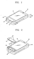
- With reference to
FIG. 1 , amobile terminal 10 includes ahousing 20 having adisplay 15 disposed on a front surface thereof, and acover 30 assembled on thehousing 20 to form the overall exterior (appearance) of the mobile terminal. Thecover 30 has a size and a shape for constituting a front surface of themobile terminal 10 together with thedisplay 15. - Preferably, the
display 15 is formed as a mirror in order to reflect light when thedisplay 15 is turned off. Namely, an external window of thedisplay 15 is made of a partially reflective material to allow an internal light to pass therethrough and reflect light coming from outside so that a user can use thedisplay 15 as the mirror when thedisplay 15 is in an OFF state. - The
housing 20 includes anupper housing 21 and alower housing 22 assembled to theupper housing 21. In addition, thehousing 20 may include additional members. - As shown in
FIG. 2 ,input switches 40 are disposed within thecover 30, and thecover 30 is installed to be deformable or movable to press theinput switches 40. Accordingly, when thecover 30 is pressed, it is self-deformed or moved in a direction of to press theinput switches 40. With reference toFIG. 4 , thecover 30 is disposed to be movable and deformable in a pressing direction in a state that it is caught at thehousing 20 by stoppingportion 35 formed at an edge portion of thecover 30. - While
cover 30 has been called a cover, it is not so limited to just a cover, rather it can also be take the form of a casing, case, or frame and may also be shaped into a plate, a panel, a bracket, a band, or a strip. - As shown in
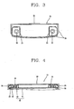
FIG. 4 , the input switches 40 installed within thecover 30 are located on acircuitry supporting substrate 41 having a certain contact pattern and eachinput switch 40 is formed as ametallic dome 42 installed on the contact pattern such that it can be elastically deformable to contact the contact pattern. As thecircuitry supporting substrate 41, a rigid or flexible board can be used, and a fixing sheet (not shown) can be additionally attached on an upper surface of themetallic dome 42 and thecircuit board 41 to maintain the state that themetallic dome 42 is fixed on the contact pattern. - The
cover 30 can be made of a thin metallic plate material with certain strength, andlight transmission openings 31 are formed to indicate where the input switches 40 are positioned beneath thecover 30. A stoppingportion 35 is formed at an edge portion of thecover 30. The stoppingportion 35 extends in a direction away from the front surface of the mobile terminal from an edge portion of thecover 30 and then outwards to engage an interior surface of thehousing 20. Accordingly, because the stoppingportion 35 allows thecover 30 to be caught by thehousing 20, without being exposed, the exterior of the mobile terminal can be formed fine and smooth. - As shown in
FIGS. 3 and 4 , pressingprotrusions 32 extend toward themetallic domes 42 and are attached within thelight transmission openings 31 so that when thecover 30 is pressed by a finger of a user, the input switches 40 can be easily pressed. Thepressing protrusions 32 can be attached on thecover 30 by means of an adhesive or in a mating manner. Alternatively, thepressing protrusions 32 can be integrally injection-molded with the cover. - With reference to
FIGS. 2 and4 ,light emitters 45 are provided at one side of each of the input switches 40 to provide light to outside through thelight transmission openings 31. Preferably, thelight emitters 45 are formed as an element to be mounted on thecircuit board 41. As thelight emitters 45, light emitting diodes (LEDs) or semiconductor lasers can be used. Thepressing protrusions 32 are made of a light transmissive material to allow light to pass therethrough so as to be viewable outside the mobile terminal. - As shown in
FIGS. 3 and 4 , shields 33 made of a light non-transmissive material are formed near thepressing protrusions 32 to prevent a light leakage from thelight emitters 45. Either thepressing protrusions 32 or theshields 33 alone, or in combination, can form a light constraining member to direct light from thelight emitter 45 towards thelight transmission opening 31 and to minimize light emitted from thelight emitter 45 from being directed peripherally of thelight transmission opening 32. In this manner, the light from thelight emitter 45 can be more efficiently utilized. Preferably, the pressingprotrusion 32 andadjacent shield 33 can be formed as a unitary member out of a silicone material. - The
shields 33 have a size that can push thecover 30 in an outward direction so that the stoppingportions 35 of thecover 30 can be maintained in a state of being elastically engaging thehousing 20. Accordingly, when thecover 30 is not pressed from the exterior, thecover 30 is maintained to be pressed against thehousing 20 by elasticity of theshields 33. Thepressing protrusions 32 can also assist in pressing thecover 30 against thehousing 20. - With such a structure, as shown in
FIG. 1 , thecover 30 is assembled with thehousing 20 to form the overall exterior of themobile terminal 10, and as shown inFIG. 4 , when a particular portion of thecover 30 is pressed, the correspondinginput switch 40 is pressed to perform an inputting operation. Accordingly, there is no need to use a device having a plurality of buttons, and thus, the exterior of themobile terminal 10 can be aesthetically improved as well as reducing the number of components. - With reference to
FIG. 5 , amobile terminal 110 according to a second exemplary embodiment of the present invention includes afirst body 111 including a firstkey input unit 112 having a plurality of buttons formed on a surface that is exposed when themobile terminal 110 is in an open position, and asecond body 113 slidably movable to be opened and closed with respect to thefirst body 111. - As shown in
FIG. 6 , thesecond body 113 includes ahousing 120 with adisplay 115 disposed on its upper surface, and acover 130 combined with thehousing 120 to form the exterior of themobile terminal 110. - A
light transmission opening 136 is formed at the central portion of thecover 130, through which a secondkey input unit 150 includingpressing buttons scroll button 153 can pass so as to be mounted in thesecond body 113. - Namely, surrounding the second
key input unit 150, thecover 130 can form an exterior of the housing and also perform an input function independent of the secondkey input unit 150. Stopping portions 135 are similar to stopping portions 25 described above. - Input switches 140,
light emitters 145, and light constraining members located within thecover 130 have the same construction and operation as those in the first exemplary embodiment of the present invention, so a description therefore will be omitted. These elements are also the same in the third to fifth exemplary embodiments of the present invention and the light constraining members have not been shown for clarity. - In the third exemplary embodiment of the present invention, a
cover 230 of amobile terminal 210 has a size and a shape constituting a front surface of themobile terminal 210, and thehousing 220 forms the other remaining exterior of themobile terminal 210. A throughhole 237 is formed at the central portion of thecover 230, on which adisplay 215 is disposed, so that thecover 230 surrounds thedisplay 215 and presses input switches 240 mounted at corner positions (indicated by dotted line arrows inFIG. 8 ) within thecover 230.Light transmission openings 231 are formed in the corner positions of thecover 230 above the input switches 240. Stoppingportions 235 are similar to stopping portions 25 described above. - In a
mobile terminal 310 according to the fourth exemplary embodiment of the present invention, acover 330 is formed as a one body at least partially including two adjacent surfaces of themobile terminal 310. Each of the adjacent surfaces includes alight transmission opening 331 andinput switch 340 associate therewith. Stoppingportions 335 are similar to stopping portions 25 described above. - Accordingly, as indicated by dotted line arrows, the
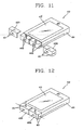
cover 330 can be pressed in at least two directions to performing inputting. - In the fifth exemplary embodiment of the present invention, the cover is formed as two
cover portions cover portions cover 330 can be pressed in the three directions as indicated by the dotted line arrows inFIG. 12 to perform an inputting operation.Light transmission openings 431 are provided on the adjacent surfaces, each being associated with corresponding input switches 440A and 440B. Stopping portions 435 are similar to stopping portions 25 described above. - Accordingly the present invention provides the following effects and advantages.
- Because the cover forming the exterior of the mobile terminal is installed to be deformable or movable to press the input switches disposed within the housing, the cover can replace a general key input unit that has many different contours, and thus, the exterior of the mobile terminal can be aesthetically enhanced.
- Because the pressable cover can surround the display or an additional key input unit and can be integrally formed including two adjacent surfaces of the mobile terminal, inputting operations can be performed in various directions and positions.
- The invention thus being described, it will be obvious that the same may be varied in many ways. Such variations are not to be regarded as a departure from the spirit and scope of the invention, and all such modifications as would be obvious to one skilled in the art are intended to be included within the scope of the following claims.
Claims (3)
- A mobile terminal comprising:a housing (20, 120, 220, 320, 420) having an opening formed therein;a cover (30, 130, 230, 330, 430) disposed in the opening of the housing, the cover including at least one light transmission opening, wherein the cover is a metallic plate;an input switch (40, 140, 240, 340, 440) located beneath the at least one light transmission opening, wherein the input switch is located above a circuitry supporting substrate having contact patterns, the input switch being a metallic dome that is elastically deformable to contact the contact patterns when the cover is pressed;a pressing protrusion (32) attached at an inner side of the cover to cover the at least one light transmission opening and extended toward the input switch, wherein the pressing protrusion is made of light transmissive material;a light emitter (45) configured to illuminate the at least one light transmission opening, wherein the light emitter (45) is located adjacent the metallic dome; anda shield (33) made of a light non-transmissive material, the shield (33) configured to direct light from the light emitter (45) towards the at least one light transmission opening to minimize light emitted from the light emitter from being directed peripherally of the at least one light transmission opening, wherein the shield (33) is provided near the pressing protrusion (32), andwherein the cover and the housing form an exterior of the mobile terminal.
- The mobile terminal according to claim 1, wherein the shield is a unitary member.
- The mobile terminal according to claim 1, wherein the shield is formed of silicone.
Applications Claiming Priority (1)
| Application Number | Priority Date | Filing Date | Title |
|---|---|---|---|
| KR1020060101549A KR101243669B1 (en) | 2006-10-18 | 2006-10-18 | Mobile terminal |
Publications (3)
| Publication Number | Publication Date |
|---|---|
| EP1914964A2 EP1914964A2 (en) | 2008-04-23 |
| EP1914964A3 EP1914964A3 (en) | 2012-06-13 |
| EP1914964B1 true EP1914964B1 (en) | 2015-03-04 |
Family
ID=38961976
Family Applications (1)
| Application Number | Title | Priority Date | Filing Date |
|---|---|---|---|
| EP07001199.4A Not-in-force EP1914964B1 (en) | 2006-10-18 | 2007-01-19 | Mobile terminal comprising a replaceable keypad cover |
Country Status (9)
| Country | Link |
|---|---|
| US (1) | US7826806B2 (en) |
| EP (1) | EP1914964B1 (en) |
| JP (1) | JP5100214B2 (en) |
| KR (1) | KR101243669B1 (en) |
| CN (1) | CN101166201B (en) |
| BR (1) | BRPI0700269A (en) |
| DE (1) | DE102007003268A1 (en) |
| MX (1) | MX2007002081A (en) |
| RU (1) | RU2340112C1 (en) |
Families Citing this family (15)
| Publication number | Priority date | Publication date | Assignee | Title |
|---|---|---|---|---|
| JP5302509B2 (en) * | 2007-01-25 | 2013-10-02 | 日本電気株式会社 | Mobile device |
| CN101599374B (en) * | 2008-06-04 | 2012-11-21 | 鸿富锦精密工业(深圳)有限公司 | Electronic device with panel keys |
| CN101621860A (en) * | 2008-07-04 | 2010-01-06 | 鸿富锦精密工业(深圳)有限公司 | Mobile equipment with full keyboard |
| KR20100027686A (en) | 2008-09-03 | 2010-03-11 | 엘지전자 주식회사 | Mobile terminal and method for controlling the same |
| CN101694593B (en) * | 2009-09-28 | 2012-02-01 | 苏州佳世达电通有限公司 | Portable electronic device |
| ES2717267T3 (en) * | 2011-10-20 | 2019-06-20 | Huawei Tech Co Ltd | Mobile terminal comprising a cover unit with a key mechanism |
| USD734286S1 (en) * | 2014-01-20 | 2015-07-14 | Suzhou Snail Digital Technology Co., Ltd. | Handset |
| USD770999S1 (en) * | 2014-04-22 | 2016-11-08 | Lg Electronics Inc. | Mobile phone |
| USD766862S1 (en) * | 2014-04-22 | 2016-09-20 | Lg Electronics Inc. | Mobile phone |
| USD780708S1 (en) * | 2014-08-22 | 2017-03-07 | Lg Electronics Inc. | Mobile phone |
| CN115257544A (en) * | 2015-03-23 | 2022-11-01 | 株式会社小糸制作所 | Vehicle imaging device, vehicle lamp, and electronic control unit |
| USD810714S1 (en) * | 2015-07-01 | 2018-02-20 | Lg Electronics Inc. | Mobile phone |
| CN109759780B (en) * | 2017-11-10 | 2022-03-22 | 深圳市欢太科技有限公司 | Method for preparing middle frame, middle frame and mobile terminal |
| KR102490516B1 (en) * | 2018-01-19 | 2023-01-20 | 삼성디스플레이 주식회사 | Display device |
| USD947548S1 (en) * | 2019-03-06 | 2022-04-05 | Beijing Xiaomi Mobile Software Co., Ltd. | Mobile phone |
Family Cites Families (67)
| Publication number | Priority date | Publication date | Assignee | Title |
|---|---|---|---|---|
| FR1557783A (en) * | 1967-12-13 | 1969-02-21 | ||
| US3811025A (en) * | 1973-05-17 | 1974-05-14 | Lockheed Electronics Co | Touch panel switch assembly |
| JPS5686723U (en) * | 1979-12-07 | 1981-07-11 | ||
| US4262182A (en) * | 1980-01-11 | 1981-04-14 | General Electric Company | Fully illuminated backlit membrane touch switch |
| US4419555A (en) * | 1982-06-01 | 1983-12-06 | Wilco Corporation | Illuminated push-button switch assembly |
| US4543563A (en) * | 1982-08-23 | 1985-09-24 | Rca Corporation | Mechanically-actuated transparent touchbars and touchplates |
| US4491692A (en) * | 1982-11-05 | 1985-01-01 | Lee Shan S | Light-emitting device mounted under keybuttons of a keyboard |
| DE9000828U1 (en) | 1990-01-25 | 1990-03-29 | Siemens Ag, 1000 Berlin Und 8000 Muenchen, De | |
| US5225818A (en) * | 1990-11-26 | 1993-07-06 | Data Entry Products, Incorporated | Data entry control panel |
| FI88345C (en) * | 1991-01-29 | 1993-04-26 | Nokia Mobile Phones Ltd | BELYST KEYBOARD |
| US5128842A (en) * | 1991-06-03 | 1992-07-07 | Sunarrow Co., Inc. | Uniform illumination plate |
| US5397867A (en) * | 1992-09-04 | 1995-03-14 | Lucas Industries, Inc. | Light distribution for illuminated keyboard switches and displays |
| US5475192A (en) * | 1993-03-15 | 1995-12-12 | Teikoku Tsushin Kogyo Co., Ltd. | Keytop sheet for push-button switches |
| US5401927A (en) * | 1993-03-31 | 1995-03-28 | Motorola, Inc. | Selectively illuminated indicator and method for making the same |
| US5384459A (en) * | 1993-06-01 | 1995-01-24 | Motorola, Inc. | Illuminated switch and keypad assembly having a light gradient and a light conductive elastomeric assembly |
| US5491313A (en) * | 1994-07-22 | 1996-02-13 | General Motors Corporation | Halo lighting for keypad switch assemblies |
| JP3103833B2 (en) * | 1994-08-10 | 2000-10-30 | 信越ポリマー株式会社 | Illuminated pushbutton switch device |
| US5975711A (en) * | 1995-06-27 | 1999-11-02 | Lumitex, Inc. | Integrated display panel assemblies |
| JPH0935571A (en) * | 1995-07-14 | 1997-02-07 | Matsushita Electric Ind Co Ltd | Lighted switch unit |
| JPH0950728A (en) * | 1995-08-07 | 1997-02-18 | Fuji Polymertech Kk | Illuminated switch |
| US5661279A (en) * | 1995-10-26 | 1997-08-26 | Sunarrow Co., Ltd. | Pushbutton switch |
| DE19715053A1 (en) | 1997-04-11 | 1998-10-15 | Bosch Gmbh Robert | Electric device |
| US5847336A (en) * | 1997-05-02 | 1998-12-08 | Telefonaktiebolaget L M Ericsson (Publ) | Direct keypad backlighting |
| SE517491C2 (en) | 1997-06-06 | 2002-06-11 | Ericsson Telefon Ab L M | Mobile Phone Device |
| DE19815014C2 (en) * | 1998-04-03 | 2002-02-14 | Bosch Gmbh Robert | telecommunication terminal |
| JP2000299719A (en) * | 1999-04-12 | 2000-10-24 | Nichinan:Kk | Portable telephone |
| IT246993Y1 (en) * | 1999-08-11 | 2002-05-02 | Telital Spa | NAVIGATION COMMAND FOR MOBILE PHONE |
| JP2001119454A (en) | 1999-10-19 | 2001-04-27 | Matsushita Electric Ind Co Ltd | Portable telephone set |
| JP4282184B2 (en) * | 1999-10-26 | 2009-06-17 | パナソニック株式会社 | Key button illumination device and wireless communication terminal device with key button illumination device |
| FI108582B (en) * | 2000-05-02 | 2002-02-15 | Nokia Corp | Keyboard lighting arrangements that allow dynamic and individual lighting of keys, as well as method of utilizing it |
| FI108901B (en) * | 2000-06-26 | 2002-04-15 | Nokia Corp | Touch-sensitive electromechanical data input mechanism |
| DE60142101D1 (en) * | 2000-08-11 | 2010-06-24 | Alps Electric Co Ltd | Input device with key input operation and coordinate input operation |
| US6704004B1 (en) * | 2000-08-17 | 2004-03-09 | Nokia Mobile Phones Ltd. | Arrangement for integration of key illumination into keymat of portable electronic devices |
| US6803903B1 (en) * | 2000-08-17 | 2004-10-12 | Nokia Mobile Phones, Ltd. | Integration of organic light-emitting components into the keyboard of an electronic device |
| JP5036103B2 (en) * | 2001-05-14 | 2012-09-26 | 日本電気株式会社 | Portable communication device |
| KR100384993B1 (en) * | 2001-05-22 | 2003-05-23 | 주식회사 유일전자 | One body type keypad for having electro luminescent lamp |
| JP2002374339A (en) * | 2001-06-15 | 2002-12-26 | Matsushita Electric Ind Co Ltd | Electronic apparatus |
| JP4295468B2 (en) * | 2001-12-21 | 2009-07-15 | ポリマテック株式会社 | Cover member for illuminated pushbutton switch |
| US6926418B2 (en) * | 2002-04-24 | 2005-08-09 | Nokia Corporation | Integrated light-guide and dome-sheet for keyboard illumination |
| JP2004023651A (en) * | 2002-06-19 | 2004-01-22 | Matsushita Electric Ind Co Ltd | Telephone set |
| JP4172968B2 (en) * | 2002-08-19 | 2008-10-29 | ソニー株式会社 | Mobile terminal device |
| US20040080682A1 (en) * | 2002-10-29 | 2004-04-29 | Dalton Dan L. | Apparatus and method for an improved electronic display |
| US20040204196A1 (en) * | 2002-12-05 | 2004-10-14 | Lester Dunican | Cellular telephone lighting system and method |
| DE10260297A1 (en) | 2002-12-20 | 2004-07-01 | Siemens Ag | Display device for an electrical device |
| KR100938055B1 (en) * | 2003-03-21 | 2010-01-21 | 삼성전자주식회사 | Key inputting device for portable communication device |
| TW559327U (en) * | 2003-03-21 | 2003-10-21 | Hon Hai Prec Ind Co Ltd | Side key assembly |
| US7053799B2 (en) * | 2003-08-28 | 2006-05-30 | Motorola, Inc. | Keypad with illumination structure |
| US7181251B2 (en) * | 2003-10-22 | 2007-02-20 | Nokia Corporation | Mobile communication terminal with multi orientation user interface |
| JP2005150034A (en) * | 2003-11-19 | 2005-06-09 | Mitsumi Electric Co Ltd | Switch unit |
| KR100631670B1 (en) | 2003-12-09 | 2006-10-09 | 엘지전자 주식회사 | Portable terminal |
| TWI231693B (en) * | 2004-01-12 | 2005-04-21 | Asustek Comp Inc | Translucent key structure and its manufacturing method |
| JP2005260294A (en) * | 2004-03-09 | 2005-09-22 | Nec Corp | Illumination apparatus for mobile communication terminal |
| JP2006060334A (en) * | 2004-08-17 | 2006-03-02 | Nec Saitama Ltd | Key button structure and mobile terminal equipment with the same |
| KR100690726B1 (en) | 2004-09-14 | 2007-03-09 | 엘지전자 주식회사 | Mobile phone capable of multitasking and control method thereof |
| KR20070089934A (en) | 2004-12-28 | 2007-09-04 | 선아로 가부시키가이샤 | Thin key sheet and thin key unit incorporating the thin key sheet |
| JP4473752B2 (en) * | 2005-03-04 | 2010-06-02 | ポリマテック株式会社 | Cover sheet for pushbutton switch |
| JP4533786B2 (en) * | 2005-04-08 | 2010-09-01 | 株式会社ケンウッド | Button waterproof structure |
| US7005595B1 (en) * | 2005-04-25 | 2006-02-28 | Unitel Rubber Corporation | Light emitting keypad assembly |
| KR100692742B1 (en) * | 2005-05-13 | 2007-03-09 | 삼성전자주식회사 | Keypad having light guide layer and keypad assembly |
| ES2390653T3 (en) * | 2005-05-19 | 2012-11-15 | Samsung Electronics Co., Ltd. | Keyboard and keyboard set |
| KR100689392B1 (en) * | 2005-05-19 | 2007-03-02 | 삼성전자주식회사 | Key-pad and key-pad assembly using the same |
| KR100689394B1 (en) * | 2005-06-28 | 2007-03-02 | 삼성전자주식회사 | Keypad assembly for mobile phone |
| KR100689395B1 (en) * | 2005-07-06 | 2007-03-02 | 삼성전자주식회사 | Key pad assembly |
| KR100651413B1 (en) * | 2005-07-15 | 2006-11-29 | 삼성전자주식회사 | Key pad assembly |
| KR100652755B1 (en) * | 2005-08-30 | 2006-12-01 | 엘지전자 주식회사 | Portable phone of a touching and pushing type able to be backlighted |
| KR100754587B1 (en) * | 2006-03-03 | 2007-09-05 | 삼성전자주식회사 | Keypad assembly for electronic equipment |
| KR200426164Y1 (en) | 2006-06-22 | 2006-09-08 | 박선근 | Input Member for Mobile Device |
-
2006
- 2006-10-18 KR KR1020060101549A patent/KR101243669B1/en not_active IP Right Cessation
-
2007
- 2007-01-05 US US11/649,850 patent/US7826806B2/en not_active Expired - Fee Related
- 2007-01-19 EP EP07001199.4A patent/EP1914964B1/en not_active Not-in-force
- 2007-01-23 DE DE102007003268A patent/DE102007003268A1/en not_active Withdrawn
- 2007-02-14 BR BRPI0700269-6A patent/BRPI0700269A/en not_active Application Discontinuation
- 2007-02-20 MX MX2007002081A patent/MX2007002081A/en active IP Right Grant
- 2007-02-27 RU RU2007107412/09A patent/RU2340112C1/en not_active IP Right Cessation
- 2007-02-27 CN CN2007100843036A patent/CN101166201B/en not_active Expired - Fee Related
- 2007-06-19 JP JP2007161667A patent/JP5100214B2/en not_active Expired - Fee Related
Also Published As
| Publication number | Publication date |
|---|---|
| US7826806B2 (en) | 2010-11-02 |
| KR101243669B1 (en) | 2013-03-25 |
| EP1914964A3 (en) | 2012-06-13 |
| RU2007107412A (en) | 2008-09-10 |
| JP2008104145A (en) | 2008-05-01 |
| EP1914964A2 (en) | 2008-04-23 |
| CN101166201A (en) | 2008-04-23 |
| DE102007003268A1 (en) | 2008-04-24 |
| BRPI0700269A (en) | 2008-06-03 |
| CN101166201B (en) | 2011-09-07 |
| KR20080035202A (en) | 2008-04-23 |
| JP5100214B2 (en) | 2012-12-19 |
| US20080096616A1 (en) | 2008-04-24 |
| RU2340112C1 (en) | 2008-11-27 |
| MX2007002081A (en) | 2008-11-18 |
Similar Documents
| Publication | Publication Date | Title |
|---|---|---|
| EP1914964B1 (en) | Mobile terminal comprising a replaceable keypad cover | |
| KR101228452B1 (en) | Keypad assembly and mobile terminal having it | |
| CA2473331C (en) | Cover plate for a mobile device having a push-through dial keypad | |
| US9239591B2 (en) | Case for a hand held device | |
| JP4485103B2 (en) | Mobile terminal device | |
| JP2006060334A (en) | Key button structure and mobile terminal equipment with the same | |
| JP2007068173A (en) | Touch key assembly and mobile communication terminal having same | |
| US9142369B2 (en) | Stack assembly for implementing keypads on mobile computing devices | |
| KR20090057270A (en) | Electronic device | |
| JP2010108749A (en) | Portable electronic apparatus | |
| JP2007073445A (en) | Key operation part and electronic equipment | |
| CA2765693C (en) | Electronic mobile device seamless key/display structure | |
| CA2765689C (en) | Electronic mobile device seamless key/display structure | |
| US9092192B2 (en) | Electronic mobile device seamless key/display structure | |
| US8362372B2 (en) | Electronic mobile device seamless key/display structure | |
| JP2012079472A (en) | Input device member | |
| JP2006042215A (en) | Portable electronic apparatus | |
| JP2003060755A (en) | Portable terminal device | |
| JP2008166993A (en) | Electronic instrument | |
| JP2005209500A (en) | Push-button switching cover and electronic equipment |
Legal Events
| Date | Code | Title | Description |
|---|---|---|---|
| PUAI | Public reference made under article 153(3) epc to a published international application that has entered the european phase |
Free format text: ORIGINAL CODE: 0009012 |
|
| AK | Designated contracting states |
Kind code of ref document: A2 Designated state(s): AT BE BG CH CY CZ DE DK EE ES FI FR GB GR HU IE IS IT LI LT LU LV MC NL PL PT RO SE SI SK TR |
|
| AX | Request for extension of the european patent |
Extension state: AL BA HR MK RS |
|
| RIC1 | Information provided on ipc code assigned before grant |
Ipc: H01H 25/00 20060101ALI20120126BHEP Ipc: H04M 1/23 20060101ALI20120126BHEP Ipc: H04M 1/02 20060101ALI20120126BHEP Ipc: H01H 9/18 20060101ALI20120126BHEP Ipc: H04M 1/22 20060101AFI20120126BHEP Ipc: H01H 13/83 20060101ALI20120126BHEP Ipc: H01H 25/04 20060101ALI20120126BHEP |
|
| PUAL | Search report despatched |
Free format text: ORIGINAL CODE: 0009013 |
|
| AK | Designated contracting states |
Kind code of ref document: A3 Designated state(s): AT BE BG CH CY CZ DE DK EE ES FI FR GB GR HU IE IS IT LI LT LU LV MC NL PL PT RO SE SI SK TR |
|
| AX | Request for extension of the european patent |
Extension state: AL BA HR MK RS |
|
| RIC1 | Information provided on ipc code assigned before grant |
Ipc: H01H 25/00 20060101ALI20120504BHEP Ipc: H04M 1/02 20060101ALI20120504BHEP Ipc: H01H 25/04 20060101ALI20120504BHEP Ipc: H01H 9/18 20060101ALI20120504BHEP Ipc: H04M 1/22 20060101AFI20120504BHEP Ipc: H04M 1/23 20060101ALI20120504BHEP Ipc: H01H 13/83 20060101ALI20120504BHEP |
|
| 17P | Request for examination filed |
Effective date: 20121120 |
|
| 17Q | First examination report despatched |
Effective date: 20130114 |
|
| AKX | Designation fees paid |
Designated state(s): AT BE BG CH CY CZ DE DK EE ES FI FR GB GR HU IE IS IT LI LT LU LV MC NL PL PT RO SE SI SK TR |
|
| GRAP | Despatch of communication of intention to grant a patent |
Free format text: ORIGINAL CODE: EPIDOSNIGR1 |
|
| INTG | Intention to grant announced |
Effective date: 20140820 |
|
| GRAS | Grant fee paid |
Free format text: ORIGINAL CODE: EPIDOSNIGR3 |
|
| GRAP | Despatch of communication of intention to grant a patent |
Free format text: ORIGINAL CODE: EPIDOSNIGR1 |
|
| INTG | Intention to grant announced |
Effective date: 20150109 |
|
| RAP1 | Party data changed (applicant data changed or rights of an application transferred) |
Owner name: LG ELECTRONICS INC. |
|
| GRAA | (expected) grant |
Free format text: ORIGINAL CODE: 0009210 |
|
| AK | Designated contracting states |
Kind code of ref document: B1 Designated state(s): AT BE BG CH CY CZ DE DK EE ES FI FR GB GR HU IE IS IT LI LT LU LV MC NL PL PT RO SE SI SK TR |
|
| REG | Reference to a national code |
Ref country code: GB Ref legal event code: FG4D |
|
| REG | Reference to a national code |
Ref country code: CH Ref legal event code: EP |
|
| REG | Reference to a national code |
Ref country code: IE Ref legal event code: FG4D |
|
| REG | Reference to a national code |
Ref country code: AT Ref legal event code: REF Ref document number: 714710 Country of ref document: AT Kind code of ref document: T Effective date: 20150415 |
|
| REG | Reference to a national code |
Ref country code: DE Ref legal event code: R096 Ref document number: 602007040439 Country of ref document: DE Effective date: 20150416 |
|
| REG | Reference to a national code |
Ref country code: AT Ref legal event code: MK05 Ref document number: 714710 Country of ref document: AT Kind code of ref document: T Effective date: 20150304 Ref country code: NL Ref legal event code: VDEP Effective date: 20150304 |
|
| PG25 | Lapsed in a contracting state [announced via postgrant information from national office to epo] |
Ref country code: LT Free format text: LAPSE BECAUSE OF FAILURE TO SUBMIT A TRANSLATION OF THE DESCRIPTION OR TO PAY THE FEE WITHIN THE PRESCRIBED TIME-LIMIT Effective date: 20150304 Ref country code: ES Free format text: LAPSE BECAUSE OF FAILURE TO SUBMIT A TRANSLATION OF THE DESCRIPTION OR TO PAY THE FEE WITHIN THE PRESCRIBED TIME-LIMIT Effective date: 20150304 Ref country code: FI Free format text: LAPSE BECAUSE OF FAILURE TO SUBMIT A TRANSLATION OF THE DESCRIPTION OR TO PAY THE FEE WITHIN THE PRESCRIBED TIME-LIMIT Effective date: 20150304 Ref country code: SE Free format text: LAPSE BECAUSE OF FAILURE TO SUBMIT A TRANSLATION OF THE DESCRIPTION OR TO PAY THE FEE WITHIN THE PRESCRIBED TIME-LIMIT Effective date: 20150304 |
|
| REG | Reference to a national code |
Ref country code: LT Ref legal event code: MG4D |
|
| PG25 | Lapsed in a contracting state [announced via postgrant information from national office to epo] |
Ref country code: LV Free format text: LAPSE BECAUSE OF FAILURE TO SUBMIT A TRANSLATION OF THE DESCRIPTION OR TO PAY THE FEE WITHIN THE PRESCRIBED TIME-LIMIT Effective date: 20150304 Ref country code: AT Free format text: LAPSE BECAUSE OF FAILURE TO SUBMIT A TRANSLATION OF THE DESCRIPTION OR TO PAY THE FEE WITHIN THE PRESCRIBED TIME-LIMIT Effective date: 20150304 Ref country code: GR Free format text: LAPSE BECAUSE OF FAILURE TO SUBMIT A TRANSLATION OF THE DESCRIPTION OR TO PAY THE FEE WITHIN THE PRESCRIBED TIME-LIMIT Effective date: 20150605 |
|
| PG25 | Lapsed in a contracting state [announced via postgrant information from national office to epo] |
Ref country code: NL Free format text: LAPSE BECAUSE OF FAILURE TO SUBMIT A TRANSLATION OF THE DESCRIPTION OR TO PAY THE FEE WITHIN THE PRESCRIBED TIME-LIMIT Effective date: 20150304 |
|
| PG25 | Lapsed in a contracting state [announced via postgrant information from national office to epo] |
Ref country code: CZ Free format text: LAPSE BECAUSE OF FAILURE TO SUBMIT A TRANSLATION OF THE DESCRIPTION OR TO PAY THE FEE WITHIN THE PRESCRIBED TIME-LIMIT Effective date: 20150304 Ref country code: PT Free format text: LAPSE BECAUSE OF FAILURE TO SUBMIT A TRANSLATION OF THE DESCRIPTION OR TO PAY THE FEE WITHIN THE PRESCRIBED TIME-LIMIT Effective date: 20150706 Ref country code: SK Free format text: LAPSE BECAUSE OF FAILURE TO SUBMIT A TRANSLATION OF THE DESCRIPTION OR TO PAY THE FEE WITHIN THE PRESCRIBED TIME-LIMIT Effective date: 20150304 Ref country code: EE Free format text: LAPSE BECAUSE OF FAILURE TO SUBMIT A TRANSLATION OF THE DESCRIPTION OR TO PAY THE FEE WITHIN THE PRESCRIBED TIME-LIMIT Effective date: 20150304 Ref country code: RO Free format text: LAPSE BECAUSE OF FAILURE TO SUBMIT A TRANSLATION OF THE DESCRIPTION OR TO PAY THE FEE WITHIN THE PRESCRIBED TIME-LIMIT Effective date: 20150304 |
|
| PG25 | Lapsed in a contracting state [announced via postgrant information from national office to epo] |
Ref country code: IS Free format text: LAPSE BECAUSE OF FAILURE TO SUBMIT A TRANSLATION OF THE DESCRIPTION OR TO PAY THE FEE WITHIN THE PRESCRIBED TIME-LIMIT Effective date: 20150704 Ref country code: PL Free format text: LAPSE BECAUSE OF FAILURE TO SUBMIT A TRANSLATION OF THE DESCRIPTION OR TO PAY THE FEE WITHIN THE PRESCRIBED TIME-LIMIT Effective date: 20150304 |
|
| REG | Reference to a national code |
Ref country code: DE Ref legal event code: R097 Ref document number: 602007040439 Country of ref document: DE |
|
| REG | Reference to a national code |
Ref country code: FR Ref legal event code: PLFP Year of fee payment: 10 |
|
| PG25 | Lapsed in a contracting state [announced via postgrant information from national office to epo] |
Ref country code: IT Free format text: LAPSE BECAUSE OF FAILURE TO SUBMIT A TRANSLATION OF THE DESCRIPTION OR TO PAY THE FEE WITHIN THE PRESCRIBED TIME-LIMIT Effective date: 20150304 |
|
| PLBE | No opposition filed within time limit |
Free format text: ORIGINAL CODE: 0009261 |
|
| STAA | Information on the status of an ep patent application or granted ep patent |
Free format text: STATUS: NO OPPOSITION FILED WITHIN TIME LIMIT |
|
| PG25 | Lapsed in a contracting state [announced via postgrant information from national office to epo] |
Ref country code: DK Free format text: LAPSE BECAUSE OF FAILURE TO SUBMIT A TRANSLATION OF THE DESCRIPTION OR TO PAY THE FEE WITHIN THE PRESCRIBED TIME-LIMIT Effective date: 20150304 |
|
| 26N | No opposition filed |
Effective date: 20151207 |
|
| PG25 | Lapsed in a contracting state [announced via postgrant information from national office to epo] |
Ref country code: SI Free format text: LAPSE BECAUSE OF FAILURE TO SUBMIT A TRANSLATION OF THE DESCRIPTION OR TO PAY THE FEE WITHIN THE PRESCRIBED TIME-LIMIT Effective date: 20150304 |
|
| PG25 | Lapsed in a contracting state [announced via postgrant information from national office to epo] |
Ref country code: BE Free format text: LAPSE BECAUSE OF NON-PAYMENT OF DUE FEES Effective date: 20160131 |
|
| PG25 | Lapsed in a contracting state [announced via postgrant information from national office to epo] |
Ref country code: BE Free format text: LAPSE BECAUSE OF FAILURE TO SUBMIT A TRANSLATION OF THE DESCRIPTION OR TO PAY THE FEE WITHIN THE PRESCRIBED TIME-LIMIT Effective date: 20150304 Ref country code: LU Free format text: LAPSE BECAUSE OF FAILURE TO SUBMIT A TRANSLATION OF THE DESCRIPTION OR TO PAY THE FEE WITHIN THE PRESCRIBED TIME-LIMIT Effective date: 20160119 |
|
| REG | Reference to a national code |
Ref country code: CH Ref legal event code: PL |
|
| PG25 | Lapsed in a contracting state [announced via postgrant information from national office to epo] |
Ref country code: MC Free format text: LAPSE BECAUSE OF FAILURE TO SUBMIT A TRANSLATION OF THE DESCRIPTION OR TO PAY THE FEE WITHIN THE PRESCRIBED TIME-LIMIT Effective date: 20150304 |
|
| PG25 | Lapsed in a contracting state [announced via postgrant information from national office to epo] |
Ref country code: LI Free format text: LAPSE BECAUSE OF NON-PAYMENT OF DUE FEES Effective date: 20160131 Ref country code: CH Free format text: LAPSE BECAUSE OF NON-PAYMENT OF DUE FEES Effective date: 20160131 |
|
| REG | Reference to a national code |
Ref country code: IE Ref legal event code: MM4A |
|
| REG | Reference to a national code |
Ref country code: FR Ref legal event code: PLFP Year of fee payment: 11 |
|
| PG25 | Lapsed in a contracting state [announced via postgrant information from national office to epo] |
Ref country code: IE Free format text: LAPSE BECAUSE OF NON-PAYMENT OF DUE FEES Effective date: 20160119 |
|
| PGFP | Annual fee paid to national office [announced via postgrant information from national office to epo] |
Ref country code: GB Payment date: 20161206 Year of fee payment: 11 |
|
| PGFP | Annual fee paid to national office [announced via postgrant information from national office to epo] |
Ref country code: FR Payment date: 20161213 Year of fee payment: 11 |
|
| PGFP | Annual fee paid to national office [announced via postgrant information from national office to epo] |
Ref country code: DE Payment date: 20161205 Year of fee payment: 11 |
|
| PG25 | Lapsed in a contracting state [announced via postgrant information from national office to epo] |
Ref country code: HU Free format text: LAPSE BECAUSE OF FAILURE TO SUBMIT A TRANSLATION OF THE DESCRIPTION OR TO PAY THE FEE WITHIN THE PRESCRIBED TIME-LIMIT; INVALID AB INITIO Effective date: 20070119 Ref country code: CY Free format text: LAPSE BECAUSE OF FAILURE TO SUBMIT A TRANSLATION OF THE DESCRIPTION OR TO PAY THE FEE WITHIN THE PRESCRIBED TIME-LIMIT Effective date: 20150304 |
|
| PG25 | Lapsed in a contracting state [announced via postgrant information from national office to epo] |
Ref country code: TR Free format text: LAPSE BECAUSE OF FAILURE TO SUBMIT A TRANSLATION OF THE DESCRIPTION OR TO PAY THE FEE WITHIN THE PRESCRIBED TIME-LIMIT Effective date: 20150304 |
|
| PG25 | Lapsed in a contracting state [announced via postgrant information from national office to epo] |
Ref country code: BG Free format text: LAPSE BECAUSE OF FAILURE TO SUBMIT A TRANSLATION OF THE DESCRIPTION OR TO PAY THE FEE WITHIN THE PRESCRIBED TIME-LIMIT Effective date: 20150304 |
|
| REG | Reference to a national code |
Ref country code: DE Ref legal event code: R119 Ref document number: 602007040439 Country of ref document: DE |
|
| GBPC | Gb: european patent ceased through non-payment of renewal fee |
Effective date: 20180119 |
|
| PG25 | Lapsed in a contracting state [announced via postgrant information from national office to epo] |
Ref country code: FR Free format text: LAPSE BECAUSE OF NON-PAYMENT OF DUE FEES Effective date: 20180131 Ref country code: DE Free format text: LAPSE BECAUSE OF NON-PAYMENT OF DUE FEES Effective date: 20180801 |
|
| REG | Reference to a national code |
Ref country code: FR Ref legal event code: ST Effective date: 20180928 |
|
| PG25 | Lapsed in a contracting state [announced via postgrant information from national office to epo] |
Ref country code: GB Free format text: LAPSE BECAUSE OF NON-PAYMENT OF DUE FEES Effective date: 20180119 |