EP1914911A1 - Method and system for indoor communications with optical distribution - Google Patents
Method and system for indoor communications with optical distribution Download PDFInfo
- Publication number
- EP1914911A1 EP1914911A1 EP06301069A EP06301069A EP1914911A1 EP 1914911 A1 EP1914911 A1 EP 1914911A1 EP 06301069 A EP06301069 A EP 06301069A EP 06301069 A EP06301069 A EP 06301069A EP 1914911 A1 EP1914911 A1 EP 1914911A1
- Authority
- EP
- European Patent Office
- Prior art keywords
- optical
- signal
- signals
- sub
- optical sub
- Prior art date
- Legal status (The legal status is an assumption and is not a legal conclusion. Google has not performed a legal analysis and makes no representation as to the accuracy of the status listed.)
- Granted
Links
- 230000003287 optical effect Effects 0.000 title claims abstract description 110
- 238000004891 communication Methods 0.000 title claims abstract description 28
- 238000000034 method Methods 0.000 title claims abstract description 12
- 230000005540 biological transmission Effects 0.000 claims abstract description 22
- 230000001934 delay Effects 0.000 claims abstract description 9
- 230000000694 effects Effects 0.000 description 7
- 230000008901 benefit Effects 0.000 description 3
- 239000013307 optical fiber Substances 0.000 description 2
- 230000004913 activation Effects 0.000 description 1
- 230000001413 cellular effect Effects 0.000 description 1
- 238000005516 engineering process Methods 0.000 description 1
- 230000000644 propagated effect Effects 0.000 description 1
- 230000008054 signal transmission Effects 0.000 description 1
Images


Classifications
-
- H—ELECTRICITY
- H04—ELECTRIC COMMUNICATION TECHNIQUE
- H04B—TRANSMISSION
- H04B1/00—Details of transmission systems, not covered by a single one of groups H04B3/00 - H04B13/00; Details of transmission systems not characterised by the medium used for transmission
- H04B1/69—Spread spectrum techniques
- H04B1/707—Spread spectrum techniques using direct sequence modulation
- H04B1/7097—Interference-related aspects
- H04B1/711—Interference-related aspects the interference being multi-path interference
- H04B1/7115—Constructive combining of multi-path signals, i.e. RAKE receivers
-
- H—ELECTRICITY
- H04—ELECTRIC COMMUNICATION TECHNIQUE
- H04B—TRANSMISSION
- H04B10/00—Transmission systems employing electromagnetic waves other than radio-waves, e.g. infrared, visible or ultraviolet light, or employing corpuscular radiation, e.g. quantum communication
- H04B10/50—Transmitters
Definitions
- the present invention relates to indoor communication systems, particularly inside buildings and tunnels, comprising an optical distribution network.
- Wireless communications systems are becoming an increasingly widespread phenomenon of modern communications. Since many users place an increasing number of cellular calls within buildings or other confined structures, there is a need to achieve high quality indoor coverage.
- a conventional configuration to extend a wireless communication service e.g. GSM or UMTS, from an outdoor environment to an indoor area is shown in Figure 1 and is characterized by the utilization of a repeater R that is typically located within a building B to retransmit within the building a wireless signal Ws received at an external antenna A1 or retransmit outside the building the wireless signals Ws of mobile stations Ms, e.g. mobile phones, handheld computers and the like, located inside the building B.
- a repeater R that is typically located within a building B to retransmit within the building a wireless signal Ws received at an external antenna A1 or retransmit outside the building the wireless signals Ws of mobile stations Ms, e.g. mobile phones, handheld computers and the like, located inside the building B.
- the outdoor wireless signals are passed along a first connection C1 to the repeater R which forwards the signal along a second connection C2 to a plurality of inter-connected amplifiers Am, the amplifiers amplify the signals which are then transmitted over the in-building antennas A2 to A4.
- the repeater R receives said signals along connection C2 and transmits them along connection C1 to the external antenna A1.
- repeater R of the indoor communications structure is replaced by a base station connected to a communications core network along connection C1.
- Connections C1 and C2 may be a radio frequency (RF) connection or network, e.g. using coaxial cable, an optical connection or network, e.g. using optical fiber, or a high-speed data distribution network such as an Ethernet network, e.g. using a Category 5 cable.
- RF radio frequency
- the in-building antennas A2 to A4 may also be implemented as RF radiating cables, e.g. this is typically the case when the wireless signals shall be propagated in tunnels.
- the object of the present is to provide a method and a system for indoor communications which improves the quality of the wireless indoor service coverage.
- the object is achieved by a method for indoor communications according to claim 1 and/or 2, a multi-path arrangement according to claim 3, a transmitting or receiving unit according to claim 6, an optical network according to claim 7 and an indoor communications system according to claim 8.
- the basic idea behind the invention arises from the observation that in indoor or confined environments the multi-path time delay of the radio signals reaching or transmitted by a mobile station is shorter than the minimum needed for a rake receiver of a mobile station or a base station to work properly i.e. at least one chip length (e.g. 260 ns for UMTS). In such cases then there is no benefit from the technical advantages of the rake receivers, already present in the mobile stations and base stations, in order to achieve improved reception i.e. a rake receiver shows a higher Signal to Noise Ratio (SNR) in a multi-path environment than in an environment without multi-path effects.
- SNR Signal to Noise Ratio
- the method and system for indoor communications according to the invention allows the generation of signals having multi-path time delays of at least one chip length. According to the invention, combining a plurality of substantially identical sub-signals showing different time delays between them of at least one chip length, generates a new signal showing a behavior similar to a radio signal in an outdoor multi-path environment.
- the solution can be applicable for indoor downlink or uplink transmission or both for indoor downlink and uplink transmission.
- signal uplink direction that is from mobile station to the base station
- the rake receiver of the base station receives signals with multi-path delays greater than 1 chip length
- signal downlink direction that is from the base station to the mobile station
- the rake receiver of the mobile station receives signals with multi-path delays greater than 1 chip length
- the solution is preferably adapted for transmission of signals to and from a mobile station located in a confined area, such as a building or a tunnel, using at least an optical transmission network.
- the system for indoor communications comprises an optical network for distribution of signals between a base station and an optical remote unit which provides the signals to an indoor antenna or a radiating cable.
- the optical remote units comprise electro-optical and opto-electrical transmitting or receiving means for transmitting or receiving the optical signals along the optical distribution network.
- the optical network according to the invention is used advantageously to improve the service performance for radio communications into buildings and tunnels which do not provide system conditions sufficient to benefit from the rake receivers of mobile stations or base stations using, for example, CDMA or UMTS communication technology.
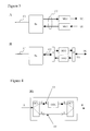
- Figure 1 shows a conventional indoor communications system structure.
- Figure 2 shows an example structure of an indoor communications system according to the invention.
- FIGS 3 A, B show exemplary details of an indoor communications system according to the invention.
- Figure 4 shows a multi-path arrangement according to the invention.
- FIG. 2 An example of an indoor communications system structure according to the invention, located in a building B, is shown in Figure 2, comprising a base station Bs, a master unit Mu, a multi-path arrangement MA, interface connections I1 and i2, an optical network C2, three optical remote units RU and three in-building antennas A2 to A4.
- the base station Bs is connected to a core network CN along a first connection network C1 and the indoor antennas A2 to A4 send and receive radio signals Ws to/from a mobile station Ms.
- communications core network CN signals intended for the mobile station Ms are received by the base station Bs along connection C1. Said signals are then passed through a first connection interface i1, e.g. an RF or digital interface, to the master unit Mu in charge of adapting the signals received from the base station Bs to optical form and forward them through a second connection interface i2 to the optical network C2 for distribution.
- the optical network comprises the multi-path arrangement MA where the optical signals are split into at least two substantially identical optical sub-signals, a different time delay is applied to each individual optical sub-signal so that the at least two substantially identical optical sub-signals have a time delay difference of at least 1 chip length, and subsequently the optical sub-signals are combined.
- Said combined signals at the output of the multi-path arrangement MA are distributed to the optical remote units RU, which adapt the received optical signal, e.g. with the use of an opto-electrical converter and/or an opto-electrical amplifier, for transmission through the in-building antennas A2 to A4. Since the in-building antennas transmit this new radio signal showing multi-path effects, the performance of rake receivers within the mobile stations of the building is optimized and the quality of reception in such an environment is improved.
- radio signals Ws transmitted by the mobile station Ms located inside the building B are received by the in-building antenna A2 and passed to the optical remote unit RU, which adapts the signals, e.g. with the use of an electro-optical converter and/or an electro-optical amplifier, for transmission through the optical connection C2 to the multi-path arrangement MA.
- said optical signals are split into at least two substantially identical optical sub-signals, a different time delay is applied to each individual optical sub-signal so that the at least two substantially identical optical sub-signals have a time delay difference of at least 1 chip length, and subsequently the optical sub-signals are combined.
- Said combined signals at the output of the multi-path arrangement MA are passed through the second connection interface i2 to the master unit Mu in charge of adapting the signals received from the optical network C2 for transmission through the first connection interface, e.g. RF or digital interface, to the base station Bs.
- the base station provides said signals, in appropriate form, to a rake receiver within the base station which is in charge of processing the multi-path signal components and obtain the transmitted mobile station signal.
- Said signal is then forwarded to the communications core network CN.
- Figure 3A shows a first exemplary detail of an indoor communications system according to the invention comprising a first connections network C1, a base station Bs, an optical network C2 and two multi-path arrangements MA1 and MA2, the first used for downlink transmission DL and the second used for uplink transmission UL.
- Figure 3B shows also another way of using two multi-path arrangements MA1 and MA2 with only one optical line for both downlink DL and uplink transmission UL.
- WDMA wavelength multiplex access
- Figure 4 shows an example of a multi-path arrangement MA according to the invention for an optical network, comprising an optical signal input port A, an optical signal output port B, two optical transmission lines O1 and O2, two optical couplers OC1 and OC2, nodes C,D, E and F, and an optical delay unit ODU.
- the optical signal input A is connected to the first optical coupler OC1 which splits an incoming optical signal in two substantially identical optical sub-signals and outputs them in nodes C and E.
- a first optical transmission line O1 is connected between output node C of the first optical coupler OC1 and input node D of the second optical coupler OC2.
- a second optical transmission line O2 is connected between output node E of the first optical coupler OC1 and input node F of the second optical coupler OC2.
- An optical delay unit ODU is arranged in the first optical transmission line O1.
- the second optical coupler OC2 combines the two incoming optical sub-signals into a single optical signal at output port B.
- the first optical coupler OC1 splits an incoming optical signal that is fed in input port A into two substantially identical sub-signals. Those two optical sub-signals take two different signal paths ACDB and AEFB.
- the signal path ACDB introduces a time delay of at least one chip length, e.g. at least 260 ns for UMTS, to that optical sub-signal.
- the second optical coupler OC2 combines the two sub-signals after passing through their individual signal paths ACDB and AEFB to a new optical output signal showing a behavior similar to a signal in a multi-path environment.
- An incoming signal is then split into a number "n+1" of substantially identical optical sub-signals equal to the number of signal paths. After the sub-signals have passed through their individual signal paths they are combined to a new signal at output port B showing multi-path effects, that is showing a behavior similar to a radio signal received in an outdoor multi-path environment.
- the new combined signal comprises the necessary characteristics needed for the rake receivers present in mobile stations and base stations to demodulate this signal. This enables the activation of the so-called rake effect providing a higher SNR in receivers of node base stations and mobile phones.
- the optical delay unit ODU preferably is an optical fiber of appropriate physical length. It is also possible that the optical delay unit ODU is implemented as being the first optical transmission line O1 with the appropriate physical length.
- the optical delay unit ODU can also be implemented by any other known means and providing a variable and adjustable time delay.
- the multi-path arrangement MA is a reciprocal passive device, its transmission characteristics are identical in both port directions AB - BA. It is also understood that although presented in the figures as a standalone arrangement of the optical transmission network of the indoor communications system said functionality can also be implemented inside the optical repeater or the master unit of the indoor communications system.
Landscapes
- Engineering & Computer Science (AREA)
- Computer Networks & Wireless Communication (AREA)
- Signal Processing (AREA)
- Physics & Mathematics (AREA)
- Electromagnetism (AREA)
- Mobile Radio Communication Systems (AREA)
- Optical Communication System (AREA)
Abstract
Description
- The present invention relates to indoor communication systems, particularly inside buildings and tunnels, comprising an optical distribution network.
- Wireless communications systems are becoming an increasingly widespread phenomenon of modern communications. Since many users place an increasing number of cellular calls within buildings or other confined structures, there is a need to achieve high quality indoor coverage.
- A conventional configuration to extend a wireless communication service e.g. GSM or UMTS, from an outdoor environment to an indoor area is shown in Figure 1 and is characterized by the utilization of a repeater R that is typically located within a building B to retransmit within the building a wireless signal Ws received at an external antenna A1 or retransmit outside the building the wireless signals Ws of mobile stations Ms, e.g. mobile phones, handheld computers and the like, located inside the building B. In the downlink, that is when the wireless signals Ws from the external environment are transmitted to the mobile stations Ms inside the building B, said outdoor wireless signals are passed along a first connection C1 to the repeater R which forwards the signal along a second connection C2 to a plurality of inter-connected amplifiers Am, the amplifiers amplify the signals which are then transmitted over the in-building antennas A2 to A4. In the uplink direction, that is, when the wireless signals Ws from the mobile stations Ms are transmitted to a wireless infrastructure outside the building B, the repeater R receives said signals along connection C2 and transmits them along connection C1 to the external antenna A1.
- It is also possible that the repeater R of the indoor communications structure is replaced by a base station connected to a communications core network along connection C1.
- Connections C1 and C2 may be a radio frequency (RF) connection or network, e.g. using coaxial cable, an optical connection or network, e.g. using optical fiber, or a high-speed data distribution network such as an Ethernet network, e.g. using a Category 5 cable. The in-building antennas A2 to A4 may also be implemented as RF radiating cables, e.g. this is typically the case when the wireless signals shall be propagated in tunnels.
- The object of the present is to provide a method and a system for indoor communications which improves the quality of the wireless indoor service coverage.
- The object is achieved by a method for indoor communications according to claim 1 and/or 2, a multi-path arrangement according to claim 3, a transmitting or receiving unit according to claim 6, an optical network according to claim 7 and an indoor communications system according to claim 8.
- The basic idea behind the invention arises from the observation that in indoor or confined environments the multi-path time delay of the radio signals reaching or transmitted by a mobile station is shorter than the minimum needed for a rake receiver of a mobile station or a base station to work properly i.e. at least one chip length (e.g. 260 ns for UMTS). In such cases then there is no benefit from the technical advantages of the rake receivers, already present in the mobile stations and base stations, in order to achieve improved reception i.e. a rake receiver shows a higher Signal to Noise Ratio (SNR) in a multi-path environment than in an environment without multi-path effects. With the present solution, optimum outdoor multi-path propagation effects are emulated in indoor "clean" environments (locations where the overall differential time delay of radio signals due to multi-path propagation is shorter than 1 chip length). The method and system for indoor communications according to the invention allows the generation of signals having multi-path time delays of at least one chip length. According to the invention, combining a plurality of substantially identical sub-signals showing different time delays between them of at least one chip length, generates a new signal showing a behavior similar to a radio signal in an outdoor multi-path environment.
- The solution can be applicable for indoor downlink or uplink transmission or both for indoor downlink and uplink transmission. For signal uplink direction, that is from mobile station to the base station, it is advantageous that the rake receiver of the base station receives signals with multi-path delays greater than 1 chip length, and for signal downlink direction, that is from the base station to the mobile station, it is advantageous that the rake receiver of the mobile station receives signals with multi-path delays greater than 1 chip length.
- According to the present invention, the solution is preferably adapted for transmission of signals to and from a mobile station located in a confined area, such as a building or a tunnel, using at least an optical transmission network. The system for indoor communications according to the invention comprises an optical network for distribution of signals between a base station and an optical remote unit which provides the signals to an indoor antenna or a radiating cable. The optical remote units comprise electro-optical and opto-electrical transmitting or receiving means for transmitting or receiving the optical signals along the optical distribution network.
- The optical network according to the invention is used advantageously to improve the service performance for radio communications into buildings and tunnels which do not provide system conditions sufficient to benefit from the rake receivers of mobile stations or base stations using, for example, CDMA or UMTS communication technology.
- An embodiment example of the invention is now explained with the aid of Figures 1 to 4.
- Figure 1 shows a conventional indoor communications system structure.
- Figure 2 shows an example structure of an indoor communications system according to the invention.
- Figures 3 A, B show exemplary details of an indoor communications system according to the invention.
- Figure 4 shows a multi-path arrangement according to the invention.
- An example of an indoor communications system structure according to the invention, located in a building B, is shown in Figure 2, comprising a base station Bs, a master unit Mu, a multi-path arrangement MA, interface connections I1 and i2, an optical network C2, three optical remote units RU and three in-building antennas A2 to A4. The base station Bs is connected to a core network CN along a first connection network C1 and the indoor antennas A2 to A4 send and receive radio signals Ws to/from a mobile station Ms.
- In the downlink direction, communications core network CN signals intended for the mobile station Ms are received by the base station Bs along connection C1. Said signals are then passed through a first connection interface i1, e.g. an RF or digital interface, to the master unit Mu in charge of adapting the signals received from the base station Bs to optical form and forward them through a second connection interface i2 to the optical network C2 for distribution. The optical network comprises the multi-path arrangement MA where the optical signals are split into at least two substantially identical optical sub-signals, a different time delay is applied to each individual optical sub-signal so that the at least two substantially identical optical sub-signals have a time delay difference of at least 1 chip length, and subsequently the optical sub-signals are combined. Said combined signals at the output of the multi-path arrangement MA are distributed to the optical remote units RU, which adapt the received optical signal, e.g. with the use of an opto-electrical converter and/or an opto-electrical amplifier, for transmission through the in-building antennas A2 to A4. Since the in-building antennas transmit this new radio signal showing multi-path effects, the performance of rake receivers within the mobile stations of the building is optimized and the quality of reception in such an environment is improved.
- In the uplink direction, radio signals Ws transmitted by the mobile station Ms located inside the building B are received by the in-building antenna A2 and passed to the optical remote unit RU, which adapts the signals, e.g. with the use of an electro-optical converter and/or an electro-optical amplifier, for transmission through the optical connection C2 to the multi-path arrangement MA. According to the invention, in the multi-path arrangement, said optical signals are split into at least two substantially identical optical sub-signals, a different time delay is applied to each individual optical sub-signal so that the at least two substantially identical optical sub-signals have a time delay difference of at least 1 chip length, and subsequently the optical sub-signals are combined. Said combined signals at the output of the multi-path arrangement MA are passed through the second connection interface i2 to the master unit Mu in charge of adapting the signals received from the optical network C2 for transmission through the first connection interface, e.g. RF or digital interface, to the base station Bs. The base station provides said signals, in appropriate form, to a rake receiver within the base station which is in charge of processing the multi-path signal components and obtain the transmitted mobile station signal. Said signal is then forwarded to the communications core network CN. By emulating multi-path effects in the signals received from the mobile stations located in environments that are free of multi-path effects, the performance of the rake receiver within the base station is optimized and the reception performance in uplink direction is improved.
- Figure 3A shows a first exemplary detail of an indoor communications system according to the invention comprising a first connections network C1, a base station Bs, an optical network C2 and two multi-path arrangements MA1 and MA2, the first used for downlink transmission DL and the second used for uplink transmission UL.
- Figure 3B shows also another way of using two multi-path arrangements MA1 and MA2 with only one optical line for both downlink DL and uplink transmission UL. In order to distinguishing the optical uplink signal from the optical downlink signal wavelength multiplex access (WDMA) is applied, and a diplexer D is in charge separating the uplink and downlink optical signals.
- Figure 4 shows an example of a multi-path arrangement MA according to the invention for an optical network, comprising an optical signal input port A, an optical signal output port B, two optical transmission lines O1 and O2, two optical couplers OC1 and OC2, nodes C,D, E and F, and an optical delay unit ODU.
- The optical signal input A is connected to the first optical coupler OC1 which splits an incoming optical signal in two substantially identical optical sub-signals and outputs them in nodes C and E. A first optical transmission line O1 is connected between output node C of the first optical coupler OC1 and input node D of the second optical coupler OC2. A second optical transmission line O2 is connected between output node E of the first optical coupler OC1 and input node F of the second optical coupler OC2. An optical delay unit ODU is arranged in the first optical transmission line O1. The second optical coupler OC2 combines the two incoming optical sub-signals into a single optical signal at output port B.
- The first optical coupler OC1 splits an incoming optical signal that is fed in input port A into two substantially identical sub-signals. Those two optical sub-signals take two different signal paths ACDB and AEFB. The signal path ACDB introduces a time delay of at least one chip length, e.g. at least 260 ns for UMTS, to that optical sub-signal. The second optical coupler OC2 combines the two sub-signals after passing through their individual signal paths ACDB and AEFB to a new optical output signal showing a behavior similar to a signal in a multi-path environment.
- Although Figure 4 shows an arrangement with only two signal paths, it is possible to implement a multi-path arrangement MA comprising more than two signal paths. Then, the preferred condition is that each signal path "n" comprises a time delay of at least a multiple of the chip length ("n x chip length", n = 0,1,2, ...), that is, the individual signal paths provide time delays of zero, one, two, three etc. chip lengths. An incoming signal is then split into a number "n+1" of substantially identical optical sub-signals equal to the number of signal paths. After the sub-signals have passed through their individual signal paths they are combined to a new signal at output port B showing multi-path effects, that is showing a behavior similar to a radio signal received in an outdoor multi-path environment. The new combined signal comprises the necessary characteristics needed for the rake receivers present in mobile stations and base stations to demodulate this signal. This enables the activation of the so-called rake effect providing a higher SNR in receivers of node base stations and mobile phones.
- The optical delay unit ODU preferably is an optical fiber of appropriate physical length. It is also possible that the optical delay unit ODU is implemented as being the first optical transmission line O1 with the appropriate physical length. The optical delay unit ODU can also be implemented by any other known means and providing a variable and adjustable time delay.
- For the sake of generalization, it is understood for a person skilled in the art that since the multi-path arrangement MA is a reciprocal passive device, its transmission characteristics are identical in both port directions AB - BA. It is also understood that although presented in the figures as a standalone arrangement of the optical transmission network of the indoor communications system said functionality can also be implemented inside the optical repeater or the master unit of the indoor communications system.
Claims (8)
- Method for indoor communications, the method comprising
a base station (Bs) receiving a signal intended for a mobile station (Ms) located inside a confined environment (B),
the base station passing said signal to a master unit (Mu) which converts the signal into an optical signal for transmission through an optical network (C2),
the optical network (C2) distributing said optical signal to an optical remote unit (RU), which adapts the optical signal for transmission through a wireless transmission means (A2 to A4),
the mobile station (Ms) receiving the signal transmitted by the wireless transmission means (A2 to A4) and providing said signal to a rake receiver, the method characterized by
in a multi-path arrangement (MA), splitting the optical signal into at least two substantially identical optical sub-signals, applying a different time delay to each individual optical sub-signal so that the time delay difference between the optical sub-signals is at least one chip length, and combining the at least two optical sub-signals with different time delays. - Method for indoor communications, the method comprising
a wireless reception means (A2 to A4) receiving a signal from a mobile station (Ms) located inside a confined environment (B),
the wireless reception means passing the received signal to an optical remote unit (RU) which converts the signal into an optical signal for transmission through an optical network (C2),
the optical network (C2) distributing said optical signal to a master unit (Mu), which adapts the received optical signal for reception by a base station (Bs),
the base station (Bs) providing the received signal to a rake receiver, the method characterized by
in a multi-path arrangement (MA), splitting the optical signal into at least two substantially identical optical sub-signals, applying a different time delay to each individual optical sub-signal so that the time delay difference between the optical sub-signals is at least one chip length, and combining the at least two optical sub-signals with different time delays. - Multi-path arrangement (MA) for an optical network (C2) of an indoor communications system, comprising means for
splitting an incoming optical signal into at least two substantially identical optical sub-signals,
providing each optical sub-signal to a signal path (AEFB, ACDB)
applying a different time delay to each individual optical sub-signal so that the time delay difference between the optical sub-signals is at least one chip length, and
combining the at least two optical sub-signals with different time delays into a single optical output signal. - The multi-path arrangement (MA) of claim 3 wherein the time delay difference between the signal paths (AEFB, ACDB) of the at least two individual optical sub-signals is a multiple of one chip length.
- The multi-path arrangement (MA) of claim 3 wherein at least the first signal path (ACDB) comprises an optical delay unit (ODU).
- A transmitting and/or receiving unit (Mu, RU) comprising a multi-path arrangement (MA) according to any of the claims 3 to 5.
- An optical network (C2) comprising a multi-path arrangement (MA) according to any of the claims 3 to 5.
- An indoor communications system comprising a multi-path arrangement (MA) according to any of the claims 3 to 5.
Priority Applications (3)
| Application Number | Priority Date | Filing Date | Title |
|---|---|---|---|
| AT06301069T ATE438966T1 (en) | 2006-10-20 | 2006-10-20 | INDOOR COMMUNICATION SYSTEM AND METHOD WITH OPTICAL DISTRIBUTION |
| EP06301069A EP1914911B1 (en) | 2006-10-20 | 2006-10-20 | Method and system for indoor communications with optical distribution |
| DE602006008315T DE602006008315D1 (en) | 2006-10-20 | 2006-10-20 | Indoor communication system and optical distribution method |
Applications Claiming Priority (1)
| Application Number | Priority Date | Filing Date | Title |
|---|---|---|---|
| EP06301069A EP1914911B1 (en) | 2006-10-20 | 2006-10-20 | Method and system for indoor communications with optical distribution |
Publications (2)
| Publication Number | Publication Date |
|---|---|
| EP1914911A1 true EP1914911A1 (en) | 2008-04-23 |
| EP1914911B1 EP1914911B1 (en) | 2009-08-05 |
Family
ID=37831436
Family Applications (1)
| Application Number | Title | Priority Date | Filing Date |
|---|---|---|---|
| EP06301069A Active EP1914911B1 (en) | 2006-10-20 | 2006-10-20 | Method and system for indoor communications with optical distribution |
Country Status (3)
| Country | Link |
|---|---|
| EP (1) | EP1914911B1 (en) |
| AT (1) | ATE438966T1 (en) |
| DE (1) | DE602006008315D1 (en) |
Cited By (1)
| Publication number | Priority date | Publication date | Assignee | Title |
|---|---|---|---|---|
| CN107968936A (en) * | 2017-12-29 | 2018-04-27 | 长江勘测规划设计研究有限责任公司 | Web-transporting device applied to underground workshop |
Citations (5)
| Publication number | Priority date | Publication date | Assignee | Title |
|---|---|---|---|---|
| EP0782275A2 (en) * | 1995-12-28 | 1997-07-02 | Nec Corporation | Method and apparatus for eliminating interference using transmission delay and code multiplexing in digital radio system |
| US6075808A (en) * | 1995-03-22 | 2000-06-13 | Nec Corporation | Spread spectrum time diversity communications system |
| US20020118665A1 (en) * | 2000-12-28 | 2002-08-29 | Cleveland Joseph R. | System and method for combining signals at multiple base station receivers |
| EP1482662A1 (en) * | 2003-05-30 | 2004-12-01 | Lucent Technologies Inc. | System and method for alternate mark inversion and duobinary optical transmission |
| US20060233111A1 (en) * | 2005-04-12 | 2006-10-19 | Azimuth Systems Inc. | Latency measurment apparatus and method |
-
2006
- 2006-10-20 DE DE602006008315T patent/DE602006008315D1/en active Active
- 2006-10-20 AT AT06301069T patent/ATE438966T1/en not_active IP Right Cessation
- 2006-10-20 EP EP06301069A patent/EP1914911B1/en active Active
Patent Citations (5)
| Publication number | Priority date | Publication date | Assignee | Title |
|---|---|---|---|---|
| US6075808A (en) * | 1995-03-22 | 2000-06-13 | Nec Corporation | Spread spectrum time diversity communications system |
| EP0782275A2 (en) * | 1995-12-28 | 1997-07-02 | Nec Corporation | Method and apparatus for eliminating interference using transmission delay and code multiplexing in digital radio system |
| US20020118665A1 (en) * | 2000-12-28 | 2002-08-29 | Cleveland Joseph R. | System and method for combining signals at multiple base station receivers |
| EP1482662A1 (en) * | 2003-05-30 | 2004-12-01 | Lucent Technologies Inc. | System and method for alternate mark inversion and duobinary optical transmission |
| US20060233111A1 (en) * | 2005-04-12 | 2006-10-19 | Azimuth Systems Inc. | Latency measurment apparatus and method |
Cited By (2)
| Publication number | Priority date | Publication date | Assignee | Title |
|---|---|---|---|---|
| CN107968936A (en) * | 2017-12-29 | 2018-04-27 | 长江勘测规划设计研究有限责任公司 | Web-transporting device applied to underground workshop |
| CN107968936B (en) * | 2017-12-29 | 2023-09-29 | 长江勘测规划设计研究有限责任公司 | Network transmission equipment applied to hydropower station underground factory building |
Also Published As
| Publication number | Publication date |
|---|---|
| EP1914911B1 (en) | 2009-08-05 |
| DE602006008315D1 (en) | 2009-09-17 |
| ATE438966T1 (en) | 2009-08-15 |
Similar Documents
| Publication | Publication Date | Title |
|---|---|---|
| JP5575230B2 (en) | Method for inserting a CDMA beacon pilot at the output of a distributed remote antenna node | |
| US5377255A (en) | RF repeaters for time division duplex cordless telephone systems | |
| KR100216349B1 (en) | Radio relay device of code division multiple access communication system | |
| CN109905886B (en) | Enhanced Customer Premises Equipment | |
| CN104067534B (en) | wireless communication network | |
| US11206599B2 (en) | Main unit and distributed antenna system including the same | |
| CN106357310B (en) | Multiple-input multiple-output signal transmission method and system | |
| CN206196066U (en) | Signal transmission system of remote radio head module and applied this module | |
| EP3432486B1 (en) | Base station signal matching device, and base station interface unit and distributed antenna system comprising same | |
| JP3968590B2 (en) | Wireless base station equipment | |
| CN102651873B (en) | Signal transmission method, system and equipment for indoor distribution system | |
| EP1914911A1 (en) | Method and system for indoor communications with optical distribution | |
| EP1914903B1 (en) | Method and system for indoor communications with radio frequency distribution | |
| EP3080921A1 (en) | Arrangement comprising a network node and leaky cable | |
| EP1914902B1 (en) | Method and system for indoor communications with digital distribution | |
| EP1916780A2 (en) | Arrangement plus method to emulate a multi-path environment in a radio network arranged in or extended into an environment that is free of multi-path effects | |
| KR100317747B1 (en) | Optical relay system in divergent join type | |
| EP3440785B1 (en) | Apparatus and method for transmitting an optical transmission signal via separated free-space optical paths | |
| JP2019153945A (en) | Optical radio converter, wraparound signal remover, communication network, and wraparound signal removing method | |
| KR101766254B1 (en) | Multi-small cell multi-band distributed antenna systems | |
| KR20180024059A (en) | Digital optical repeating system for trs/fire fighting wireless communication | |
| WO2025082119A1 (en) | Communication apparatus | |
| KR100257187B1 (en) | Apparatus for eliminating interference of multiplexing path in digital mobile communication | |
| KR20120118229A (en) | Connection type signal distribution device of base transceiver station in multi-repeater system | |
| CN111970059A (en) | Digital optical fiber repeater transmission system |
Legal Events
| Date | Code | Title | Description |
|---|---|---|---|
| PUAI | Public reference made under article 153(3) epc to a published international application that has entered the european phase |
Free format text: ORIGINAL CODE: 0009012 |
|
| AK | Designated contracting states |
Kind code of ref document: A1 Designated state(s): AT BE BG CH CY CZ DE DK EE ES FI FR GB GR HU IE IS IT LI LT LU LV MC NL PL PT RO SE SI SK TR |
|
| AX | Request for extension of the european patent |
Extension state: AL BA HR MK RS |
|
| 17P | Request for examination filed |
Effective date: 20070713 |
|
| AKX | Designation fees paid |
Designated state(s): AT BE BG CH CY CZ DE DK EE ES FI FR GB GR HU IE IS IT LI LT LU LV MC NL PL PT RO SE SI SK TR |
|
| AXX | Extension fees paid |
Extension state: MK Payment date: 20081023 Extension state: HR Payment date: 20081023 Extension state: AL Payment date: 20081023 Extension state: RS Payment date: 20081023 Extension state: BA Payment date: 20081023 |
|
| GRAP | Despatch of communication of intention to grant a patent |
Free format text: ORIGINAL CODE: EPIDOSNIGR1 |
|
| GRAS | Grant fee paid |
Free format text: ORIGINAL CODE: EPIDOSNIGR3 |
|
| GRAA | (expected) grant |
Free format text: ORIGINAL CODE: 0009210 |
|
| AK | Designated contracting states |
Kind code of ref document: B1 Designated state(s): AT BE BG CH CY CZ DE DK EE ES FI FR GB GR HU IE IS IT LI LT LU LV MC NL PL PT RO SE SI SK TR |
|
| AX | Request for extension of the european patent |
Extension state: AL BA HR MK RS |
|
| REG | Reference to a national code |
Ref country code: GB Ref legal event code: FG4D |
|
| REG | Reference to a national code |
Ref country code: CH Ref legal event code: EP |
|
| REG | Reference to a national code |
Ref country code: IE Ref legal event code: FG4D |
|
| REF | Corresponds to: |
Ref document number: 602006008315 Country of ref document: DE Date of ref document: 20090917 Kind code of ref document: P |
|
| LTIE | Lt: invalidation of european patent or patent extension |
Effective date: 20090805 |
|
| PG25 | Lapsed in a contracting state [announced via postgrant information from national office to epo] |
Ref country code: LT Free format text: LAPSE BECAUSE OF FAILURE TO SUBMIT A TRANSLATION OF THE DESCRIPTION OR TO PAY THE FEE WITHIN THE PRESCRIBED TIME-LIMIT Effective date: 20090805 Ref country code: IS Free format text: LAPSE BECAUSE OF FAILURE TO SUBMIT A TRANSLATION OF THE DESCRIPTION OR TO PAY THE FEE WITHIN THE PRESCRIBED TIME-LIMIT Effective date: 20091205 Ref country code: AT Free format text: LAPSE BECAUSE OF FAILURE TO SUBMIT A TRANSLATION OF THE DESCRIPTION OR TO PAY THE FEE WITHIN THE PRESCRIBED TIME-LIMIT Effective date: 20090805 Ref country code: FI Free format text: LAPSE BECAUSE OF FAILURE TO SUBMIT A TRANSLATION OF THE DESCRIPTION OR TO PAY THE FEE WITHIN THE PRESCRIBED TIME-LIMIT Effective date: 20090805 Ref country code: ES Free format text: LAPSE BECAUSE OF FAILURE TO SUBMIT A TRANSLATION OF THE DESCRIPTION OR TO PAY THE FEE WITHIN THE PRESCRIBED TIME-LIMIT Effective date: 20091116 Ref country code: SE Free format text: LAPSE BECAUSE OF FAILURE TO SUBMIT A TRANSLATION OF THE DESCRIPTION OR TO PAY THE FEE WITHIN THE PRESCRIBED TIME-LIMIT Effective date: 20090805 |
|
| NLV1 | Nl: lapsed or annulled due to failure to fulfill the requirements of art. 29p and 29m of the patents act | ||
| PG25 | Lapsed in a contracting state [announced via postgrant information from national office to epo] |
Ref country code: PL Free format text: LAPSE BECAUSE OF FAILURE TO SUBMIT A TRANSLATION OF THE DESCRIPTION OR TO PAY THE FEE WITHIN THE PRESCRIBED TIME-LIMIT Effective date: 20090805 Ref country code: SI Free format text: LAPSE BECAUSE OF FAILURE TO SUBMIT A TRANSLATION OF THE DESCRIPTION OR TO PAY THE FEE WITHIN THE PRESCRIBED TIME-LIMIT Effective date: 20090805 Ref country code: LV Free format text: LAPSE BECAUSE OF FAILURE TO SUBMIT A TRANSLATION OF THE DESCRIPTION OR TO PAY THE FEE WITHIN THE PRESCRIBED TIME-LIMIT Effective date: 20090805 Ref country code: NL Free format text: LAPSE BECAUSE OF FAILURE TO SUBMIT A TRANSLATION OF THE DESCRIPTION OR TO PAY THE FEE WITHIN THE PRESCRIBED TIME-LIMIT Effective date: 20090805 |
|
| PG25 | Lapsed in a contracting state [announced via postgrant information from national office to epo] |
Ref country code: PT Free format text: LAPSE BECAUSE OF FAILURE TO SUBMIT A TRANSLATION OF THE DESCRIPTION OR TO PAY THE FEE WITHIN THE PRESCRIBED TIME-LIMIT Effective date: 20091205 Ref country code: BG Free format text: LAPSE BECAUSE OF FAILURE TO SUBMIT A TRANSLATION OF THE DESCRIPTION OR TO PAY THE FEE WITHIN THE PRESCRIBED TIME-LIMIT Effective date: 20091105 |
|
| PG25 | Lapsed in a contracting state [announced via postgrant information from national office to epo] |
Ref country code: DK Free format text: LAPSE BECAUSE OF FAILURE TO SUBMIT A TRANSLATION OF THE DESCRIPTION OR TO PAY THE FEE WITHIN THE PRESCRIBED TIME-LIMIT Effective date: 20090805 Ref country code: RO Free format text: LAPSE BECAUSE OF FAILURE TO SUBMIT A TRANSLATION OF THE DESCRIPTION OR TO PAY THE FEE WITHIN THE PRESCRIBED TIME-LIMIT Effective date: 20090805 Ref country code: CZ Free format text: LAPSE BECAUSE OF FAILURE TO SUBMIT A TRANSLATION OF THE DESCRIPTION OR TO PAY THE FEE WITHIN THE PRESCRIBED TIME-LIMIT Effective date: 20090805 Ref country code: EE Free format text: LAPSE BECAUSE OF FAILURE TO SUBMIT A TRANSLATION OF THE DESCRIPTION OR TO PAY THE FEE WITHIN THE PRESCRIBED TIME-LIMIT Effective date: 20090805 |
|
| PG25 | Lapsed in a contracting state [announced via postgrant information from national office to epo] |
Ref country code: SK Free format text: LAPSE BECAUSE OF FAILURE TO SUBMIT A TRANSLATION OF THE DESCRIPTION OR TO PAY THE FEE WITHIN THE PRESCRIBED TIME-LIMIT Effective date: 20090805 Ref country code: MC Free format text: LAPSE BECAUSE OF NON-PAYMENT OF DUE FEES Effective date: 20091031 |
|
| PLBE | No opposition filed within time limit |
Free format text: ORIGINAL CODE: 0009261 |
|
| STAA | Information on the status of an ep patent application or granted ep patent |
Free format text: STATUS: NO OPPOSITION FILED WITHIN TIME LIMIT |
|
| PG25 | Lapsed in a contracting state [announced via postgrant information from national office to epo] |
Ref country code: BE Free format text: LAPSE BECAUSE OF FAILURE TO SUBMIT A TRANSLATION OF THE DESCRIPTION OR TO PAY THE FEE WITHIN THE PRESCRIBED TIME-LIMIT Effective date: 20090805 |
|
| 26N | No opposition filed |
Effective date: 20100507 |
|
| PG25 | Lapsed in a contracting state [announced via postgrant information from national office to epo] |
Ref country code: IE Free format text: LAPSE BECAUSE OF NON-PAYMENT OF DUE FEES Effective date: 20091020 Ref country code: GR Free format text: LAPSE BECAUSE OF FAILURE TO SUBMIT A TRANSLATION OF THE DESCRIPTION OR TO PAY THE FEE WITHIN THE PRESCRIBED TIME-LIMIT Effective date: 20091106 |
|
| PGFP | Annual fee paid to national office [announced via postgrant information from national office to epo] |
Ref country code: IT Payment date: 20101022 Year of fee payment: 5 |
|
| PG25 | Lapsed in a contracting state [announced via postgrant information from national office to epo] |
Ref country code: LU Free format text: LAPSE BECAUSE OF NON-PAYMENT OF DUE FEES Effective date: 20091020 |
|
| REG | Reference to a national code |
Ref country code: CH Ref legal event code: PL |
|
| PG25 | Lapsed in a contracting state [announced via postgrant information from national office to epo] |
Ref country code: HU Free format text: LAPSE BECAUSE OF FAILURE TO SUBMIT A TRANSLATION OF THE DESCRIPTION OR TO PAY THE FEE WITHIN THE PRESCRIBED TIME-LIMIT Effective date: 20100206 |
|
| PG25 | Lapsed in a contracting state [announced via postgrant information from national office to epo] |
Ref country code: LI Free format text: LAPSE BECAUSE OF NON-PAYMENT OF DUE FEES Effective date: 20101031 Ref country code: CH Free format text: LAPSE BECAUSE OF NON-PAYMENT OF DUE FEES Effective date: 20101031 |
|
| PG25 | Lapsed in a contracting state [announced via postgrant information from national office to epo] |
Ref country code: TR Free format text: LAPSE BECAUSE OF FAILURE TO SUBMIT A TRANSLATION OF THE DESCRIPTION OR TO PAY THE FEE WITHIN THE PRESCRIBED TIME-LIMIT Effective date: 20090805 |
|
| PG25 | Lapsed in a contracting state [announced via postgrant information from national office to epo] |
Ref country code: CY Free format text: LAPSE BECAUSE OF FAILURE TO SUBMIT A TRANSLATION OF THE DESCRIPTION OR TO PAY THE FEE WITHIN THE PRESCRIBED TIME-LIMIT Effective date: 20090805 |
|
| PG25 | Lapsed in a contracting state [announced via postgrant information from national office to epo] |
Ref country code: IT Free format text: LAPSE BECAUSE OF NON-PAYMENT OF DUE FEES Effective date: 20111020 |
|
| REG | Reference to a national code |
Ref country code: FR Ref legal event code: GC Effective date: 20131018 |
|
| REG | Reference to a national code |
Ref country code: FR Ref legal event code: RG Effective date: 20141016 |
|
| REG | Reference to a national code |
Ref country code: FR Ref legal event code: CA Effective date: 20150521 |
|
| REG | Reference to a national code |
Ref country code: FR Ref legal event code: CA Effective date: 20150521 |
|
| REG | Reference to a national code |
Ref country code: FR Ref legal event code: PLFP Year of fee payment: 10 |
|
| REG | Reference to a national code |
Ref country code: FR Ref legal event code: PLFP Year of fee payment: 11 |
|
| REG | Reference to a national code |
Ref country code: FR Ref legal event code: PLFP Year of fee payment: 12 |
|
| PGFP | Annual fee paid to national office [announced via postgrant information from national office to epo] |
Ref country code: FR Payment date: 20171024 Year of fee payment: 12 |
|
| REG | Reference to a national code |
Ref country code: GB Ref legal event code: 732E Free format text: REGISTERED BETWEEN 20190429 AND 20190502 |
|
| REG | Reference to a national code |
Ref country code: DE Ref legal event code: R082 Ref document number: 602006008315 Country of ref document: DE Representative=s name: MENZIETTI WETZEL, DE Ref country code: DE Ref legal event code: R081 Ref document number: 602006008315 Country of ref document: DE Owner name: PROVENANCE ASSET GROUP LLC, PITTSFORD, US Free format text: FORMER OWNER: ALCATEL LUCENT, PARIS, FR |
|
| PG25 | Lapsed in a contracting state [announced via postgrant information from national office to epo] |
Ref country code: FR Free format text: LAPSE BECAUSE OF NON-PAYMENT OF DUE FEES Effective date: 20181031 |
|
| PGFP | Annual fee paid to national office [announced via postgrant information from national office to epo] |
Ref country code: GB Payment date: 20201029 Year of fee payment: 15 Ref country code: DE Payment date: 20201027 Year of fee payment: 15 |
|
| REG | Reference to a national code |
Ref country code: DE Ref legal event code: R119 Ref document number: 602006008315 Country of ref document: DE |
|
| GBPC | Gb: european patent ceased through non-payment of renewal fee |
Effective date: 20211020 |
|
| PG25 | Lapsed in a contracting state [announced via postgrant information from national office to epo] |
Ref country code: GB Free format text: LAPSE BECAUSE OF NON-PAYMENT OF DUE FEES Effective date: 20211020 Ref country code: DE Free format text: LAPSE BECAUSE OF NON-PAYMENT OF DUE FEES Effective date: 20220503 |