EP1914390A2 - Blade outer air seals - Google Patents
Blade outer air seals Download PDFInfo
- Publication number
- EP1914390A2 EP1914390A2 EP07254066A EP07254066A EP1914390A2 EP 1914390 A2 EP1914390 A2 EP 1914390A2 EP 07254066 A EP07254066 A EP 07254066A EP 07254066 A EP07254066 A EP 07254066A EP 1914390 A2 EP1914390 A2 EP 1914390A2
- Authority
- EP
- European Patent Office
- Prior art keywords
- protuberances
- seal
- face
- aft
- boas
- Prior art date
- Legal status (The legal status is an assumption and is not a legal conclusion. Google has not performed a legal analysis and makes no representation as to the accuracy of the status listed.)
- Withdrawn
Links
- 238000001816 cooling Methods 0.000 claims description 15
- 238000003491 array Methods 0.000 claims description 8
- PXHVJJICTQNCMI-UHFFFAOYSA-N Nickel Chemical compound [Ni] PXHVJJICTQNCMI-UHFFFAOYSA-N 0.000 claims 2
- 239000011248 coating agent Substances 0.000 claims 1
- 238000000576 coating method Methods 0.000 claims 1
- 230000013011 mating Effects 0.000 claims 1
- 229910052759 nickel Inorganic materials 0.000 claims 1
- 229910000601 superalloy Inorganic materials 0.000 claims 1
- 238000000034 method Methods 0.000 description 7
- 238000005266 casting Methods 0.000 description 3
- 239000002826 coolant Substances 0.000 description 2
- 230000007613 environmental effect Effects 0.000 description 2
- 238000000926 separation method Methods 0.000 description 2
- 239000000919 ceramic Substances 0.000 description 1
- 210000003746 feather Anatomy 0.000 description 1
- 238000005495 investment casting Methods 0.000 description 1
- 238000004519 manufacturing process Methods 0.000 description 1
- 239000002184 metal Substances 0.000 description 1
- 238000012986 modification Methods 0.000 description 1
- 230000004048 modification Effects 0.000 description 1
- 238000007789 sealing Methods 0.000 description 1
- 238000011144 upstream manufacturing Methods 0.000 description 1
Images


Classifications
-
- F—MECHANICAL ENGINEERING; LIGHTING; HEATING; WEAPONS; BLASTING
- F01—MACHINES OR ENGINES IN GENERAL; ENGINE PLANTS IN GENERAL; STEAM ENGINES
- F01D—NON-POSITIVE DISPLACEMENT MACHINES OR ENGINES, e.g. STEAM TURBINES
- F01D5/00—Blades; Blade-carrying members; Heating, heat-insulating, cooling or antivibration means on the blades or the members
- F01D5/12—Blades
- F01D5/14—Form or construction
- F01D5/18—Hollow blades, i.e. blades with cooling or heating channels or cavities; Heating, heat-insulating or cooling means on blades
- F01D5/187—Convection cooling
-
- F—MECHANICAL ENGINEERING; LIGHTING; HEATING; WEAPONS; BLASTING
- F01—MACHINES OR ENGINES IN GENERAL; ENGINE PLANTS IN GENERAL; STEAM ENGINES
- F01D—NON-POSITIVE DISPLACEMENT MACHINES OR ENGINES, e.g. STEAM TURBINES
- F01D11/00—Preventing or minimising internal leakage of working-fluid, e.g. between stages
- F01D11/005—Sealing means between non relatively rotating elements
-
- F—MECHANICAL ENGINEERING; LIGHTING; HEATING; WEAPONS; BLASTING
- F05—INDEXING SCHEMES RELATING TO ENGINES OR PUMPS IN VARIOUS SUBCLASSES OF CLASSES F01-F04
- F05D—INDEXING SCHEME FOR ASPECTS RELATING TO NON-POSITIVE-DISPLACEMENT MACHINES OR ENGINES, GAS-TURBINES OR JET-PROPULSION PLANTS
- F05D2230/00—Manufacture
- F05D2230/20—Manufacture essentially without removing material
- F05D2230/21—Manufacture essentially without removing material by casting
-
- F—MECHANICAL ENGINEERING; LIGHTING; HEATING; WEAPONS; BLASTING
- F05—INDEXING SCHEMES RELATING TO ENGINES OR PUMPS IN VARIOUS SUBCLASSES OF CLASSES F01-F04
- F05D—INDEXING SCHEME FOR ASPECTS RELATING TO NON-POSITIVE-DISPLACEMENT MACHINES OR ENGINES, GAS-TURBINES OR JET-PROPULSION PLANTS
- F05D2240/00—Components
- F05D2240/80—Platforms for stationary or moving blades
- F05D2240/81—Cooled platforms
Definitions
- the invention relates to gas turbine engines. More particularly, the invention relates to casting of cooled shrouds or blade outer air seals (BOAS).
- BOAS blade outer air seals
- BOAS segments may be internally cooled by bleed air.
- cooling air may be fed into a plenum at the outboard (OD) side of the BOAS.
- the cooling air may pass through passageways in the seal body and exit outlet ports in the ID side of the body (e.g. to film cool the ID face).
- Air may also exit along the circumferential ends (matefaces) of the BOAS so as to be vented into the adjacent inter-segment region (e.g., to help cool feather seal segments sealing the adjacent BOAS segments).
- the BOAS segments may be cast via an investment casting process.
- wax may be molded in a die to form a pattern.
- the pattern may be shelled (e.g., a stuccoing process to form a ceramic shell).
- the wax may be removed from the shell.
- Metal may be cast in the shell.
- the shell may be destructively removed. After shell removal, the passageways may be drilled. Alternatively, some or all of the passageways may be cast using a casting core.
- the BOAS has a body having an inner (ID) face and an outer (OD) face, first and second circumferential ends, and fore and aft longitudinal ends.
- the BOAS has one or more mounting hooks extending from the body.
- the OD face comprises a plurality of transversely elongate protuberances.
- the protuberances include rearwardly divergent first protuberances and forwardly divergent second protuberances.
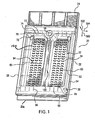
- FIG. 1 shows blade outer air seal (BOAS) 20.
- the BOAS has a main body portion 22 having a leading/upstream/forward end 24 and a trailing/downstream/aft end 26.
- FIG. 1 further shows an approximate longitudinal/overall-downstream/aftward direction 500, an approximate radial outward direction 502, and an approximate circumferential direction 504.
- the body has first and second circumferential ends or matefaces 28 and 30.
- the body has an ID face 32 and an OD face 34.
- the exemplary BOAS has a plurality of mounting hooks.
- the exemplary BOAS has a single forward mounting hook 42 having a forwardly-projecting distal portion recessed aft of the forward end 24.
- the exemplary BOAS has a single aft hook 44 having a rearwardly-projecting distal portion slightly recessed from the aft end 26.
- the exemplary hook distal portions are formed as full width lips extending from a wall 46 circumscribing a chamber 48.
- a floor or base 50 of the chamber is locally formed by a central portion of the OD face 34.
- a circumferential ring array of a plurality of the BOAS 22 may encircle an associated blade stage of a gas turbine engine.
- the assembled ID faces 32 thus locally bound an outboard extreme of the core flowpath 52 (FIG. 4).
- the BOAS 22 may have features for interlocking the array.
- the exemplary matefaces 28 and 30 include slots 54 for accommodating edges of seals (not shown) spanning junctions between adjacent BOAS 22.
- FIG. 1 further shows a socket 56 for receiving a locator pin (not shown) locating the BOAS 22 relative to the environmental structure 40.
- the BOAS may be air-cooled.
- bleed air may be directed to a chamber 58 (FIG. 4) immediately outboard of the plate 40.
- the bleed air may be directed through impingement holes 60 in the plate 40 to the chamber 48.
- Air may exit the chamber 48 through discharge passageways.
- the exemplary BOAS of FIG. 1 shows exemplary leading passageways 70 extending from inlets 72 in a leading wall surface portion 74 of the wall 46.
- the exemplary passageways 70 are arranged in two groups of three on either side of a longitudinal/radial median plane 510 (FIG. 2).
- the exemplary passageways 70 have outlets 76 along the wall 46 at the base of a channel 78 formed by the hook 42.
- trailing passageways 80 have inlets 82 in a trailing wall surface portions 84 and outlets 86 at a channel 88.
- Groups of first and second lateral passageways 90 and 92 extend respectively from inlets 94 along the surface 50 to outlets 96 on the adjacent matefaces.
- the central longitudinal dividing wall 100 extends upward from the floor 50 to divide the chamber 48 into first and second wells.
- the exemplary wall 100 is a partial height wall extending subflush to a rim of the wall 46 to structurally stiffen the BOAS.
- FIG. 4 shows the airflows 120 passing through the holes 60.
- the presence of both leading passageways 70 and trailing passageways 80 causes a split in the flow with a first portion 122 flowing generally forward and a second portion 124 flowing generally rearward.
- a transverse plane 520 generally marks the split between these net flows.
- Each chevron 150 includes first and second legs 152 and 154. Each leg 152 and 154 is elongate having a length L 1 , a width W 1 , and a height e (FIG. 6). Along the lengthwise dimension, each leg has a leading side or face 160 and a trailing side or face 162. Along the widthwise dimension, each leg has a leading end 164 and a trailing end 166. The leading ends 164 of each leg pair are separated by a gap 168 adjacent the omitted chevron apex. Omission of the chevron apex may result from castability considerations.
- FIG. 3 shows the plane 520 as dividing the chevrons 150 into two subgroups.
- the legs i.e., the side/faces 160 and 162 of each chevron 150
- diverge away from the plane 520 i.e., in a downstream direction of the associated flow 122 or 124.
- the plane 520 may be positioned where the flows split.
- the wall 100 also divides the chevrons into two subgroups on either side of the wall 100.
- the wall 100 serves as a structural support to add rigidity to the BOAS. It also serves to divide the flow-path within the BOAS into two sections.
- the subgroups form four discrete subgroups/arrays.
- each array is three chevrons wide, the two leading arrays are ten chevrons long, and the two trailing arrays are eleven chevrons long.
- the exemplary arrays are right arrays of constant longitudinal and transverse spacing.
- the flow of air over the chevrons is directed such that the sub-layer of the boundary layer is tripped into the turbulent regime.
- the directional bias of the chevrons allows this tripped region to grow along the direction of the chevron trip strips thereby causing additional coolant (air) to be in contact with the surface such increases the heat transfer.
- the spacing of the chevrons is set so that the coolant flow will be tripped over one chevron and have adequate spacing to re-attach to the floor 50 before the next chevron is reached. This separation and re-attachment is believed to allow the chevrons to provide superior heat transfer relative to closely spaced pin protuberances as in the prior art.
- the prior art may merely serve to increase the wetted surface area rather than fundamentally changing the mode of heat transfer obtained on the BOAS surface.
- the BOAS is cooled by three methods: impingement cooling from holes 60, convective heat transfer cooling from the chevron trip strips 154, and film-cooling from holes 70, 80, 90, and 92.
- the convective heat transfer from the chevron trip strips is believed to be the dominant mode of cooling. For several reasons this is believed more effective than the prior art arrays of small pin-fins providing the backside cooling.
- the apex of the chevron is oriented in the direction of the flow on the right and left part of the BOAS surface (with flow toward cooling holes 70 and 80). This increases turbulence of the flow.
- the chevron generates double vortices, which further increases the heat transfer coefficients along the cooled surface uniformly.
- the height of the chevron is selected to be higher than the sub-layer of the boundary layer to ensure flow separation and re-attachment between two neighboring chevrons. This reattachment enhances the heat transfer coefficient. In an exemplary reengineering from a pin-fin enhancement configuration, these three factors are believed provide the BOAS with relatively uniform cooling with much higher heat transfer coefficients (e.g., an increase of more than 50%, more particularly in the vicinity of 80-110%).
- the particular value for the height was chosen in conjunction with the directional spacing of the chevrons (pitch) to optimize the effectiveness of the chevrons and helps to give a uniform wall temperature.
- the final method of cooling for the part is the film-cooling, which cools the extreme ends of the BOAS. With this method of cooling, it is the BOAS is relatively uniformly cooled with low temperature gradient, which leads to low stress and strain and much improved service life.
- Nominal parameters defining the chevron shape are referred to as P/e and e/H, where P is the linear spacing between two consecutive chevrons in the 500 direction, e is the height of the chevron and H is the distance between the impingement holes 60 (plate underside) and the floor 50.
- Exemplary dimensions are: 3 ⁇ P/e ⁇ 50, more narrowly 5 ⁇ P/e ⁇ 10 or 5 ⁇ P/e ⁇ 15; and 0.03 ⁇ e/h ⁇ 0.3, more narrowly 0.05 ⁇ e/h ⁇ 0.10.
- the height e may also reflect castability considerations.
- Exemplary e are 0.030+/-0.002 inch (0.762 mm +/- 0.051 mm), more broadly 0.02-0.04 inch (0.51 - 1.02 mm). In a reengineering situation, e will typically be greater (e.g., 10-50% greater) than a pin-fin height of the baseline part.
Landscapes
- Engineering & Computer Science (AREA)
- Mechanical Engineering (AREA)
- General Engineering & Computer Science (AREA)
- Turbine Rotor Nozzle Sealing (AREA)
Abstract
Description
- The invention relates to gas turbine engines. More particularly, the invention relates to casting of cooled shrouds or blade outer air seals (BOAS).
- BOAS segments may be internally cooled by bleed air. For example, cooling air may be fed into a plenum at the outboard (OD) side of the BOAS. The cooling air may pass through passageways in the seal body and exit outlet ports in the ID side of the body (e.g. to film cool the ID face). Air may also exit along the circumferential ends (matefaces) of the BOAS so as to be vented into the adjacent inter-segment region (e.g., to help cool feather seal segments sealing the adjacent BOAS segments).
- The BOAS segments may be cast via an investment casting process. In an exemplary casting process, wax may be molded in a die to form a pattern. The pattern may be shelled (e.g., a stuccoing process to form a ceramic shell). The wax may be removed from the shell. Metal may be cast in the shell. The shell may be destructively removed. After shell removal, the passageways may be drilled. Alternatively, some or all of the passageways may be cast using a casting core.
- One aspect of the invention involves a blade outer air seal (BOAS). The BOAS has a body having an inner (ID) face and an outer (OD) face, first and second circumferential ends, and fore and aft longitudinal ends. The BOAS has one or more mounting hooks extending from the body. The OD face comprises a plurality of transversely elongate protuberances. The protuberances include rearwardly divergent first protuberances and forwardly divergent second protuberances.
- The details of one or more embodiments of the invention are set forth in the accompanying drawings and the description below. Other features and advantages of the invention will be apparent from the description and drawings, and from the claims.
-
- FIG. 1 is a view of a blade outer airseal (BOAS).
- FIG. 2 is an OD/top view of the BOAS of FIG. 1.
- FIG. 3 is an enlarged view of a surface enhancement of the BOAS of FIG. 2.
- FIG. 4 is a first circumferential end view of the BOAS of FIG. 1.
- FIG. 5 is a longitudinal sectional of the BOAS of FIG. 1.
- FIG. 6 is an enlarged view of the BOAS of FIG. 5.
- FIG. 7 is an OD/top view of a prior art BOAS.
- Like reference numbers and designations in the various drawings indicate like elements.
- FIG. 1 shows blade outer air seal (BOAS) 20. The BOAS has a
main body portion 22 having a leading/upstream/forward end 24 and a trailing/downstream/aft end 26. FIG. 1 further shows an approximate longitudinal/overall-downstream/aftward direction 500, an approximate radialoutward direction 502, and an approximatecircumferential direction 504. The body has first and second circumferential ends ormatefaces ID face 32 and anOD face 34. - To mount the BOAS to environmental structure 40 (FIG. 4), the exemplary BOAS has a plurality of mounting hooks. The exemplary BOAS has a single
forward mounting hook 42 having a forwardly-projecting distal portion recessed aft of theforward end 24. The exemplary BOAS has asingle aft hook 44 having a rearwardly-projecting distal portion slightly recessed from theaft end 26. The exemplary hook distal portions are formed as full width lips extending from awall 46 circumscribing achamber 48. A floor orbase 50 of the chamber is locally formed by a central portion of theOD face 34. - A circumferential ring array of a plurality of the
BOAS 22 may encircle an associated blade stage of a gas turbine engine. The assembled ID faces 32 thus locally bound an outboard extreme of the core flowpath 52 (FIG. 4). The BOAS 22 may have features for interlocking the array. Theexemplary matefaces slots 54 for accommodating edges of seals (not shown) spanning junctions betweenadjacent BOAS 22. FIG. 1 further shows asocket 56 for receiving a locator pin (not shown) locating theBOAS 22 relative to theenvironmental structure 40. - The BOAS may be air-cooled. For example, bleed air may be directed to a chamber 58 (FIG. 4) immediately outboard of the
plate 40. The bleed air may be directed throughimpingement holes 60 in theplate 40 to thechamber 48. Air may exit thechamber 48 through discharge passageways. The exemplary BOAS of FIG. 1 shows exemplary leadingpassageways 70 extending frominlets 72 in a leadingwall surface portion 74 of thewall 46. Theexemplary passageways 70 are arranged in two groups of three on either side of a longitudinal/radial median plane 510 (FIG. 2). Theexemplary passageways 70 haveoutlets 76 along thewall 46 at the base of achannel 78 formed by thehook 42. Similarly, trailingpassageways 80 haveinlets 82 in a trailingwall surface portions 84 andoutlets 86 at achannel 88. Groups of first and secondlateral passageways inlets 94 along thesurface 50 tooutlets 96 on the adjacent matefaces. The central longitudinal dividingwall 100 extends upward from thefloor 50 to divide thechamber 48 into first and second wells. Theexemplary wall 100 is a partial height wall extending subflush to a rim of thewall 46 to structurally stiffen the BOAS. - FIG. 4 shows the
airflows 120 passing through theholes 60. The presence of both leadingpassageways 70 and trailingpassageways 80 causes a split in the flow with afirst portion 122 flowing generally forward and asecond portion 124 flowing generally rearward. Atransverse plane 520 generally marks the split between these net flows. - Surface enhancements are provided along the
floor 50 to maximize heat transfer from theflows chevron 150 includes first andsecond legs leg face 160 and a trailing side orface 162. Along the widthwise dimension, each leg has aleading end 164 and a trailingend 166. The leading ends 164 of each leg pair are separated by agap 168 adjacent the omitted chevron apex. Omission of the chevron apex may result from castability considerations. - FIG. 3 shows the
plane 520 as dividing thechevrons 150 into two subgroups. The legs (i.e., the side/faces 160 and 162 of each chevron 150) diverge away from the plane 520 (i.e., in a downstream direction of the associatedflow 122 or 124). In a reengineering situation, theplane 520 may be positioned where the flows split. Thewall 100 also divides the chevrons into two subgroups on either side of thewall 100. Thewall 100 serves as a structural support to add rigidity to the BOAS. It also serves to divide the flow-path within the BOAS into two sections. Thus, the subgroups form four discrete subgroups/arrays. In the exemplary BOAS, each array is three chevrons wide, the two leading arrays are ten chevrons long, and the two trailing arrays are eleven chevrons long. The exemplary arrays are right arrays of constant longitudinal and transverse spacing. - The flow of air over the chevrons is directed such that the sub-layer of the boundary layer is tripped into the turbulent regime. The directional bias of the chevrons allows this tripped region to grow along the direction of the chevron trip strips thereby causing additional coolant (air) to be in contact with the surface such increases the heat transfer.
- The spacing of the chevrons is set so that the coolant flow will be tripped over one chevron and have adequate spacing to re-attach to the
floor 50 before the next chevron is reached. This separation and re-attachment is believed to allow the chevrons to provide superior heat transfer relative to closely spaced pin protuberances as in the prior art. The prior art may merely serve to increase the wetted surface area rather than fundamentally changing the mode of heat transfer obtained on the BOAS surface. - The BOAS is cooled by three methods: impingement cooling from
holes 60, convective heat transfer cooling from the chevron trip strips 154, and film-cooling fromholes - The particular value for the height was chosen in conjunction with the directional spacing of the chevrons (pitch) to optimize the effectiveness of the chevrons and helps to give a uniform wall temperature. The final method of cooling for the part is the film-cooling, which cools the extreme ends of the BOAS. With this method of cooling, it is the BOAS is relatively uniformly cooled with low temperature gradient, which leads to low stress and strain and much improved service life.
- Nominal parameters defining the chevron shape are referred to as P/e and e/H, where P is the linear spacing between two consecutive chevrons in the 500 direction, e is the height of the chevron and H is the distance between the impingement holes 60 (plate underside) and the
floor 50. - Exemplary dimensions are: 3≤P/e≤50, more narrowly 5≤P/e≤10 or 5≤P/e≤15; and 0.03≤e/h≤0.3, more narrowly 0.05≤e/h≤0.10. The height e may also reflect castability considerations. Exemplary e are 0.030+/-0.002 inch (0.762 mm +/- 0.051 mm), more broadly 0.02-0.04 inch (0.51 - 1.02 mm). In a reengineering situation, e will typically be greater (e.g., 10-50% greater) than a pin-fin height of the baseline part.
- [0001] One or more embodiments of the present invention have been described. Nevertheless, it will be understood that various modifications may be made without departing from the scope of the invention. For example, when implemented in the reengineering of a baseline BOAS, or using existing manufacturing techniques and equipment, details of the baseline BOAS or existing techniques or equipment may influence details of any particular implementation. Accordingly, other embodiments are within the scope of the following claims.
Claims (18)
- A blade outer air seal (20) comprising:a body (22) having an ID, face (32) and an OD face (34), first and second circumferential ends (28, 30), fore and aft longitudinal ends (24, 26) and a plurality of cooling passageways; andone or more mounting hooks (42, 44),wherein:the OD face (34) comprises a plurality of transversely elongate protuberances (150) including, rearwardly divergent first protuberances (150) and forwardly divergent second protuberances (150).
- The seal of claim 1 wherein:
the protuberances (150) have heights of 0.030+/-0.002 inch (0.762 +/- 0.051 mm). - The seal of claim 1 or 2 wherein the cooling passageways include:a leading plurality (70) having inlets (72) along a leading wall surface portion (74) forward of the protuberances (150);a trailing plurality (80) having inlets (82) along a trailing wall surface portion (84) aft of the protuberances (150); andfirst and second lateral pluralities (70, 72) having inlets (94) among the protuberances (150).
- The seal of any preceding claim wherein:the protuberances (180) are positioned in right arrays; andinlets of at least some the cooling passageways along the OD face (34) are positioned among the protuberances (150).
- The seal of any preceding claim wherein:the seal (20) is formed of a nickel-based superalloy.
- The seal of claim 5 wherein:the seal (20) has a coating.
- The seal of any preceding claim wherein:the first protuberances (150) have rearwardly divergent fore and aft faces; andthe second protuberances (150) have forwardly divergent fore and aft faces.
- The seal of any preceding claim wherein:the body (22) has a perimeter wall (46) and the protuberances (150) are along a base (50) of a compartment (48) laterally surrounded by the perimeter wall (46).
- The seal of any preceding claim wherein:the protuberances (150) are positioned in four discrete right arrays.
- A combination comprising:a circumferential array of seals (20) of any preceding claim; andblade stage with blade tips in facing proximity to the seal ID faces.
- The combination of claim 10 wherein:seal mounting hooks (42, 44) engage mating features of a support structure
- A blade outer air seal (20) comprising:a body (22) having an ID face (32) and an OD face (34), first and second circumferential ends (28, 30), and fore and aft ends (24, 26); anda pair of mounting hooks (42, 44),wherein:the OD face (34) comprises a plurality of chevron or apex-less chevron planform protuberances (150).
- The seal of claim 12 wherein:the protuberances (150) include a fore group of forwardly divergent protuberances and an aft group of reawardly divergent protuberances.
- The seal of claim 13 wherein:a longitudinal dividing wall (100) separates the protuberances (150) into first and second circumferential groups.
- The seal of claim 14 further comprising:outlet passageways extending from inlets among the protuberances (150) to outlets along the first and second circumferential ends (28, 30).
- A combination comprising:a seal of any of claims 12 to 15;an impingement plate (40) having an array of apertures (60); andan airflow through the apertures (60) and then through the passageways.
- The combination of claim 16 wherein:the airflow forms a forwardly-directed portion (122) flowing over the second protuberances (150) and a rearwardly-directed portion (124) flowing over the first protuberances (150).
- The combination of claim 16 or 17 wherein:a ratio of protrusion height (e) to a distance between an underside of the plate (40) and a floor (50) of the OD face (34) is between 0.05 and 0.10, inclusive.
Applications Claiming Priority (1)
| Application Number | Priority Date | Filing Date | Title |
|---|---|---|---|
| US11/580,171 US7553128B2 (en) | 2006-10-12 | 2006-10-12 | Blade outer air seals |
Publications (2)
| Publication Number | Publication Date |
|---|---|
| EP1914390A2 true EP1914390A2 (en) | 2008-04-23 |
| EP1914390A3 EP1914390A3 (en) | 2011-05-18 |
Family
ID=38904855
Family Applications (1)
| Application Number | Title | Priority Date | Filing Date |
|---|---|---|---|
| EP07254066A Withdrawn EP1914390A3 (en) | 2006-10-12 | 2007-10-12 | Blade outer air seals |
Country Status (2)
| Country | Link |
|---|---|
| US (1) | US7553128B2 (en) |
| EP (1) | EP1914390A3 (en) |
Cited By (9)
| Publication number | Priority date | Publication date | Assignee | Title |
|---|---|---|---|---|
| WO2013076109A1 (en) * | 2011-11-21 | 2013-05-30 | Siemens Aktiengesellschaft | Coolable hot-gas component for a gas turbine |
| EP2628905A3 (en) * | 2012-02-17 | 2014-06-04 | United Technologies Corporation | Turbomachine hot-section component protrusion, corresponding component and method of augmentIng a surface area |
| WO2015031764A1 (en) * | 2013-08-29 | 2015-03-05 | United Technologies Corporation | Blade outer air seal made of ceramic matrix composite |
| US9310852B2 (en) | 2013-10-03 | 2016-04-12 | Lenovo Enterprise Solutions (Singapore) Pte. Ltd. | Automatic sealing of a gap along a chassis positioned in a rack |
| EP3040516A1 (en) * | 2014-12-31 | 2016-07-06 | General Electric Company | Engine component with vortex generator |
| EP3192969A1 (en) * | 2016-01-15 | 2017-07-19 | United Technologies Corporation | Blade outer air seal (boa) for a gas turbine engine with optimized leading edge geometry |
| EP3584408A1 (en) * | 2018-06-18 | 2019-12-25 | United Technologies Corporation | Trip strip configuration for gaspath component in a gas turbine engine |
| WO2020239560A1 (en) * | 2019-05-29 | 2020-12-03 | Siemens Aktiengesellschaft | Heatshield for a gas turbine engine |
| EP3696377B1 (en) * | 2013-10-31 | 2025-08-27 | Siemens Aktiengesellschaft | Gas turbine engine component comprising a trailing edge cooling using angled impingement on surface enhanced with cast chevron arrangements |
Families Citing this family (36)
| Publication number | Priority date | Publication date | Assignee | Title |
|---|---|---|---|---|
| US9133715B2 (en) * | 2006-09-20 | 2015-09-15 | United Technologies Corporation | Structural members in a pedestal array |
| US8439639B2 (en) * | 2008-02-24 | 2013-05-14 | United Technologies Corporation | Filter system for blade outer air seal |
| US8534995B2 (en) * | 2009-03-05 | 2013-09-17 | United Technologies Corporation | Turbine engine sealing arrangement |
| US8740551B2 (en) * | 2009-08-18 | 2014-06-03 | Pratt & Whitney Canada Corp. | Blade outer air seal cooling |
| US9085053B2 (en) | 2009-12-22 | 2015-07-21 | United Technologies Corporation | In-situ turbine blade tip repair |
| US8556575B2 (en) * | 2010-03-26 | 2013-10-15 | United Technologies Corporation | Blade outer seal for a gas turbine engine |
| US8613590B2 (en) | 2010-07-27 | 2013-12-24 | United Technologies Corporation | Blade outer air seal and repair method |
| US8876458B2 (en) | 2011-01-25 | 2014-11-04 | United Technologies Corporation | Blade outer air seal assembly and support |
| US8840371B2 (en) | 2011-10-07 | 2014-09-23 | General Electric Company | Methods and systems for use in regulating a temperature of components |
| US8998572B2 (en) | 2012-06-04 | 2015-04-07 | United Technologies Corporation | Blade outer air seal for a gas turbine engine |
| US9574455B2 (en) | 2012-07-16 | 2017-02-21 | United Technologies Corporation | Blade outer air seal with cooling features |
| US9506367B2 (en) | 2012-07-20 | 2016-11-29 | United Technologies Corporation | Blade outer air seal having inward pointing extension |
| US9617866B2 (en) | 2012-07-27 | 2017-04-11 | United Technologies Corporation | Blade outer air seal for a gas turbine engine |
| US9115596B2 (en) | 2012-08-07 | 2015-08-25 | United Technologies Corporation | Blade outer air seal having anti-rotation feature |
| US20140064969A1 (en) * | 2012-08-29 | 2014-03-06 | Dmitriy A. Romanov | Blade outer air seal |
| US9322560B2 (en) * | 2012-09-28 | 2016-04-26 | United Technologies Corporation | Combustor bulkhead assembly |
| US9803491B2 (en) | 2012-12-31 | 2017-10-31 | United Technologies Corporation | Blade outer air seal having shiplap structure |
| US10006367B2 (en) * | 2013-03-15 | 2018-06-26 | United Technologies Corporation | Self-opening cooling passages for a gas turbine engine |
| US10053999B2 (en) | 2013-04-18 | 2018-08-21 | United Technologies Corporation | Radial position control of case supported structure with axial reaction member |
| WO2014189873A2 (en) | 2013-05-21 | 2014-11-27 | Siemens Energy, Inc. | Gas turbine ring segment cooling apparatus |
| US9797262B2 (en) | 2013-07-26 | 2017-10-24 | United Technologies Corporation | Split damped outer shroud for gas turbine engine stator arrays |
| US10309255B2 (en) | 2013-12-19 | 2019-06-04 | United Technologies Corporation | Blade outer air seal cooling passage |
| US10316683B2 (en) | 2014-04-16 | 2019-06-11 | United Technologies Corporation | Gas turbine engine blade outer air seal thermal control system |
| EP3183431B1 (en) * | 2014-08-22 | 2018-10-10 | Siemens Aktiengesellschaft | Shroud cooling system for shrouds adjacent to airfoils within gas turbine engines |
| US10309252B2 (en) | 2015-12-16 | 2019-06-04 | General Electric Company | System and method for cooling turbine shroud trailing edge |
| US10221719B2 (en) | 2015-12-16 | 2019-03-05 | General Electric Company | System and method for cooling turbine shroud |
| US10378380B2 (en) | 2015-12-16 | 2019-08-13 | General Electric Company | Segmented micro-channel for improved flow |
| US10815812B2 (en) * | 2017-05-12 | 2020-10-27 | Raytheon Technologies Corporation | Geometry optimized blade outer air seal for thermal loads |
| US10502093B2 (en) * | 2017-12-13 | 2019-12-10 | Pratt & Whitney Canada Corp. | Turbine shroud cooling |
| US11268402B2 (en) | 2018-04-11 | 2022-03-08 | Raytheon Technologies Corporation | Blade outer air seal cooling fin |
| US10989070B2 (en) * | 2018-05-31 | 2021-04-27 | General Electric Company | Shroud for gas turbine engine |
| US10822962B2 (en) * | 2018-09-27 | 2020-11-03 | Raytheon Technologies Corporation | Vane platform leading edge recessed pocket with cover |
| US10822987B1 (en) | 2019-04-16 | 2020-11-03 | Pratt & Whitney Canada Corp. | Turbine stator outer shroud cooling fins |
| US11041403B2 (en) | 2019-04-16 | 2021-06-22 | Pratt & Whitney Canada Corp. | Gas turbine engine, part thereof, and associated method of operation |
| US11454137B1 (en) * | 2021-05-14 | 2022-09-27 | Doosan Heavy Industries & Construction Co., Ltd | Gas turbine inner shroud with array of protuberances |
| US12286898B2 (en) * | 2023-04-18 | 2025-04-29 | Rtx Corporation | Layout for asymmetric cast trips in long passages |
Citations (1)
| Publication number | Priority date | Publication date | Assignee | Title |
|---|---|---|---|---|
| EP1676981A2 (en) | 2004-12-29 | 2006-07-05 | United Technologies Corporation | Coolable turbine shroud seal segment |
Family Cites Families (9)
| Publication number | Priority date | Publication date | Assignee | Title |
|---|---|---|---|---|
| US5609469A (en) * | 1995-11-22 | 1997-03-11 | United Technologies Corporation | Rotor assembly shroud |
| US5797726A (en) * | 1997-01-03 | 1998-08-25 | General Electric Company | Turbulator configuration for cooling passages or rotor blade in a gas turbine engine |
| US6393331B1 (en) * | 1998-12-16 | 2002-05-21 | United Technologies Corporation | Method of designing a turbine blade outer air seal |
| DE69940948D1 (en) * | 1999-01-25 | 2009-07-16 | Gen Electric | Internal cooling circuit for a gas turbine blade |
| US6379528B1 (en) * | 2000-12-12 | 2002-04-30 | General Electric Company | Electrochemical machining process for forming surface roughness elements on a gas turbine shroud |
| US7033138B2 (en) * | 2002-09-06 | 2006-04-25 | Mitsubishi Heavy Industries, Ltd. | Ring segment of gas turbine |
| US6924002B2 (en) * | 2003-02-24 | 2005-08-02 | General Electric Company | Coating and coating process incorporating raised surface features for an air-cooled surface |
| US7373778B2 (en) * | 2004-08-26 | 2008-05-20 | General Electric Company | Combustor cooling with angled segmented surfaces |
| US7575414B2 (en) * | 2005-04-01 | 2009-08-18 | General Electric Company | Turbine nozzle with trailing edge convection and film cooling |
-
2006
- 2006-10-12 US US11/580,171 patent/US7553128B2/en not_active Expired - Fee Related
-
2007
- 2007-10-12 EP EP07254066A patent/EP1914390A3/en not_active Withdrawn
Patent Citations (1)
| Publication number | Priority date | Publication date | Assignee | Title |
|---|---|---|---|---|
| EP1676981A2 (en) | 2004-12-29 | 2006-07-05 | United Technologies Corporation | Coolable turbine shroud seal segment |
Cited By (16)
| Publication number | Priority date | Publication date | Assignee | Title |
|---|---|---|---|---|
| WO2013076109A1 (en) * | 2011-11-21 | 2013-05-30 | Siemens Aktiengesellschaft | Coolable hot-gas component for a gas turbine |
| EP2602439A1 (en) * | 2011-11-21 | 2013-06-12 | Siemens Aktiengesellschaft | Coolable hot gas component for a gas turbine |
| EP2628905A3 (en) * | 2012-02-17 | 2014-06-04 | United Technologies Corporation | Turbomachine hot-section component protrusion, corresponding component and method of augmentIng a surface area |
| US9255491B2 (en) | 2012-02-17 | 2016-02-09 | United Technologies Corporation | Surface area augmentation of hot-section turbomachine component |
| WO2015031764A1 (en) * | 2013-08-29 | 2015-03-05 | United Technologies Corporation | Blade outer air seal made of ceramic matrix composite |
| US9310852B2 (en) | 2013-10-03 | 2016-04-12 | Lenovo Enterprise Solutions (Singapore) Pte. Ltd. | Automatic sealing of a gap along a chassis positioned in a rack |
| EP3696377B1 (en) * | 2013-10-31 | 2025-08-27 | Siemens Aktiengesellschaft | Gas turbine engine component comprising a trailing edge cooling using angled impingement on surface enhanced with cast chevron arrangements |
| US9777635B2 (en) | 2014-12-31 | 2017-10-03 | General Electric Company | Engine component |
| EP3040516A1 (en) * | 2014-12-31 | 2016-07-06 | General Electric Company | Engine component with vortex generator |
| EP3192969A1 (en) * | 2016-01-15 | 2017-07-19 | United Technologies Corporation | Blade outer air seal (boa) for a gas turbine engine with optimized leading edge geometry |
| US10138748B2 (en) | 2016-01-15 | 2018-11-27 | United Technologies Corporation | Gas turbine engine components with optimized leading edge geometry |
| EP4459109A3 (en) * | 2016-01-15 | 2025-04-23 | RTX Corporation | Gas turbine engine component with optimized leading edge geometry |
| EP3584408A1 (en) * | 2018-06-18 | 2019-12-25 | United Technologies Corporation | Trip strip configuration for gaspath component in a gas turbine engine |
| US10808552B2 (en) | 2018-06-18 | 2020-10-20 | Raytheon Technologies Corporation | Trip strip configuration for gaspath component in a gas turbine engine |
| WO2020239560A1 (en) * | 2019-05-29 | 2020-12-03 | Siemens Aktiengesellschaft | Heatshield for a gas turbine engine |
| US12025019B2 (en) | 2019-05-29 | 2024-07-02 | Siemens Energy Global GmbH & Co. KG | Heatshield for a gas turbine engine |
Also Published As
| Publication number | Publication date |
|---|---|
| US7553128B2 (en) | 2009-06-30 |
| US20080089787A1 (en) | 2008-04-17 |
| EP1914390A3 (en) | 2011-05-18 |
Similar Documents
| Publication | Publication Date | Title |
|---|---|---|
| US7553128B2 (en) | Blade outer air seals | |
| EP1965033B1 (en) | Blade outer air seal | |
| US6955522B2 (en) | Method and apparatus for cooling an airfoil | |
| EP2019187B1 (en) | Apparatus and methods for providing vane platform cooling | |
| US8123466B2 (en) | Blade outer air seal | |
| US8562295B1 (en) | Three piece bonded thin wall cooled blade | |
| US8608430B1 (en) | Turbine vane with near wall multiple impingement cooling | |
| US8043060B1 (en) | Turbine blade with trailing edge cooling | |
| US7217092B2 (en) | Method and apparatus for reducing turbine blade temperatures | |
| EP2586982A2 (en) | Method and apparatus for cooling gas turbine rotor blades | |
| US20070104576A1 (en) | Peripheral microcircuit serpentine cooling for turbine airfoils | |
| CA2848867C (en) | Method and apparatus for cooling gas turbine rotor blades | |
| US8257041B1 (en) | Turbine blade with triple spiral serpentine flow cooling circuits | |
| US8613597B1 (en) | Turbine blade with trailing edge cooling | |
| US8628294B1 (en) | Turbine stator vane with purge air channel | |
| JP2002004805A (en) | End rail cooling method for combined high and low pressure turbine shroud. | |
| US8016564B1 (en) | Turbine blade with leading edge impingement cooling | |
| JP2015521706A (en) | Turbine airfoil with cast platform cooling circuit | |
| CA2540906A1 (en) | Turbine nozzle with trailing edge convection and film cooling | |
| US20190178103A1 (en) | Turbine shroud cooling | |
| US7458778B1 (en) | Turbine airfoil with a bifurcated counter flow serpentine path | |
| US7458779B2 (en) | Gas turbine or compressor blade | |
| JP3642537B2 (en) | Gas turbine cooling blade | |
| EP2067929A2 (en) | Air-cooled gas turbine engine vane |
Legal Events
| Date | Code | Title | Description |
|---|---|---|---|
| PUAI | Public reference made under article 153(3) epc to a published international application that has entered the european phase |
Free format text: ORIGINAL CODE: 0009012 |
|
| AK | Designated contracting states |
Kind code of ref document: A2 Designated state(s): AT BE BG CH CY CZ DE DK EE ES FI FR GB GR HU IE IS IT LI LT LU LV MC MT NL PL PT RO SE SI SK TR |
|
| AX | Request for extension of the european patent |
Extension state: AL BA HR MK RS |
|
| PUAL | Search report despatched |
Free format text: ORIGINAL CODE: 0009013 |
|
| AK | Designated contracting states |
Kind code of ref document: A3 Designated state(s): AT BE BG CH CY CZ DE DK EE ES FI FR GB GR HU IE IS IT LI LT LU LV MC MT NL PL PT RO SE SI SK TR |
|
| AX | Request for extension of the european patent |
Extension state: AL BA HR MK RS |
|
| 17P | Request for examination filed |
Effective date: 20111116 |
|
| AKX | Designation fees paid |
Designated state(s): DE GB |
|
| STAA | Information on the status of an ep patent application or granted ep patent |
Free format text: STATUS: THE APPLICATION HAS BEEN WITHDRAWN |
|
| 18W | Application withdrawn |
Effective date: 20140606 |