EP1914383A2 - Fanschaufel aus Textilverbundwerkstoff - Google Patents
Fanschaufel aus Textilverbundwerkstoff Download PDFInfo
- Publication number
- EP1914383A2 EP1914383A2 EP07117952A EP07117952A EP1914383A2 EP 1914383 A2 EP1914383 A2 EP 1914383A2 EP 07117952 A EP07117952 A EP 07117952A EP 07117952 A EP07117952 A EP 07117952A EP 1914383 A2 EP1914383 A2 EP 1914383A2
- Authority
- EP
- European Patent Office
- Prior art keywords
- blade
- carbon fiber
- blade root
- fiber layers
- fan blade
- Prior art date
- Legal status (The legal status is an assumption and is not a legal conclusion. Google has not performed a legal analysis and makes no representation as to the accuracy of the status listed.)
- Granted
Links
- 239000002131 composite material Substances 0.000 title claims description 12
- 239000004753 textile Substances 0.000 title claims description 7
- 239000000463 material Substances 0.000 title description 3
- 229920000049 Carbon (fiber) Polymers 0.000 claims abstract description 45
- 239000004917 carbon fiber Substances 0.000 claims abstract description 45
- VNWKTOKETHGBQD-UHFFFAOYSA-N methane Chemical compound C VNWKTOKETHGBQD-UHFFFAOYSA-N 0.000 claims abstract description 44
- 239000003365 glass fiber Substances 0.000 claims abstract description 14
- 239000000835 fiber Substances 0.000 claims description 32
- 230000007704 transition Effects 0.000 claims description 32
- 239000004033 plastic Substances 0.000 claims description 19
- 229920003023 plastic Polymers 0.000 claims description 19
- 230000008595 infiltration Effects 0.000 claims description 7
- 238000001764 infiltration Methods 0.000 claims description 7
- 230000006835 compression Effects 0.000 claims description 2
- 238000007906 compression Methods 0.000 claims description 2
- 230000003247 decreasing effect Effects 0.000 claims description 2
- 239000010410 layer Substances 0.000 description 58
- 239000011229 interlayer Substances 0.000 description 8
- OKTJSMMVPCPJKN-UHFFFAOYSA-N Carbon Chemical compound [C] OKTJSMMVPCPJKN-UHFFFAOYSA-N 0.000 description 5
- 238000005452 bending Methods 0.000 description 5
- 230000005540 biological transmission Effects 0.000 description 5
- 229910052799 carbon Inorganic materials 0.000 description 5
- 230000032798 delamination Effects 0.000 description 4
- 238000004519 manufacturing process Methods 0.000 description 3
- 239000000057 synthetic resin Substances 0.000 description 3
- 229920003002 synthetic resin Polymers 0.000 description 3
- RTAQQCXQSZGOHL-UHFFFAOYSA-N Titanium Chemical compound [Ti] RTAQQCXQSZGOHL-UHFFFAOYSA-N 0.000 description 2
- 239000011152 fibreglass Substances 0.000 description 2
- 230000003014 reinforcing effect Effects 0.000 description 2
- 239000011347 resin Substances 0.000 description 2
- 229920005989 resin Polymers 0.000 description 2
- 239000010936 titanium Substances 0.000 description 2
- 229910052719 titanium Inorganic materials 0.000 description 2
- 230000015572 biosynthetic process Effects 0.000 description 1
- 239000004918 carbon fiber reinforced polymer Substances 0.000 description 1
- 238000005253 cladding Methods 0.000 description 1
- 230000007423 decrease Effects 0.000 description 1
- 238000000280 densification Methods 0.000 description 1
- 230000001419 dependent effect Effects 0.000 description 1
- 238000011161 development Methods 0.000 description 1
- 230000018109 developmental process Effects 0.000 description 1
- 239000004744 fabric Substances 0.000 description 1
- 239000002657 fibrous material Substances 0.000 description 1
- 229910052751 metal Inorganic materials 0.000 description 1
- 239000002184 metal Substances 0.000 description 1
- 238000012856 packing Methods 0.000 description 1
- 230000002028 premature Effects 0.000 description 1
Images

Classifications
-
- F—MECHANICAL ENGINEERING; LIGHTING; HEATING; WEAPONS; BLASTING
- F01—MACHINES OR ENGINES IN GENERAL; ENGINE PLANTS IN GENERAL; STEAM ENGINES
- F01D—NON-POSITIVE DISPLACEMENT MACHINES OR ENGINES, e.g. STEAM TURBINES
- F01D5/00—Blades; Blade-carrying members; Heating, heat-insulating, cooling or antivibration means on the blades or the members
- F01D5/12—Blades
- F01D5/28—Selecting particular materials; Particular measures relating thereto; Measures against erosion or corrosion
- F01D5/282—Selecting composite materials, e.g. blades with reinforcing filaments
-
- B—PERFORMING OPERATIONS; TRANSPORTING
- B29—WORKING OF PLASTICS; WORKING OF SUBSTANCES IN A PLASTIC STATE IN GENERAL
- B29C—SHAPING OR JOINING OF PLASTICS; SHAPING OF MATERIAL IN A PLASTIC STATE, NOT OTHERWISE PROVIDED FOR; AFTER-TREATMENT OF THE SHAPED PRODUCTS, e.g. REPAIRING
- B29C70/00—Shaping composites, i.e. plastics material comprising reinforcements, fillers or preformed parts, e.g. inserts
- B29C70/04—Shaping composites, i.e. plastics material comprising reinforcements, fillers or preformed parts, e.g. inserts comprising reinforcements only, e.g. self-reinforcing plastics
- B29C70/06—Fibrous reinforcements only
- B29C70/10—Fibrous reinforcements only characterised by the structure of fibrous reinforcements, e.g. hollow fibres
- B29C70/16—Fibrous reinforcements only characterised by the structure of fibrous reinforcements, e.g. hollow fibres using fibres of substantial or continuous length
- B29C70/20—Fibrous reinforcements only characterised by the structure of fibrous reinforcements, e.g. hollow fibres using fibres of substantial or continuous length oriented in a single direction, e.g. roofing or other parallel fibres
- B29C70/202—Fibrous reinforcements only characterised by the structure of fibrous reinforcements, e.g. hollow fibres using fibres of substantial or continuous length oriented in a single direction, e.g. roofing or other parallel fibres arranged in parallel planes or structures of fibres crossing at substantial angles, e.g. cross-moulding compound [XMC]
-
- F—MECHANICAL ENGINEERING; LIGHTING; HEATING; WEAPONS; BLASTING
- F01—MACHINES OR ENGINES IN GENERAL; ENGINE PLANTS IN GENERAL; STEAM ENGINES
- F01D—NON-POSITIVE DISPLACEMENT MACHINES OR ENGINES, e.g. STEAM TURBINES
- F01D5/00—Blades; Blade-carrying members; Heating, heat-insulating, cooling or antivibration means on the blades or the members
- F01D5/12—Blades
- F01D5/14—Form or construction
- F01D5/147—Construction, i.e. structural features, e.g. of weight-saving hollow blades
-
- F—MECHANICAL ENGINEERING; LIGHTING; HEATING; WEAPONS; BLASTING
- F01—MACHINES OR ENGINES IN GENERAL; ENGINE PLANTS IN GENERAL; STEAM ENGINES
- F01D—NON-POSITIVE DISPLACEMENT MACHINES OR ENGINES, e.g. STEAM TURBINES
- F01D5/00—Blades; Blade-carrying members; Heating, heat-insulating, cooling or antivibration means on the blades or the members
- F01D5/30—Fixing blades to rotors; Blade roots ; Blade spacers
- F01D5/3007—Fixing blades to rotors; Blade roots ; Blade spacers of axial insertion type
-
- F—MECHANICAL ENGINEERING; LIGHTING; HEATING; WEAPONS; BLASTING
- F01—MACHINES OR ENGINES IN GENERAL; ENGINE PLANTS IN GENERAL; STEAM ENGINES
- F01D—NON-POSITIVE DISPLACEMENT MACHINES OR ENGINES, e.g. STEAM TURBINES
- F01D5/00—Blades; Blade-carrying members; Heating, heat-insulating, cooling or antivibration means on the blades or the members
- F01D5/30—Fixing blades to rotors; Blade roots ; Blade spacers
- F01D5/3092—Protective layers between blade root and rotor disc surfaces, e.g. anti-friction layers
-
- B—PERFORMING OPERATIONS; TRANSPORTING
- B29—WORKING OF PLASTICS; WORKING OF SUBSTANCES IN A PLASTIC STATE IN GENERAL
- B29K—INDEXING SCHEME ASSOCIATED WITH SUBCLASSES B29B, B29C OR B29D, RELATING TO MOULDING MATERIALS OR TO MATERIALS FOR MOULDS, REINFORCEMENTS, FILLERS OR PREFORMED PARTS, e.g. INSERTS
- B29K2707/00—Use of elements other than metals for preformed parts, e.g. for inserts
- B29K2707/04—Carbon
-
- B—PERFORMING OPERATIONS; TRANSPORTING
- B29—WORKING OF PLASTICS; WORKING OF SUBSTANCES IN A PLASTIC STATE IN GENERAL
- B29L—INDEXING SCHEME ASSOCIATED WITH SUBCLASS B29C, RELATING TO PARTICULAR ARTICLES
- B29L2031/00—Other particular articles
- B29L2031/08—Blades for rotors, stators, fans, turbines or the like, e.g. screw propellers
-
- F—MECHANICAL ENGINEERING; LIGHTING; HEATING; WEAPONS; BLASTING
- F05—INDEXING SCHEMES RELATING TO ENGINES OR PUMPS IN VARIOUS SUBCLASSES OF CLASSES F01-F04
- F05D—INDEXING SCHEME FOR ASPECTS RELATING TO NON-POSITIVE-DISPLACEMENT MACHINES OR ENGINES, GAS-TURBINES OR JET-PROPULSION PLANTS
- F05D2220/00—Application
- F05D2220/30—Application in turbines
- F05D2220/36—Application in turbines specially adapted for the fan of turbofan engines
-
- F—MECHANICAL ENGINEERING; LIGHTING; HEATING; WEAPONS; BLASTING
- F05—INDEXING SCHEMES RELATING TO ENGINES OR PUMPS IN VARIOUS SUBCLASSES OF CLASSES F01-F04
- F05D—INDEXING SCHEME FOR ASPECTS RELATING TO NON-POSITIVE-DISPLACEMENT MACHINES OR ENGINES, GAS-TURBINES OR JET-PROPULSION PLANTS
- F05D2300/00—Materials; Properties thereof
- F05D2300/60—Properties or characteristics given to material by treatment or manufacturing
- F05D2300/603—Composites; e.g. fibre-reinforced
Definitions
- the invention relates to a fan blade made of a textile composite material for the fan of a gas turbine engine, which comprises an airfoil with a blade root held in recesses of a rotor disk.
- fan blades of turbofan gas turbine engines using metal-clad composite fabric, that is, a plurality of fiber-embedded fiber layers.
- fan blades made of textile composite materials are coated with metal or at least the front edge is formed of titanium.
- the blade is mounted in a correspondingly adapted recess on the outer circumference of a rotor disk.
- formed of a fiber material compressor blade are in the dovetail-shaped blade root between the fiber layers stiffening wedges of a homogeneous material, such as titanium, arranged to form a load-bearing structure in this highly loaded area.
- a support of the same homogeneous material is provided to protect the fiber layers and to achieve a uniform force transmission between the blade root and rotor disk.
- a stiffening wedge emanating from a plurality of carbon fiber layers embedded in a synthetic resin composite fiber core of the metal-clad blade root is incorporated.
- the stiffening wedge divides the fiber composite core into two partial strands in the longitudinal direction of the blade root in order nevertheless to ensure high strength in the area widened relative to the blade leaf and to be able to effectively introduce the high tensile forces acting on the blade blade into the blade root.
- the metallic wedges and the metallic cladding influence the weight of the blades to a considerable extent.
- the attachment of the stiffening wedges in the blade root causes difficulties.
- the stiffening wedges can come loose, so that the power transmission and secure mounting of the blades is not guaranteed. In addition, they cause critical voltage increases.
- the objective is to operate the existing fiber composite material fan at the highest possible top speed and still small size.
- a correspondingly high strength of the fiber composite material, in particular in the forces receiving blade root is required.
- the invention has for its object to form the fan blades made of textile composite material for a turbofan gas turbine engine in the region of the blade root so that a high strength and secure transmission of forces acting on the blade forces in the rotor disk and thus secure mounting and long life of the fan blades is guaranteed.
- the blade comprises a plurality of carbon fiber layers having carbon fiber interlayers arranged to form the blade root in the fanned-out region of the carbon fiber layers and glass fiber outer layers provided on the outer surfaces of the blade root.
- the carbon fiber layers form, starting from the carbon fiber layers extending parallel to the blade axis in the blade root, a blade root tapering in the blade root and a transition zone on both sides with an outer transition zone for bending the respective carbon fiber layers in the fanned out region of the blade root and in the part lying in the recess of the rotor disk of the blade root a compressive stress zone of influence in which the carbon fiber interlayers are arranged and in which the carbon fiber layers extend parallel to the flanks in the fanned-out region of the blade root.
- the side surfaces of the blade root are covered with a ductile glass fiber outer layer.
- the radius in the transition area is designed so that no critical bending stresses occur.
- the compressive forces are introduced at right angles to the fiber layers in the Druckschreibseinlzone in the blade root, in which the carbon fiber layers are no longer deflected, but parallel to the flanks, to fully exploit the compressive strength of the carbon fiber layers and in the Druckein gelzone a high To absorb compressive stress. Since, according to the invention, the plastic fraction between the plastic fiber layers in the compressive stress zone due to the intermediate layers and a plastic infiltration limited by local pressure during production in this region is low, the forces can be transferred directly between the fiber layers. At the same time a reduction in strength and stiffness jumps are prevented.
- the quasi-unidirectionally reinforced carbon fiber-plastic support structure is covered with a +/- 45 ° carbon fiber layer extending therebetween and the glass fiber outer layer to improve the torsional strength of the blade and in the flank region of the blade root to achieve further improved force introduction into the quasi-unidirectionally reinforced carbon fiber-plastic support structure.
- the glass fiber outer layer covers the blade root flank up to the transition region and expires in the force-appropriate transition zone with decreasing layer thickness in order to prevent flank detachment due to high compressive stresses in the blade root.
- Flank detachment and delamination in the transition region can additionally be counteracted by reinforcing the fiber layers in the thickness direction with sharpened glass or carbon fiber plastic pins.
- the redirection of the carbon fiber layers from the airfoil into the blade root occurs at a transition radius that avoids critical bending stresses, in the forceful transition zone corresponding to the curvature of an ellipse with an ellipse ratio of 3: 1.
- the fiber layers run parallel to the flanks and thus straight.
- the carbon fiber interlayers extend in varying lengths and with gradually departing layer thickness into the transition region.
- the blade formed according to the invention is produced by infiltration of plastic into a mold with inserted fiber layers over the blade root, wherein in the region of the blade root, a local pressure is applied, which is greater than the pressure for infiltration of the synthetic resin. This leads in this area to a densification of the fiber layers and an increase in the bond strength.
- the fiber layers are to improve the pressure transmission in the blade root and thus a secure blade holder in engine operation closely to each other.
- the blade root must be mechanically reworked on the outer surface.
- the blade root 2 comprises a - in the airfoil 1 continuing - quasi-unidirectionally reinforced carbon fiber plastic support structure 6, which consists of a plastic infiltrated with a plurality of contiguous carbon fiber layers 7.
- the carbon fiber layers 7 extend over the entire length of the fan blade, that is, from the blade 1 to the bottom of the blade root 2, and indeed, as shown in FIG. 2, partly into a blade root 14 tapering towards the blade root 2.
- an outer transition zone 15 (soft transition zone) of a transitional region begins 13, in which already the first - outer - carbon fiber layers 7 are deflected to form the blade root 2 with a certain curvature to the outside to gradually transition from the plane parallel to the blade axis position in a straight flanks 12 of the blade root 2 parallel position.
- the transition radius of the carbon fiber layers 7 in the transition region 13 is chosen so that no critical bending stresses occur.
- the transition in the outer transition zone 15 suitable for force corresponds to the curvature of a part of an ellipse with an ellipse ratio of 3: 1.
- the formed in the blade root 2 Drucknapssseinludgezone 11 in which the fiber layers are parallel to the flanks 5, 12 of the recess 3 and the blade root 2, there is no deflection.
- intermediate carbon fiber layers 8 are arranged between the plastic fiber layers.
- the carbon fiber interlayers 8 fanned the carbon fiber layers 7 according to the geometry of the blade root 2 and prevent the formation of resinous sites in the plastic infiltration, so that a strength reduction and stiffness jumps are prevented in this area.
- the carbon fiber interlayers 8 are dimensioned differently in length such that the carbon fiber layers 7 and the carbon fiber interlayers 8 in the compressive stress zone 11 are parallel to the flanks 12 of the blade root 2 so as to maximize the limited compressive strength of the carbon fiber layers and interlayers Scope to exploit.
- the quasi-unidirectional carbon fiber-plastic support structure 6 On the outer surfaces of the quasi-unidirectional carbon fiber-plastic support structure 6 there is a +/- 45 ° carbon fiber layer 9 whose fiber direction extends at an angle of + 45 ° and -45 ° to the fiber direction of the carbon fiber-plastic support structure 6.
- the +/- 45 ° carbon fiber layer 9 serves to improve the introduction of force into the quasi-unidirectionally reinforced carbon fiber-plastic support layer 6.
- the flanks 12 of the blade root 2 are finally covered in each case with a glass fiber outer layer 10 which extends beyond the compressive stress influence zone 11 formed by the parallel fiber layers into the transition region 13.
- the thickness of the glass fiber outer layer 10 decreases gradually in the transition region, to prevent premature detachment of the flank in the transition zone 15, caused by the yielding of the blade root 2 due to the high compressive stress.
- a detachment in the region of the flanks 12 and a delamination in the transition region 13 can additionally be prevented by reinforcing the carbon fiber layers 7 in the transition region 13 in the thickness direction by sharpened carbon fiber plastic pins (not shown).
- the production of the fiberglass fan blade is made by inserting the plurality of fiber layers 7 to 10 described above and pins in the above arrangement in a mold, wherein in the closed mold then a resin is infiltrated under pressure. During the resin infiltration, however, a local pressure which is greater than the infiltration pressure of the synthetic resin and is applied to the blade root 2 in the region of the flanks 12 or the pressure-stress-influencing zone 11 acts, so that the fiber layers in the blade root to ensure an efficient pressure transmission in this area are close together. While the infiltrated blade area already has the required surface structure, the surface of the blade root 2, which is directly loaded with a pressure medium during production, is subsequently processed mechanically.
Landscapes
- Engineering & Computer Science (AREA)
- Mechanical Engineering (AREA)
- General Engineering & Computer Science (AREA)
- Chemical & Material Sciences (AREA)
- Composite Materials (AREA)
- Materials Engineering (AREA)
- Textile Engineering (AREA)
- Architecture (AREA)
- Structures Of Non-Positive Displacement Pumps (AREA)
- Turbine Rotor Nozzle Sealing (AREA)
Abstract
Description
- Die Erfindung betrifft eine Fanschaufel aus einem Textilverbundwerkstoff für das Gebläse eines Gasturbinentriebwerks, die ein Schaufelblatt mit einem in Ausnehmungen einer Rotorscheibe gehaltenen Schaufelfuß umfasst.
- Es ist bereits bekannt, die Fanschaufeln von Turbofan-Gasturbinentriebwerken unter Verwendung von mit einer metallischen Umhüllung versehenen Textilverbundmaterial, das heißt, einer Vielzahl in Kunststoff eingebetteten Faserschichten, herzustellen. Üblicherweise sind Fanschaufeln aus Textilverbundwerkstoffen mit Blech ummantelt oder zumindest ist die Vorderkante aus Titan gebildet. Über einen schwalbenschwanzartig geformten Schaufelfuß ist die Schaufel in einer entsprechend angepassten Ausnehmung am Außenumfang einer Rotorscheibe befestigt.
- Durch hohe Geschwindigkeit an der Schaufelspitze bedingte hohe Fliehkräfte, Gasdruck, von dem strömenden Medium angeregte Schwingungen oder auftreffende Fremdkörper werden die Schaufeln extrem belastet. Die dabei auftretenden hohen Zugkräfte müssen vom Schaufelblatt aufgenommen und in den Schaufelfuß geleitet werden und letztlich von der Rotorscheibe aufgenommen werden. Aufgrund der verminderten Packungsdichte der Faserschichten in dem gegenüber dem Schaufelblatt schwalbenschwanzförmig erweiterten Schaufelfuß können die in diesem Bereich wirkenden Druckkräfte nicht zwischen den Faserschichten übertragen werden und es kann daher zu einer Delamination der Faserschichten im Schaufelfuß kommen. Eine sichere Befestigung der Fanschaufeln am Umfang der Rotorscheibe ist daher nicht gewährleistet.
- Bei einer aus der
US 40 40 770 bekannten, aus einem Fasermaterial gebildeten Verdichterschaufel sind im Bereich des schwalbenschwanzartig geformten Schaufelfußes zwischen den Faserschichten Versteifungskeile aus einem homogenen Material, beispielsweise Titan, angeordnet, um in diesem hochbelasteten Bereich eine lasttragende Struktur auszubilden. An der Außenseite des Schaufelfußes ist zum Schutz der Faserschichten und zur Erzielung einer gleichmäßigen Kraftübertragung zwischen Schaufelfuß und Rotorscheibe eine Auflage aus dem gleichen homogenen Material vorgesehen. - Gemäß der
DE 103 26 719 ist in den aus einer Vielzahl von in ein Kunstharz eingebetteten Kohlenstofffaserschichten bestehenden Faserverbundkern des mit einer metallischen Umhüllung versehenen Schaufelfußes ein von dessen Boden ausgehender Versteifungskeil eingebunden. Der Versteifungskeil teilt den Faserverbundkern in Längsrichtung des Schaufelfußes in zwei Teilstränge, um in dem gegenüber dem Schaufelblatt erweiterten Bereich dennoch eine hohe Festigkeit zu gewährleisten und die am Schaufelblatt wirkenden hohen Zugkräfte effektiv in den Schaufelfuß einleiten zu können. - Die metallischen Keile und die metallische Umhüllung beeinflussen in erheblichen Maß das Gewicht der Schaufeln. Außerdem bereitet die Befestigung der Versteifungskeile im Schaufelfuß Schwierigkeiten. Die Versteifungskeile können sich lösen, so dass die Kraftübertragung und sichere Halterung der Schaufeln nicht gewährleistet ist. Darüber hinaus verursachen sie kritische Spannungsüberhöhungen.
- Bei Turbofan-Gasturbinentriebwerken besteht zur Gewichts- und Kostenverminderung und Erhöhung des Wirkungsgrades zudem die Zielstellung, den aus Faserverbundmaterial bestehenden Fan bei möglichst großer Spitzengeschwindigkeit und dennoch geringer Baugröße zu betreiben. Hierzu ist eine entsprechend hohe Festigkeit des Faserverbundmaterials, insbesondere in dem die Kräfte aufnehmenden Schaufelfuß erforderlich.
- Der Erfindung liegt die Aufgabe zugrunde, die Fanschaufeln aus Textilverbundmaterial für ein Turbofan-Gasturbinentriebwerk im Bereich des Schaufelfußes so auszubilden, dass eine hohe Festigkeit und eine sichere Übertragung der an der Schaufel wirkenden Kräfte in die Rotorscheibe und damit eine sichere Halterung und lange Lebensdauer der Fanschaufeln gewährleistet ist.
- Erfindungsgemäß wird die Aufgabe mit einer gemäß den Merkmalen des Patentanspruchs 1 aus Textilverbundwerkstoff ausgebildeten Fanschaufel gelöst. Weitere Merkmale und vorteilhafte Weiterbildungen der Erfindung ergeben sich aus den Unteransprüchen.
- Gemäß der Erfindung umfasst die Schaufel eine Vielzahl von Kohlenstofffaserlagen mit zur Gestaltung des Schaufelfußes in dem aufgefächerten Bereich der Kohlenstofffaserlagen angeordneten Kohlenstofffaserzwischenschichten sowie an den Außenflächen des Schaufelfußes vorgesehenen Glasfaseraußenschichten. Die Kohlenstofffaserlagen bilden ausgehend von den im Schaufelblatt parallel zur Blattachse verlaufenden Kohlenstofffaserlagen eine sich im Schaufelfuß verjüngende Schaufelblattwurzel und einen beidseitigen Übergangsbereich mit einer äußeren kraftgerechten Übergangszone zum biegespannungsarmen Umlenken der betreffenden Kohlenstofffaserlagen in den aufgefächerten Bereich des Schaufelfußes sowie in dem in der Ausnehmung der Rotorscheibe liegenden Teil des Schaufelfußes eine Druckspannungseinflusszone, in der die Kohlenstofffaserzwischenschichten angeordnet sind und in der die Kohlenstofffaserlagen parallel zu den Flanken im aufgefächerten Bereich des Schaufelfußes verlaufen. Die Seitenflächen des Schaufelfußes sind mit einer duktilen Glasfaseraußenschicht abgedeckt.
- Der Radius im Übergangsbereich ist so gestaltet, dass keine kritischen Biegespannungen auftreten. Über die Glasfaseraußenschicht werden die Druckkräfte im rechten Winkel zu den Faserlagen in die Druckspannungseinflusszone im Schaufelfuß eingetragen, in der die Kohlenstofffaserlagen nicht mehr umgelenkt werden, sondern parallel zu den Flanken verlaufen, um die Druckspannungsfestigkeit der Kohlenstofffaserlagen in vollem Umfang auszunutzen und in der Druckeinflusszone eine hohe Druckspannung aufnehmen zu können. Da erfindungsgemäß der Kunststoffanteil zwischen den Kunststofffaserlagen in der Druckspannungseinflusszone aufgrund der Zwischenschichten und einer durch lokalen Druck bei der Fertigung begrenzten Kunststoffinfiltration in diesem Bereich gering ist, können die Kräfte unmittelbar zwischen den Faserlagen übertragen werden. Gleichzeitig werden dadurch eine Festigkeitsverminderung und Steifigkeitssprünge verhindert.
Gemäß einem weiteren wichtigen Merkmal der Erfindung ist die quasi-unidirektional verstärkte Kohlenstofffaser-Kunststoff-Tragstruktur mit einer mit einer zwischen dieser und der Glasfaseraußenschicht verlaufenden +/-45°-Kohlenstofffaserschicht abgedeckt, um die Torsionsfestigkeit der Schaufel zu verbessern und im Flankenbereich des Schaufelfußes eine weiter verbesserte Krafteinleitung in die quasi-unidirektional verstärkte Kohlenstofffaser-Kunststoff-Tragstruktur zu erreichen. - Mit dieser Ausbildung eines aus einem Textilverbundwerkstoff gefertigten hochfesten Schaufelfußbereiches ist eine sichere Befestigung der Schaufel an der Rotorscheibe gewährleistet. Die an der Schaufel wirkenden Axialkräfte und Biegelasten werden in den Schaufelfuß eingeleitet und von diesem aufgenommen. Eine Delamination der Faserschichten und ein Ablösen der Flanken wird verhindert. Der Fan kann bei verringerter Baugröße und verringertem Gewicht mit entsprechend hoher Drehzahl betrieben werden.
- Gemäß einem weiteren wichtigen Merkmal der Erfindung deckt die Glasfaseraußenschicht die Schaufelfußflanke bis zum Übergangsbereich hin ab und läuft in der kraftgerechten Übergangszone mit abnehmender Schichtdicke aus, um ein Ablösen der Flanke aufgrund hoher Druckbeanspruchungen im Schaufelfuß zu verhindern. Eine Flankenablösung und Delaminationen im Übergangsbereich kann zusätzlich auch durch eine Verstärkung der Faserlagen in Dickenrichtung mit gespitzten Glas- oder Kohlenstofffaserkunststoffstiften entgegengewirkt werden.
- Gemäß einem noch anderen Merkmal der Erfindung erfolgt die Umleitung der Kohlenstofffaserlagen vom Schaufelblatt in den Schaufelfuß mit einem Übergangsradius, der kritische Biegespannungen vermeidet, und zwar in der kraftgerechten Übergangszone entsprechend der Krümmung einer Ellipse mit einem Ellipsenverhältnis von 3:1. In der Druckspannungseinflusszone verlaufen die Faserlagen jedoch parallel zu den Flanken und somit gerade. Entsprechend dem zur Flanke parallelen Faserlagenverlauf in der Druckspannungseinflusszone und der Umlenkung der Faserlagen im Übergangsbereich erstrecken sich die Kohlenstofffaserzwischenschichten in unterschiedlicher Länge und mit allmählich auslaufender Schichtdicke in den Übergangsbereich.
- Die Herstellung der erfindungsgemäß ausgebildeten Schaufel erfolgt durch Infiltration von Kunststoff in ein Formwerkzeug mit eingelegten Faserlagen über den Schaufelfuß, wobei im Bereich des Schaufelfußes ein lokaler Druck aufgebracht wird, der größer als der Druck zur Infiltration des Kunstharzes ist. Das führt in diesem Bereich zu einer Verdichtung der Faserlagen und einer Erhöhung der Verbundfestigkeit. Die Faserlagen liegen zur Verbesserung der Druckübertragung im Schaufelfuß und damit einer sicheren Schaufelhalterung im Triebwerksbetrieb eng aufeinander. Der Schaufelfuß muss an der Außenfläche noch mechanisch nachgearbeitet werden.
- Ein Ausführungsbeispiel der Erfindung wird anhand der Zeichnung näher erläutert. Es zeigen:
- Fig. 1
- eine Schnittansicht eines in einer Ausnehmung einer Rotorscheibe angeordneten Schaufelfußes einer Fanschaufel; und
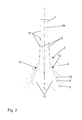
- Fig. 2
- eine Ansicht des Schaufelfußes nach Fig. 1 mit dem durch die spezifische Faserlagenanordnung erzielten Übergangsbereich und der Druckspannungseinflusszone.
- Ein an ein nur teilweise dargestelltes Schaufelblatt 1 anschließender Schaufelfuß 2 ist in einer Ausnehmung 3 einer Rotorscheibe 4 angeordnet. Der Schaufelfuß 2 umfasst eine - sich im Schaufelblatt 1 fortsetzende - quasi-unidirektional verstärkte Kohlenstofffaser-Kunststoff-Tragstruktur 6, die aus einer mit Kunststoff infiltrierten Vielzahl aneinander liegender Kohlenstofffaserlagen 7 besteht. Die Kohlenstofffaserlagen 7 verlaufen über die gesamte Länge der Fanschaufel, das heißt, vom Schaufelblatt 1 bis zum Boden des Schaufelfußes 2, und zwar, wie Fig. 2 zeigt, zum Teil in eine sich zum Schaufelfuß 2 hin verjüngende Schaufelblattwurzel 14. Am Anfang der Schaufelblattwurzel 14 beginnt eine äußere kraftgerechte Übergangszone 15 (Soft-Transition-Zone) eines Übergangsbereiches 13, in der bereits die ersten - äußeren - Kohlenstofffaserlagen 7 zur Bildung des Schaufelfußes 2 mit einer bestimmten Krümmung nach außen abgelenkt werden, um aus der zur Schaufelblattachse parallelen Lage allmählich in eine zu den geradem Flanken 12 des Schaufelfußes 2 parallele Lage überzugehen. Der Übergangsradius der Kohlenstofffaserlagen 7 im Übergangsbereich 13 ist so gewählt, das keine kritischen Biegespannungen auftreten. Zur optimalen Lastübertragung in den Schaufelfuß 2 und zur Verminderung der Delaminationsneigung entspricht der Übergang in der äußeren kraftgerechten Übergangszone 15 der Krümmung eines Teils einer Ellipse mit einem Ellipsenverhältnis von 3:1. In der im Schaufelfuß 2 ausgebildeten Druckspannungseinflusszone 11, in der die Faserlagen parallel zu den Flanken 5, 12 der Ausnehmung 3 bzw. des Schaufelfußes 2 verlaufen, erfolgt keine Umlenkung.
- Im Schaufelfuß 2, und zwar im Wesentlichen beschränkt auf den in der Ausnehmung 3 liegenden Teil, sind zwischen den Kunststofffaserlagen 7 Kohlenstofffaserzwischenschichten 8 angeordnet. Die Kohlenstofffaserzwischenschichten 8 sorgen für eine Auffächerung der Kohlenstofffaserlagen 7 entsprechend der Geometrie des Schaufelfußes 2 und verhindern die Ausbildung harzreicher Stellen bei der Kunststoffinfiltration, so dass eine Festigkeitsreduzierung und Steifigkeitssprünge in diesem Bereich verhindert werden. Die Kohlenstofffaserzwischenschichten 8 sind in der Länge unterschiedlich dimensioniert, und zwar so, dass die Kohlenstofffaserlagen 7 und die Kohlenstofffaserzwischenschichten 8 in der Druckspannungseinflusszone 11 parallel zu den Flanken 12 des Schaufelfußes 2 verlaufen, um so die - begrenzte - Druckfestigkeit der Kohlenstofffaserlagen und -zwischenschichten in vollem Umfang auszunutzen.
- An den Außenflächen der quasi-unidirektionalen Kohlenstofffaser-Kunststoff-Tragstruktur 6 befindet sich eine +/-45°-Kohlenstofffaserschicht 9, deren Faserrichtung im Winkel von +45° und -45° zur Faserrichtung der Kohlenstofffaser-Kunststoff-Tragstruktur 6 verläuft. Die +/-45°-Kohlenstofffaserschicht 9 dient zur Verbesserung der Krafteinleitung in die quasi-unidirektional verstärkte Kohlenstofffaser-Kunststoff-Tragschicht 6.
- Die Flanken 12 des Schaufelfußes 2 sind schließlich jeweils mit einer Glasfaseraußenschicht 10 abgedeckt, die über die durch die parallelen Faserlagen gebildete Druckspannungseinflusszone 11 hinaus bis in den Übergangsbereich 13 reicht. Die Stärke der Glasfaseraußenschicht 10 nimmt im Übergangsbereich allmählich ab, um ein vorzeitiges Ablösen der Flanke in der Übergangszone 15, hervorgerufen durch das Nachgeben des Schaufelfußes 2 infolge der hohen Druckbeanspruchung, zu verhindern.
- Ein Ablösen im Bereich der Flanken 12 und eine Delamination im Übergangsbereich 13 können zusätzlich noch dadurch verhindert werden, dass die Kohlenstofffaserlagen 7 im Übergangsbereich 13 in Dickenrichtung durch gespitzte Kohlenstofffaserkunststoffstifte (nicht dargestellt) verstärkt werden.
- Die Herstellung der aus einem Textilverbundwerkstoff bestehenden Fanschaufel erfolgt durch Einlegen der Vielzahl der oben beschriebenen Faserlagen 7 bis 10 und -stifte in der oben angegebenen Anordnung in ein Formwerkzeug, wobei in das geschlossene Formwerkzeug anschließend unter Druck ein Kunstharz infiltriert wird. Während der Kunstharzinfiltration wird jedoch am Schaufelfußes 2 im Bereich der Flanken 12 bzw. der Druckspannungseinflusszone 11 ein lokaler Druck aufgebracht, der größer als der Infiltrationsdruck des Kunstharzes ist und gegen diesen wirkt, so dass die Faserlagen im Schaufelfuß zur Gewährleistung einer effizienten Druckübertragung in diesem Bereich dicht aufeinander liegen. Während der infiltrierte Schaufelbereich bereits die erforderliche Oberflächenstruktur aufweist, wird die Oberfläche des während der Herstellung unmittelbar mit einem Druckmittel beaufschlagten Schaufelfußes 2 anschließend noch mechanisch bearbeitet.
-
- 1
- Schaufelblatt
- 2
- Schaufelfuß
- 3
- Ausnehmung in 4
- 4
- Rotorscheibe
- 5
- Flanke v. 3
- 6
- Kohlenstofffaser-Kunststoff-Tragstruktur
- 7
- Kohlenstofffaserlagen v. 6
- 8
- Kohlenstofffaserzwischenschichten
- 9
- +/-45°-Kohlenstofffaserschichten
- 10
- Glasfaseraußenschicht
- 11
- Druckspannungseinflusszone
- 12
- Flanken v. 2
- 13
- Übergangsbereich
- 14
- Schaufelblattwurzel
- 15
- äußere kraftgerechte Übergangszone v. 13
Claims (8)
- Fanschaufel aus Textilverbundwerkstoff für das Gebläse eines Gasturbinentriebwerks, die ein Schaufelblatt (1) und einen in einer Ausnehmung (3) einer Rotorscheibe (4) gehaltenen Schaufelfuß (2)umfasst, gekennzeichnet durch- eine Vielzahl parallel zur Schaufelblattachse verlaufender, eine quasi-unidirektional verstärkte Kohlenstofffaser-Kunststoff-Tragstruktur (6) bildender Kohlenstofffaserlagen (7), die- die eine sich im Schaufelfuß (2) verjüngende Schaufelblattwurzel (14),- einen vom Anfang der Schaufelblattwurzel (14) beidseitig ausgehenden Übergangsbereich (13), in dem die Kohlenstofffaserlagen (7) von der zur Schaufelblattachse parallelen Lage über eine äußere kraftgerechte Übergangszone (15) in eine entsprechend der Geometrie des Schaufelfußes (2) aufgefächerte Lage umgelenkt werden, und- eine Druckspannungseinflusszone (11), in der die zuvor umgelenkten Kohlenstofffaserlagen (7) parallel zu den in der Ausnehmung (3) der Rotorscheibe liegenden Flanken (12) des Schaufelfußes (2) verlaufen,bilden, wobei- zwischen den aufgefächerten Kohlenstofffaserlagen (7) jeweils Kohlenstofffaserzwischenschichten (8), und- auf den beiden Flanken (12) des Schaufelfußes (2) jeweils eine Glasfaseraußenschicht (10) angeordnet sind.
- Fanschaufel nach Anspruch 1, dadurch gekennzeichnet, dass an den gegenüberliegenden Seitenflächen der Schaufel jeweils eine zwischen der Tragstruktur (6) und der Glasfaseraußenschicht (10) liegende +/- 5°-Kohlenstofffaserschicht (9) angeordnet ist.
- Fanschaufel nach Anspruch 1 oder 2, dadurch gekennzeichnet, dass die Glasfaseraußenschicht (10) entlang der Flanken (12) des Schaufelfußes (2) bis zum Übergangsbereich (13) verläuft.
- Fanschaufel nach Anspruch 3, dadurch gekennzeichnet, dass die Glasfaseraußenschicht (10) in der kraftgerechten Übergangszone (15) mit abnehmender Schichtdicke allmählich ausläuft.
- Fanschaufel nach Anspruch 1, durch gekennzeichnet, dass der Umlenkungsradius der Faserlagen in der Übergangszone (15) dem Kurvenverlauf einer Ellipse mit einem Ellipsenverhältnis von 3:1 entspricht.
- Fanschaufel nach Anspruch 1, dadurch gekennzeichnet, dass die Kohlenstofffaserzwischenschichten (8) entsprechend der Geometrie der Druckspannungseinflusszone (11) unterschiedlich weit und mit sich verjüngender Schichtdicke in den Übergangsbereich (13) hinein verlaufen.
- Fanschaufel nach einem der Ansprüche 1 bis 6, dadurch gekennzeichnet, dass die Kohlenstofffaserlagen (7) im Übergangsbereich (13) in Dickenrichtung durch gespitzte Glas- oder Kohlenstofffaserkunststoffstifte verstärkt sind.
- Fanschaufel nach einem der Ansprüche 1 bis 7, dadurch gekennzeichnet, dass der Kunststoffanteil zwischen den Faserlagen in der Druckspannungseinflusszone aufgrund eines in diesem Bereich während der Kunststoffinfiltration aufgebrachten erhöhten lokalen Drucks und einer stärkeren Verdichtung der Faserlagen geringer als in den nicht lokal druckbeaufschlagten Schaufelbereichen ist.
Applications Claiming Priority (1)
| Application Number | Priority Date | Filing Date | Title |
|---|---|---|---|
| DE102006049818A DE102006049818A1 (de) | 2006-10-18 | 2006-10-18 | Fanschaufel aus Textilverbundwerkstoff |
Publications (3)
| Publication Number | Publication Date |
|---|---|
| EP1914383A2 true EP1914383A2 (de) | 2008-04-23 |
| EP1914383A3 EP1914383A3 (de) | 2010-12-29 |
| EP1914383B1 EP1914383B1 (de) | 2016-06-08 |
Family
ID=38610644
Family Applications (1)
| Application Number | Title | Priority Date | Filing Date |
|---|---|---|---|
| EP07117952.7A Not-in-force EP1914383B1 (de) | 2006-10-18 | 2007-10-05 | Fanschaufel aus Textilverbundwerkstoff |
Country Status (3)
| Country | Link |
|---|---|
| US (1) | US8100662B2 (de) |
| EP (1) | EP1914383B1 (de) |
| DE (1) | DE102006049818A1 (de) |
Cited By (8)
| Publication number | Priority date | Publication date | Assignee | Title |
|---|---|---|---|---|
| WO2011005337A1 (en) * | 2009-07-08 | 2011-01-13 | General Electric Company | Composite turbine nozzle segment |
| EP2149711A3 (de) * | 2008-07-31 | 2014-06-18 | General Electric Company | Herstellungsverfahren für eine Gebläseschaufel einer Strömungsmaschine |
| WO2014135798A1 (fr) * | 2013-03-07 | 2014-09-12 | Snecma | Insert fibreux destine a combler un espace vide d'une preforme fibreuse pour la fabrication d'une piece en materiau composite de turbomachine |
| EP2423440A3 (de) * | 2010-08-24 | 2014-12-24 | United Technologies Corporation | Fußbereich einer Schaufel für einen Gasturbinenmotor |
| EP2904255A4 (de) * | 2012-10-01 | 2015-12-02 | United Technologies Corp | Getriebeturbolüfter mit lüfterrotor mit hoher leistungsintensität |
| CN108757270A (zh) * | 2018-07-10 | 2018-11-06 | 江苏新扬新材料股份有限公司 | 一体化成型复合材料桨叶结构 |
| EP3736116A1 (de) * | 2019-05-09 | 2020-11-11 | The Boeing Company | Verbundstruktur mit einem variablen mass und verfahren zur formung einer verbundstruktur mit einem variablen mass |
| EP3736117A1 (de) * | 2019-05-09 | 2020-11-11 | The Boeing Company | Verbundstruktur mit einem variablen mass und verfahren zur formung einer verbundstruktur mit einem variablen mass |
Families Citing this family (53)
| Publication number | Priority date | Publication date | Assignee | Title |
|---|---|---|---|---|
| US9488059B2 (en) * | 2009-08-05 | 2016-11-08 | Hamilton Sundstrand Corporation | Fan blade dovetail with compliant layer |
| DE102009047799B4 (de) * | 2009-09-30 | 2015-05-28 | Siemens Aktiengesellschaft | Turbinenschaufel, Turbinenwelle, Turbinenanlage und Verfahren zur Montage der Turbinenschaufel |
| US20110229334A1 (en) * | 2010-03-16 | 2011-09-22 | United Technologies Corporation | Composite leading edge sheath and dovetail root undercut |
| US9556742B2 (en) | 2010-11-29 | 2017-01-31 | United Technologies Corporation | Composite airfoil and turbine engine |
| FR2970943B1 (fr) | 2011-01-31 | 2014-02-28 | Eurocopter France | Pale et procede de fabrication de ladite pale |
| US8740571B2 (en) * | 2011-03-07 | 2014-06-03 | General Electric Company | Turbine bucket for use in gas turbine engines and methods for fabricating the same |
| CN103429909B (zh) * | 2011-03-09 | 2017-04-05 | 株式会社Ihi | 导流叶片安装结构及风扇 |
| JP5967883B2 (ja) * | 2011-09-05 | 2016-08-10 | 三菱日立パワーシステムズ株式会社 | 回転機械翼 |
| US9248612B2 (en) | 2011-12-15 | 2016-02-02 | General Electric Company | Containment case and method of manufacture |
| JP5982837B2 (ja) * | 2012-01-30 | 2016-08-31 | 株式会社Ihi | 航空機用ジェットエンジンのファン動翼 |
| US9810077B2 (en) | 2012-01-31 | 2017-11-07 | United Technologies Corporation | Fan blade attachment of gas turbine engine |
| US20150192023A1 (en) * | 2012-06-08 | 2015-07-09 | Nicholas Joseph Kray | Mechanical Interlock Feature for Multi-Material Airfoils |
| US10633985B2 (en) * | 2012-06-25 | 2020-04-28 | General Electric Company | System having blade segment with curved mounting geometry |
| US10519788B2 (en) | 2013-05-29 | 2019-12-31 | General Electric Company | Composite airfoil metal patch |
| US10774660B2 (en) | 2013-10-14 | 2020-09-15 | Raytheon Technologies Corporation | Blade wedge attachment lay-up |
| CN105899762B (zh) | 2014-01-16 | 2017-11-07 | 通用电气公司 | 复合叶根应力消除衬垫 |
| DE102014210025A1 (de) * | 2014-05-26 | 2015-12-17 | Rolls-Royce Deutschland Ltd & Co Kg | Schubumkehrkaskadenelement einer Fluggasturbine |
| US10174624B1 (en) * | 2014-06-05 | 2019-01-08 | United Technologies Corporation | Composite blade root lay-up |
| DE102015223404B4 (de) * | 2015-11-26 | 2019-01-31 | Airbus Defence and Space GmbH | Zugprobe, Verfahren zum Herstellen einer Zugprobe, Vorrichtung zur Durchführung eines Zugversuchs und Verfahren zur Durchführung eines Zugversuchs |
| GB2548113B (en) * | 2016-03-08 | 2019-01-02 | Rolls Royce Plc | A composite component |
| US10677259B2 (en) | 2016-05-06 | 2020-06-09 | General Electric Company | Apparatus and system for composite fan blade with fused metal lead edge |
| GB2550393A (en) * | 2016-05-19 | 2017-11-22 | Rolls Royce Plc | A composite component |
| US11383494B2 (en) * | 2016-07-01 | 2022-07-12 | General Electric Company | Ceramic matrix composite articles having different localized properties and methods for forming same |
| US10443409B2 (en) * | 2016-10-28 | 2019-10-15 | Rolls-Royce North American Technologies Inc. | Turbine blade with ceramic matrix composite material construction |
| US10577939B2 (en) * | 2016-11-01 | 2020-03-03 | Rolls-Royce Corporation | Turbine blade with three-dimensional CMC construction elements |
| JP6778147B2 (ja) * | 2017-05-31 | 2020-10-28 | 三菱重工業株式会社 | 複合材料翼及び複合材料翼の製造方法 |
| JPWO2019131893A1 (ja) * | 2017-12-28 | 2020-12-24 | 国立大学法人 東京大学 | 複合材料、積層構造体、航空機の翼及び複合材料の製造方法 |
| US11931981B2 (en) | 2018-01-29 | 2024-03-19 | General Electric Company | Reinforced composite blade and method of making a blade |
| JP6745832B2 (ja) | 2018-03-29 | 2020-08-26 | 三菱重工業株式会社 | 複合材料翼および複合材料翼の製造方法 |
| JP6738850B2 (ja) * | 2018-03-29 | 2020-08-12 | 三菱重工業株式会社 | 複合材料翼および複合材料翼の製造方法 |
| US11346363B2 (en) | 2018-04-30 | 2022-05-31 | Raytheon Technologies Corporation | Composite airfoil for gas turbine |
| GB201808939D0 (en) * | 2018-05-31 | 2018-07-18 | Rolls Royce Plc | Composite fan blade root |
| GB201811103D0 (en) * | 2018-07-06 | 2018-08-22 | Rolls Royce Plc | An aerofoil structure and a method of manufacturing an aerofoil structure for a gas turbine engine |
| US11434781B2 (en) | 2018-10-16 | 2022-09-06 | General Electric Company | Frangible gas turbine engine airfoil including an internal cavity |
| US10760428B2 (en) | 2018-10-16 | 2020-09-01 | General Electric Company | Frangible gas turbine engine airfoil |
| US11111815B2 (en) | 2018-10-16 | 2021-09-07 | General Electric Company | Frangible gas turbine engine airfoil with fusion cavities |
| US10837286B2 (en) | 2018-10-16 | 2020-11-17 | General Electric Company | Frangible gas turbine engine airfoil with chord reduction |
| US10746045B2 (en) | 2018-10-16 | 2020-08-18 | General Electric Company | Frangible gas turbine engine airfoil including a retaining member |
| US11149558B2 (en) | 2018-10-16 | 2021-10-19 | General Electric Company | Frangible gas turbine engine airfoil with layup change |
| JP7236337B2 (ja) * | 2019-06-19 | 2023-03-09 | 三菱重工業株式会社 | 複合材翼及び複合材翼の成形方法 |
| FR3113420B1 (fr) * | 2020-08-17 | 2022-10-21 | Safran | Aube composite de turbomachine d’aeronef |
| US11492915B2 (en) * | 2020-12-17 | 2022-11-08 | Raytheon Technologies Corporation | Turbine with reduced burst margin |
| FR3123378B1 (fr) * | 2021-05-27 | 2023-05-26 | Safran Aircraft Engines | Embuvage différencié des torons du renfort fibreux d’une aube de soufflante |
| US12116903B2 (en) | 2021-06-30 | 2024-10-15 | General Electric Company | Composite airfoils with frangible tips |
| US11674399B2 (en) | 2021-07-07 | 2023-06-13 | General Electric Company | Airfoil arrangement for a gas turbine engine utilizing a shape memory alloy |
| US11668317B2 (en) | 2021-07-09 | 2023-06-06 | General Electric Company | Airfoil arrangement for a gas turbine engine utilizing a shape memory alloy |
| CN114458949B (zh) * | 2022-01-20 | 2024-08-06 | 北京海神动力科技有限公司 | 液氢航空发动机 |
| US11846204B2 (en) * | 2022-03-18 | 2023-12-19 | Rtx Corporation | CMC blade with damage tolerant edges |
| US12253006B2 (en) * | 2022-12-27 | 2025-03-18 | General Electric Company | Composite airfoil assembly having a dovetail portion |
| GB2639409A (en) * | 2023-01-16 | 2025-09-24 | Ihi Corp | Composite blade |
| US12163445B1 (en) * | 2023-06-29 | 2024-12-10 | General Electric Company | Composite airfoil assembly having a dovetail |
| US12173622B1 (en) | 2023-10-13 | 2024-12-24 | Rtx Corporation | Composite blade with tapered root section |
| US20250198292A1 (en) * | 2023-12-15 | 2025-06-19 | Rtx Corporation | Blade configured for impact tolerance |
Citations (4)
| Publication number | Priority date | Publication date | Assignee | Title |
|---|---|---|---|---|
| US3664764A (en) | 1969-07-18 | 1972-05-23 | Dowty Rotol Ltd | Devices of fibrous-reinforced plastics material |
| US4040770A (en) | 1975-12-22 | 1977-08-09 | General Electric Company | Transition reinforcement of composite blade dovetails |
| US5573377A (en) | 1995-04-21 | 1996-11-12 | General Electric Company | Assembly of a composite blade root and a rotor |
| DE10326719A1 (de) | 2003-06-06 | 2004-12-23 | Rolls-Royce Deutschland Ltd & Co Kg | Verdichterschaufelfuß für Triebwerksschaufeln von Flugzeugtriebwerken |
Family Cites Families (10)
| Publication number | Priority date | Publication date | Assignee | Title |
|---|---|---|---|---|
| US3123841A (en) * | 1964-03-10 | Telescoping folding boats | ||
| BE550839A (de) * | 1954-10-25 | |||
| US3679324A (en) * | 1970-12-04 | 1972-07-25 | United Aircraft Corp | Filament reinforced gas turbine blade |
| CH536183A (de) | 1971-09-17 | 1973-04-30 | Bbc Brown Boveri & Cie | Verfahren zur Herstellung einer Schaufel für Strömungsmaschinen |
| US3752600A (en) * | 1971-12-09 | 1973-08-14 | United Aircraft Corp | Root pads for composite blades |
| GB1536899A (en) * | 1977-09-06 | 1978-12-29 | Rolls Royce | Fibre reinforced composite structures |
| US4363602A (en) | 1980-02-27 | 1982-12-14 | General Electric Company | Composite air foil and disc assembly |
| US5375978A (en) * | 1992-05-01 | 1994-12-27 | General Electric Company | Foreign object damage resistant composite blade and manufacture |
| DE19724523C1 (de) | 1997-06-11 | 1998-06-04 | Haweka Gmbh | Schnellspannmutter zum Aufspannen der Felge eines Fahrzeugrades auf einem mit einem Außengewinde versehenen Ende einer Welle einer Auswuchtmaschine |
| US6290466B1 (en) * | 1999-09-17 | 2001-09-18 | General Electric Company | Composite blade root attachment |
-
2006
- 2006-10-18 DE DE102006049818A patent/DE102006049818A1/de not_active Withdrawn
-
2007
- 2007-10-05 EP EP07117952.7A patent/EP1914383B1/de not_active Not-in-force
- 2007-10-18 US US11/907,958 patent/US8100662B2/en not_active Expired - Fee Related
Patent Citations (4)
| Publication number | Priority date | Publication date | Assignee | Title |
|---|---|---|---|---|
| US3664764A (en) | 1969-07-18 | 1972-05-23 | Dowty Rotol Ltd | Devices of fibrous-reinforced plastics material |
| US4040770A (en) | 1975-12-22 | 1977-08-09 | General Electric Company | Transition reinforcement of composite blade dovetails |
| US5573377A (en) | 1995-04-21 | 1996-11-12 | General Electric Company | Assembly of a composite blade root and a rotor |
| DE10326719A1 (de) | 2003-06-06 | 2004-12-23 | Rolls-Royce Deutschland Ltd & Co Kg | Verdichterschaufelfuß für Triebwerksschaufeln von Flugzeugtriebwerken |
Cited By (13)
| Publication number | Priority date | Publication date | Assignee | Title |
|---|---|---|---|---|
| EP2149711A3 (de) * | 2008-07-31 | 2014-06-18 | General Electric Company | Herstellungsverfahren für eine Gebläseschaufel einer Strömungsmaschine |
| WO2011005337A1 (en) * | 2009-07-08 | 2011-01-13 | General Electric Company | Composite turbine nozzle segment |
| US8206096B2 (en) | 2009-07-08 | 2012-06-26 | General Electric Company | Composite turbine nozzle |
| EP2423440A3 (de) * | 2010-08-24 | 2014-12-24 | United Technologies Corporation | Fußbereich einer Schaufel für einen Gasturbinenmotor |
| EP2904255A4 (de) * | 2012-10-01 | 2015-12-02 | United Technologies Corp | Getriebeturbolüfter mit lüfterrotor mit hoher leistungsintensität |
| WO2014135798A1 (fr) * | 2013-03-07 | 2014-09-12 | Snecma | Insert fibreux destine a combler un espace vide d'une preforme fibreuse pour la fabrication d'une piece en materiau composite de turbomachine |
| CN108757270A (zh) * | 2018-07-10 | 2018-11-06 | 江苏新扬新材料股份有限公司 | 一体化成型复合材料桨叶结构 |
| CN108757270B (zh) * | 2018-07-10 | 2024-01-09 | 江苏新扬新材料股份有限公司 | 一体化成型复合材料桨叶结构 |
| EP3736116A1 (de) * | 2019-05-09 | 2020-11-11 | The Boeing Company | Verbundstruktur mit einem variablen mass und verfahren zur formung einer verbundstruktur mit einem variablen mass |
| EP3736117A1 (de) * | 2019-05-09 | 2020-11-11 | The Boeing Company | Verbundstruktur mit einem variablen mass und verfahren zur formung einer verbundstruktur mit einem variablen mass |
| US10913215B2 (en) | 2019-05-09 | 2021-02-09 | The Boeing Company | Composite structure having a variable gage and methods for forming a composite structure having a variable gage |
| US10919260B2 (en) | 2019-05-09 | 2021-02-16 | The Boeing Company | Composite structure having a variable gage and methods for forming a composite structure having a variable gage |
| EP4086067A1 (de) * | 2019-05-09 | 2022-11-09 | The Boeing Company | Verbundstruktur mit einem variablen mass und verfahren zur formung einer verbundstruktur mit einem variablen mass |
Also Published As
| Publication number | Publication date |
|---|---|
| US20080187441A1 (en) | 2008-08-07 |
| DE102006049818A1 (de) | 2008-04-24 |
| EP1914383B1 (de) | 2016-06-08 |
| US8100662B2 (en) | 2012-01-24 |
| EP1914383A3 (de) | 2010-12-29 |
Similar Documents
| Publication | Publication Date | Title |
|---|---|---|
| EP1914383B1 (de) | Fanschaufel aus Textilverbundwerkstoff | |
| EP1450006B1 (de) | Verdichterschaufel für ein Flugzeugtriebwerk | |
| DE102005059298C5 (de) | System und Verfahren zur passiven Lastminderung bei einer Windturbine | |
| EP0019691B1 (de) | Aus einzelnen Abschnitten gefertigtes Rotorblatt | |
| EP2731772B1 (de) | Verfahren zum herstellen eines rotorblatts für eine windenergieanlage | |
| DE2642038C2 (de) | Schaufel für Strömungsmaschinen | |
| DE69222197T2 (de) | Bläserschaufel mit grosser Sehnenlänge | |
| EP2363599B2 (de) | Rotorblatt für eine Windenergieanlage, Windenergieanlage und Verfahren zum Herstellen eines Rotorblatts | |
| EP0737814B1 (de) | Verdichter | |
| DE102010017062B4 (de) | Rotorblatt einer Windkraftanlage | |
| EP2287447B1 (de) | Thermoplastenendstufenschaufel und Verfahren zur Herstellung | |
| EP2815861B1 (de) | Verfahren und Formwerkzeug zur Herstellung eines Gurtsegments für ein Windenergieanlagenrotorblatt | |
| EP1398499A1 (de) | Befestigung von Rotorblättern an der Nabe einer Windenergieanlage | |
| EP1939402A2 (de) | Fanschaufel aus Verbundwerkstoff für ein Gasturbinentriebwerk | |
| DE102007036917A1 (de) | Rotorblatt für Windkraftanlagen, insbesondere für schwimmende Windkraftanlagen, sowie Windkraftanlage mit einem Rotorblatt | |
| EP3396155B1 (de) | Rotorblatt einer windenergieanlage, verfahren zum herstellen eines solchen und verwendung eines abschlussstegs | |
| EP3054179A1 (de) | Welle eines gasturbinentriebwerks in faserverbundbauweise | |
| DE102011017460A1 (de) | Faserverbundbauteil, Flügelspitzenverlängerung und Flugzeug mit einem Faserverbundteil | |
| DE2645174A1 (de) | Rotorkopf fuer einen schlag- und schwenkgelenklosen rotor | |
| EP3551438B1 (de) | Hinterkantengurt eines rotorblatts einer windenergieanlage, rotorblatt und verfahren zum herstellen eines hinterkantengurts | |
| EP3994351B1 (de) | Rotorblatt für eine windenergieanlage, rotorblattsegment, windenergieanlage und verfahren zur herstellung eines rotorblattes | |
| EP1780407A2 (de) | Rotorblatt für Windkraftanlagen | |
| EP3564523B1 (de) | Flanschanschluss für ein windenergieanlagenrotorblatt, versteifungslage für einen flanschanschluss, flanscheinleger, windenergieanlagenrotorblatt, windenergieanlage sowie verfahren zum herstellen eines flanschanschlusses | |
| EP2436878B1 (de) | Koppelbolzen für Turbinenschaufeln | |
| DE102009047799B4 (de) | Turbinenschaufel, Turbinenwelle, Turbinenanlage und Verfahren zur Montage der Turbinenschaufel |
Legal Events
| Date | Code | Title | Description |
|---|---|---|---|
| PUAI | Public reference made under article 153(3) epc to a published international application that has entered the european phase |
Free format text: ORIGINAL CODE: 0009012 |
|
| AK | Designated contracting states |
Kind code of ref document: A2 Designated state(s): AT BE BG CH CY CZ DE DK EE ES FI FR GB GR HU IE IS IT LI LT LU LV MC MT NL PL PT RO SE SI SK TR |
|
| AX | Request for extension of the european patent |
Extension state: AL BA HR MK RS |
|
| PUAL | Search report despatched |
Free format text: ORIGINAL CODE: 0009013 |
|
| AK | Designated contracting states |
Kind code of ref document: A3 Designated state(s): AT BE BG CH CY CZ DE DK EE ES FI FR GB GR HU IE IS IT LI LT LU LV MC MT NL PL PT RO SE SI SK TR |
|
| AX | Request for extension of the european patent |
Extension state: AL BA HR MK RS |
|
| 17P | Request for examination filed |
Effective date: 20110523 |
|
| AKX | Designation fees paid |
Designated state(s): DE FR GB |
|
| RIN1 | Information on inventor provided before grant (corrected) |
Inventor name: HUFENBACH, WERNER, PROF. DR.-ING Inventor name: LANGKAMP, ALBERT, DR.-ING. Inventor name: SCHREIBER, KARL Inventor name: EBERT, CHRISTOPH, DIPL.-ING. |
|
| RIN1 | Information on inventor provided before grant (corrected) |
Inventor name: HUFENBACH, WERNER, PROF. DR.-ING Inventor name: SCHREIBER, KARL Inventor name: EBERT, CHRISTOPH, DIPL.-ING. Inventor name: LANGKAMP, ALBERT, DR.-ING. |
|
| RIN1 | Information on inventor provided before grant (corrected) |
Inventor name: EBERT, CHRISTOPH, DIPL.-ING. Inventor name: SCHREIBER, KARL Inventor name: HUFENBACH, WERNER, PROF. DR.-ING Inventor name: LANGKAMP, ALBERT, DR.-ING. |
|
| GRAP | Despatch of communication of intention to grant a patent |
Free format text: ORIGINAL CODE: EPIDOSNIGR1 |
|
| RIC1 | Information provided on ipc code assigned before grant |
Ipc: F01D 5/30 20060101ALI20160210BHEP Ipc: F01D 5/14 20060101ALI20160210BHEP Ipc: F01D 5/28 20060101AFI20160210BHEP |
|
| INTG | Intention to grant announced |
Effective date: 20160229 |
|
| GRAS | Grant fee paid |
Free format text: ORIGINAL CODE: EPIDOSNIGR3 |
|
| GRAA | (expected) grant |
Free format text: ORIGINAL CODE: 0009210 |
|
| AK | Designated contracting states |
Kind code of ref document: B1 Designated state(s): DE FR GB |
|
| REG | Reference to a national code |
Ref country code: GB Ref legal event code: FG4D Free format text: NOT ENGLISH |
|
| REG | Reference to a national code |
Ref country code: DE Ref legal event code: R096 Ref document number: 502007014871 Country of ref document: DE |
|
| REG | Reference to a national code |
Ref country code: FR Ref legal event code: PLFP Year of fee payment: 10 |
|
| REG | Reference to a national code |
Ref country code: DE Ref legal event code: R097 Ref document number: 502007014871 Country of ref document: DE |
|
| PLBE | No opposition filed within time limit |
Free format text: ORIGINAL CODE: 0009261 |
|
| STAA | Information on the status of an ep patent application or granted ep patent |
Free format text: STATUS: NO OPPOSITION FILED WITHIN TIME LIMIT |
|
| 26N | No opposition filed |
Effective date: 20170309 |
|
| REG | Reference to a national code |
Ref country code: FR Ref legal event code: PLFP Year of fee payment: 11 |
|
| REG | Reference to a national code |
Ref country code: FR Ref legal event code: PLFP Year of fee payment: 12 |
|
| PGFP | Annual fee paid to national office [announced via postgrant information from national office to epo] |
Ref country code: DE Payment date: 20191029 Year of fee payment: 13 |
|
| PGFP | Annual fee paid to national office [announced via postgrant information from national office to epo] |
Ref country code: FR Payment date: 20191025 Year of fee payment: 13 |
|
| PGFP | Annual fee paid to national office [announced via postgrant information from national office to epo] |
Ref country code: GB Payment date: 20191028 Year of fee payment: 13 |
|
| REG | Reference to a national code |
Ref country code: DE Ref legal event code: R119 Ref document number: 502007014871 Country of ref document: DE |
|
| GBPC | Gb: european patent ceased through non-payment of renewal fee |
Effective date: 20201005 |
|
| PG25 | Lapsed in a contracting state [announced via postgrant information from national office to epo] |
Ref country code: FR Free format text: LAPSE BECAUSE OF NON-PAYMENT OF DUE FEES Effective date: 20201031 Ref country code: DE Free format text: LAPSE BECAUSE OF NON-PAYMENT OF DUE FEES Effective date: 20210501 |
|
| PG25 | Lapsed in a contracting state [announced via postgrant information from national office to epo] |
Ref country code: GB Free format text: LAPSE BECAUSE OF NON-PAYMENT OF DUE FEES Effective date: 20201005 |