EP1913493B1 - Object association in a computer generated drawing environment - Google Patents
Object association in a computer generated drawing environment Download PDFInfo
- Publication number
- EP1913493B1 EP1913493B1 EP06801360.6A EP06801360A EP1913493B1 EP 1913493 B1 EP1913493 B1 EP 1913493B1 EP 06801360 A EP06801360 A EP 06801360A EP 1913493 B1 EP1913493 B1 EP 1913493B1
- Authority
- EP
- European Patent Office
- Prior art keywords
- target
- suggested
- subject
- association
- command
- Prior art date
- Legal status (The legal status is an assumption and is not a legal conclusion. Google has not performed a legal analysis and makes no representation as to the accuracy of the status listed.)
- Active
Links
- 238000000034 method Methods 0.000 claims description 58
- 230000000007 visual effect Effects 0.000 claims description 17
- 230000008569 process Effects 0.000 description 20
- 238000010586 diagram Methods 0.000 description 5
- 230000008859 change Effects 0.000 description 4
- 238000004891 communication Methods 0.000 description 2
- 230000004048 modification Effects 0.000 description 2
- 238000012986 modification Methods 0.000 description 2
- 230000004044 response Effects 0.000 description 2
- 238000012360 testing method Methods 0.000 description 2
- 241000220317 Rosa Species 0.000 description 1
- 230000005540 biological transmission Effects 0.000 description 1
- 238000004883 computer application Methods 0.000 description 1
- 238000012545 processing Methods 0.000 description 1
Images


Classifications
-
- G—PHYSICS
- G06—COMPUTING; CALCULATING OR COUNTING
- G06T—IMAGE DATA PROCESSING OR GENERATION, IN GENERAL
- G06T11/00—2D [Two Dimensional] image generation
- G06T11/60—Editing figures and text; Combining figures or text
-
- G—PHYSICS
- G06—COMPUTING; CALCULATING OR COUNTING
- G06F—ELECTRIC DIGITAL DATA PROCESSING
- G06F3/00—Input arrangements for transferring data to be processed into a form capable of being handled by the computer; Output arrangements for transferring data from processing unit to output unit, e.g. interface arrangements
- G06F3/01—Input arrangements or combined input and output arrangements for interaction between user and computer
- G06F3/048—Interaction techniques based on graphical user interfaces [GUI]
- G06F3/0484—Interaction techniques based on graphical user interfaces [GUI] for the control of specific functions or operations, e.g. selecting or manipulating an object, an image or a displayed text element, setting a parameter value or selecting a range
- G06F3/04845—Interaction techniques based on graphical user interfaces [GUI] for the control of specific functions or operations, e.g. selecting or manipulating an object, an image or a displayed text element, setting a parameter value or selecting a range for image manipulation, e.g. dragging, rotation, expansion or change of colour
-
- G—PHYSICS
- G06—COMPUTING; CALCULATING OR COUNTING
- G06F—ELECTRIC DIGITAL DATA PROCESSING
- G06F8/00—Arrangements for software engineering
- G06F8/30—Creation or generation of source code
- G06F8/34—Graphical or visual programming
Definitions
- connection line between two components (e.g., at a specific point in space). When one of the components moves, the connection line remains fixed in space and no longer connects the two components. Conversely, the glued connection places a line between two components and automatically adjusts the connection line so that the two components remain connected when one of the components is moved. If the user chooses the wrong type of connection for the type of drawing being made, the resulting drawing can be even more difficult to revise in the future.
- Visio® available from the Microsoft Corporation of Redmond, Washington, provides the user with the ability to cut, copy, or move drawing components, and/or the ability to select components from a master shape container or window. Additionally, Visio® provides a stamping tool which allows a shape to be selected and then dropped at various locations in a drawing by placing the pointer at the desired location and clicking on a mouse button. The stamping tool, however, does not suggest the placement of the shape and does not provide any connection between the shape dropped into the drawing and other pre-existing shapes.
- the user must decide precisely (e.g., the precise direction and distance) where to place the component and then manually connect the dropped shape to pre-existing shapes, if desired.
- the "Rational Rose 2002 tutorial” which can be found in the Internet: URL:http://cse.spsu.edu/sduggins/classes/Fall_2011/SWE 3623/Documents/Revised Rational_Rose2K_UML_2008032.pdf, discloses associating two objects in a drawing application with one another for two user-defined objects present on the drawing area of the drawing application and based on a single suggested graphical association.
- a computer implemented method can include designating a target object or shape in a drawing.
- the method can further include identifying a subject object or shape to be associated with the target object and providing a suggested association (e.g., placement and/or connection) of the subject object with the target object.
- the method can still further include receiving a command to accept the suggested association (and associating the subject with the target as suggested. Under certain circumstances, this method can allow one object to be placed and connected to another object quickly and easily by simply accepting a suggestion provided by the computing environment implementing the method.
- Embodiments of the invention are directed toward a method in a computing environment that includes receiving a command to designate a target and designating the target.
- the method can further include identifying a subject and providing at least two suggested associations of the subject with the target.
- the method can still further include receiving a command to accept a suggested association and associating the subject with the target as suggested.
- inventions are directed toward a method in a computing environment for associating two objects in a drawing application with one another, where the method includes receiving a command to designate a target object and designating the target object.
- the method can further include displaying at least two visual indicators identifying a direction relative to the target object and identifying a subject object.
- the method can still further include receiving a command to accept the direction identified by a visual indicator and placing the subject object relative to the target object in the direction identified by the visual indicator.
- the method can yet further include connecting the target object and the subject object with a connector object.
- the method can still further include removing the visual indicator.
- Still other embodiments of the invention are directed toward a computer-readable medium containing instructions for controlling a computing environment to perform a method that includes receiving a command to designate a target and designating the target.
- the method can further include identifying a subject and providing at least two suggested associations of the subject with the target.
- the method can still further include receiving a command to accept a suggested association and associating the subject with the target as suggested.
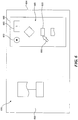
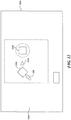
- FIG. 1 is a block diagram that illustrates a computing environment suitable for implementing a process for associating two objects in a drawing application with one another in accordance with embodiments of the invention.
- the computing environment 100 can include a computing or computer system 102 that can be operably connected or coupled to a display 104 and one or more input devices, for example, a keyboard 106a and a pointing device 106b (e.g., a mouse). Additionally, the computer system 102 can communicate with one or more storage devices (e.g., a hard drive 108 with one or more databases) and one or more devices 110 for reading other types of computer readable mediums (e.g., devices for reading disks 111).
- storage devices e.g., a hard drive 108 with one or more databases
- devices 110 for reading other types of computer readable mediums (e.g., devices for reading disks 111).
- the computer system 102 can also communicate via a network 112 (e.g., the Internet) with other devices or systems.
- a network 112 e.g., the Internet
- the computer system 102 can communicate with another computer system 114 and/or another database 116 via the network 112.
- the computing environment can have other arrangements, including more, fewer, and/or different components.
- the computing device or environment on which the system is implemented may include a central processing unit, memory, input devices (e.g., keyboard and pointing devices), output devices (e.g., display devices), and storage devices (e.g., disk drives).
- the memory and storage devices are computer-readable media that may contain instructions that implement the system.
- the data structures and message structures may be stored or transmitted via a data transmission medium, such as a signal on a communication link.
- Various communication links may be used, such as the Internet, a local area network, a wide area network, a point-to-point dial-up connection, a cell phone network, and so on.
- Embodiments of the system may be implemented in various operating environments that include personal computers, server computers, hand-held or laptop devices, multiprocessor systems, microprocessor-based systems, programmable consumer electronics, digital cameras, network PCs, minicomputers, mainframe computers, distributed computing environments that include any of the above systems or devices, and so on.
- the computer systems may be cell phones, personal digital assistants, smart phones, personal computers, programmable consumer electronics, digital cameras, and so on.
- the system may be described in the general context of computer-executable instructions, such as program modules, executed by one or more computers or other devices.
- program modules include routines, programs, objects, components, data structures, and so on that perform particular tasks or implement particular abstract data types.
- functionality of the program modules may be combined or distributed as desired in various embodiments.
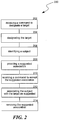
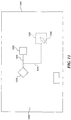
- FIG. 2 is a flow diagram that illustrates a process 200 for associating two objects in a drawing application with one another in accordance with various embodiments of the invention.
- the process can be carried out in a computing environment and can include receiving a command to designate a target (process portion 202) and designating the target (process portion 204).
- the method can further include identifying a subject (process portion 206).
- identifying a subject can include receiving a command (e.g., from a user) to designate a subject from one and more objects in a drawing area and/or an area separate from the drawing area, and designating the subject as commanded.
- identifying a subject can include suggesting a subject designation, receiving a command to accept the suggested subject designation, and designating the subject.
- the method can still further include providing two or more suggested associations of the subject with the target (process portion 208), receiving a command to accept one of the suggested associations (process portion 210), and associating the subject with the target as suggested by the accepted suggested association (process portion 212).
- the method can yet further include removing the one or more suggested associations (process portion 214).
- this process can provide a user with a quick, effective, and efficient process to create, place, and/or connect two objects in a drawing by accepting suggestions generated by the computing environment. This feature can be particularly useful in drawing applications that use relational shapes and/or symbols (e.g., process flow charts, logical network diagrams, physical network drawings, organizational charts, other hierarchy charts, and the like).
- Figures 3-14 illustrate selected embodiments of the invention.
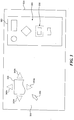
- Figure 3 is a partially schematic illustration of a display 304 having at least two suggested associations 340 of a subject object or subject 330 and a target object or target 320 in accordance with certain embodiments of the invention.
- one of the objects 365 in the window or area 360 has been identified as the subject 330, as indicated by the ghosted outline.
- the computing environment can receive a command from a user to designate the subject 330 from the object(s) 365 in the area 360 and can designate the subject 330 as commanded, thereby identifying the subject 330.
- the user designated the subject 330 by placing the cursor 350 proximate to the selected or desired object 365 by using a mouse and "clicking" a mouse button to designate the selected object 365 as the subject 330.
- other methods can be used to designate the subject 330, for example, by tabbing through a list with a keyboard and using the enter key to designate the subject 330.
- the identification of a subject 330 can also be indicated in other manners.
- the subject designation can be indicated by a color change, shading, reverse video, highlighting, of the like.
- the area 360 is separate from a drawing area 305 where the target drawing is being made (e.g., the drawing which has or will have the designated target 320) and includes a window or "container" with a list of objects 365.
- the associated object 365 can eventually be created, re-created, copied, moved, or placed in the drawing area 305 so that it can be associated with the target 320.
- the list of objects 365 can be represented in a different fashion, for example, a word list can be used to identify one or more objects 365.
- the area 360 can include another drawing or document (e.g., associated or unassociated with the current drawing application) and an object 365 can be identified as the subject 330 in a manner similar to that described above with reference to the "container" of objects.
- an object 365 in the drawing area 305 can be identified as the subject 330 using a similar process.
- the user has commanded the designation of the target 320 by hit testing a selected object or placing the cursor 350 proximate to (e.g., near or over) the selected object in the drawing area.
- the computing environment has received the command, designated the selected object as the target, and provided at least two suggested associations 340 of the subject 330 with the target 320.
- the suggested associations 340 are shown or displayed as visual indicators identifying a direction relative to the target 320.
- the suggested associations 340 or visual indicators can indicate a suggested direction for placing the subject 330 relative to the target 320 and/or extending a connector (e.g., for connecting the subject 330 to the target 320) away from the target.
- the suggested associations 340 are ghosted or subdued indicating that the user has not selected or accepted any of the suggested associations 340.
- the method can provide any number equal to or greater than two, or different kinds of suggested associations 340.
- suggested associations 340 are not provided for all objects in a drawing (e.g., when certain objects are hit tested no suggested associations 340 are provided). For example, in selected embodiments suggested associations 340 are not displayed for connector s and connectors cannot be designated as targets 320.
- FIG 4 the user has moved the cursor 350 proximate to the first suggested association 340a.
- the first suggested association 340 is no longer ghosted, indicating that the user has selected the first suggested association 340a, however, in the illustrated embodiment the user has not accepted the suggestion.
- the connector symbol 352 proximate to the cursor 350 indicates that the user can accept the selected suggested association 340 by entering an appropriate command, for example, by clicking a mouse button while the cursor 350 is proximate to the first suggested association 340a (e.g., using a "point and click" type scheme).
- the user can ignore or not accept the suggested associations 340 by not entering a command to accept the suggested associations 340.
- the user can then move the cursor 350 away from the selected object, use a different tool in the drawing application, or the like.
- other indications can be used to show that the user can accept one of the selected suggestions. For example, in selected embodiments there is no connector symbol 352 and the un-ghosting of a suggested association indicates that the user can accept the suggestion.
- other indicators can be used (e.g., the cursor 350 can change shape or color when the user can select a suggestion). In still other embodiments no indications are used.
- associating the subject 330 with the target 320 can include placing the subject 330 relative to the target 320 in a selected direction and/or connecting the target 320 with the subject 330 with a connector object or connector 370 (e.g., a line, a directional line, a ghosted line, a rectangular object, or the like).
- a connector object or connector 370 e.g., a line, a directional line, a ghosted line, a rectangular object, or the like.
- the subject 330 and the target 320 can be connected by a connector that extends away from the target in a direction that was indicated by the first suggested association 340a.
- the subject 330 can be associated with the target 320 in other ways and/or for other purposes.
- a circle or sphere can be placed around the subject 330 and target 320 to indicate that they are part of a selected grouping of items.
- animation can be used, for example, to provide additional feedback to the user.
- animation was used to show a copy of the subject 330 moving from the window 360 to its position in the drawing (as indicated by the ghosted symbols).
- the animation can show the subject 330 change in size as it moves from the window 360 to its position in the drawing and can then disappear.
- the animation can take other forms.
- the animation can simply show a series of dots moving from the position of the subject 330 in the window 360 to the position of the subject 330 in the drawing.
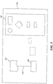
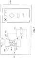
- Figure 6 is a partially schematic illustration of a display 604 where a user is commanding a designation of multiple subjects 630 in accordance with other embodiments of the invention.
- the user has designated an object 665 in an area 660 as a subject 630.
- the user has selected the multiple radio button 662 and entered the number 2 into the data field 663 to indicate that multiple (e.g., two) subjects 630 are being identified.
- the user commanded the designation of the associated object 665 by placing the cursor 650 proximate to the object and holding a mouse button down.
- the user can then move or "drag" the subjects 630 toward an object 665 in a drawing area 605 (e.g., by holding the mouse button down and moving the cursor 350).
- the cursor 650 has been positioned proximate to a selected object 665 in the drawing area, designating the selected object 665 as a target 620.
- the computing environment has provided (e.g., displayed) four suggested associations 640, shown as a first suggested association 640a, a second suggested association 640b, a third suggested association 640c, and a fourth suggested association 640d.
- the user has selected the first suggested association 640a by placing the cursor 650 proximate to the first suggested association 640a. Because the user has "dragged" the subjects 630 toward the target 620, the subjects 630 are also proximate to the first suggested association 640a.
- a small "+2" is displayed proximate to the subjects 630, indicating that the user has designated two subjects.
- other methods can be used to show multiple subjects (e.g., multiple symbols and/or overlapping shapes can be used to show multiple subjects).
- the computing environment also displays a preview of the association between the target 620 and the subjects(s) 630.
- the preview is shown in ghosted lines. Because another object 665 is connected to the target 620 with a first connector 670a extending away from the target 620 in the same direction as the first suggested association 640a, the preview shows the subjects 630 being positioned in the direction indicated by the first suggested association 640a, but a second connector 670b initially extends away from the target 620 in the direction of the second suggested association 640b.
- the computing environment can de-conflict the placement of the subject(s) 630 in other manners and/or using other priorities. For example, in other embodiments multiple connectors can be attached to a single side of the target 620.
- the user commands the acceptance of the first suggested association 640a by releasing the mouse button (that was held down to drag the subjects 630 toward the target 620) while the cursor 650 is proximate to the first suggested association 640a (e.g., using a "drag and drop" type scheme).
- the computing environment can associate the subject 630 with the target 620 as indicated by the first suggested association 640a.
- the subject 630 has been associated with the target 620, and a second connector 670b connects a first subject 630a to the target and a third connector 670c connects a second subject 630b to the target 620 via the first subject 630a and the second connector 670b.
- multiple subjects 630 can be connected to the target 620 in other manners.
- each multiple subject 630 can be connected directly to the target 620 (e.g., each with a separate dedicated connector 670) without any intervening subjects 630.
- multiple subjects can be identified in other manners and/or from other areas.
- objects can be identified using a keyboard (e.g., using the tab and enter keys).
- multiple subjects 630 can be identified using a point and click scheme.
- the user can use the mouse to point at each of multiple objects 665 and click a button on the mouse while holding down a shift key to identify the multiple subjects 630.
- the point and click scheme discussed above with reference to Figures 3-5 can then be used to accept a suggested association 640, thereby associating multiple subjects with the target.
- at least some of the subjects 630 can be selected from the drawing area 605.
- Figure 9 is a partially schematic illustration of a display 904 having at least two suggested associations 940 of a first subject 930a with a target 920 in accordance with still other embodiments of the invention.
- the first subject 930a has been identified from objects 965 in an area 960, as indicated by the ghosted lines surrounding the designated object 965.
- the subject(s) 930 can be selected from a drawing area 905 of the display 904.
- the user has positioned the cursor 950 proximate to an object in the drawing area 905, designating the associated object as the target 920.
- the computing environment has provided at least two suggested associations 940 between the first subject 930a and the target 920.
- the suggested associations 940 include a circle surrounded by four arrows, indicating that subject(s) 930 will be associated with the target 920 in a sequence determined by the computing environment. For example, in one embodiment a first subject will be connected to the right, a second subject will be connected to the left, etc. In other embodiments, other displays and/or logic can be used. For example, in other examples only one arrow is displayed at a time and that arrow indicates the specific direction the next associated subject 930 will be placed. Additionally, the logic can provide that the subject(s) 930 be associated with the target 920 in a different sequence (e.g., the first subject 930 can be placed below the target 920 instead of to the right).
- the user has commanded the acceptance of the suggested association 940 (e.g., by clicking a mouse button) and the first subject 930 has been connected to the right side of the target 920 with a first connector 970a.
- a second subject 930b has been selected.
- the cursor 950 is positioned proximate to an object, designating the object as the target 920 and the computing environment has provided a suggested association of the second subject 930b with the target 920.
- the suggested association 940 has been accepted and the second subject 930b has been connected to the second side of the target 920 with a second connector 970b.
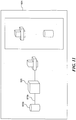
- Figure 12 is a partially schematic illustration of a display 1204 having at least two suggested associations 1240 of a subject 1230 with a target 1220 in accordance with yet other embodiments of the invention.
- a cursor 1250 has been place proximate to a first object in the drawing area 905, hit testing the first object.
- the computing environment searches within a selected area (indicated by the ghosted rectangle) to find the closest second object. If no object is found, then the first object is not designated as a target and no suggested associations are provided.
- the computing environment designates the first object as a target 1220, provides a suggested subject designation (e.g., a suggestion to designate the closest second object as a subject 1230), and provides at least two suggested associations 1240 of the suggested subject with the target 1220.
- a ghosted circle indicates the suggested subject designation.
- the size and shape of the search area can vary.
- the search area can be two or three times the width/height of the object that is hit tested.
- the search area can be the entire display or the entire document.
- the user has provided a command to accept the suggested subject designation and the computing environment has designated the associated object as the subject 1230, thereby identifying the subject 1230. Additionally, the user has commanded acceptance of the suggested association 1240 and the subject 1230 has been connected to the target 1220 with a connector 1270.
- the acceptance of the suggested subject designation and the suggested association can be accomplished with one user input. For example, in one embodiment the suggested subject designation and the suggested association can both be accepted by a single push of a button on a mouse. In other embodiments, separate commands can be used to accept the suggested subject designation and the suggested association. In still other embodiments, multiple suggested associations can be displayed and one of the multiple suggested associations can be selected after the subject has been identified.
- connection 1270 is a dynamic or "glued" connection. Accordingly, as the subject 1230 and/or the target 1220 are moved (e.g., relative to one another) the target 1220 and the subject 1230 remain connected (e.g., via modification of the connector 1270). In other embodiments, connections accomplished via the acceptance of a suggested association are not dynamic connections. In still other embodiments, the user can choose whether or not a dynamic connection is made in response to the acceptance of a suggested association.
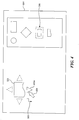
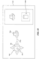
- Figure 14 is a partially schematic illustration of a three-dimensional display 1404 having at least two suggested associations 1440 of a target 1420 with a subject 1430 in accordance with yet other embodiments of the invention.
- the user has identified an object in the area 1460 as the subject 1430.
- the user has moved the subject 1430 (e.g., a copy of the object selected in area 1460) to a position proximate to a selected object in the drawing area 1405.
- the proximity of the cursor 1450 to the selected object in the drawing area 1405 has commanded the designation of the selected object as the target 1420.
- the computing environment has provided multiple suggested associations 1440 between the target 1420 and the subject 1430 in three-dimensions.
- a method in a computing environment for associating two objects in a drawing application with one another can include more, fewer, and/or different features. For example, in certain embodiments various features can be selected or deselected based on user preference or on the type of drawing or document that is selected (e.g., based on a template selection). In other embodiments, when visual indicators appear, their size, shape, and location relative to a designated target can change or be altered based on the proximity of adjacent objects in the drawing area.
Description
- Various computer applications are available that allow users to produce drawings using the computer. Many of these applications, however, are complex and complicated to use. For example, when a user is drawing or revising a process flow chart or a hierarchy chart, various drawing components must be created, placed relative to one another, and connected to provide context and meaning. The process of creating, placing, and connecting components can require multiple manual steps, and can be difficult, time consuming, and frustrating for the user.
- Additionally, in some circumstances, the user must choose between various types of connections, further complicating the process. For example, some applications provide both simple and glued connections. The simple connection places a connection line between two components (e.g., at a specific point in space). When one of the components moves, the connection line remains fixed in space and no longer connects the two components. Conversely, the glued connection places a line between two components and automatically adjusts the connection line so that the two components remain connected when one of the components is moved. If the user chooses the wrong type of connection for the type of drawing being made, the resulting drawing can be even more difficult to revise in the future.
- Various arrangements have been used to simplify the process of creating and placing components. For example, Visio®, available from the Microsoft Corporation of Redmond, Washington, provides the user with the ability to cut, copy, or move drawing components, and/or the ability to select components from a master shape container or window. Additionally, Visio® provides a stamping tool which allows a shape to be selected and then dropped at various locations in a drawing by placing the pointer at the desired location and clicking on a mouse button. The stamping tool, however, does not suggest the placement of the shape and does not provide any connection between the shape dropped into the drawing and other pre-existing shapes. Accordingly, the user must decide precisely (e.g., the precise direction and distance) where to place the component and then manually connect the dropped shape to pre-existing shapes, if desired.
For example, the "Rational Rose 2002 tutorial", which can be found in the Internet: URL:http://cse.spsu.edu/sduggins/classes/Fall_2011/SWE 3623/Documents/Revised Rational_Rose2K_UML_2008032.pdf, discloses associating two objects in a drawing application with one another for two user-defined objects present on the drawing area of the drawing application and based on a single suggested graphical association. - Methods and systems for providing suggestions or hints regarding the association of objects (e.g., the placement and/or connection of objects) in a drawing application are provided by the invention as defined in the appended claims. For example, a computer implemented method can include designating a target object or shape in a drawing. The method can further include identifying a subject object or shape to be associated with the target object and providing a suggested association (e.g., placement and/or connection) of the subject object with the target object. The method can still further include receiving a command to accept the suggested association (and associating the subject with the target as suggested. Under certain circumstances, this method can allow one object to be placed and connected to another object quickly and easily by simply accepting a suggestion provided by the computing environment implementing the method.
- This Summary is provided to introduce a selection of concepts in a simplified form that are further described below in the Detailed Description. This Summary is not intended to identify key features or essential features of the claimed subject matter, nor is it intended to be used as an aid in determining the scope of the claimed subject matter.
-
-
Figure 1 is a block diagram that illustrates a computing environment suitable for implementing a process for associating two objects in a drawing application with one another in accordance with embodiments of the invention. -
Figure 2 is a flow diagram that illustrates a process for associating two objects in a drawing application with one another in accordance with various embodiments of the invention. -
Figure 3 is a partially schematic illustration of a display having at least one suggested association of a subject and a target in accordance with certain embodiments of the invention. -
Figure 4 is a partially schematic illustration of the display shown inFigure 3 where a user is commanding an acceptance of one of the suggested associations. -
Figure 5 is a partially schematic illustration of the display infigure 4 where the subject has been associated with the target as suggested. -
Figure 6 is a partially schematic illustration of a display where a user is commanding a designation of multiple subjects in accordance with other embodiments of the invention. -
Figure 7 is a partially schematic illustration of the display shown infigure 6 where the user is commanding an acceptance of a suggested association of a target with the subjects. -
Figure 8 is a partially schematic illustration of the display shown infigure 7 where the subjects have been associated with the target as suggested. -
Figure 9 is a partially schematic illustration of a display having at least one suggested association of a first subject with a target in accordance with still other embodiments of the invention. -
Figure 10 is a partially schematic illustration of the display shown infigure 9 where the first subject has been associated with the target and at least one suggested association of a second subject with a target is being displayed. -
Figure 11 is a partially schematic illustration of the display shown infigure 10 where the second subject has been associated with the target as suggested. -
Figure 12 is a partially schematic illustration of a display having at least one suggested association of a subject with a target in accordance with yet other embodiments of the invention. -
Figure 13 is a partially schematic illustration of the display shown infigure 12 where the subject has been associated with the target as suggested. -
Figure 14 is a partially schematic illustration of a display having at least one suggested association of a target with a subject in accordance with yet other embodiments of the invention. - Methods and systems for associating two objects in a drawing application (including diagramming applications) with one another are provided. Embodiments of the invention are directed toward a method in a computing environment that includes receiving a command to designate a target and designating the target. The method can further include identifying a subject and providing at least two suggested associations of the subject with the target. The method can still further include receiving a command to accept a suggested association and associating the subject with the target as suggested.
- Other embodiments of the invention are directed toward a method in a computing environment for associating two objects in a drawing application with one another, where the method includes receiving a command to designate a target object and designating the target object. The method can further include displaying at least two visual indicators identifying a direction relative to the target object and identifying a subject object. The method can still further include receiving a command to accept the direction identified by a visual indicator and placing the subject object relative to the target object in the direction identified by the visual indicator. The method can yet further include connecting the target object and the subject object with a connector object. The method can still further include removing the visual indicator.
- Still other embodiments of the invention are directed toward a computer-readable medium containing instructions for controlling a computing environment to perform a method that includes receiving a command to designate a target and designating the target. The method can further include identifying a subject and providing at least two suggested associations of the subject with the target. The method can still further include receiving a command to accept a suggested association and associating the subject with the target as suggested.
-
Figure 1 is a block diagram that illustrates a computing environment suitable for implementing a process for associating two objects in a drawing application with one another in accordance with embodiments of the invention. Thecomputing environment 100 can include a computing orcomputer system 102 that can be operably connected or coupled to adisplay 104 and one or more input devices, for example, akeyboard 106a and apointing device 106b (e.g., a mouse). Additionally, thecomputer system 102 can communicate with one or more storage devices (e.g., ahard drive 108 with one or more databases) and one ormore devices 110 for reading other types of computer readable mediums (e.g., devices for reading disks 111). Thecomputer system 102 can also communicate via a network 112 (e.g., the Internet) with other devices or systems. For example, in the illustrated embodiment thecomputer system 102 can communicate with anothercomputer system 114 and/or anotherdatabase 116 via thenetwork 112. In other embodiments, the computing environment can have other arrangements, including more, fewer, and/or different components. - For example, the computing device or environment on which the system is implemented may include a central processing unit, memory, input devices (e.g., keyboard and pointing devices), output devices (e.g., display devices), and storage devices (e.g., disk drives). The memory and storage devices are computer-readable media that may contain instructions that implement the system. In addition, the data structures and message structures may be stored or transmitted via a data transmission medium, such as a signal on a communication link. Various communication links may be used, such as the Internet, a local area network, a wide area network, a point-to-point dial-up connection, a cell phone network, and so on.
- Embodiments of the system may be implemented in various operating environments that include personal computers, server computers, hand-held or laptop devices, multiprocessor systems, microprocessor-based systems, programmable consumer electronics, digital cameras, network PCs, minicomputers, mainframe computers, distributed computing environments that include any of the above systems or devices, and so on. The computer systems may be cell phones, personal digital assistants, smart phones, personal computers, programmable consumer electronics, digital cameras, and so on.
- The system may be described in the general context of computer-executable instructions, such as program modules, executed by one or more computers or other devices. Generally, program modules include routines, programs, objects, components, data structures, and so on that perform particular tasks or implement particular abstract data types. Typically, the functionality of the program modules may be combined or distributed as desired in various embodiments.
-
Figure 2 is a flow diagram that illustrates aprocess 200 for associating two objects in a drawing application with one another in accordance with various embodiments of the invention. The process can be carried out in a computing environment and can include receiving a command to designate a target (process portion 202) and designating the target (process portion 204). The method can further include identifying a subject (process portion 206). In certain embodiments, identifying a subject can include receiving a command (e.g., from a user) to designate a subject from one and more objects in a drawing area and/or an area separate from the drawing area, and designating the subject as commanded. In other embodiments, identifying a subject can include suggesting a subject designation, receiving a command to accept the suggested subject designation, and designating the subject. - The method can still further include providing two or more suggested associations of the subject with the target (process portion 208), receiving a command to accept one of the suggested associations (process portion 210), and associating the subject with the target as suggested by the accepted suggested association (process portion 212). The method can yet further include removing the one or more suggested associations (process portion 214). In selected embodiments, this process can provide a user with a quick, effective, and efficient process to create, place, and/or connect two objects in a drawing by accepting suggestions generated by the computing environment. This feature can be particularly useful in drawing applications that use relational shapes and/or symbols (e.g., process flow charts, logical network diagrams, physical network drawings, organizational charts, other hierarchy charts, and the like).
Figures 3-14 illustrate selected embodiments of the invention. -
Figure 3 is a partially schematic illustration of adisplay 304 having at least two suggested associations 340 of a subject object or subject 330 and a target object ortarget 320 in accordance with certain embodiments of the invention. InFigure 3 , one of theobjects 365 in the window orarea 360 has been identified as the subject 330, as indicated by the ghosted outline. For example, the computing environment can receive a command from a user to designate the subject 330 from the object(s) 365 in thearea 360 and can designate the subject 330 as commanded, thereby identifying the subject 330. In the illustrated embodiment, the user designated the subject 330 by placing thecursor 350 proximate to the selected or desiredobject 365 by using a mouse and "clicking" a mouse button to designate the selectedobject 365 as the subject 330. In other embodiments, other methods can be used to designate the subject 330, for example, by tabbing through a list with a keyboard and using the enter key to designate the subject 330. The identification of a subject 330 can also be indicated in other manners. For example, in other embodiments the subject designation can be indicated by a color change, shading, reverse video, highlighting, of the like. - In the illustrated embodiment, the
area 360 is separate from adrawing area 305 where the target drawing is being made (e.g., the drawing which has or will have the designated target 320) and includes a window or "container" with a list ofobjects 365. When the subject 330 is identified from the list ofobjects 365, as discussed below in further detail, the associatedobject 365 can eventually be created, re-created, copied, moved, or placed in thedrawing area 305 so that it can be associated with thetarget 320. In other embodiments, the list ofobjects 365 can be represented in a different fashion, for example, a word list can be used to identify one ormore objects 365. In still other embodiments, thearea 360 can include another drawing or document (e.g., associated or unassociated with the current drawing application) and anobject 365 can be identified as the subject 330 in a manner similar to that described above with reference to the "container" of objects. In yet other embodiments, anobject 365 in thedrawing area 305 can be identified as the subject 330 using a similar process. - In the illustrated embodiment, the user has commanded the designation of the
target 320 by hit testing a selected object or placing thecursor 350 proximate to (e.g., near or over) the selected object in the drawing area. The computing environment has received the command, designated the selected object as the target, and provided at least two suggested associations 340 of the subject 330 with thetarget 320. InFigure 3 , there are four suggested associations 340 shown as a first suggestedassociation 340a, asecond association 340b, athird association 340c, and afourth association 340d. - In the illustrated embodiment, the suggested associations 340 are shown or displayed as visual indicators identifying a direction relative to the
target 320. In certain embodiments, the suggested associations 340 or visual indicators can indicate a suggested direction for placing the subject 330 relative to thetarget 320 and/or extending a connector (e.g., for connecting the subject 330 to the target 320) away from the target. Additionally, inFigure 3 the suggested associations 340 are ghosted or subdued indicating that the user has not selected or accepted any of the suggested associations 340. In other embodiments, the method can provide any number equal to or greater than two, or different kinds of suggested associations 340. In certain embodiments, suggested associations 340 are not provided for all objects in a drawing (e.g., when certain objects are hit tested no suggested associations 340 are provided). For example, in selected embodiments suggested associations 340 are not displayed for connector s and connectors cannot be designated astargets 320. - In
Figure 4 the user has moved thecursor 350 proximate to the first suggestedassociation 340a. The first suggested association 340 is no longer ghosted, indicating that the user has selected the first suggestedassociation 340a, however, in the illustrated embodiment the user has not accepted the suggestion. Theconnector symbol 352 proximate to thecursor 350 indicates that the user can accept the selected suggested association 340 by entering an appropriate command, for example, by clicking a mouse button while thecursor 350 is proximate to the first suggestedassociation 340a (e.g., using a "point and click" type scheme). - In the illustrated embodiment, the user can ignore or not accept the suggested associations 340 by not entering a command to accept the suggested associations 340. The user can then move the
cursor 350 away from the selected object, use a different tool in the drawing application, or the like. In other embodiments, other indications can be used to show that the user can accept one of the selected suggestions. For example, in selected embodiments there is noconnector symbol 352 and the un-ghosting of a suggested association indicates that the user can accept the suggestion. In other embodiments, other indicators can be used (e.g., thecursor 350 can change shape or color when the user can select a suggestion). In still other embodiments no indications are used. - In
Figure 5 the user has accepted the first suggested association 340 and, upon receiving the command, the computing environment has associated the subject 330 with thetarget 320 as suggested by the first suggestedassociation 340a. For example, in certain embodiments associating the subject 330 with thetarget 320 can include placing the subject 330 relative to thetarget 320 in a selected direction and/or connecting thetarget 320 with the subject 330 with a connector object or connector 370 (e.g., a line, a directional line, a ghosted line, a rectangular object, or the like). In other embodiments, the subject 330 and thetarget 320 can be connected by a connector that extends away from the target in a direction that was indicated by the first suggestedassociation 340a. In still other embodiments, the subject 330 can be associated with thetarget 320 in other ways and/or for other purposes. For example, in selected embodiments a circle or sphere can be placed around the subject 330 andtarget 320 to indicate that they are part of a selected grouping of items. - Additionally, in
Figure 5 the suggested associations 340 have been removed (e.g., to de-clutter the drawing). Also, as shown inFigure 5 , in certain embodiments animation can be used, for example, to provide additional feedback to the user. InFigure 5 , animation was used to show a copy of the subject 330 moving from thewindow 360 to its position in the drawing (as indicated by the ghosted symbols). The animation can show the subject 330 change in size as it moves from thewindow 360 to its position in the drawing and can then disappear. In other embodiments, the animation can take other forms. For example, in certain embodiments the animation can simply show a series of dots moving from the position of the subject 330 in thewindow 360 to the position of the subject 330 in the drawing. -
Figure 6 is a partially schematic illustration of adisplay 604 where a user is commanding a designation ofmultiple subjects 630 in accordance with other embodiments of the invention. InFigure 6 , the user has designated anobject 665 in anarea 660 as a subject 630. The user has selected themultiple radio button 662 and entered thenumber 2 into thedata field 663 to indicate that multiple (e.g., two)subjects 630 are being identified. In the illustrated embodiment, the user commanded the designation of the associatedobject 665 by placing thecursor 650 proximate to the object and holding a mouse button down. The user can then move or "drag" thesubjects 630 toward anobject 665 in a drawing area 605 (e.g., by holding the mouse button down and moving the cursor 350). - In
Figure 7 , thecursor 650 has been positioned proximate to a selectedobject 665 in the drawing area, designating the selectedobject 665 as atarget 620. Accordingly, the computing environment has provided (e.g., displayed) four suggested associations 640, shown as a first suggestedassociation 640a, a second suggestedassociation 640b, a thirdsuggested association 640c, and a fourth suggestedassociation 640d. The user has selected the first suggestedassociation 640a by placing thecursor 650 proximate to the first suggestedassociation 640a. Because the user has "dragged" thesubjects 630 toward thetarget 620, thesubjects 630 are also proximate to the first suggestedassociation 640a. In the illustrated embodiment, a small "+2" is displayed proximate to thesubjects 630, indicating that the user has designated two subjects. In other embodiments, other methods can be used to show multiple subjects (e.g., multiple symbols and/or overlapping shapes can be used to show multiple subjects). - In the illustrated embodiment, the computing environment also displays a preview of the association between the
target 620 and the subjects(s) 630. InFigure 7 , the preview is shown in ghosted lines. Because anotherobject 665 is connected to thetarget 620 with afirst connector 670a extending away from thetarget 620 in the same direction as the first suggestedassociation 640a, the preview shows thesubjects 630 being positioned in the direction indicated by the first suggestedassociation 640a, but asecond connector 670b initially extends away from thetarget 620 in the direction of the second suggestedassociation 640b. In other embodiments, the computing environment can de-conflict the placement of the subject(s) 630 in other manners and/or using other priorities. For example, in other embodiments multiple connectors can be attached to a single side of thetarget 620. - In the illustrated embodiment, the user commands the acceptance of the first suggested
association 640a by releasing the mouse button (that was held down to drag thesubjects 630 toward the target 620) while thecursor 650 is proximate to the first suggestedassociation 640a (e.g., using a "drag and drop" type scheme). Once the first suggestedassociation 640a has been accepted, the computing environment can associate the subject 630 with thetarget 620 as indicated by the first suggestedassociation 640a. InFigure 8 , the subject 630 has been associated with thetarget 620, and asecond connector 670b connects a first subject 630a to the target and athird connector 670c connects a second subject 630b to thetarget 620 via thefirst subject 630a and thesecond connector 670b. In other embodiments,multiple subjects 630 can be connected to thetarget 620 in other manners. For example, in certain embodiments each multiple subject 630 can be connected directly to the target 620 (e.g., each with a separate dedicated connector 670) without any interveningsubjects 630. - In other embodiments, multiple subjects can be identified in other manners and/or from other areas. For example, in other embodiments objects can be identified using a keyboard (e.g., using the tab and enter keys). In still other embodiments,
multiple subjects 630 can be identified using a point and click scheme. For example, the user can use the mouse to point at each ofmultiple objects 665 and click a button on the mouse while holding down a shift key to identify themultiple subjects 630. The point and click scheme discussed above with reference toFigures 3-5 can then be used to accept a suggested association 640, thereby associating multiple subjects with the target. In yet other embodiments, at least some of thesubjects 630 can be selected from thedrawing area 605. -
Figure 9 is a partially schematic illustration of adisplay 904 having at least two suggestedassociations 940 of a first subject 930a with atarget 920 in accordance with still other embodiments of the invention. InFigure 9 , thefirst subject 930a has been identified fromobjects 965 in anarea 960, as indicated by the ghosted lines surrounding the designatedobject 965. In other embodiments, the subject(s) 930 can be selected from adrawing area 905 of thedisplay 904. In the illustrated embodiment, the user has positioned thecursor 950 proximate to an object in thedrawing area 905, designating the associated object as thetarget 920. In response, the computing environment has provided at least two suggestedassociations 940 between thefirst subject 930a and thetarget 920. - In the illustrated embodiment, the suggested
associations 940 include a circle surrounded by four arrows, indicating that subject(s) 930 will be associated with thetarget 920 in a sequence determined by the computing environment. For example, in one embodiment a first subject will be connected to the right, a second subject will be connected to the left, etc. In other embodiments, other displays and/or logic can be used. For example, in other examples only one arrow is displayed at a time and that arrow indicates the specific direction the next associated subject 930 will be placed. Additionally, the logic can provide that the subject(s) 930 be associated with thetarget 920 in a different sequence (e.g., the first subject 930 can be placed below thetarget 920 instead of to the right). - In
Figure 10 the user has commanded the acceptance of the suggested association 940 (e.g., by clicking a mouse button) and the first subject 930 has been connected to the right side of thetarget 920 with afirst connector 970a. Asecond subject 930b has been selected. Thecursor 950 is positioned proximate to an object, designating the object as thetarget 920 and the computing environment has provided a suggested association of thesecond subject 930b with thetarget 920. InFigure 11 , the suggestedassociation 940 has been accepted and thesecond subject 930b has been connected to the second side of thetarget 920 with asecond connector 970b. -
Figure 12 is a partially schematic illustration of adisplay 1204 having at least two suggestedassociations 1240 of a subject 1230 with atarget 1220 in accordance with yet other embodiments of the invention. InFigure 12 , acursor 1250 has been place proximate to a first object in thedrawing area 905, hit testing the first object. In the illustrated embodiment, when an object is hit tested, the computing environment searches within a selected area (indicated by the ghosted rectangle) to find the closest second object. If no object is found, then the first object is not designated as a target and no suggested associations are provided. If one or more second objects are found, the computing environment designates the first object as atarget 1220, provides a suggested subject designation (e.g., a suggestion to designate the closest second object as a subject 1230), and provides at least two suggestedassociations 1240 of the suggested subject with thetarget 1220. InFigure 12 , a ghosted circle indicates the suggested subject designation. In other embodiments, the size and shape of the search area can vary. For example, in certain embodiments the search area can be two or three times the width/height of the object that is hit tested. In other embodiments, the search area can be the entire display or the entire document. - In
Figure 13 the user has provided a command to accept the suggested subject designation and the computing environment has designated the associated object as the subject 1230, thereby identifying the subject 1230. Additionally, the user has commanded acceptance of the suggestedassociation 1240 and the subject 1230 has been connected to thetarget 1220 with aconnector 1270. In certain embodiments, the acceptance of the suggested subject designation and the suggested association can be accomplished with one user input. For example, in one embodiment the suggested subject designation and the suggested association can both be accepted by a single push of a button on a mouse. In other embodiments, separate commands can be used to accept the suggested subject designation and the suggested association. In still other embodiments, multiple suggested associations can be displayed and one of the multiple suggested associations can be selected after the subject has been identified. - Additionally, in
Figure 13 , after the subject 1230 has been associated with thetarget 1220, the user has used thecursor 1250 to "drag" the subject 1230 to a new location on the drawing area 1205 (shown in ghosted lines inFigure 13 ). In the illustrated embodiment, theconnection 1270 is a dynamic or "glued" connection. Accordingly, as the subject 1230 and/or thetarget 1220 are moved (e.g., relative to one another) thetarget 1220 and the subject 1230 remain connected (e.g., via modification of the connector 1270). In other embodiments, connections accomplished via the acceptance of a suggested association are not dynamic connections. In still other embodiments, the user can choose whether or not a dynamic connection is made in response to the acceptance of a suggested association. - While
Figures 3-12 have illustrated two dimensional displays, aspects of the invention are equally applicable to three-dimensional displays. For example,Figure 14 is a partially schematic illustration of a three-dimensional display 1404 having at least two suggestedassociations 1440 of atarget 1420 with a subject 1430 in accordance with yet other embodiments of the invention. InFigure 14 , the user has identified an object in thearea 1460 as the subject 1430. Using acursor 1450, the user has moved the subject 1430 (e.g., a copy of the object selected in area 1460) to a position proximate to a selected object in thedrawing area 1405. The proximity of thecursor 1450 to the selected object in thedrawing area 1405 has commanded the designation of the selected object as thetarget 1420. Accordingly, the computing environment has provided multiple suggestedassociations 1440 between thetarget 1420 and the subject 1430 in three-dimensions. - In other embodiments, a method in a computing environment for associating two objects in a drawing application with one another can include more, fewer, and/or different features. For example, in certain embodiments various features can be selected or deselected based on user preference or on the type of drawing or document that is selected (e.g., based on a template selection). In other embodiments, when visual indicators appear, their size, shape, and location relative to a designated target can change or be altered based on the proximity of adjacent objects in the drawing area.
- From the foregoing, it will be appreciated that specific embodiments of the invention have been described herein for purposes of illustration, but that various modifications may be made without deviating from the invention. Additionally, aspects of the invention described in the context of particular embodiments may be combined or eliminated in other embodiments. For example, although advantages associated with certain embodiments of the invention have been described in the context of those embodiments, other embodiments may also exhibit such advantages. Additionally, not all embodiments need necessarily exhibit such advantages to fall within the scope of the invention. Accordingly, the invention is not limited except as by the appended claims.
Claims (15)
- A computer-implemented method in a computing environment for graphically associating two objects in a drawing application with one another, the method comprising:receiving (202) a command to designate a target, the target including a first object (320, 1220) on a drawing area (305, 1205) of the drawing application;designating (204) the target;receiving (206) a command to designate a subject, the subject including a second object (320, 1230) selected in a list of objects (365) in an area of the drawing application (360) separate from the drawing area;displaying (208) at least two suggested associations (340) between the first object and the second object in the drawing area, wherein each suggested association is a visual indication identifying a direction relative to the target first object;receiving (210) a command to select a given suggested association of the at least two suggested associations between the first object and the second object; andassociating (212) the second object with the first object on the drawing area according to the selected given suggested association.
- The method of claim 1 wherein associating the second object with the target includes at least one of placing the second object relative to the target in the direction identified by the visual indication and connecting the target to the second object with a connector.
- The method of claim 1 wherein associating the second object with the target includes placing the second object relative to the target in the direction identified by the visual indication and connecting the target to the second object with a connector (1270), the connection being a dynamic connection so that the target and second object remain connected by the connector when (a) the target is moved, (b) the second object is moved, or (c) both (a) and (b).
- The method of claim 1 wherein receiving a command to designate the second object includes:suggesting a designation of the second object;receiving a command to accept the suggested designation of the second object; anddesignating the second object.
- The method of claim 1 wherein the visual indication indicates a suggested direction for (a) placing the second object relative to the target, (b) extending a connector away from the target, wherein the connector is suitable for connecting the target to the second object, or (c) both (a) and (b).
- The method of claim 1 wherein the visual indication indicates a suggested direction for (a) placing the second object relative to the target, (b) extending a connector away from the target, wherein the connector is suitable for connecting the target to the second object, or (c) both (a) and (b), and wherein the method further comprises removing the visual indication.
- The method of claim 1 wherein:identifying the second object includes identifying multiple second objects;displaying a suggested association between the first object and the second object includes providing a suggested association of each second object with the first object;receiving a command to accept the suggested association includes receiving a command to accept the suggested associations; andassociating the second object with the target includes associating the second objects with the target as suggested.
- The method of claim 1 wherein displaying a suggested association between the first object and the second object includes providing a first suggested association of the second object with the first object and at least one second suggested association of the second object with the first object.
- A computer-readable medium containing instructions that, when executed in a computing environment, cause the computing environment to perform a method for graphically associating two objects in a drawing application with one another, the method comprising:receiving (202) a command to designate a target, the target including a first object (320, 1220) on a drawing area (305, 1205) of the drawing application;designating (204) the target;receiving (206) a command to designate a subject, the subject including a second object (320, 1230) selected in a list of objects (365) in an area of the drawing application (360) separate from the drawing area;displaying (208) at least two suggested associations (340) between the first object and the second object in the drawing area, wherein each suggested association is a visual indication identifying a direction relative to the target first object;receiving (210) a command to select a given suggested association of the at least two suggested associations between the first object and the second object; andassociating (212) the second object with the first object on the drawing area according to the selected given suggested association.
- The computer-readable medium of claim 9 wherein associating the second object with the target includes at least one of placing the second object relative to the target in the direction indentified by the visual indication and connecting the target to the second object with a connector.
- The computer-readable medium of claim 9 wherein associating the second object with the target includes placing the second object relative to the target in the direction identified by the visual indication and connecting the target to the second object with a connector (1270), the connection being a dynamic connection so that the target and second object remain connected by the connector when (a) the target is moved, (b) the second object is moved, or (c) both (a) and (b).
- The computer-readable medium of claim 9 wherein receiving a command to designate the second object includes:suggesting a designation of the second object;receiving a command to accept the suggested designation of the second object; anddesignating the second object.
- The computer-readable medium of claim 9 wherein:identifying the second object includes identifying multiple second objects;displaying a suggested association between the first object and the second object includes providing a suggested association of each second object with the first object;receiving a command to accept the suggested association includes receiving a command to accept the suggested associations; andassociating the second object with the target includes associating the second objects with the target as suggested.
- The computer-readable medium of claim 9 wherein displaying a suggested association between the first object and the second object includes providing a first suggested association of the second object with the first object and at least one second suggested association of the second object with the first object.
- The computer-readable medium of claim 9 wherein the visual indication indicates a suggested direction for (a) placing the second object relative to the target, (b) extending a connector away from the target, wherein the connector is suitable for connecting the target to the second object, or (c) both (a) and (b).
Applications Claiming Priority (2)
| Application Number | Priority Date | Filing Date | Title |
|---|---|---|---|
| US11/203,678 US7474310B2 (en) | 2005-08-12 | 2005-08-12 | Object association in a computer generated drawing environment |
| PCT/US2006/031540 WO2007022028A1 (en) | 2005-08-12 | 2006-08-11 | Object association in a computer generated drawing environment |
Publications (3)
| Publication Number | Publication Date |
|---|---|
| EP1913493A1 EP1913493A1 (en) | 2008-04-23 |
| EP1913493A4 EP1913493A4 (en) | 2014-12-31 |
| EP1913493B1 true EP1913493B1 (en) | 2019-09-25 |
Family
ID=37742580
Family Applications (1)
| Application Number | Title | Priority Date | Filing Date |
|---|---|---|---|
| EP06801360.6A Active EP1913493B1 (en) | 2005-08-12 | 2006-08-11 | Object association in a computer generated drawing environment |
Country Status (8)
| Country | Link |
|---|---|
| US (2) | US7474310B2 (en) |
| EP (1) | EP1913493B1 (en) |
| JP (1) | JP4995200B2 (en) |
| KR (1) | KR101278793B1 (en) |
| CN (1) | CN101243429B (en) |
| BR (1) | BRPI0614687A2 (en) |
| RU (1) | RU2422887C2 (en) |
| WO (1) | WO2007022028A1 (en) |
Families Citing this family (22)
| Publication number | Priority date | Publication date | Assignee | Title |
|---|---|---|---|---|
| US7474310B2 (en) * | 2005-08-12 | 2009-01-06 | Microsoft Corporation | Object association in a computer generated drawing environment |
| US8739068B2 (en) * | 2007-06-15 | 2014-05-27 | Microsoft Corporation | Dynamic user interface for in-diagram shape selection |
| US8762871B2 (en) * | 2008-02-03 | 2014-06-24 | Microsoft Corporation | Dynamic preview of diagram elements to be inserted into a diagram |
| US20090237363A1 (en) * | 2008-03-20 | 2009-09-24 | Microsoft Corporation | Plural temporally overlapping drag and drop operations |
| US8826174B2 (en) * | 2008-06-27 | 2014-09-02 | Microsoft Corporation | Using visual landmarks to organize diagrams |
| US20100115471A1 (en) * | 2008-11-04 | 2010-05-06 | Apple Inc. | Multidimensional widgets |
| US9471920B2 (en) | 2009-05-15 | 2016-10-18 | Idm Global, Inc. | Transaction assessment and/or authentication |
| US8250482B2 (en) * | 2009-06-03 | 2012-08-21 | Smart Technologies Ulc | Linking and managing mathematical objects |
| US9019275B2 (en) * | 2010-10-01 | 2015-04-28 | Lucid Software, Inc. | Manipulating graphical objects |
| US9293117B2 (en) | 2010-10-01 | 2016-03-22 | Lucid Software, Inc | Manipulating graphical objects |
| CN103530710A (en) * | 2012-07-03 | 2014-01-22 | 鸿富锦精密工业(深圳)有限公司 | Production line model establishing system and method |
| US9152297B2 (en) * | 2012-10-25 | 2015-10-06 | Udacity, Inc. | Interactive content creation system |
| US8918405B2 (en) * | 2012-11-29 | 2014-12-23 | International Business Machines Corporation | Auto suggestion tool |
| US9940107B2 (en) | 2013-03-15 | 2018-04-10 | International Business Machines Corporation | Object and connection organization in a diagram |
| US20150222498A1 (en) * | 2014-02-03 | 2015-08-06 | Invensys Systems, Inc. | Faster flowsheet design by predictive connectivity |
| US10078411B2 (en) | 2014-04-02 | 2018-09-18 | Microsoft Technology Licensing, Llc | Organization mode support mechanisms |
| US10867273B2 (en) * | 2014-09-26 | 2020-12-15 | Oracle International Corporation | Interface for expanding logical combinations based on relative placement |
| US9852427B2 (en) | 2015-11-11 | 2017-12-26 | Idm Global, Inc. | Systems and methods for sanction screening |
| US9888007B2 (en) | 2016-05-13 | 2018-02-06 | Idm Global, Inc. | Systems and methods to authenticate users and/or control access made by users on a computer network using identity services |
| US10965668B2 (en) | 2017-04-27 | 2021-03-30 | Acuant, Inc. | Systems and methods to authenticate users and/or control access made by users based on enhanced digital identity verification |
| US11714928B2 (en) * | 2020-02-27 | 2023-08-01 | Maxon Computer Gmbh | Systems and methods for a self-adjusting node workspace |
| US11373369B2 (en) | 2020-09-02 | 2022-06-28 | Maxon Computer Gmbh | Systems and methods for extraction of mesh geometry from straight skeleton for beveled shapes |
Family Cites Families (20)
| Publication number | Priority date | Publication date | Assignee | Title |
|---|---|---|---|---|
| US5511218A (en) | 1991-02-13 | 1996-04-23 | Hughes Aircraft Company | Connectionist architecture for weapons assignment |
| US5898434A (en) | 1991-05-15 | 1999-04-27 | Apple Computer, Inc. | User interface system having programmable user interface elements |
| JPH0644339A (en) | 1992-03-06 | 1994-02-18 | Hewlett Packard Co <Hp> | Graphic object operation system and method |
| US5485600A (en) * | 1992-11-09 | 1996-01-16 | Virtual Prototypes, Inc. | Computer modelling system and method for specifying the behavior of graphical operator interfaces |
| US5881230A (en) * | 1996-06-24 | 1999-03-09 | Microsoft Corporation | Method and system for remote automation of object oriented applications |
| IL119914A (en) | 1996-12-25 | 2000-06-29 | Emultek Ltd | Device for implementing hierarchical state charts and methods and apparatus useful therefor |
| US6065021A (en) * | 1998-04-07 | 2000-05-16 | Adobe Systems Incorporated | Apparatus and method for alignment of graphical elements in electronic document |
| US7093192B2 (en) * | 1999-07-30 | 2006-08-15 | Microsoft Corporation | Establishing and displaying dynamic grids |
| US7373592B2 (en) * | 1999-07-30 | 2008-05-13 | Microsoft Corporation | Modeless child windows for application programs |
| JP2001100887A (en) * | 1999-09-30 | 2001-04-13 | Casio Comput Co Ltd | Object processor |
| US6268766B1 (en) * | 1999-12-17 | 2001-07-31 | Acoustic Technologies, Inc. | Band pass filter from two notch filters |
| US6854107B2 (en) | 1999-12-29 | 2005-02-08 | Baker Hughes Incorporated | Method of and system for designing an N-tier software architecture for use in generating software components |
| TW530248B (en) * | 2000-08-09 | 2003-05-01 | Hitachi Ltd | Data transmission system of directional coupling type using forward wave and reflective wave |
| JP2003122567A (en) * | 2001-10-12 | 2003-04-25 | Masateru Minemoto | Device and method for multidimensional programming |
| JP2003264292A (en) * | 2002-03-11 | 2003-09-19 | Fujitsu Display Technologies Corp | Method for simulation |
| US7302650B1 (en) * | 2003-10-31 | 2007-11-27 | Microsoft Corporation | Intuitive tools for manipulating objects in a display |
| US20050108620A1 (en) * | 2003-11-19 | 2005-05-19 | Microsoft Corporation | Method and system for selecting and manipulating multiple objects |
| JP2005352787A (en) * | 2004-06-10 | 2005-12-22 | Matsushita Electric Ind Co Ltd | Method and apparatus for timing analysis |
| US7855904B2 (en) * | 2005-03-17 | 2010-12-21 | Los Alamos National Security, Llc | Apparatus for producing voltage and current pulses |
| US7474310B2 (en) | 2005-08-12 | 2009-01-06 | Microsoft Corporation | Object association in a computer generated drawing environment |
-
2005
- 2005-08-12 US US11/203,678 patent/US7474310B2/en active Active
-
2006
- 2006-08-11 WO PCT/US2006/031540 patent/WO2007022028A1/en active Application Filing
- 2006-08-11 RU RU2008105039/08A patent/RU2422887C2/en active
- 2006-08-11 CN CN2006800293078A patent/CN101243429B/en active Active
- 2006-08-11 BR BRPI0614687-2A patent/BRPI0614687A2/en not_active IP Right Cessation
- 2006-08-11 EP EP06801360.6A patent/EP1913493B1/en active Active
- 2006-08-11 KR KR1020087002071A patent/KR101278793B1/en active IP Right Grant
- 2006-08-11 JP JP2008526265A patent/JP4995200B2/en active Active
-
2008
- 2008-12-02 US US12/326,652 patent/US7719534B2/en active Active
Non-Patent Citations (1)
| Title |
|---|
| None * |
Also Published As
| Publication number | Publication date |
|---|---|
| JP2009505242A (en) | 2009-02-05 |
| KR101278793B1 (en) | 2013-06-25 |
| EP1913493A4 (en) | 2014-12-31 |
| JP4995200B2 (en) | 2012-08-08 |
| BRPI0614687A2 (en) | 2011-04-12 |
| US20070036403A1 (en) | 2007-02-15 |
| KR20080044827A (en) | 2008-05-21 |
| CN101243429B (en) | 2010-12-29 |
| RU2008105039A (en) | 2009-08-20 |
| EP1913493A1 (en) | 2008-04-23 |
| US20090079742A1 (en) | 2009-03-26 |
| RU2422887C2 (en) | 2011-06-27 |
| US7719534B2 (en) | 2010-05-18 |
| WO2007022028A1 (en) | 2007-02-22 |
| CN101243429A (en) | 2008-08-13 |
| US7474310B2 (en) | 2009-01-06 |
Similar Documents
| Publication | Publication Date | Title |
|---|---|---|
| EP1913493B1 (en) | Object association in a computer generated drawing environment | |
| EP1785853B1 (en) | System and method for creation of an object within an object hierarchy structure | |
| US9384308B2 (en) | Multi-dimensional artifact assemblage for infrastructure and other assets with interface node mediators | |
| US6147683A (en) | Graphical selection marker and method for lists that are larger than a display window | |
| EP2564300B1 (en) | Custom tab ordering and replacement | |
| CN108292297A (en) | Label for selectively retaining chart element during visualizing optimization uses | |
| KR101794373B1 (en) | Temporary formatting and charting of selected data | |
| US10139989B2 (en) | Mapping visualization contexts | |
| US20110271224A1 (en) | Pinning of tabs in tab groups | |
| US20110214091A1 (en) | Presenting object properties | |
| US20110271217A1 (en) | Configurable presets for tab groups | |
| US20180285965A1 (en) | Multi-dimensional font space mapping and presentation | |
| US20170285911A1 (en) | Graphical interface for an augmented intelligence system | |
| EP2671191B1 (en) | A method for multiple pass symbol and components-based visual object searching of documents | |
| US6392662B1 (en) | Draw order preservation in a computer-implemented graphics system | |
| US20050246650A1 (en) | User interfaces for displaying content and methods of using the same | |
| US10860162B2 (en) | Supervisory control system for controlling a technical system, a method and computer program products | |
| EP3227767B1 (en) | Hierarchical navigation apparatus and method |
Legal Events
| Date | Code | Title | Description |
|---|---|---|---|
| PUAI | Public reference made under article 153(3) epc to a published international application that has entered the european phase |
Free format text: ORIGINAL CODE: 0009012 |
|
| 17P | Request for examination filed |
Effective date: 20080129 |
|
| AK | Designated contracting states |
Kind code of ref document: A1 Designated state(s): AT BE BG CH CY CZ DE DK EE ES FI FR GB GR HU IE IS IT LI LT LU LV MC NL PL PT RO SE SI SK TR |
|
| DAX | Request for extension of the european patent (deleted) | ||
| A4 | Supplementary search report drawn up and despatched |
Effective date: 20141128 |
|
| RIC1 | Information provided on ipc code assigned before grant |
Ipc: G06F 9/44 20060101ALI20141124BHEP Ipc: G06F 3/0484 20130101ALI20141124BHEP Ipc: G06T 11/60 20060101AFI20141124BHEP |
|
| RAP1 | Party data changed (applicant data changed or rights of an application transferred) |
Owner name: MICROSOFT TECHNOLOGY LICENSING, LLC |
|
| STAA | Information on the status of an ep patent application or granted ep patent |
Free format text: STATUS: EXAMINATION IS IN PROGRESS |
|
| 17Q | First examination report despatched |
Effective date: 20180209 |
|
| REG | Reference to a national code |
Ref country code: DE Ref legal event code: R079 Ref document number: 602006058630 Country of ref document: DE Free format text: PREVIOUS MAIN CLASS: G06F0017000000 Ipc: G06T0011600000 |
|
| GRAP | Despatch of communication of intention to grant a patent |
Free format text: ORIGINAL CODE: EPIDOSNIGR1 |
|
| STAA | Information on the status of an ep patent application or granted ep patent |
Free format text: STATUS: GRANT OF PATENT IS INTENDED |
|
| RIC1 | Information provided on ipc code assigned before grant |
Ipc: G06T 11/60 20060101AFI20181022BHEP Ipc: G06F 8/34 20080423ALI20181022BHEP Ipc: G06F 3/0484 20080423ALI20181022BHEP |
|
| INTG | Intention to grant announced |
Effective date: 20181127 |
|
| RIC1 | Information provided on ipc code assigned before grant |
Ipc: G06F 3/0484 20130101ALI20181022BHEP Ipc: G06T 11/60 20060101AFI20181022BHEP Ipc: G06F 8/34 20180101ALI20181022BHEP |
|
| GRAJ | Information related to disapproval of communication of intention to grant by the applicant or resumption of examination proceedings by the epo deleted |
Free format text: ORIGINAL CODE: EPIDOSDIGR1 |
|
| STAA | Information on the status of an ep patent application or granted ep patent |
Free format text: STATUS: EXAMINATION IS IN PROGRESS |
|
| RIC1 | Information provided on ipc code assigned before grant |
Ipc: G06F 3/0484 20130101ALI20181022BHEP Ipc: G06F 8/34 20180101ALI20181022BHEP Ipc: G06T 11/60 20060101AFI20181022BHEP |
|
| INTC | Intention to grant announced (deleted) | ||
| GRAP | Despatch of communication of intention to grant a patent |
Free format text: ORIGINAL CODE: EPIDOSNIGR1 |
|
| STAA | Information on the status of an ep patent application or granted ep patent |
Free format text: STATUS: GRANT OF PATENT IS INTENDED |
|
| INTG | Intention to grant announced |
Effective date: 20190408 |
|
| GRAS | Grant fee paid |
Free format text: ORIGINAL CODE: EPIDOSNIGR3 |
|
| GRAA | (expected) grant |
Free format text: ORIGINAL CODE: 0009210 |
|
| STAA | Information on the status of an ep patent application or granted ep patent |
Free format text: STATUS: THE PATENT HAS BEEN GRANTED |
|
| AK | Designated contracting states |
Kind code of ref document: B1 Designated state(s): AT BE BG CH CY CZ DE DK EE ES FI FR GB GR HU IE IS IT LI LT LU LV MC NL PL PT RO SE SI SK TR |
|
| REG | Reference to a national code |
Ref country code: GB Ref legal event code: FG4D |
|
| REG | Reference to a national code |
Ref country code: CH Ref legal event code: EP |
|
| REG | Reference to a national code |
Ref country code: AT Ref legal event code: REF Ref document number: 1184584 Country of ref document: AT Kind code of ref document: T Effective date: 20191015 |
|
| REG | Reference to a national code |
Ref country code: IE Ref legal event code: FG4D |
|
| REG | Reference to a national code |
Ref country code: DE Ref legal event code: R096 Ref document number: 602006058630 Country of ref document: DE |
|
| REG | Reference to a national code |
Ref country code: NL Ref legal event code: FP |
|
| PG25 | Lapsed in a contracting state [announced via postgrant information from national office to epo] |
Ref country code: SE Free format text: LAPSE BECAUSE OF FAILURE TO SUBMIT A TRANSLATION OF THE DESCRIPTION OR TO PAY THE FEE WITHIN THE PRESCRIBED TIME-LIMIT Effective date: 20190925 Ref country code: LT Free format text: LAPSE BECAUSE OF FAILURE TO SUBMIT A TRANSLATION OF THE DESCRIPTION OR TO PAY THE FEE WITHIN THE PRESCRIBED TIME-LIMIT Effective date: 20190925 Ref country code: FI Free format text: LAPSE BECAUSE OF FAILURE TO SUBMIT A TRANSLATION OF THE DESCRIPTION OR TO PAY THE FEE WITHIN THE PRESCRIBED TIME-LIMIT Effective date: 20190925 Ref country code: BG Free format text: LAPSE BECAUSE OF FAILURE TO SUBMIT A TRANSLATION OF THE DESCRIPTION OR TO PAY THE FEE WITHIN THE PRESCRIBED TIME-LIMIT Effective date: 20191225 |
|
| REG | Reference to a national code |
Ref country code: LT Ref legal event code: MG4D |
|
| PG25 | Lapsed in a contracting state [announced via postgrant information from national office to epo] |
Ref country code: GR Free format text: LAPSE BECAUSE OF FAILURE TO SUBMIT A TRANSLATION OF THE DESCRIPTION OR TO PAY THE FEE WITHIN THE PRESCRIBED TIME-LIMIT Effective date: 20191226 Ref country code: LV Free format text: LAPSE BECAUSE OF FAILURE TO SUBMIT A TRANSLATION OF THE DESCRIPTION OR TO PAY THE FEE WITHIN THE PRESCRIBED TIME-LIMIT Effective date: 20190925 |
|
| REG | Reference to a national code |
Ref country code: AT Ref legal event code: MK05 Ref document number: 1184584 Country of ref document: AT Kind code of ref document: T Effective date: 20190925 |
|
| PG25 | Lapsed in a contracting state [announced via postgrant information from national office to epo] |
Ref country code: PT Free format text: LAPSE BECAUSE OF FAILURE TO SUBMIT A TRANSLATION OF THE DESCRIPTION OR TO PAY THE FEE WITHIN THE PRESCRIBED TIME-LIMIT Effective date: 20200127 Ref country code: IT Free format text: LAPSE BECAUSE OF FAILURE TO SUBMIT A TRANSLATION OF THE DESCRIPTION OR TO PAY THE FEE WITHIN THE PRESCRIBED TIME-LIMIT Effective date: 20190925 Ref country code: ES Free format text: LAPSE BECAUSE OF FAILURE TO SUBMIT A TRANSLATION OF THE DESCRIPTION OR TO PAY THE FEE WITHIN THE PRESCRIBED TIME-LIMIT Effective date: 20190925 Ref country code: RO Free format text: LAPSE BECAUSE OF FAILURE TO SUBMIT A TRANSLATION OF THE DESCRIPTION OR TO PAY THE FEE WITHIN THE PRESCRIBED TIME-LIMIT Effective date: 20190925 Ref country code: AT Free format text: LAPSE BECAUSE OF FAILURE TO SUBMIT A TRANSLATION OF THE DESCRIPTION OR TO PAY THE FEE WITHIN THE PRESCRIBED TIME-LIMIT Effective date: 20190925 Ref country code: EE Free format text: LAPSE BECAUSE OF FAILURE TO SUBMIT A TRANSLATION OF THE DESCRIPTION OR TO PAY THE FEE WITHIN THE PRESCRIBED TIME-LIMIT Effective date: 20190925 Ref country code: PL Free format text: LAPSE BECAUSE OF FAILURE TO SUBMIT A TRANSLATION OF THE DESCRIPTION OR TO PAY THE FEE WITHIN THE PRESCRIBED TIME-LIMIT Effective date: 20190925 |
|
| PG25 | Lapsed in a contracting state [announced via postgrant information from national office to epo] |
Ref country code: IS Free format text: LAPSE BECAUSE OF FAILURE TO SUBMIT A TRANSLATION OF THE DESCRIPTION OR TO PAY THE FEE WITHIN THE PRESCRIBED TIME-LIMIT Effective date: 20200224 Ref country code: SK Free format text: LAPSE BECAUSE OF FAILURE TO SUBMIT A TRANSLATION OF THE DESCRIPTION OR TO PAY THE FEE WITHIN THE PRESCRIBED TIME-LIMIT Effective date: 20190925 Ref country code: CZ Free format text: LAPSE BECAUSE OF FAILURE TO SUBMIT A TRANSLATION OF THE DESCRIPTION OR TO PAY THE FEE WITHIN THE PRESCRIBED TIME-LIMIT Effective date: 20190925 |
|
| REG | Reference to a national code |
Ref country code: DE Ref legal event code: R097 Ref document number: 602006058630 Country of ref document: DE |
|
| PG2D | Information on lapse in contracting state deleted |
Ref country code: IS |
|
| PG25 | Lapsed in a contracting state [announced via postgrant information from national office to epo] |
Ref country code: DK Free format text: LAPSE BECAUSE OF FAILURE TO SUBMIT A TRANSLATION OF THE DESCRIPTION OR TO PAY THE FEE WITHIN THE PRESCRIBED TIME-LIMIT Effective date: 20190925 Ref country code: IS Free format text: LAPSE BECAUSE OF FAILURE TO SUBMIT A TRANSLATION OF THE DESCRIPTION OR TO PAY THE FEE WITHIN THE PRESCRIBED TIME-LIMIT Effective date: 20200126 |
|
| PLBE | No opposition filed within time limit |
Free format text: ORIGINAL CODE: 0009261 |
|
| STAA | Information on the status of an ep patent application or granted ep patent |
Free format text: STATUS: NO OPPOSITION FILED WITHIN TIME LIMIT |
|
| 26N | No opposition filed |
Effective date: 20200626 |
|
| PG25 | Lapsed in a contracting state [announced via postgrant information from national office to epo] |
Ref country code: SI Free format text: LAPSE BECAUSE OF FAILURE TO SUBMIT A TRANSLATION OF THE DESCRIPTION OR TO PAY THE FEE WITHIN THE PRESCRIBED TIME-LIMIT Effective date: 20190925 |
|
| PG25 | Lapsed in a contracting state [announced via postgrant information from national office to epo] |
Ref country code: MC Free format text: LAPSE BECAUSE OF FAILURE TO SUBMIT A TRANSLATION OF THE DESCRIPTION OR TO PAY THE FEE WITHIN THE PRESCRIBED TIME-LIMIT Effective date: 20190925 |
|
| REG | Reference to a national code |
Ref country code: CH Ref legal event code: PL |
|
| PG25 | Lapsed in a contracting state [announced via postgrant information from national office to epo] |
Ref country code: CH Free format text: LAPSE BECAUSE OF NON-PAYMENT OF DUE FEES Effective date: 20200831 Ref country code: LI Free format text: LAPSE BECAUSE OF NON-PAYMENT OF DUE FEES Effective date: 20200831 Ref country code: LU Free format text: LAPSE BECAUSE OF NON-PAYMENT OF DUE FEES Effective date: 20200811 |
|
| REG | Reference to a national code |
Ref country code: BE Ref legal event code: MM Effective date: 20200831 |
|
| PG25 | Lapsed in a contracting state [announced via postgrant information from national office to epo] |
Ref country code: IE Free format text: LAPSE BECAUSE OF NON-PAYMENT OF DUE FEES Effective date: 20200811 Ref country code: BE Free format text: LAPSE BECAUSE OF NON-PAYMENT OF DUE FEES Effective date: 20200831 |
|
| PG25 | Lapsed in a contracting state [announced via postgrant information from national office to epo] |
Ref country code: TR Free format text: LAPSE BECAUSE OF FAILURE TO SUBMIT A TRANSLATION OF THE DESCRIPTION OR TO PAY THE FEE WITHIN THE PRESCRIBED TIME-LIMIT Effective date: 20190925 Ref country code: CY Free format text: LAPSE BECAUSE OF FAILURE TO SUBMIT A TRANSLATION OF THE DESCRIPTION OR TO PAY THE FEE WITHIN THE PRESCRIBED TIME-LIMIT Effective date: 20190925 |
|
| P01 | Opt-out of the competence of the unified patent court (upc) registered |
Effective date: 20230523 |
|
| PGFP | Annual fee paid to national office [announced via postgrant information from national office to epo] |
Ref country code: NL Payment date: 20230721 Year of fee payment: 18 |
|
| PGFP | Annual fee paid to national office [announced via postgrant information from national office to epo] |
Ref country code: GB Payment date: 20230720 Year of fee payment: 18 |
|
| PGFP | Annual fee paid to national office [announced via postgrant information from national office to epo] |
Ref country code: FR Payment date: 20230720 Year of fee payment: 18 Ref country code: DE Payment date: 20230720 Year of fee payment: 18 |