EP1912928B1 - Process for removal of benzoic acid from an oxidizer purge stream - Google Patents
Process for removal of benzoic acid from an oxidizer purge stream Download PDFInfo
- Publication number
- EP1912928B1 EP1912928B1 EP06800421.7A EP06800421A EP1912928B1 EP 1912928 B1 EP1912928 B1 EP 1912928B1 EP 06800421 A EP06800421 A EP 06800421A EP 1912928 B1 EP1912928 B1 EP 1912928B1
- Authority
- EP
- European Patent Office
- Prior art keywords
- process according
- pressure
- filtration device
- stream
- filter
- Prior art date
- Legal status (The legal status is an assumption and is not a legal conclusion. Google has not performed a legal analysis and makes no representation as to the accuracy of the status listed.)
- Active
Links
- WPYMKLBDIGXBTP-UHFFFAOYSA-N benzoic acid Chemical compound OC(=O)C1=CC=CC=C1 WPYMKLBDIGXBTP-UHFFFAOYSA-N 0.000 title claims description 97
- 238000000034 method Methods 0.000 title claims description 86
- 238000010926 purge Methods 0.000 title claims description 67
- 239000007800 oxidant agent Substances 0.000 title claims description 48
- 239000005711 Benzoic acid Substances 0.000 title claims description 46
- 235000010233 benzoic acid Nutrition 0.000 title claims description 46
- 239000012065 filter cake Substances 0.000 claims description 60
- 239000002904 solvent Substances 0.000 claims description 51
- 239000007788 liquid Substances 0.000 claims description 39
- 238000000926 separation method Methods 0.000 claims description 36
- 239000012452 mother liquor Substances 0.000 claims description 35
- XLYOFNOQVPJJNP-UHFFFAOYSA-N water Substances O XLYOFNOQVPJJNP-UHFFFAOYSA-N 0.000 claims description 33
- 239000002002 slurry Substances 0.000 claims description 30
- 238000001704 evaporation Methods 0.000 claims description 22
- 230000008020 evaporation Effects 0.000 claims description 22
- 238000011085 pressure filtration Methods 0.000 claims description 21
- 238000005406 washing Methods 0.000 claims description 21
- 239000000706 filtrate Substances 0.000 claims description 13
- 238000001914 filtration Methods 0.000 claims description 12
- 238000004821 distillation Methods 0.000 claims description 6
- 238000001035 drying Methods 0.000 claims description 3
- KKEYFWRCBNTPAC-UHFFFAOYSA-N Terephthalic acid Chemical compound OC(=O)C1=CC=C(C(O)=O)C=C1 KKEYFWRCBNTPAC-UHFFFAOYSA-N 0.000 description 74
- QTBSBXVTEAMEQO-UHFFFAOYSA-N Acetic acid Chemical compound CC(O)=O QTBSBXVTEAMEQO-UHFFFAOYSA-N 0.000 description 39
- 239000012535 impurity Substances 0.000 description 39
- URLKBWYHVLBVBO-UHFFFAOYSA-N Para-Xylene Chemical group CC1=CC=C(C)C=C1 URLKBWYHVLBVBO-UHFFFAOYSA-N 0.000 description 30
- 238000007254 oxidation reaction Methods 0.000 description 27
- 239000003054 catalyst Substances 0.000 description 25
- 230000003647 oxidation Effects 0.000 description 25
- 229910052751 metal Inorganic materials 0.000 description 23
- 239000002184 metal Substances 0.000 description 23
- 238000006073 displacement reaction Methods 0.000 description 11
- 125000003118 aryl group Chemical group 0.000 description 9
- 230000015572 biosynthetic process Effects 0.000 description 7
- 239000006227 byproduct Substances 0.000 description 7
- 238000004519 manufacturing process Methods 0.000 description 7
- 150000001732 carboxylic acid derivatives Chemical class 0.000 description 6
- QQVIHTHCMHWDBS-UHFFFAOYSA-N isophthalic acid Chemical compound OC(=O)C1=CC=CC(C(O)=O)=C1 QQVIHTHCMHWDBS-UHFFFAOYSA-N 0.000 description 6
- 239000000203 mixture Substances 0.000 description 6
- 239000007787 solid Substances 0.000 description 6
- 238000003786 synthesis reaction Methods 0.000 description 6
- ARCGXLSVLAOJQL-UHFFFAOYSA-N trimellitic acid Chemical compound OC(=O)C1=CC=C(C(O)=O)C(C(O)=O)=C1 ARCGXLSVLAOJQL-UHFFFAOYSA-N 0.000 description 6
- 238000000605 extraction Methods 0.000 description 5
- 150000002739 metals Chemical class 0.000 description 5
- GDTBXPJZTBHREO-UHFFFAOYSA-N bromine Chemical compound BrBr GDTBXPJZTBHREO-UHFFFAOYSA-N 0.000 description 4
- 238000005260 corrosion Methods 0.000 description 4
- 230000007797 corrosion Effects 0.000 description 4
- LPNBBFKOUUSUDB-UHFFFAOYSA-N p-toluic acid Chemical compound CC1=CC=C(C(O)=O)C=C1 LPNBBFKOUUSUDB-UHFFFAOYSA-N 0.000 description 4
- 238000011282 treatment Methods 0.000 description 4
- UHOVQNZJYSORNB-UHFFFAOYSA-N Benzene Chemical compound C1=CC=CC=C1 UHOVQNZJYSORNB-UHFFFAOYSA-N 0.000 description 3
- 239000002253 acid Substances 0.000 description 3
- -1 aromatic carboxylic acids Chemical class 0.000 description 3
- 229910052794 bromium Inorganic materials 0.000 description 3
- 125000004432 carbon atom Chemical group C* 0.000 description 3
- 150000001875 compounds Chemical class 0.000 description 3
- 239000013078 crystal Substances 0.000 description 3
- 239000004744 fabric Substances 0.000 description 3
- 239000007791 liquid phase Substances 0.000 description 3
- 230000001590 oxidative effect Effects 0.000 description 3
- 239000000047 product Substances 0.000 description 3
- 238000011084 recovery Methods 0.000 description 3
- 238000004064 recycling Methods 0.000 description 3
- 230000000717 retained effect Effects 0.000 description 3
- 239000007790 solid phase Substances 0.000 description 3
- GOUHYARYYWKXHS-UHFFFAOYSA-N 4-formylbenzoic acid Chemical compound OC(=O)C1=CC=C(C=O)C=C1 GOUHYARYYWKXHS-UHFFFAOYSA-N 0.000 description 2
- XEEYBQQBJWHFJM-UHFFFAOYSA-N Iron Chemical compound [Fe] XEEYBQQBJWHFJM-UHFFFAOYSA-N 0.000 description 2
- UFWIBTONFRDIAS-UHFFFAOYSA-N Naphthalene Chemical compound C1=CC=CC2=CC=CC=C21 UFWIBTONFRDIAS-UHFFFAOYSA-N 0.000 description 2
- 241000183024 Populus tremula Species 0.000 description 2
- 125000001931 aliphatic group Chemical group 0.000 description 2
- 150000001649 bromium compounds Chemical class 0.000 description 2
- 229910052799 carbon Inorganic materials 0.000 description 2
- 150000001735 carboxylic acids Chemical class 0.000 description 2
- 230000005465 channeling Effects 0.000 description 2
- 238000006243 chemical reaction Methods 0.000 description 2
- 239000012141 concentrate Substances 0.000 description 2
- ZUOUZKKEUPVFJK-UHFFFAOYSA-N diphenyl Chemical compound C1=CC=CC=C1C1=CC=CC=C1 ZUOUZKKEUPVFJK-UHFFFAOYSA-N 0.000 description 2
- 238000007599 discharging Methods 0.000 description 2
- 239000000835 fiber Substances 0.000 description 2
- 229910001385 heavy metal Inorganic materials 0.000 description 2
- 238000005984 hydrogenation reaction Methods 0.000 description 2
- 239000012071 phase Substances 0.000 description 2
- XNGIFLGASWRNHJ-UHFFFAOYSA-N phthalic acid Chemical compound OC(=O)C1=CC=CC=C1C(O)=O XNGIFLGASWRNHJ-UHFFFAOYSA-N 0.000 description 2
- 229920000728 polyester Polymers 0.000 description 2
- 229920000642 polymer Polymers 0.000 description 2
- 239000000843 powder Substances 0.000 description 2
- 238000007086 side reaction Methods 0.000 description 2
- 239000002699 waste material Substances 0.000 description 2
- YJTKZCDBKVTVBY-UHFFFAOYSA-N 1,3-Diphenylbenzene Chemical group C1=CC=CC=C1C1=CC=CC(C=2C=CC=CC=2)=C1 YJTKZCDBKVTVBY-UHFFFAOYSA-N 0.000 description 1
- XSLGXTDGDJULAR-UHFFFAOYSA-N 2,5-diphenylterephthalic acid Chemical compound OC(=O)C=1C=C(C=2C=CC=CC=2)C(C(=O)O)=CC=1C1=CC=CC=C1 XSLGXTDGDJULAR-UHFFFAOYSA-N 0.000 description 1
- CPELXLSAUQHCOX-UHFFFAOYSA-M Bromide Chemical compound [Br-] CPELXLSAUQHCOX-UHFFFAOYSA-M 0.000 description 1
- DKPFZGUDAPQIHT-UHFFFAOYSA-N Butyl acetate Natural products CCCCOC(C)=O DKPFZGUDAPQIHT-UHFFFAOYSA-N 0.000 description 1
- OKTJSMMVPCPJKN-UHFFFAOYSA-N Carbon Chemical compound [C] OKTJSMMVPCPJKN-UHFFFAOYSA-N 0.000 description 1
- 125000000218 acetic acid group Chemical group C(C)(=O)* 0.000 description 1
- 150000007933 aliphatic carboxylic acids Chemical class 0.000 description 1
- 150000004056 anthraquinones Chemical class 0.000 description 1
- 239000003125 aqueous solvent Substances 0.000 description 1
- QVGXLLKOCUKJST-UHFFFAOYSA-N atomic oxygen Chemical compound [O] QVGXLLKOCUKJST-UHFFFAOYSA-N 0.000 description 1
- 239000004305 biphenyl Substances 0.000 description 1
- 235000010290 biphenyl Nutrition 0.000 description 1
- 150000001721 carbon Chemical group 0.000 description 1
- 125000002843 carboxylic acid group Chemical group 0.000 description 1
- 238000012993 chemical processing Methods 0.000 description 1
- 150000001845 chromium compounds Chemical class 0.000 description 1
- 229910017052 cobalt Inorganic materials 0.000 description 1
- 239000010941 cobalt Substances 0.000 description 1
- GUTLYIVDDKVIGB-UHFFFAOYSA-N cobalt atom Chemical compound [Co] GUTLYIVDDKVIGB-UHFFFAOYSA-N 0.000 description 1
- 238000010960 commercial process Methods 0.000 description 1
- 230000001419 dependent effect Effects 0.000 description 1
- 230000001627 detrimental effect Effects 0.000 description 1
- 238000004090 dissolution Methods 0.000 description 1
- 238000009826 distribution Methods 0.000 description 1
- 230000000694 effects Effects 0.000 description 1
- 239000010408 film Substances 0.000 description 1
- FUZZWVXGSFPDMH-UHFFFAOYSA-N hexanoic acid Chemical compound CCCCCC(O)=O FUZZWVXGSFPDMH-UHFFFAOYSA-N 0.000 description 1
- 229910052742 iron Inorganic materials 0.000 description 1
- GJRQTCIYDGXPES-UHFFFAOYSA-N iso-butyl acetate Natural products CC(C)COC(C)=O GJRQTCIYDGXPES-UHFFFAOYSA-N 0.000 description 1
- FGKJLKRYENPLQH-UHFFFAOYSA-M isocaproate Chemical compound CC(C)CCC([O-])=O FGKJLKRYENPLQH-UHFFFAOYSA-M 0.000 description 1
- OQAGVSWESNCJJT-UHFFFAOYSA-N isovaleric acid methyl ester Natural products COC(=O)CC(C)C OQAGVSWESNCJJT-UHFFFAOYSA-N 0.000 description 1
- 229910052748 manganese Inorganic materials 0.000 description 1
- OJURWUUOVGOHJZ-UHFFFAOYSA-N methyl 2-[(2-acetyloxyphenyl)methyl-[2-[(2-acetyloxyphenyl)methyl-(2-methoxy-2-oxoethyl)amino]ethyl]amino]acetate Chemical compound C=1C=CC=C(OC(C)=O)C=1CN(CC(=O)OC)CCN(CC(=O)OC)CC1=CC=CC=C1OC(C)=O OJURWUUOVGOHJZ-UHFFFAOYSA-N 0.000 description 1
- 230000008450 motivation Effects 0.000 description 1
- KYTZHLUVELPASH-UHFFFAOYSA-N naphthalene-1,2-dicarboxylic acid Chemical compound C1=CC=CC2=C(C(O)=O)C(C(=O)O)=CC=C21 KYTZHLUVELPASH-UHFFFAOYSA-N 0.000 description 1
- 229910052760 oxygen Inorganic materials 0.000 description 1
- 239000001301 oxygen Substances 0.000 description 1
- FXLOVSHXALFLKQ-UHFFFAOYSA-N p-tolualdehyde Chemical compound CC1=CC=C(C=O)C=C1 FXLOVSHXALFLKQ-UHFFFAOYSA-N 0.000 description 1
- 239000004033 plastic Substances 0.000 description 1
- 229920003023 plastic Polymers 0.000 description 1
- 238000001556 precipitation Methods 0.000 description 1
- 239000002243 precursor Substances 0.000 description 1
- 238000012545 processing Methods 0.000 description 1
- 238000000746 purification Methods 0.000 description 1
- 239000011541 reaction mixture Substances 0.000 description 1
- 239000011347 resin Substances 0.000 description 1
- 229920005989 resin Polymers 0.000 description 1
- 238000004088 simulation Methods 0.000 description 1
- 150000001629 stilbenes Chemical class 0.000 description 1
- 235000021286 stilbenes Nutrition 0.000 description 1
- 239000000758 substrate Substances 0.000 description 1
Images


Classifications
-
- C—CHEMISTRY; METALLURGY
- C07—ORGANIC CHEMISTRY
- C07C—ACYCLIC OR CARBOCYCLIC COMPOUNDS
- C07C51/00—Preparation of carboxylic acids or their salts, halides or anhydrides
- C07C51/42—Separation; Purification; Stabilisation; Use of additives
- C07C51/43—Separation; Purification; Stabilisation; Use of additives by change of the physical state, e.g. crystallisation
- C07C51/44—Separation; Purification; Stabilisation; Use of additives by change of the physical state, e.g. crystallisation by distillation
-
- C—CHEMISTRY; METALLURGY
- C07—ORGANIC CHEMISTRY
- C07C—ACYCLIC OR CARBOCYCLIC COMPOUNDS
- C07C51/00—Preparation of carboxylic acids or their salts, halides or anhydrides
- C07C51/42—Separation; Purification; Stabilisation; Use of additives
- C07C51/47—Separation; Purification; Stabilisation; Use of additives by solid-liquid treatment; by chemisorption
-
- C—CHEMISTRY; METALLURGY
- C07—ORGANIC CHEMISTRY
- C07C—ACYCLIC OR CARBOCYCLIC COMPOUNDS
- C07C63/00—Compounds having carboxyl groups bound to a carbon atoms of six-membered aromatic rings
- C07C63/04—Monocyclic monocarboxylic acids
- C07C63/06—Benzoic acid
Definitions
- This invention relates to the removal of impurities, specifically benzoic acid, from a mother liquor produced in the synthesis of carboxylic acid, typically terephthalic acid. This invention also relates to the removal of impurities, specifically benzoic acid, from a benzoic acid bearing stream produced in the synthesis of carboxylic acid.
- Terephthalic acid is commercially produced by oxidation of paraxylene in the presence of a catalyst, such as, for example, Co, Mn, Br and a solvent.
- a catalyst such as, for example, Co, Mn, Br and a solvent.
- Terephthalic acid used in the production of polyester fibers, films, and resins must be further treated to remove impurities formed as a result of the oxidation of paraxylene.
- TPA Terephthalic acid
- p-xylene p-xylene
- a bromide promoter in an acetic acid solvent. Due to the limited solubility of TPA in acetic acid under practical oxidation conditions, a slurry of TPA crystals is usually formed in the oxidation reactor.
- the TPA oxidizer slurry is withdrawn from the reactor, and TPA solids are separated from the oxidizer mother liquor using conventional solid-liquid separation techniques. The oxidizer mother liquor, which contains most of the catalyst and promoter used in the process, is recycled to the oxidation reactor.
- the oxidizer mother liquor stream also contains dissolved TPA and many by-products and impurities. These by-products and impurities arise partially from minor impurities present in the p-xylene feed stream. Other impurities arise due to the incomplete oxidation of p-xylene resulting in partially oxidized products. Still other by-products result from competing side reactions formed as a result of the oxidation of p-xylene to terephthalic acid.
- the TPA solids undergo a solid-liquid separation wherein fresh solvent is utilitized to displace a major portion of the liquid component of the oxidizer mother liquor. After drying, the TPA solids are contaminated with impurities that were present in the oxidizer mother liquor since these impurities may be incorporated into the TPA solids. Impurities are also present due to occlusions in the TPA crystal structure and due to incomplete removal of the oxidizer mother liquor by the fresh solvent wash.
- impurities in the oxidizer mother liquor stream that are recycled are relatively inert to further oxidation.
- impurities include, for example, isophthalic acid, phthalic acid and trimellitic acid.
- Impurities, which may undergo further oxidation are also present, such as, for example, 4-carboxybenzaldehyde, p-toluic acid and p-tolualdehyde.
- Oxidation inert impurities tend to accumulate in the oxidizer mother liquor upon recycle. The concentration of these inert impurities will increase in the oxidizer mother liquor until an equilibria is reached whereby the rate of removal of each impurity via the TPA product balances with the rate of formation and the rate of addition to the oxidation process.
- the normal level of impurities in commercial crude TPA makes it unsuitable for direct use in most polymer applications.
- crude TPA has been purified either by conversion of a dimethyl ester or by dissolution in water with subsequent hydrogenation over standard hydrogenation catalysts. More recently, secondary oxidative treatments have been used to produce polymer-grade TPA. It is desirable to minimize the concentration of impurities in the mother liquor and thereby facilitate subsequent purification of TPA. In some cases, it is not possible to produce a purified, polymer-grade TPA unless some means for removing impurities from the oxidizer mother liquor stream are utilized.
- WO 9730963 discloses a process for the production of an aromatic carboxylic acid comprising oxidising a precursor of the aromatic carboxylic acid in an aqueous liquid phase medium comprising a lower aliphatic carboxylic acid and in the presence of a heavy metal catalyst system, withdrawing from the reaction mixture a slurry of the aromatic carboxylic acid in mother liquor comprising mainly the aliphatic acid, subjecting the slurry to a solids-liquid separation to recover crystals of aromatic carboxylic acid, recycling a first fraction of the resulting mother liquor to the oxidation reaction, concentrating a second fraction of the separated mother liquor to remove aliphatic acid, and disposing of or processing the concentrated residue, characterised in that the second fraction of mother liquor is subjected to solids-liquid separation prior to concentration thereof.
- GB 2067563 discloses a process for the synthesis of terephthalic acid comprising oxidizing p-xylene with oxygen in an acetic acid solution in the presence of a catalyst system, separating solid terephthalic acid from the mother reaction liquor, treating the mother liquor to reduce the water content thereof and concentrating at least a portion of the resulting liquor to remove from 70 to 90% of the 25 acetic acid contained therein, in which said concentrated mother liquor is cooled below WC to cause precipitation of a solid phase, the solid phase is separated from the remaining liquid phase containing organic impurities and at least a portion of the solid phase recycled to the synthesis zone; the remaining liquid phase is extracted with water or aqueous-acetic acid solution in the presence of a coadjuvant selected from p-xylene, isobutyl acetate and secondary 30 butyl acetate to form a heavy phase which separates and at least a portion of the heavy phase is recycled to the synthesis zone.
- a coadjuvant selected from
- One technique for impurity removal from a recycle stream commonly used in the chemical processing industry is to draw out or "purge" some portion of the recycle stream.
- the purge stream is simply disposed of or, if economically justified, subjected to various treatments to remove undesired impurities while recovering valuable components.
- U.S. # 4,939,297 One example of this process is U.S. # 4,939,297 .
- the amount of purge required for control of impurities is process-dependent; however, a purge amount equal to 10-40 wt% of the total oxidizer mother liquor stream is usually sufficient to produce TPA adequate as feedstock for commercial polymer manufacture.
- the percentage of the oxidizer mother liquor stream purge necessary to maintain acceptable impurity concentrations coupled with the economic value of the metal catalyst and solvent components in the oxidizer purge stream, make simple disposal of the oxidizer purge stream economically unattractive.
- the metal catalyst can be recovered in an active form suitable for reuse by direct recycling to the p-xylene oxidation step.
- One benefit of this invention is the energy and capital cost savings compared with the extraction based purge process previously described.
- Another benefit of this invention is its efficacy compared with extraction purge processes regarding the usefulness of the solvent stream(s) recycled to the TPA process.
- the primary motivation in a liquid extraction process is based upon the assumption that introducing any aromatic impurities into a p-xylene oxidation process for producing terephthalic acid has a detrimental effect on the terephthalic acid powder quality (e.g. yellow color).
- a broad spectrum removal of aromatic impurities, such as provided by liquid extraction was necessary to achieve appropriate terephthalic acid powder quality.
- this invention employs a relatively simple process that separates benzoic acid from an aqueous solvent.
- the efficiency of the process toward benzoic acid is high since benzoic acid is more volatile (a higher vapor pressure) than most identified aromatic impurities in the production of a carboxylic acid, typically terephthalic acid.
- aromatic impurities include, trimellitic acid, isophthalic acid, stilbenes, and anthraquinones. Therefore, it is rather surprising that removal of a benzoic acid in favor of the other known impurities, that are inherently colored, would be sufficient to produce a carboxylic acid, typically terephthalic acid of good quality.
- a process to produce a benzoic acid stream comprises:
- the process comprises:
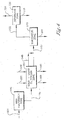
- a process to separate benzoic acid from an oxidizer purge stream 101 is provided as shown in Figure 1 .
- Step (a) comprises subjecting an oxidizer purge stream 101 to evaporation in a first evaporator zone 121 to produce a vapor stream 104 and a concentrated purge slurry 105 .
- the oxidizer purge stream 101 is withdrawn from a carboxylic acid oxidative synthesis process.
- the oxidizer purge stream 101 serves as the feed stream to the present process.
- the oxidizer purge stream 101 comprises at least one carboxylic acid, at least one solvent, at least one metal catalyst and impurities.
- the impurities comprise at least one impurity selected from the group consisting of organic bromides, corrosion metals, p-xylene oxidation by-products, and impurities derived as a result of impurities in the p-xylene.
- the organic bromides may be used as promoters in the oxidation reaction.
- the oxidizer purge stream 101 also contains by-products and impurities. These by-products and impurities arise partially from minor impurities present in the p-xylene feed stream. Other impurities arise due to the incomplete oxidation of p-xylene resulting in partially oxidized products. Still other by-products result from competing side reactions in the oxidation of p-xylene to terephthalic acid.
- the carboxylic acids include any aromatic carboxylic acids produced via controlled oxidation of an organic substrate.
- aromatic carboxylic acids include compounds with at least one carboxylic acid group attached to a carbon atom that is part of an aromatic ring, preferably having at least 6 carbon atoms, even more preferably having only carbon atoms.
- Suitable examples of such aromatic rings include, benzene, biphenyl, terphenyl, naphthalene, and other carbon-based fused aromatic rings.
- suitable carboxylic acids include, terephthalic acid, benzoic acid, p-toluic acid, isophthalic acid, trimellitic acid, naphthalene dicarboxylic acid, 2,5-diphenyl-terephthalic acid, and mixtures thereof.
- Suitable solvents include, aliphatic mono-carboxylic acids, preferably containing 2 to 6 carbon atoms, or benzoic acid and mixtures thereof and mixtures of these compounds with water.
- the solvent is acetic acid mixed with water in a ratio of about 5:1 to about 25:1, preferably between about 8:1 and about 20:1.
- acetic acid will be referred to as the solvent.
- suitable solvents such as those disclosed previously, may also be utilized.
- the oxidizer purge stream 101 is concentrated by conventional means in a first evaporator zone 121 comprising at least one evaporator to produce a vapor stream 104 and a concentrated purge slurry 105 .
- the evaporator is operated at atmospheric or slightly super atmospheric conditions, generally from 1x10 5 Pa (1 atmosphere) to 1x10 6 Pa (10 atmospheres).
- the vapor stream 104 comprises a majority of the water and solvent, and the concentrated purge slurry 105 comprises the remainder of the water and solvent not removed from the oxidizer purge stream 101 .
- majority means greater than 50% by weight.
- the evaporation removes 50 wt%(weight percent) to 80 wt% of the solvent and water, typically acetic acid and water, which are present in the oxidizer purge stream 101.
- Step (a1) comprising subjecting the concentrated purge slurry 105 to evaporation in a second evaporator zone 150 to produce a solvent rich stream 144 and a super concentrated purge slurry 145 .
- the second evaporator zone 150 comprises at least one evaporator operated at vacuum conditions.
- the evaporation can be conducted at a temperature from 20°C to 70°C; another range is from 30°C to 50°C.
- the combination of evaporators 121 and 150 is operated so as to concentrate the oxidizer purge stream as represented by stream 101 to a condition wherein 75 wt% to 99 wt% of the solvent and water, typically acetic acid and water, are removed from the oxidizer purge stream 101 to produce the super concentrated purge slurry 145 .
- another range for operation of the combination of evaporators 121 and 150 is operated so as to concentrate the oxidizer purge stream as represented by stream 101 to a condition wherein 85 wt% to 99 wt% of the solvent and water, typically acetic acid and water, is removed from the oxidizer purge stream 101 to produce the super concentrated purge slurry 145 .
- the first evaporation zone 121 and the second evaporator zone can be combined in a main evaporation zone 125 as shown in Figure 4 .
- the main evaporation zone 125 comprises at least one evaporator.
- the evaporator or evaporators in the main evaporation zone 125 are operated at a temperature and pressure sufficient to remove at least 75% by weight of the solvent and water combined from the oxidizer purge stream 101 .
- the evaporator or evaporators in the main evaporation zone 125 are operated at a temperature and pressure sufficient to remove at least 85% by weight of the solvent and water combined from the oxidizer purge stream.
- the evaporator or evaporators in the main evaporation zone 125 are operated at a temperature and pressure sufficient to remove at least 90% by weight of the solvent and water combined from the oxidizer purge stream 101 . In another embodiment of the invention, the evaporator or evaporators in the main evaporation zone 125 are operated at a temperature and pressure sufficient to remove at least 95% by weight of the solvent and water combined from the oxidizer purge stream.
- Ranges stated in this disclosure and the claims that follow should be understood to disclose the entire range specifically and not just the end point(s). For example, disclosure of the range 0 to 10 should be taken to specifically disclose 2, 2.5, 3.17 and all other number subsumed and not just 0 and 10.
- condition of the super concentrated purge slurry 145 can be as a solid-liquid mixture with only enough solvent to provide pumpability.
- Step (b) comprises filtering the super concentrated purge slurry 145 in a solid-liquid separation zone 151 to form a filter cake 154 and a mother liquor 147 wherein said solid-liquid separation zone comprises at least one device selected from the group consisting of pressure belt filters, filter presses, centrifuges, pressure leaf filters, and cross-flow filters.
- Step (c) comprises washing the filter cake 154 with a wash feed 149 in the solid-liquid separation zone 151 to form a washed cake 146 and a wash filtrate 148 ; wherein the solid-liquid separation zone 151 comprises at least one pressure filtration device.
- the super concentrated purge slurry 145 is introduced in the solid-liquid separation zone 151 where the solid-liquid separation zone comprises a filtration zone 153 , a washing zone 155 , and optionally a drying zone 157 as shown in Figure 2 .
- the filtration zone 153 comprises a filter cell, or a series of filter cells, physically situated to permit a filter cake 154 to develop a distribution across the area of the filter cell to hinder or prevent the channeling of wash feed 149 through the filter cake 154 .
- a filter cake 154 of at least 0.64 cm (0.25 inch) in depth to 20 cm (8 inches) in depth, preferably at least 1.3 cm (0.5 inch) in depth, more preferably at least 3 cm (1 inch) in depth, and even more preferably about 5 to about 10 cm (2 to 4 inches) in depth is distributed over the area of the filter cell.
- the washed cake, 146 can be recovered or further treated, recycled and/or sent to waste treatment facilities.
- the filter cake 154 Upon obtaining a suitable or preferred height of filter cake 154 the filter cake 154 leaves the filtration zone 153 which comprises a filter or series of filters and enters a washing zone 155 where the filter cake 154 is contacted with a wash feed 149 .
- a pressure gradient of at least 3.4 kPa (0.5 psi), preferably from 3x10 4 Pa (5 psi) to 45x10 4 Pa (65 psi), across the filter cake 154 and the reservoir of wash feed 149 can be applied to displace any solute in the filter cake 154 with wash feed 149 .
- a filter cake 154 depth of at least 1.3 cm (0.5 inch) is suitable to obtain a filter cake 154 of sufficient compactness to furnish a wash vehicle, i.e. the filter cake 154 , from which a wash filtrate 148 containing a solute from the filter cake 154 can be removed efficiently by displacement washing. If the filter cake depth 154 is less than 0.64 cm (0.25 inch), channeling of wash feed 149 in the filter cake 154 can occur resulting in non-uniform washing of the filter cake 154 .
- a minimum filter cake 154 depth of at least 0.64 cm (0.25 inch) of purified terephthalic acid is preferred.
- a minimum liquid height above the filter cake 154 surface is required to ensure that displacement washing occurs. This height must be sufficient to ensure that the filter cake 154 surface is completely covered with wash feed 149 . If the filter cake 154 surface is not covered with wash feed 149 , bypassing of the wash feed 149 can occur without adequate displacement of the solute in the filter cake 154 . Because of irregularities in the filter cake 154 surface, a minimum liquid height of 0.64 cm (0.25 inch) is preferred above the filter cake 154 surface.
- Utilization of added stages in the solid-liquid separation zone 151 can decrease the amount of wash feed 149 required to reduce the total amount of metal catalyst retained in the filter cake 154 . It is convenient therefore that a suitable number of stages of positive displacement washing be used to minimize total wash feed 149 used in displacement washing to reduce need for downstream waste treatment facilities.
- multiple stages of the displacement washing procedure can replace a single stage displacement washing procedure wherein the quantity of wash feed 149 is sufficient to obtain at least 80 wt% recovery of the metal catalyst from the super concentrated slurry 145 to the mother liquor 147 and the wash filtrate 148 . Additionally, a procedure utilizing multiple stages of counter-current washing can be useful if reduction of the amount of wash feed 149 is determined to be advantageous.
- a super concentrated purge slurry 145 is introduced into one or more of a series of filter cells physically situated to permit a filter cake 154 of requisite thickness to develop.
- the filter cake 154 leaves the filter or series of filters and enters a washing zone 155 where the filter cake 154 is washed with a wash feed 149 .
- Pressure can then be applied to the wash feed 149 to displace the solute (i.e. the liquid and any dissolved compounds such as metal catalyst in the filter cake) of the filter cake 154 .
- the filter cake 154 can be discharged from the filtration zone 155 by any suitable means, and the cycle repeated.
- the ratio of wash feed 149 to filter cake 154 discharge is within the range of from about 1:20 to about 20:1 to reduce the level of metal catalyst in the filter cake by greater than 95 wt%.
- Equipment for performing the requisite washing cycle can comprise a series of filter cells maintained in a suitable position to permit a wash feed 149 reservoir to develop over the filter cells.
- suitable equipment can comprise a rotary drum pressure filter with multiple filter cells, fitted with a means for discharging washed cake 146 from the filter cells.
- the filter cake 154 can be washed for as many times as required to develop a minimum concentration of metal catalyst in the washed cake 146 before discharging the washed cake 146 from the filter device.
- a suitable pressure filter which can be adapted to the requirements of the instant invented process is a BHS-FEST TM rotary drum pressure filter, BHS-WERK, Sonthofen, D-8972, Sonthofen, West Germany, although other pressure filters which can accomplish the required operation can be used.
- Devices that can be used in the solid-liquid separation zone include 151, are pressure belt filters, filter presses, centrifuges, pressure leaf filters, and cross-flow filters.
- the pressure filter can be operated at a temperature and pressure sufficient to obtain at least 80 wt% recovery of the metal catalyst from the solute of the mother liquor 147 .
- the pressure filter can be operated at a temperature of 25°C to 160 °C, and a pressure of 1 ⁇ 10 5 Pa (1 atmospheres) to 5 ⁇ 10 6 Pa (50 atmospheres).
- a rotary drum In the operation of the BHS-FEST TM filter, a rotary drum contains a series of filter cells located on the periphery of the rotating drum. As the drum rotates, the filter cells receive a super concentrated purge slurry 145 and a filter cake 154 builds to a requisite depth. The mother liquor 147 is produced by filtration of the super concentrated purge slurry 145 .
- the filter cake 154 Upon rotation of the drum, the filter cake 154 enters a washing zone 155 where a reservoir of wash feed 149 is built up over the filter cake 154 to a required depth: The applied pressure to the wash feed reservoir forces the water through the filter cake 154 to displace the solute (with dissolved metal catalyst) retained in the super concentrated purge slurry 145 to produce a washed cake 146 .
- the wash cycle can be repeated at least three more times if necessary in a counter current fashion, after which the system pressure is released with attendant temperature decrease to ambient conditions.
- the washed cake 146 can be dewatered in a dewatering zone 157 with a vapor via conduit 152 to produce a dewatered cake 159 and a humid vapor 160 .
- the resultant dewatered cake 159 can then be discharged from the drum by any conventional means.
- Figure 3 illustrates an embodiment of the invention where a rotary pressure drum filter is utilized as the process filtration device.
- the rotary drum pressure filter comprises a filtration zone 153 , a wash zone 155 , optionally, a dewatering zone 157 , a discharge zone 164 and a cloth wash zone 162 .
- the cloth wash zone shown in Figure 3 is an embodiment of the invention where the rotary pressure drum filter comprises a cloth wash zone 162 where the filters are washed after discharge of the dewatered cake 159 .
- the wash filtrate 148 is produced by displacement washing the filter cake with the wash feed 149 .
- the filter cake 154 within the solid-liquid separation zone 151 undergoes extraction of metal catalyst by introduction of the wash feed 149 to form the wash filtrate 148 .
- at least 80 wt% of the metal catalyst is recovered in the wash filtrate 148 and the mother liquor 147 .
- at least 90 wt% of the metal catalyst is recovered in the wash filtrate 148 and the mother liquor 147 .
- the wash feed 149 comprises water and optionally an additional oxidation solvent.
- Step (d) comprises subjecting the mother liquor 147 to evaporation in an evaporator zone 210 to produce a solvent rich vapor stream 202 and wash filtrate residue 201 .
- the evaporator zone 210 comprises at least one evaporator.
- the evaporator is operated at atmospheric or slightly super atmospheric conditions, generally from about 1 ⁇ 10 5 Pa (1 atmosphere) to about 1 ⁇ 10 6 Pa (10 atmospheres).
- the solvent rich vapor 202 comprises a majority of the water and solvent
- the wash filtrate residue 201 comprises the remainder of the water and solvent not removed from the mother liquor 147 and the majority of the catalyst.
- the evaporation removes 90 wt% to 99 wt% of the solvent and water from the combined stream in conduit 147 , typically acetic acid and water, which are present in the wash filtrate 148 and the majority of the benzoic acid in the mother liquor 147 .
- "Majority" as used herein means greater than 50% by weight.
- Step (e) comprises subjecting the solvent rich vapor stream 202 to conventional distillation in distillation zone 220 to form a benzoic acid rich stream 203 and a solvent rich stream 204 .
- the separation zone 220 comprises at least one liquid-vapor separator.
- the separator operates at atmospheric or slightly super atmospheric conditions, generally from 1 ⁇ 10 5 Pa (1 atmosphere) to 1 ⁇ 10 6 Pa (10 atmospheres).
- the liquid-vapor separator comprises at least one theoretical vapor-liquid equilibrium stage. Examples of liquid-vapor separators include, flash condensers and distillation columns.
- the benzoic rich acid stream 203 has greater than 5 wt% benzoic acid. In another embodiment of the invention, the benzoic acid rich stream 203 has greater than 15 wt% benzoic acid. In another embodiment of the invention, the benzoic acid rich stream 203 has greater than 30 wt% benzoic acid. In another embodiment of the invention, the benzoic acid rich stream 203 has greater than 50 wt% benzoic acid. In another embodiment of the invention, the benzoic acid rich stream 203 comprises from about 5 wt% to 75 wt% benzoic acid. In another embodiment of the invention, the benzoic acid rich stream 203 comprises from about 5 wt% to 50 wt% benzoic acid.
- the benzoic acid rich stream 203 comprises from about 5 wt% to 35 wt% benzoic acid. In another embodiment of the invention, the benzoic acid rich stream 203 comprises from about 15 wt% to 30 wt% benzoic acid.
- Step (f) comprises optionally recycling at least a portion of the solvent rich stream 204 back to an oxidation reactor in an aromatic oxidation process.
- At least a portion of the solvent rich stream can be recycled back to an oxidation reactor in the oxidation process.
- "At least a portion” can mean at least 5 wt%, at least 15 wt%, at least 30 wt%, at least 50 wt%, at least 75 wt%, or all of the solvent rich stream is recycled 204 back to an oxidation reactor.
- composition of the various streams in the process varies depending on the process conditions, a typical composition of the streams, using a computer simulated model(ASPEN version 12.1) of the process, are shown in Tables 1a and 1 b.
- Tables 1a and 1b the components are shown in the left hand column, and the amount of these components in each stream in Figure 1 are shown in the number column corresponding to the number of the stream in Figure 1 .
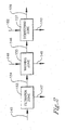
- FIG. 5 a process is provided as shown in Figure 5 , which is not according to the invention.
- Table 1A ASPEN SIMULATION OF PROCESS 101 MASS% 104 MASS% 105 MASS% 144 MASS% 145 MASS% 146 MASS% 147 MASS% WATER 7.7 8.9 4.3 6.0 2.7 20.0 3.5 ACETIC ACID 88.4 91.1 80.2 94.0 66.7 0.0 86.6 TEREPHTHALIC ACID 2.9 0.0 11.4 0.0 22.7 74.0 2.3 OTHER ORGANICS 0.6 0.1 2.0 0.0 4.0 5.9 3.1 BENZOIC ACID 0.3 0.0 1.1 0.0 2.1 0.0 2.8 METALS AND BROMINE COMPLEX 0.2 0.0 0.9 0.0 1.8 0.1 1.7 TOTAL FLOW kg/hr 10000 7500 2500 1241 1259 351 894 TEMPERATURE C 121.2 123.5 123.5 49.4 49.4 83.0 49.4 Table 1B 148 MASS% 149 MASS%
Description
- This invention relates to the removal of impurities, specifically benzoic acid, from a mother liquor produced in the synthesis of carboxylic acid, typically terephthalic acid. This invention also relates to the removal of impurities, specifically benzoic acid, from a benzoic acid bearing stream produced in the synthesis of carboxylic acid.
- Terephthalic acid is commercially produced by oxidation of paraxylene in the presence of a catalyst, such as, for example, Co, Mn, Br and a solvent. Terephthalic acid used in the production of polyester fibers, films, and resins must be further treated to remove impurities formed as a result of the oxidation of paraxylene.
- Terephthalic acid (TPA) is an intermediate in the production of polyesters for plastics and fiber applications. Commercial processes for the manufacture of TPA are often based on the heavy-metal catalyzed oxidation of p-xylene, generally with a bromide promoter in an acetic acid solvent. Due to the limited solubility of TPA in acetic acid under practical oxidation conditions, a slurry of TPA crystals is usually formed in the oxidation reactor. Typically, the TPA oxidizer slurry is withdrawn from the reactor, and TPA solids are separated from the oxidizer mother liquor using conventional solid-liquid separation techniques. The oxidizer mother liquor, which contains most of the catalyst and promoter used in the process, is recycled to the oxidation reactor. Aside from the catalyst and promoter, the oxidizer mother liquor stream also contains dissolved TPA and many by-products and impurities. These by-products and impurities arise partially from minor impurities present in the p-xylene feed stream. Other impurities arise due to the incomplete oxidation of p-xylene resulting in partially oxidized products. Still other by-products result from competing side reactions formed as a result of the oxidation of p-xylene to terephthalic acid.
- The TPA solids undergo a solid-liquid separation wherein fresh solvent is utilitized to displace a major portion of the liquid component of the oxidizer mother liquor. After drying, the TPA solids are contaminated with impurities that were present in the oxidizer mother liquor since these impurities may be incorporated into the TPA solids. Impurities are also present due to occlusions in the TPA crystal structure and due to incomplete removal of the oxidizer mother liquor by the fresh solvent wash.
- Many of the impurities in the oxidizer mother liquor stream that are recycled are relatively inert to further oxidation. Such impurities include, for example, isophthalic acid, phthalic acid and trimellitic acid. Impurities, which may undergo further oxidation are also present, such as, for example, 4-carboxybenzaldehyde, p-toluic acid and p-tolualdehyde. Oxidation inert impurities tend to accumulate in the oxidizer mother liquor upon recycle. The concentration of these inert impurities will increase in the oxidizer mother liquor until an equilibria is reached whereby the rate of removal of each impurity via the TPA product balances with the rate of formation and the rate of addition to the oxidation process. The normal level of impurities in commercial crude TPA makes it unsuitable for direct use in most polymer applications.
- Conventionally, crude TPA has been purified either by conversion of a dimethyl ester or by dissolution in water with subsequent hydrogenation over standard hydrogenation catalysts. More recently, secondary oxidative treatments have been used to produce polymer-grade TPA. It is desirable to minimize the concentration of impurities in the mother liquor and thereby facilitate subsequent purification of TPA. In some cases, it is not possible to produce a purified, polymer-grade TPA unless some means for removing impurities from the oxidizer mother liquor stream are utilized.
-
WO 9730963 (A1 -
GB 2067563 (A - One technique for impurity removal from a recycle stream commonly used in the chemical processing industry is to draw out or "purge" some portion of the recycle stream. Typically, the purge stream is simply disposed of or, if economically justified, subjected to various treatments to remove undesired impurities while recovering valuable components. One example of this process is
U.S. # 4,939,297 . The amount of purge required for control of impurities is process-dependent; however, a purge amount equal to 10-40 wt% of the total oxidizer mother liquor stream is usually sufficient to produce TPA adequate as feedstock for commercial polymer manufacture. In the production of TPA, the percentage of the oxidizer mother liquor stream purge necessary to maintain acceptable impurity concentrations, coupled with the economic value of the metal catalyst and solvent components in the oxidizer purge stream, make simple disposal of the oxidizer purge stream economically unattractive. Thus, there is a need for a process that recovers essentially all of the valuable metal catalysts and acetic acid contained in the oxidizer purge stream while removing a major portion of the impurities present in the oxidizer purge stream. The metal catalyst can be recovered in an active form suitable for reuse by direct recycling to the p-xylene oxidation step. - One benefit of this invention is the energy and capital cost savings compared with the extraction based purge process previously described.
- Another benefit of this invention is its efficacy compared with extraction purge processes regarding the usefulness of the solvent stream(s) recycled to the TPA process. The primary motivation in a liquid extraction process is based upon the assumption that introducing any aromatic impurities into a p-xylene oxidation process for producing terephthalic acid has a detrimental effect on the terephthalic acid powder quality (e.g. yellow color). Hence, it was assumed that a broad spectrum removal of aromatic impurities, such as provided by liquid extraction, was necessary to achieve appropriate terephthalic acid powder quality.
- In one embodiment of this invention, however, employs a relatively simple process that separates benzoic acid from an aqueous solvent. The efficiency of the process toward benzoic acid is high since benzoic acid is more volatile (a higher vapor pressure) than most identified aromatic impurities in the production of a carboxylic acid, typically terephthalic acid. These aromatic impurities include, trimellitic acid, isophthalic acid, stilbenes, and anthraquinones. Therefore, it is rather surprising that removal of a benzoic acid in favor of the other known impurities, that are inherently colored, would be sufficient to produce a carboxylic acid, typically terephthalic acid of good quality.
- In a first embodiment of this invention, a process to produce a benzoic acid stream is provided. The process comprises:
- (a) subjecting an oxidizer purge stream to evaporation in a main evaporator zone to produce a vapor stream and a super concentrated purge slurry;
- (b) filtering the super concentrated purge slurry in a solid-liquid separation zone to form a filter cake and a mother liquor wherein said solid-liquid separation zone comprises at least one device selected from the group consisting of pressure belt filters, filter presses, centrifuges, pressure leaf filters, and cross-flow filters;
- (c) washing the filter cake with a wash feed in said solid-liquid separation zone to form a washed cake and a wash filtrate;
- (d) subjecting the mother liquor to evaporation in a evaporator zone to form a solvent rich vapor; and
- (e) subjecting the solvent rich vapor to distillation in a separation zone to form a solvent rich stream and a benzoic acid rich stream.
- In another embodiment of this invention, a process to produce a benzoic acid stream is provided.
- The process comprises:
- (a1) subjecting an oxidizer purge stream to evaporation in a first evaporator zone to produce a vapor stream and a concentrated purge slurry;
- (a2) subjecting the concentrated purge slurry to evaporation in a second evaporator zone to form a solvent rich stream and a super concentrated purge slurry;
- (b) filtering a super concentrated purge slurry in a solid-liquid separation zone to form a filter cake and a mother liquor wherein said solid-liquid separation zone comprises at least one device selected from the group consisting of pressure belt filters, filter presses, centrifuges, pressure leaf filters, and cross-flow filters;
- (c) washing the filter cake with a wash feed in the solid-liquid separation zone to form a washed cake and a wash filtrate; wherein the solid- liquid separation zone comprises at least one pressure filtration device;
- (d) subjecting the mother liquor to evaporation in a evaporator zone to from a solvent rich vapor; and
- (e) subjecting the solvent rich vapor to distillation in a separation zone to form a solvent rich stream and a benzoic acid rich stream; wherein the benzoic acid rich stream comprises at least 60% by weight benzoic acid.
-
-
Figure 1 illustrates different embodiments of the invention wherein a process to recover benzoic acid from anoxidizer purge stream 101 is shown. -
Figure 2 illustrates an embodiment of the process occurring in the solid-liquid separation zone 151 wherein the solid-liquid separation zone comprises afiltration zone 153, awashing zone 155, and optionally adewatering zone 157. -
Figure 3 illustrates an embodiment of the invention where a rotary pressure drum filter is utilized in the solid-liquid separation zone. -
Figure 4 illustrates an embodiment of the invention wherein a process to recover benzoic acid from anoxidizer purge stream 101 is shown, and the process utilizes amain evaporator zone 125. -
Figure 5 illustrates an embodiment not according to the invention wherein a process to recovery benzoic acid from a benzoicacid bearing stream 347 is provided. - In one embodiment of this invention, a process to separate benzoic acid from an
oxidizer purge stream 101 is provided as shown inFigure 1 . - Step (a) comprises subjecting an
oxidizer purge stream 101 to evaporation in a first evaporator zone 121 to produce avapor stream 104 and aconcentrated purge slurry 105. - In an embodiment of the invention, the
oxidizer purge stream 101 is withdrawn from a carboxylic acid oxidative synthesis process. Theoxidizer purge stream 101 serves as the feed stream to the present process. In an embodiment of the invention, theoxidizer purge stream 101 comprises at least one carboxylic acid, at least one solvent, at least one metal catalyst and impurities. The impurities comprise at least one impurity selected from the group consisting of organic bromides, corrosion metals, p-xylene oxidation by-products, and impurities derived as a result of impurities in the p-xylene. The organic bromides may be used as promoters in the oxidation reaction. Examples of corrosion metals are iron and chromium compounds, which inhibit, reduce or entirely destroy the activity of the metal catalyst. Aside from the catalyst and promoter, theoxidizer purge stream 101 also contains by-products and impurities. These by-products and impurities arise partially from minor impurities present in the p-xylene feed stream. Other impurities arise due to the incomplete oxidation of p-xylene resulting in partially oxidized products. Still other by-products result from competing side reactions in the oxidation of p-xylene to terephthalic acid. - The carboxylic acids include any aromatic carboxylic acids produced via controlled oxidation of an organic substrate. Such aromatic carboxylic acids include compounds with at least one carboxylic acid group attached to a carbon atom that is part of an aromatic ring, preferably having at least 6 carbon atoms, even more preferably having only carbon atoms. Suitable examples of such aromatic rings include, benzene, biphenyl, terphenyl, naphthalene, and other carbon-based fused aromatic rings. Examples of suitable carboxylic acids include, terephthalic acid, benzoic acid, p-toluic acid, isophthalic acid, trimellitic acid, naphthalene dicarboxylic acid, 2,5-diphenyl-terephthalic acid, and mixtures thereof.
- Suitable solvents include, aliphatic mono-carboxylic acids, preferably containing 2 to 6 carbon atoms, or benzoic acid and mixtures thereof and mixtures of these compounds with water. Preferably, the solvent is acetic acid mixed with water in a ratio of about 5:1 to about 25:1, preferably between about 8:1 and about 20:1. Throughout the specification, acetic acid will be referred to as the solvent. However, it should be appreciated that other suitable solvents, such as those disclosed previously, may also be utilized.
- In the first step of the present process, the
oxidizer purge stream 101 is concentrated by conventional means in a first evaporator zone 121 comprising at least one evaporator to produce avapor stream 104 and aconcentrated purge slurry 105. In an embodiment to the invention, the evaporator is operated at atmospheric or slightly super atmospheric conditions, generally from 1x10⁵ Pa (1 atmosphere) to 1x10⁶ Pa (10 atmospheres). Thevapor stream 104 comprises a majority of the water and solvent, and theconcentrated purge slurry 105 comprises the remainder of the water and solvent not removed from theoxidizer purge stream 101. As used herein "majority" means greater than 50% by weight. In an embodiment of the invention, the evaporation removes 50 wt%(weight percent) to 80 wt% of the solvent and water, typically acetic acid and water, which are present in theoxidizer purge stream 101. - Step (a1) comprising subjecting the
concentrated purge slurry 105 to evaporation in asecond evaporator zone 150 to produce a solventrich stream 144 and a superconcentrated purge slurry 145. - In an embodiment of the invention, the
second evaporator zone 150 comprises at least one evaporator operated at vacuum conditions. In an embodiment of the invention, the evaporation can be conducted at a temperature from 20°C to 70°C; another range is from 30°C to 50°C. In an embodiment of the invention, the combination ofevaporators 121 and 150 is operated so as to concentrate the oxidizer purge stream as represented bystream 101 to a condition wherein 75 wt% to 99 wt% of the solvent and water, typically acetic acid and water, are removed from theoxidizer purge stream 101 to produce the superconcentrated purge slurry 145. In another embodiment of the invention another range for operation of the combination ofevaporators 121 and 150 is operated so as to concentrate the oxidizer purge stream as represented bystream 101 to a condition wherein 85 wt% to 99 wt% of the solvent and water, typically acetic acid and water, is removed from theoxidizer purge stream 101 to produce the superconcentrated purge slurry 145. - In another embodiment of the invention, the first evaporation zone 121 and the second evaporator zone can be combined in a
main evaporation zone 125 as shown inFigure 4 . Themain evaporation zone 125 comprises at least one evaporator. The evaporator or evaporators in themain evaporation zone 125 are operated at a temperature and pressure sufficient to remove at least 75% by weight of the solvent and water combined from theoxidizer purge stream 101. In another embodiment of the invention, the evaporator or evaporators in themain evaporation zone 125 are operated at a temperature and pressure sufficient to remove at least 85% by weight of the solvent and water combined from the oxidizer purge stream. In another embodiment of the invention, the evaporator or evaporators in themain evaporation zone 125 are operated at a temperature and pressure sufficient to remove at least 90% by weight of the solvent and water combined from theoxidizer purge stream 101. In another embodiment of the invention, the evaporator or evaporators in themain evaporation zone 125 are operated at a temperature and pressure sufficient to remove at least 95% by weight of the solvent and water combined from the oxidizer purge stream. - Ranges stated in this disclosure and the claims that follow should be understood to disclose the entire range specifically and not just the end point(s). For example, disclosure of the range 0 to 10 should be taken to specifically disclose 2, 2.5, 3.17 and all other number subsumed and not just 0 and 10.
- In an embodiment of the invention, the condition of the super
concentrated purge slurry 145 can be as a solid-liquid mixture with only enough solvent to provide pumpability. - Step (b) comprises filtering the super
concentrated purge slurry 145 in a solid-liquid separation zone 151 to form afilter cake 154 and amother liquor 147 wherein said solid-liquid separation zone comprises at least one device selected from the group consisting of pressure belt filters, filter presses, centrifuges, pressure leaf filters, and cross-flow filters. - Step (c) comprises washing the
filter cake 154 with awash feed 149 in the solid-liquid separation zone 151 to form a washedcake 146 and awash filtrate 148; wherein the solid-liquid separation zone 151 comprises at least one pressure filtration device. - In an embodiment of the invention, the super
concentrated purge slurry 145 is introduced in the solid-liquid separation zone 151 where the solid-liquid separation zone comprises afiltration zone 153, awashing zone 155, and optionally adrying zone 157 as shown inFigure 2 . Thefiltration zone 153 comprises a filter cell, or a series of filter cells, physically situated to permit afilter cake 154 to develop a distribution across the area of the filter cell to hinder or prevent the channeling of wash feed 149 through thefilter cake 154. - Suitably, a
filter cake 154 of at least 0.64 cm (0.25 inch) in depth to 20 cm (8 inches) in depth, preferably at least 1.3 cm (0.5 inch) in depth, more preferably at least 3 cm (1 inch) in depth, and even more preferably about 5 to about 10 cm (2 to 4 inches) in depth is distributed over the area of the filter cell. The washed cake, 146, can be recovered or further treated, recycled and/or sent to waste treatment facilities. - Upon obtaining a suitable or preferred height of
filter cake 154 thefilter cake 154 leaves thefiltration zone 153 which comprises a filter or series of filters and enters awashing zone 155 where thefilter cake 154 is contacted with awash feed 149. In one embodiment of the invention, there is sufficient pressure across thefilter cake 154 to allow a reservoir or buildup of the wash feed 149 over thefilter cake 154 to a suitable depth, preferably to a minimum depth of 0.64 cm (0.25 inch). A pressure gradient of at least 3.4 kPa (0.5 psi), preferably from 3x10⁴ Pa (5 psi) to 45x104 Pa (65 psi), across thefilter cake 154 and the reservoir of wash feed 149 can be applied to displace any solute in thefilter cake 154 withwash feed 149. - A
filter cake 154 depth of at least 1.3 cm (0.5 inch) is suitable to obtain afilter cake 154 of sufficient compactness to furnish a wash vehicle, i.e. thefilter cake 154, from which awash filtrate 148 containing a solute from thefilter cake 154 can be removed efficiently by displacement washing. If thefilter cake depth 154 is less than 0.64 cm (0.25 inch), channeling of wash feed 149 in thefilter cake 154 can occur resulting in non-uniform washing of thefilter cake 154. - Because of the loss of efficiency in displacement washing of the
filter cake 154, aminimum filter cake 154 depth of at least 0.64 cm (0.25 inch) of purified terephthalic acid is preferred. - A minimum liquid height above the
filter cake 154 surface is required to ensure that displacement washing occurs. This height must be sufficient to ensure that thefilter cake 154 surface is completely covered withwash feed 149. If thefilter cake 154 surface is not covered withwash feed 149, bypassing of the wash feed 149 can occur without adequate displacement of the solute in thefilter cake 154. Because of irregularities in thefilter cake 154 surface, a minimum liquid height of 0.64 cm (0.25 inch) is preferred above thefilter cake 154 surface. - It has been found that displacement of the solute from the
filter cake 154 using the wash feed 149 at high pressure permits an efficient separation of catalyst metals from thefilter cake 154. Another benefit of high pressure is the reduction of wash feed 149 required to recover cobalt as shown in the examples. - Utilization of added stages in the solid-
liquid separation zone 151 can decrease the amount of wash feed 149 required to reduce the total amount of metal catalyst retained in thefilter cake 154. It is convenient therefore that a suitable number of stages of positive displacement washing be used to minimize total wash feed 149 used in displacement washing to reduce need for downstream waste treatment facilities. - It is understood that multiple stages of the displacement washing procedure can replace a single stage displacement washing procedure wherein the quantity of
wash feed 149 is sufficient to obtain at least 80 wt% recovery of the metal catalyst from the superconcentrated slurry 145 to themother liquor 147 and thewash filtrate 148. Additionally, a procedure utilizing multiple stages of counter-current washing can be useful if reduction of the amount ofwash feed 149 is determined to be advantageous. - In the process of the instant invention, a super
concentrated purge slurry 145 is introduced into one or more of a series of filter cells physically situated to permit afilter cake 154 of requisite thickness to develop.
Upon obtaining a minimum height offilter cake 154, about 0.64 cm to about 10 cm (0.25 to 4 inches), thefilter cake 154 leaves the filter or series of filters and enters awashing zone 155 where thefilter cake 154 is washed with awash feed 149. Pressure can then be applied to the wash feed 149 to displace the solute (i.e. the liquid and any dissolved compounds such as metal catalyst in the filter cake) of thefilter cake 154. Upon displacement of the solute with the wash feed, thefilter cake 154 can be discharged from thefiltration zone 155 by any suitable means, and the cycle repeated. In an embodiment of the invention, the ratio of wash feed 149 to filtercake 154 discharge is within the range of from about 1:20 to about 20:1 to reduce the level of metal catalyst in the filter cake by greater than 95 wt%. - Equipment for performing the requisite washing cycle can comprise a series of filter cells maintained in a suitable position to permit a
wash feed 149 reservoir to develop over the filter cells. In one embodiment of the invention, suitable equipment can comprise a rotary drum pressure filter with multiple filter cells, fitted with a means for discharging washedcake 146 from the filter cells. Thefilter cake 154 can be washed for as many times as required to develop a minimum concentration of metal catalyst in the washedcake 146 before discharging the washedcake 146 from the filter device. - A suitable pressure filter which can be adapted to the requirements of the instant invented process is a BHS-FEST™ rotary drum pressure filter, BHS-WERK, Sonthofen, D-8972, Sonthofen, West Germany, although other pressure filters which can accomplish the required operation can be used. Devices that can be used in the solid-liquid separation zone include 151, are pressure belt filters, filter presses, centrifuges, pressure leaf filters, and cross-flow filters. The pressure filter can be operated at a temperature and pressure sufficient to obtain at least 80 wt% recovery of the metal catalyst from the solute of the
mother liquor 147. Preferably, the pressure filter can be operated at a temperature of 25°C to 160 °C, and a pressure of 1 × 10⁵ Pa (1 atmospheres) to 5 × 10⁶ Pa (50 atmospheres). - In the operation of the BHS-FEST™ filter, a rotary drum contains a series of filter cells located on the periphery of the rotating drum. As the drum rotates, the filter cells receive a super
concentrated purge slurry 145 and afilter cake 154 builds to a requisite depth. Themother liquor 147 is produced by filtration of the superconcentrated purge slurry 145. Upon rotation of the drum, thefilter cake 154 enters awashing zone 155 where a reservoir ofwash feed 149 is built up over thefilter cake 154 to a required depth: The applied pressure to the wash feed reservoir forces the water through thefilter cake 154 to displace the solute (with dissolved metal catalyst) retained in the superconcentrated purge slurry 145 to produce a washedcake 146. Upon further rotation of the drum, the wash cycle can be repeated at least three more times if necessary in a counter current fashion, after which the system pressure is released with attendant temperature decrease to ambient conditions. Optionally, the washedcake 146 can be dewatered in adewatering zone 157 with a vapor viaconduit 152 to produce a dewateredcake 159 and ahumid vapor 160. The resultant dewateredcake 159 can then be discharged from the drum by any conventional means. -
Figure 3 illustrates an embodiment of the invention where a rotary pressure drum filter is utilized as the process filtration device. In an embodiment of the invention, the rotary drum pressure filter comprises afiltration zone 153, awash zone 155, optionally, adewatering zone 157, adischarge zone 164 and acloth wash zone 162. The cloth wash zone shown inFigure 3 is an embodiment of the invention where the rotary pressure drum filter comprises acloth wash zone 162 where the filters are washed after discharge of the dewateredcake 159. - The
wash filtrate 148 is produced by displacement washing the filter cake with thewash feed 149. Thefilter cake 154 within the solid-liquid separation zone 151 undergoes extraction of metal catalyst by introduction of the wash feed 149 to form thewash filtrate 148. In an embodiment of the invention, at least 80 wt% of the metal catalyst is recovered in thewash filtrate 148 and themother liquor 147. In an embodiment of the invention, at least 90 wt% of the metal catalyst is recovered in thewash filtrate 148 and themother liquor 147. The wash feed 149 comprises water and optionally an additional oxidation solvent. - Perhaps most surprisingly by utilizing water as a
wash feed 149 at temperatures in the range of 20°C to 70°C, preferably 30°C to 50°C, sufficient corrosion metal is retained in the dewateredcake 159 wherein the need for corrosion metal removal by other means is eliminated. The dewateredcake 159 which represents solids stripped of metal catalyst can be disposed from the system. - Step (d) comprises subjecting the
mother liquor 147 to evaporation in anevaporator zone 210 to produce a solventrich vapor stream 202 and washfiltrate residue 201. - The
evaporator zone 210 comprises at least one evaporator. In an embodiment of the invention, the evaporator is operated at atmospheric or slightly super atmospheric conditions, generally from about 1 × 10⁵ Pa (1 atmosphere) to about 1 × 10⁶ Pa (10 atmospheres). The solventrich vapor 202 comprises a majority of the water and solvent, and thewash filtrate residue 201 comprises the remainder of the water and solvent not removed from themother liquor 147 and the majority of the catalyst. The evaporation removes 90 wt% to 99 wt% of the solvent and water from the combined stream inconduit 147, typically acetic acid and water, which are present in thewash filtrate 148 and the majority of the benzoic acid in themother liquor 147. "Majority" as used herein means greater than 50% by weight. - Step (e) comprises subjecting the solvent
rich vapor stream 202 to conventional distillation indistillation zone 220 to form a benzoic acidrich stream 203 and a solventrich stream 204. - The
separation zone 220 comprises at least one liquid-vapor separator. In an embodiment of the invention, the separator operates at atmospheric or slightly super atmospheric conditions, generally from 1 × 10⁵ Pa (1 atmosphere) to 1 × 10⁶ Pa (10 atmospheres). The liquid-vapor separator comprises at least one theoretical vapor-liquid equilibrium stage. Examples of liquid-vapor separators include, flash condensers and distillation columns. - In an embodiment of the invention, the benzoic
rich acid stream 203 has greater than 5 wt% benzoic acid. In another embodiment of the invention, the benzoic acidrich stream 203 has greater than 15 wt% benzoic acid. In another embodiment of the invention, the benzoic acidrich stream 203 has greater than 30 wt% benzoic acid. In another embodiment of the invention, the benzoic acidrich stream 203 has greater than 50 wt% benzoic acid. In another embodiment of the invention, the benzoic acidrich stream 203 comprises from about 5 wt% to 75 wt% benzoic acid. In another embodiment of the invention, the benzoic acidrich stream 203 comprises from about 5 wt% to 50 wt% benzoic acid. In another embodiment of the invention, the benzoic acidrich stream 203 comprises from about 5 wt% to 35 wt% benzoic acid. In another embodiment of the invention, the benzoic acidrich stream 203 comprises from about 15 wt% to 30 wt% benzoic acid. - Step (f) comprises optionally recycling at least a portion of the solvent
rich stream 204 back to an oxidation reactor in an aromatic oxidation process. - At least a portion of the solvent rich stream can be recycled back to an oxidation reactor in the oxidation process. "At least a portion" can mean at least 5 wt%, at least 15 wt%, at least 30 wt%, at least 50 wt%, at least 75 wt%, or all of the solvent rich stream is recycled 204 back to an oxidation reactor.
- An example of an aromatic oxidation process is disclosed
US. Patent Application 10/156,312 - Although the composition of the various streams in the process varies depending on the process conditions, a typical composition of the streams, using a computer simulated model(ASPEN version 12.1) of the process, are shown in Tables 1a and 1 b. In Tables 1a and 1b, the components are shown in the left hand column, and the amount of these components in each stream in
Figure 1 are shown in the number column corresponding to the number of the stream inFigure 1 . - In another embodiment, a process is provided as shown in
Figure 5 , which is not according to the invention.Table 1A ASPEN SIMULATION OF PROCESS 101 MASS% 104 MASS% 105 MASS% 144 MASS% 145 MASS% 146 MASS% 147 MASS% WATER 7.7 8.9 4.3 6.0 2.7 20.0 3.5 ACETIC ACID 88.4 91.1 80.2 94.0 66.7 0.0 86.6 TEREPHTHALIC ACID 2.9 0.0 11.4 0.0 22.7 74.0 2.3 OTHER ORGANICS 0.6 0.1 2.0 0.0 4.0 5.9 3.1 BENZOIC ACID 0.3 0.0 1.1 0.0 2.1 0.0 2.8 METALS AND BROMINE COMPLEX 0.2 0.0 0.9 0.0 1.8 0.1 1.7 TOTAL FLOW kg/hr 10000 7500 2500 1241 1259 351 894 TEMPERATURE C 121.2 123.5 123.5 49.4 49.4 83.0 49.4 Table 1B 148 MASS% 149 MASS% 201 MASS% 202 MASS% 203 MASS% 204 MASS% WATER 89.8 100.0 0.0 3.7 1.2 3.9 ACETIC ACID 8.1 0.0 1.7 91.7 47.0 94.4 TEREPHTHALIC ACID 0.7 0.0 40.2 0.0 0.0 0.0 OTHER ORGANICS 0.3 0.0 27.1 1.6 20.3 0.5 BENZOIC ACID 0.3 0.0 0.7 2.9 31.5 1.2 METALS AND BROMINE COMPLEX 0.9 0.0 30.2 0.0 0.1 0.0 TOTAL FLOW kg/hr 801 787 51 843 48 795 TEMPERATURE C 60.0 70.9 272.1 272.1 159.5 159.5
Claims (43)
- A process to produce a benzoic acid rich stream, said process comprising:(a) subjecting an oxidizer purge stream to evaporation in a main evaporator zone to produce a vapor stream and a super concentrated purge slurry;(b) filtering said super concentrated purge slurry in a solid-liquid separation zone to form a filter cake and a mother liquor wherein said solid-liquid separation zone comprises at least one device selected from the group consisting of pressure belt filters, filter presses, centrifuges, pressure leaf filters, and cross-flow filters;(c) washing said filter cake with a wash feed in said solid-liquid separation zone to form a washed cake and a wash filtrate;(d) subjecting said mother liquor to evaporation in an evaporator zone to form a solvent rich vapor; and(e) subjecting said solvent rich vapor to distillation in a separation zone to form a solvent rich stream and said benzoic acid rich stream.
- The process according to claim 1 wherein 50 wt% to 80 wt% of said solvent and water is removed from said oxidizer purge stream in step (a).
- The process according to claim 1 wherein 75 wt% to 99 wt% of said solvent and water is removed from said oxidizer purge stream in step (a).
- The process according to claim 1 wherein 85 wt% to 99 wt% of said solvent and water is removed from said oxidizer purge stream in step (a).
- The process according to claims 1, 2, 3, or 4 wherein said wash feed is added to said solid-liquid separation zone at a temperature range of 20°C to 100°C.
- The process according to claim 5 wherein said wash feed is added to said solid-liquid separation zone at a temperature range of 30°C to 50°C.
- The process according to claim 1 wherein said benzoic acid rich stream comprises benzoic acid in an amount greater than 30% by weight.
- The process according to claim 1 wherein said main evaporator zone comprises at least one evaporator operated at a temperature of 20°C to 70°C.
- The process according to claim 1 wherein said solid-liquid separation zone comprises at least one pressure filtration device.
- The process according to claim 9 wherein said pressure filtration device operates at a temperature between 25°C to 160°C.
- The process according to claim 9 wherein said pressure filtration device is operated at a pressure of 1x10⁵ Pa (1 atmosphere) to 5x10⁶ Pa (50 atmospheres).
- The process according to claim 10 or 11 wherein said pressure filtration device comprises at least one filter cell and wherein at least one filter cell accumulates at least 0.64 cm (0.25 inch) in depth of said filter cake.
- The process according to claim 10 or 11 wherein said pressure filtration device comprises at least one filter cell and wherein at least one filter cell accumulates at least 1.3 cm (0.5 inch) in depth of said filter cake.
- The process according to claim 10 or 11 wherein said pressure filtration device comprises at least one filter cell and wherein at least one filter cell accumulates at least 3 cm (1 inch) in depth of said filter cake.
- The process according to claim 10 or 11 wherein said wash feed forms a reservoir over said filter cake which is at least 0.64 cm (0.25 inch) in depth.
- The process according to claim 10 or 11 wherein said pressure filtration device operates at a temperature between 25°C to 160°C
- The process according to claim 16 wherein said pressure filtration device is operated at a pressure of 1x10⁵ Pa (1 atmosphere) to 5x10⁶ Pa (50 atmospheres).
- The process according to claim 17 wherein said drying results in said dewatered cake having a moisture content from 10 wt% to 50 wt%.
- The process according to claim 10 or 11 wherein said pressure filtration device is a rotary pressure drum filter.
- The process according to claim 19 wherein said rotary pressure drum filter is operated at a pressure of 1x10⁵ Pa (1 atmosphere) to 5x10⁵ Pa (5 atmospheres).
- The process according to claim 1 wherein said washing is counter current.
- The process of claim 1, wherein step (a) comprises:(a1) subjecting the oxidizer purge stream to evaporation in a first evaporator zone to produce a vapor stream and a concentrated purge slurry; and(a2) subjecting said concentrated purge slurry to evaporation in a second evaporator zone to form a solvent rich stream and the super concentrated purge slurry.
- The process according to claim 22 wherein 50 wt% to 80 wt% of said solvent and water is removed from said oxidizer purge stream in step (a).
- The process according to claim 22 wherein 75 wt% to 99 wt% of said solvent and water is removed from said oxidizer purge stream in step (a) and step (b) combined.
- The process according to claim 22 wherein 85 wt% to 99 wt% of said solvent and water is removed from said oxidizer purge stream in step (a) and step (b) combined.
- The process according to claim 22 wherein 90 wt% to 99 wt% of said solvent and water is removed from said oxidizer purge stream in step (a) and step (b) combined.
- The process according to claims 22, 23, 24, or 25 wherein said wash feed is added to said solid-liquid separation zone at a temperature range of 20°C to 100°C.
- The process according to claim 22 wherein said wash feed is added to said solid-liquid separation zone at a temperature range of 30°C to 50°C.
- The process according to claim 22 wherein said benzoic acid rich stream comprises benzoic acid in an amount greater than 30% by weight.
- The process according to claim 22 wherein said second evaporator zone comprises an evaporator operated at a temperature of 20°C to 70°C.
- The process according to claim 22 wherein said second evaporator zone comprises at least one evaporator that is operated at vacuum conditions.
- The process according to claim 30 wherein said second evaporator zone comprises an evaporator that is operated at vacuum conditions.
- The process according to claim 22 wherein said at least one device is a pressure filtration device and said pressure filtration device operates at a temperature between 25°C to 160°C.
- The process according to claim 22 wherein said at least one device is a pressure filtration device and said pressure filtration device is operated at a pressure of 1x10⁵ Pa (1 atmosphere) to 5x10⁶ Pa (50 atmospheres).
- The process according to claim 33 or 34 wherein said pressure filtration device comprises at least one filter cell and wherein at least one filter cell accumulates at least 0.64 cm (0.25 inch) in depth of said filter cake.
- The process according to claim 33 or 34 wherein said pressure filtration device comprises at least one filter cell and wherein at least one filter cell accumulates at least 1.3 cm (0.5 inch) in depth of said filter cake.
- The process according to claim 33 or 34 wherein said pressure filtration device comprises at least one filter cell and wherein at least one filter cell accumulates at least 3 cm (1 inch) in depth of said filter cake.
- The process according to claim 33 or 34 wherein said wash feed forms a reservoir over said filter cake which is at least 0.64 cm (0.25 inch) in depth.
- The process according to claim 33 or 34 wherein said pressure filtration device operates at a temperature between 25°C to 160°C.
- The process according to claim 39 wherein said pressure filtration device is operated at a pressure of 1x10⁵ Pa (1 atmosphere) to 5x10⁶ Pa (50 atmospheres).
- The process according to claim 40 wherein said dewatering results in said dewatered cake having a moisture content from 10 wt% to 50 wt%.
- The process according to claim 33 or 34 wherein said pressure filtration device is a rotary pressure drum filter.
- The process according to claim 42 wherein said rotary pressure drum filter is operated at a pressure of 1x10⁵ Pa (1 atmosphere) to 5x10⁵ Pa (5 atmospheres).
Priority Applications (1)
| Application Number | Priority Date | Filing Date | Title |
|---|---|---|---|
| PL06800421T PL1912928T3 (en) | 2005-08-11 | 2006-07-27 | Process for removal of benzoic acid from an oxidizer purge stream |
Applications Claiming Priority (3)
| Application Number | Priority Date | Filing Date | Title |
|---|---|---|---|
| US11/201,512 US7402694B2 (en) | 2005-08-11 | 2005-08-11 | Process for removal of benzoic acid from an oxidizer purge stream |
| US11/201,799 US7569722B2 (en) | 2005-08-11 | 2005-08-11 | Process for removal of benzoic acid from an oxidizer purge stream |
| PCT/US2006/029268 WO2007021488A2 (en) | 2005-08-11 | 2006-07-27 | Process for removal of benzoic acid from an oxidizer purge stream |
Publications (2)
| Publication Number | Publication Date |
|---|---|
| EP1912928A2 EP1912928A2 (en) | 2008-04-23 |
| EP1912928B1 true EP1912928B1 (en) | 2014-03-26 |
Family
ID=37607385
Family Applications (2)
| Application Number | Title | Priority Date | Filing Date |
|---|---|---|---|
| EP06788703.4A Active EP1912927B1 (en) | 2005-08-11 | 2006-07-27 | Process for removal of benzoic acid from an oxidizer purge stream |
| EP06800421.7A Active EP1912928B1 (en) | 2005-08-11 | 2006-07-27 | Process for removal of benzoic acid from an oxidizer purge stream |
Family Applications Before (1)
| Application Number | Title | Priority Date | Filing Date |
|---|---|---|---|
| EP06788703.4A Active EP1912927B1 (en) | 2005-08-11 | 2006-07-27 | Process for removal of benzoic acid from an oxidizer purge stream |
Country Status (16)
| Country | Link |
|---|---|
| EP (2) | EP1912927B1 (en) |
| JP (2) | JP2009504646A (en) |
| KR (2) | KR20080037007A (en) |
| AR (1) | AR057669A1 (en) |
| BR (2) | BRPI0614749A2 (en) |
| CA (2) | CA2616107A1 (en) |
| ES (2) | ES2603178T3 (en) |
| IN (1) | IN2014DN07919A (en) |
| LT (1) | LT1912927T (en) |
| MX (1) | MX2008000766A (en) |
| MY (1) | MY138327A (en) |
| PL (2) | PL1912928T3 (en) |
| PT (2) | PT1912928E (en) |
| RU (2) | RU2008109021A (en) |
| TW (1) | TW200726743A (en) |
| WO (2) | WO2007021487A2 (en) |
Families Citing this family (2)
| Publication number | Priority date | Publication date | Assignee | Title |
|---|---|---|---|---|
| US8466312B2 (en) * | 2010-08-20 | 2013-06-18 | Grupo Petrotemex, S.A. De C.V. | Terephthalic acid purge filtration rate by controlling % water in filter feed slurry |
| JP2020132612A (en) * | 2019-02-26 | 2020-08-31 | 三菱ケミカル株式会社 | Solid-liquid separation method, and method for purifying (meth) acrylic acid using the same and method for producing purified (meth) acrylic acid |
Family Cites Families (4)
| Publication number | Priority date | Publication date | Assignee | Title |
|---|---|---|---|---|
| GB892766A (en) * | 1957-11-12 | 1962-03-28 | Standard Oil Co | Improvements in or relating to the production of aromatic acids |
| IT1129759B (en) * | 1980-01-23 | 1986-06-11 | Montedison Spa | METHOD TO RECOVER IN ACTIVE FORM THE COMPONENTS OF THE CATALYTIC SYSTEM OF THE SYNTHESIS OF TEREPHTHALIC ACID |
| DE69704848T2 (en) * | 1996-02-22 | 2001-09-27 | Du Pont | PRODUCTION OF AROMATIC POLYCARBOXYLIC ACIDS |
| US7402694B2 (en) * | 2005-08-11 | 2008-07-22 | Eastman Chemical Company | Process for removal of benzoic acid from an oxidizer purge stream |
-
2006
- 2006-07-20 AR ARP060103129A patent/AR057669A1/en unknown
- 2006-07-27 KR KR1020087002755A patent/KR20080037007A/en not_active Application Discontinuation
- 2006-07-27 RU RU2008109021/04A patent/RU2008109021A/en not_active Application Discontinuation
- 2006-07-27 MX MX2008000766A patent/MX2008000766A/en active IP Right Grant
- 2006-07-27 BR BRPI0614749A patent/BRPI0614749A2/en not_active IP Right Cessation
- 2006-07-27 CA CA002616107A patent/CA2616107A1/en not_active Abandoned
- 2006-07-27 PL PL06800421T patent/PL1912928T3/en unknown
- 2006-07-27 PL PL06788703T patent/PL1912927T3/en unknown
- 2006-07-27 BR BRPI0614365A patent/BRPI0614365A2/en not_active IP Right Cessation
- 2006-07-27 RU RU2008108994/04A patent/RU2008108994A/en not_active Application Discontinuation
- 2006-07-27 JP JP2008526053A patent/JP2009504646A/en not_active Withdrawn
- 2006-07-27 WO PCT/US2006/029267 patent/WO2007021487A2/en active Application Filing
- 2006-07-27 JP JP2008526054A patent/JP2009504647A/en not_active Withdrawn
- 2006-07-27 LT LTEP06788703.4T patent/LT1912927T/en unknown
- 2006-07-27 EP EP06788703.4A patent/EP1912927B1/en active Active
- 2006-07-27 ES ES06788703.4T patent/ES2603178T3/en active Active
- 2006-07-27 WO PCT/US2006/029268 patent/WO2007021488A2/en active Application Filing
- 2006-07-27 CA CA002616024A patent/CA2616024A1/en not_active Abandoned
- 2006-07-27 KR KR1020087002759A patent/KR20080037008A/en not_active Application Discontinuation
- 2006-07-27 IN IN7919DEN2014 patent/IN2014DN07919A/en unknown
- 2006-07-27 EP EP06800421.7A patent/EP1912928B1/en active Active
- 2006-07-27 PT PT68004217T patent/PT1912928E/en unknown
- 2006-07-27 ES ES06800421.7T patent/ES2467096T3/en active Active
- 2006-07-27 PT PT67887034T patent/PT1912927T/en unknown
- 2006-08-04 MY MYPI20063776A patent/MY138327A/en unknown
- 2006-08-11 TW TW095129483A patent/TW200726743A/en unknown
Also Published As
| Publication number | Publication date |
|---|---|
| EP1912927B1 (en) | 2016-08-17 |
| EP1912927A2 (en) | 2008-04-23 |
| WO2007021487A2 (en) | 2007-02-22 |
| WO2007021487A3 (en) | 2007-05-03 |
| PT1912927T (en) | 2016-11-22 |
| WO2007021487A8 (en) | 2007-06-14 |
| JP2009504646A (en) | 2009-02-05 |
| WO2007021488A3 (en) | 2007-05-10 |
| AR057669A1 (en) | 2007-12-12 |
| CA2616024A1 (en) | 2007-02-22 |
| MX2008000766A (en) | 2008-03-13 |
| CA2616107A1 (en) | 2007-02-22 |
| PT1912928E (en) | 2014-06-23 |
| ES2467096T3 (en) | 2014-06-11 |
| PL1912928T3 (en) | 2014-08-29 |
| WO2007021488A2 (en) | 2007-02-22 |
| JP2009504647A (en) | 2009-02-05 |
| BRPI0614749A2 (en) | 2016-08-30 |
| LT1912927T (en) | 2017-02-27 |
| RU2008108994A (en) | 2009-09-20 |
| KR20080037007A (en) | 2008-04-29 |
| PL1912927T3 (en) | 2017-08-31 |
| ES2603178T3 (en) | 2017-02-24 |
| IN2014DN07919A (en) | 2015-07-10 |
| KR20080037008A (en) | 2008-04-29 |
| MY138327A (en) | 2009-05-29 |
| RU2008109021A (en) | 2009-09-20 |
| TW200726743A (en) | 2007-07-16 |
| BRPI0614365A2 (en) | 2016-11-22 |
| EP1912928A2 (en) | 2008-04-23 |
Similar Documents
| Publication | Publication Date | Title |
|---|---|---|
| EP1758846B1 (en) | Process for removal of impurities from mother liquor in the synthesis of carboxylic acid using pressure filtration | |
| US7291270B2 (en) | Process for removal of impurities from an oxidizer purge stream | |
| US7273559B2 (en) | Process for removal of impurities from an oxidizer purge stream | |
| EP1805127B1 (en) | Process for removal of impurities from an oxidizer purge stream | |
| US7402694B2 (en) | Process for removal of benzoic acid from an oxidizer purge stream | |
| EP2606156B1 (en) | Improving terephthalic acid purge filtration rate by controlling % water in filter feed slurry | |
| US7569722B2 (en) | Process for removal of benzoic acid from an oxidizer purge stream | |
| EP1912928B1 (en) | Process for removal of benzoic acid from an oxidizer purge stream | |
| EP2606023B1 (en) | Improving terephthalic acid purge filtration rate by controlling % water in filter feed slurry | |
| EP2606024B1 (en) | Improving terephthalic acid purge filtration rate by controlling % water in filter feed slurry | |
| MX2008000765A (en) | Process for removal of benzoic acid from an oxidizer purge stream |
Legal Events
| Date | Code | Title | Description |
|---|---|---|---|
| PUAI | Public reference made under article 153(3) epc to a published international application that has entered the european phase |
Free format text: ORIGINAL CODE: 0009012 |
|
| 17P | Request for examination filed |
Effective date: 20080201 |
|
| AK | Designated contracting states |
Kind code of ref document: A2 Designated state(s): AT BE BG CH CY CZ DE DK EE ES FI FR GB GR HU IE IS IT LI LT LU LV MC NL PL PT RO SE SI SK TR |
|
| DAX | Request for extension of the european patent (deleted) | ||
| 17Q | First examination report despatched |
Effective date: 20101022 |
|
| RAP1 | Party data changed (applicant data changed or rights of an application transferred) |
Owner name: GRUPO PETROTEMEX, S.A. DE C.V. |
|
| RAP1 | Party data changed (applicant data changed or rights of an application transferred) |
Owner name: GRUPO PETROTEMEX, S.A. DE C.V. |
|
| GRAP | Despatch of communication of intention to grant a patent |
Free format text: ORIGINAL CODE: EPIDOSNIGR1 |
|
| INTG | Intention to grant announced |
Effective date: 20131014 |
|
| GRAS | Grant fee paid |
Free format text: ORIGINAL CODE: EPIDOSNIGR3 |
|
| GRAA | (expected) grant |
Free format text: ORIGINAL CODE: 0009210 |
|
| AK | Designated contracting states |
Kind code of ref document: B1 Designated state(s): AT BE BG CH CY CZ DE DK EE ES FI FR GB GR HU IE IS IT LI LT LU LV MC NL PL PT RO SE SI SK TR |
|
| REG | Reference to a national code |
Ref country code: GB Ref legal event code: FG4D |
|
| REG | Reference to a national code |
Ref country code: CH Ref legal event code: EP |
|
| REG | Reference to a national code |
Ref country code: AT Ref legal event code: REF Ref document number: 658891 Country of ref document: AT Kind code of ref document: T Effective date: 20140415 |
|
| REG | Reference to a national code |
Ref country code: IE Ref legal event code: FG4D |
|
| REG | Reference to a national code |
Ref country code: DE Ref legal event code: R096 Ref document number: 602006040849 Country of ref document: DE Effective date: 20140508 |
|
| REG | Reference to a national code |
Ref country code: ES Ref legal event code: FG2A Ref document number: 2467096 Country of ref document: ES Kind code of ref document: T3 Effective date: 20140611 |
|
| REG | Reference to a national code |
Ref country code: PT Ref legal event code: SC4A Free format text: AVAILABILITY OF NATIONAL TRANSLATION Effective date: 20140604 Ref country code: RO Ref legal event code: EPE |
|
| REG | Reference to a national code |
Ref country code: NL Ref legal event code: T3 |
|
| PG25 | Lapsed in a contracting state [announced via postgrant information from national office to epo] |
Ref country code: SE Free format text: LAPSE BECAUSE OF FAILURE TO SUBMIT A TRANSLATION OF THE DESCRIPTION OR TO PAY THE FEE WITHIN THE PRESCRIBED TIME-LIMIT Effective date: 20140326 Ref country code: FI Free format text: LAPSE BECAUSE OF FAILURE TO SUBMIT A TRANSLATION OF THE DESCRIPTION OR TO PAY THE FEE WITHIN THE PRESCRIBED TIME-LIMIT Effective date: 20140326 |
|
| REG | Reference to a national code |
Ref country code: PL Ref legal event code: T3 |
|
| REG | Reference to a national code |
Ref country code: GR Ref legal event code: EP Ref document number: 20140401152 Country of ref document: GR Effective date: 20140718 |
|
| PG25 | Lapsed in a contracting state [announced via postgrant information from national office to epo] |
Ref country code: LV Free format text: LAPSE BECAUSE OF FAILURE TO SUBMIT A TRANSLATION OF THE DESCRIPTION OR TO PAY THE FEE WITHIN THE PRESCRIBED TIME-LIMIT Effective date: 20140326 |
|
| PG25 | Lapsed in a contracting state [announced via postgrant information from national office to epo] |
Ref country code: CY Free format text: LAPSE BECAUSE OF FAILURE TO SUBMIT A TRANSLATION OF THE DESCRIPTION OR TO PAY THE FEE WITHIN THE PRESCRIBED TIME-LIMIT Effective date: 20140326 Ref country code: CZ Free format text: LAPSE BECAUSE OF FAILURE TO SUBMIT A TRANSLATION OF THE DESCRIPTION OR TO PAY THE FEE WITHIN THE PRESCRIBED TIME-LIMIT Effective date: 20140326 Ref country code: BG Free format text: LAPSE BECAUSE OF FAILURE TO SUBMIT A TRANSLATION OF THE DESCRIPTION OR TO PAY THE FEE WITHIN THE PRESCRIBED TIME-LIMIT Effective date: 20140626 Ref country code: IS Free format text: LAPSE BECAUSE OF FAILURE TO SUBMIT A TRANSLATION OF THE DESCRIPTION OR TO PAY THE FEE WITHIN THE PRESCRIBED TIME-LIMIT Effective date: 20140726 Ref country code: EE Free format text: LAPSE BECAUSE OF FAILURE TO SUBMIT A TRANSLATION OF THE DESCRIPTION OR TO PAY THE FEE WITHIN THE PRESCRIBED TIME-LIMIT Effective date: 20140326 |
|
| PG25 | Lapsed in a contracting state [announced via postgrant information from national office to epo] |
Ref country code: SK Free format text: LAPSE BECAUSE OF FAILURE TO SUBMIT A TRANSLATION OF THE DESCRIPTION OR TO PAY THE FEE WITHIN THE PRESCRIBED TIME-LIMIT Effective date: 20140326 |
|
| REG | Reference to a national code |
Ref country code: DE Ref legal event code: R097 Ref document number: 602006040849 Country of ref document: DE |
|
| PG25 | Lapsed in a contracting state [announced via postgrant information from national office to epo] |
Ref country code: DK Free format text: LAPSE BECAUSE OF FAILURE TO SUBMIT A TRANSLATION OF THE DESCRIPTION OR TO PAY THE FEE WITHIN THE PRESCRIBED TIME-LIMIT Effective date: 20140326 |
|
| PLBE | No opposition filed within time limit |
Free format text: ORIGINAL CODE: 0009261 |
|
| STAA | Information on the status of an ep patent application or granted ep patent |
Free format text: STATUS: NO OPPOSITION FILED WITHIN TIME LIMIT |
|
| PG25 | Lapsed in a contracting state [announced via postgrant information from national office to epo] |
Ref country code: LU Free format text: LAPSE BECAUSE OF FAILURE TO SUBMIT A TRANSLATION OF THE DESCRIPTION OR TO PAY THE FEE WITHIN THE PRESCRIBED TIME-LIMIT Effective date: 20140727 |
|
| REG | Reference to a national code |
Ref country code: CH Ref legal event code: PL |
|
| 26N | No opposition filed |
Effective date: 20150106 |
|
| REG | Reference to a national code |
Ref country code: DE Ref legal event code: R097 Ref document number: 602006040849 Country of ref document: DE Effective date: 20150106 |
|
| REG | Reference to a national code |
Ref country code: IE Ref legal event code: MM4A |
|
| REG | Reference to a national code |
Ref country code: FR Ref legal event code: ST Effective date: 20150331 |
|
| PG25 | Lapsed in a contracting state [announced via postgrant information from national office to epo] |
Ref country code: LI Free format text: LAPSE BECAUSE OF NON-PAYMENT OF DUE FEES Effective date: 20140731 Ref country code: CH Free format text: LAPSE BECAUSE OF NON-PAYMENT OF DUE FEES Effective date: 20140731 |
|
| PG25 | Lapsed in a contracting state [announced via postgrant information from national office to epo] |
Ref country code: FR Free format text: LAPSE BECAUSE OF NON-PAYMENT OF DUE FEES Effective date: 20140731 |
|
| PG25 | Lapsed in a contracting state [announced via postgrant information from national office to epo] |
Ref country code: SI Free format text: LAPSE BECAUSE OF FAILURE TO SUBMIT A TRANSLATION OF THE DESCRIPTION OR TO PAY THE FEE WITHIN THE PRESCRIBED TIME-LIMIT Effective date: 20140326 |
|
| PG25 | Lapsed in a contracting state [announced via postgrant information from national office to epo] |
Ref country code: IE Free format text: LAPSE BECAUSE OF NON-PAYMENT OF DUE FEES Effective date: 20140727 |
|
| PG25 | Lapsed in a contracting state [announced via postgrant information from national office to epo] |
Ref country code: MC Free format text: LAPSE BECAUSE OF FAILURE TO SUBMIT A TRANSLATION OF THE DESCRIPTION OR TO PAY THE FEE WITHIN THE PRESCRIBED TIME-LIMIT Effective date: 20140326 |
|
| PG25 | Lapsed in a contracting state [announced via postgrant information from national office to epo] |
Ref country code: HU Free format text: LAPSE BECAUSE OF FAILURE TO SUBMIT A TRANSLATION OF THE DESCRIPTION OR TO PAY THE FEE WITHIN THE PRESCRIBED TIME-LIMIT; INVALID AB INITIO Effective date: 20060727 Ref country code: TR Free format text: LAPSE BECAUSE OF FAILURE TO SUBMIT A TRANSLATION OF THE DESCRIPTION OR TO PAY THE FEE WITHIN THE PRESCRIBED TIME-LIMIT Effective date: 20140326 |
|
| PGFP | Annual fee paid to national office [announced via postgrant information from national office to epo] |
Ref country code: RO Payment date: 20200701 Year of fee payment: 15 |
|
| PGFP | Annual fee paid to national office [announced via postgrant information from national office to epo] |
Ref country code: AT Payment date: 20200625 Year of fee payment: 15 |
|
| REG | Reference to a national code |
Ref country code: AT Ref legal event code: MM01 Ref document number: 658891 Country of ref document: AT Kind code of ref document: T Effective date: 20210727 |
|
| PG25 | Lapsed in a contracting state [announced via postgrant information from national office to epo] |
Ref country code: AT Free format text: LAPSE BECAUSE OF NON-PAYMENT OF DUE FEES Effective date: 20210727 |
|
| PG25 | Lapsed in a contracting state [announced via postgrant information from national office to epo] |
Ref country code: RO Free format text: LAPSE BECAUSE OF NON-PAYMENT OF DUE FEES Effective date: 20210727 |
|
| P01 | Opt-out of the competence of the unified patent court (upc) registered |
Effective date: 20230620 |
|
| PGFP | Annual fee paid to national office [announced via postgrant information from national office to epo] |
Ref country code: NL Payment date: 20230614 Year of fee payment: 18 Ref country code: IT Payment date: 20230612 Year of fee payment: 18 |
|
| PGFP | Annual fee paid to national office [announced via postgrant information from national office to epo] |
Ref country code: PL Payment date: 20230614 Year of fee payment: 18 Ref country code: GR Payment date: 20230613 Year of fee payment: 18 |
|
| PGFP | Annual fee paid to national office [announced via postgrant information from national office to epo] |
Ref country code: BE Payment date: 20230616 Year of fee payment: 18 |
|
| PGFP | Annual fee paid to national office [announced via postgrant information from national office to epo] |
Ref country code: GB Payment date: 20230608 Year of fee payment: 18 Ref country code: ES Payment date: 20230808 Year of fee payment: 18 |
|
| PGFP | Annual fee paid to national office [announced via postgrant information from national office to epo] |
Ref country code: PT Payment date: 20230724 Year of fee payment: 18 Ref country code: DE Payment date: 20230531 Year of fee payment: 18 |
|
| PGFP | Annual fee paid to national office [announced via postgrant information from national office to epo] |
Ref country code: LT Payment date: 20230714 Year of fee payment: 18 |