EP1912431A2 - Method and device for actuating a pivotable camera - Google Patents
Method and device for actuating a pivotable camera Download PDFInfo
- Publication number
- EP1912431A2 EP1912431A2 EP07117457A EP07117457A EP1912431A2 EP 1912431 A2 EP1912431 A2 EP 1912431A2 EP 07117457 A EP07117457 A EP 07117457A EP 07117457 A EP07117457 A EP 07117457A EP 1912431 A2 EP1912431 A2 EP 1912431A2
- Authority
- EP
- European Patent Office
- Prior art keywords
- image
- ptz camera
- frame
- overview image
- overview
- Prior art date
- Legal status (The legal status is an assumption and is not a legal conclusion. Google has not performed a legal analysis and makes no representation as to the accuracy of the status listed.)
- Withdrawn
Links
Images

Classifications
-
- G—PHYSICS
- G08—SIGNALLING
- G08B—SIGNALLING OR CALLING SYSTEMS; ORDER TELEGRAPHS; ALARM SYSTEMS
- G08B13/00—Burglar, theft or intruder alarms
- G08B13/18—Actuation by interference with heat, light, or radiation of shorter wavelength; Actuation by intruding sources of heat, light, or radiation of shorter wavelength
- G08B13/189—Actuation by interference with heat, light, or radiation of shorter wavelength; Actuation by intruding sources of heat, light, or radiation of shorter wavelength using passive radiation detection systems
- G08B13/194—Actuation by interference with heat, light, or radiation of shorter wavelength; Actuation by intruding sources of heat, light, or radiation of shorter wavelength using passive radiation detection systems using image scanning and comparing systems
- G08B13/196—Actuation by interference with heat, light, or radiation of shorter wavelength; Actuation by intruding sources of heat, light, or radiation of shorter wavelength using passive radiation detection systems using image scanning and comparing systems using television cameras
- G08B13/19678—User interface
- G08B13/19682—Graphic User Interface [GUI] presenting system data to the user, e.g. information on a screen helping a user interacting with an alarm system
-
- H—ELECTRICITY
- H04—ELECTRIC COMMUNICATION TECHNIQUE
- H04N—PICTORIAL COMMUNICATION, e.g. TELEVISION
- H04N23/00—Cameras or camera modules comprising electronic image sensors; Control thereof
- H04N23/60—Control of cameras or camera modules
- H04N23/63—Control of cameras or camera modules by using electronic viewfinders
- H04N23/633—Control of cameras or camera modules by using electronic viewfinders for displaying additional information relating to control or operation of the camera
- H04N23/635—Region indicators; Field of view indicators
-
- G—PHYSICS
- G08—SIGNALLING
- G08B—SIGNALLING OR CALLING SYSTEMS; ORDER TELEGRAPHS; ALARM SYSTEMS
- G08B13/00—Burglar, theft or intruder alarms
- G08B13/18—Actuation by interference with heat, light, or radiation of shorter wavelength; Actuation by intruding sources of heat, light, or radiation of shorter wavelength
- G08B13/189—Actuation by interference with heat, light, or radiation of shorter wavelength; Actuation by intruding sources of heat, light, or radiation of shorter wavelength using passive radiation detection systems
- G08B13/194—Actuation by interference with heat, light, or radiation of shorter wavelength; Actuation by intruding sources of heat, light, or radiation of shorter wavelength using passive radiation detection systems using image scanning and comparing systems
- G08B13/196—Actuation by interference with heat, light, or radiation of shorter wavelength; Actuation by intruding sources of heat, light, or radiation of shorter wavelength using passive radiation detection systems using image scanning and comparing systems using television cameras
- G08B13/19678—User interface
- G08B13/19689—Remote control of cameras, e.g. remote orientation or image zooming control for a PTZ camera
-
- H—ELECTRICITY
- H04—ELECTRIC COMMUNICATION TECHNIQUE
- H04N—PICTORIAL COMMUNICATION, e.g. TELEVISION
- H04N23/00—Cameras or camera modules comprising electronic image sensors; Control thereof
- H04N23/60—Control of cameras or camera modules
- H04N23/62—Control of parameters via user interfaces
-
- H—ELECTRICITY
- H04—ELECTRIC COMMUNICATION TECHNIQUE
- H04N—PICTORIAL COMMUNICATION, e.g. TELEVISION
- H04N23/00—Cameras or camera modules comprising electronic image sensors; Control thereof
- H04N23/60—Control of cameras or camera modules
- H04N23/695—Control of camera direction for changing a field of view, e.g. pan, tilt or based on tracking of objects
-
- H—ELECTRICITY
- H04—ELECTRIC COMMUNICATION TECHNIQUE
- H04N—PICTORIAL COMMUNICATION, e.g. TELEVISION
- H04N7/00—Television systems
- H04N7/18—Closed-circuit television [CCTV] systems, i.e. systems in which the video signal is not broadcast
- H04N7/183—Closed-circuit television [CCTV] systems, i.e. systems in which the video signal is not broadcast for receiving images from a single remote source
- H04N7/185—Closed-circuit television [CCTV] systems, i.e. systems in which the video signal is not broadcast for receiving images from a single remote source from a mobile camera, e.g. for remote control
Definitions
- the invention relates to a method and a device for controlling a pivotable camera
- a control unit which has a computer unit, a display unit, input units and a transmitting and receiving unit.
- This control unit is connected via a transmission path with a monitoring camera unit.
- the surveillance camera unit has a transmitting and receiving unit, a control unit, a positioning unit and a camera unit.
- the transmitting and receiving unit of the surveillance camera unit transmits the video signal of the camera unit via the transmission path to the transmitting and receiving unit of the control unit.
- the control unit of the control unit displays the received video signal on the display unit of the control unit.
- control unit determines, based on user inputs, the distance between horizontal and vertical markings provided on the display area of the display unit to obtain relative position data.
- the control unit transmits the relative position data to the surveillance camera unit.
- the control unit of the monitoring camera unit converts the relative position data based on the current settings of the camera unit into concrete setting data as absolute positioning data and controls the positioning unit with these absolute positioning data.
- the positioning unit repositions the camera unit using the absolute positioning data.
- a method and apparatus for controlling pan-tilt movements of a camera mounted on a positioning device For example, there are known a method and apparatus for controlling pan-tilt movements of a camera mounted on a positioning device.
- a scene recorded by a camera is transmitted via a transmission link and displayed on a screen.
- a mark is displayed on the screen. This can be moved and adjusted by means of an operating device on the screen.
- the location of the set mark is selected as a target point in response to a signal triggerable by the operating means.
- the relative distances of the target point to the center of the visible image are calculated.
- the positioning device realizes a repositioning on the basis of the transmitted data and a geometry correction performed in such a way that the target point is moved to the center of the visible image.
- From the DE 102 61 146 A1 is a control of a multi-camera system known.
- detection of an object takes place in a scene with at least one first camera and at least one second orientable camera.
- a pixel and thus an associated world point in the scene observed by the first camera is selected.
- a visual ray is determined by the selected pixel and the second camera is aligned to the world point by an orientation of the second camera takes place on the visual beam.
- An overview image in the sense of the invention is understood to mean an image which is composed of generally several subimages, these subimages being recorded substantially from one location are and converted according to a predetermined mathematically defined projection in the overview image.
- the overview image often results in an essentially horizontal and vertical stringing together of the partial images.
- the overview image thus represents a seamless and artifact-free, but generally distorted view of the scene over a generally arbitrarily large solid angle area.
- such an overview image is produced by the PTZ camera itself, which is pivoted in the necessary manner to record the required sub-images, or by at least one further camera located substantially at the same location and displayed on a display.
- a marker is superimposed on the overview image shown, preferably a frame in order to display the instantaneous viewing direction and the current zoom setting of the PTZ camera.
- the shifting and / or mounting of the frame in the illustrated overview image can be done using a mouse.
- the displayed frame may be a quadrilateral whose vertices correspond to the four vertices of the current image from the PTZ camera.
- a frame with more dots can also be displayed for the purpose of increased accuracy, these dots representing the true side lines of the PTZ image. These sidelines may not be straightforward, depending on the particular projection used.
- the PTZ camera is controlled with respect to its viewing direction and zooming such that the center or zoom center of the PTZ camera is moved to the marked point.
- This allows, for example, security forces in a football stadium, in the event of fireworks firing anywhere in the football stadium, by quickly marking a point in the overview image that is close to the shooting site, the PTZ camera with regard to its viewing direction and zoom setting to move quickly and automatically to this point, so that the culprit can be identified quickly.
- This is made even easier by the fact that a frame can be wound around the said point, so that with an operation in the live image of the PTZ camera, the environment of the shooting point is automatically displayed in the desired size (zoom setting).
- the marking of a point in the overview image and a drawing of a frame in the overview image in a simple manner using a mouse, by means of which the target point clicked, moved by moving the mouse while holding down the mouse button frame and set the size of the frame by letting go of the mouse button becomes. It is advantageous if the mounted frame in its shape in the overview image is automatically adjusted so that it corresponds to the shape of a partial image at this point. This form is defined by the projection and depends on it as well as on the location in the overview screen.
- a viewing direction method generally results in a changed distance of the objects at the new position. In order to see these sharply, therefore, a changed focus adjustment is necessary.
- focus data stored in a focus data memory.
- this focus data memory a focus value is stored for each pixel of the overview image. This results in the advantage that in the case of a change in the viewing direction of the PTZ camera, no manual change in the focus setting of the PTZ camera is required.
- image regions with respect to the overview image which are not or only partially visible when displaying a current image of the PTZ camera.
- This can be realized by a blackened representation or a blurred representation of the given image areas.
- private areas can be excluded, for example, in the case of monitoring a company premises.
- a further advantageous embodiment of the invention is to make the shifting of the field of view of the PTZ camera in response to the output of atecsdetektörs, which evaluates the live image of the PTZ camera. If a movement is detected, the PTZ camera is quickly and automatically moved with respect to its viewing direction and zoom setting in such a way that the point at which movement has occurred appears in the center of the image of the live image supplied by the PTZ camera.
- the present invention relates to the control of a PTZ camera.
- a PTZ camera is understood to be a camera which can be pivoted about a vertically extending axis, the so-called pan axis, and about a horizontally extending axis, the so-called tilt axis, and in which the zoom setting of the camera can be changed.
- an overview image displayed on a display is used to control this PTZ camera, in which a desired location is marked.
- the viewing direction and zoom setting of the PTZ camera is automatically changed in the sense that the PTZ camera is aimed at the desired location, so that a current image can be viewed from the desired location on a display.
- FIG. 1 shows a block diagram for explaining a first embodiment of the invention.
- This block diagram discloses a device for controlling a PTZ camera.
- the PTZ camera 1 is mounted on a positioning device 2.
- the output signals of the PTZ camera 1 are supplied to a display unit 5.
- the Display unit 5 is driven by a control unit 6.
- the control unit 6 supplies via a control signal connection 3 control signals to the positioning device 2 in order to carry out a horizontal and vertical pivoting of the PTZ camera 1 if necessary.
- the control unit 6 supplies via a control signal connection 4 control signals to the PTZ camera itself to change their zoom setting.
- the control unit 6 communicates with an input unit 7 and a focus data memory 8.
- an overview image is first created.
- a multiplicity of partial images are taken by means of the PTZ camera 1 one after the other and after a corresponding repositioning of the camera, and supplied to the display unit 5.
- the sub-images are assembled in the manner described above in the horizontal and vertical directions.
- the resulting overview image is displayed on the display unit 5.
- This overview image can remain unchanged for a longer period of time, but it can also be updated at predetermined time intervals, which are, for example, in the order of a minute.
- a current live image of the PTZ camera is displayed on a further display 9, which is positioned in the vicinity of the display unit 5.
- a mark is first faded into the displayed overview image in order to display the current viewing direction and the current zoom setting of the PTZ camera.
- FIG. the display 51 of the display unit 5 is shown.
- the overview image 53 is shown, in which a frame 52 is displayed, which displays the current viewing direction and the current zoom setting of the PTZ camera. Of the Frame thus displays the field of view currently captured by the camera.
- the insertion of the mark in the overview image can be triggered by means of the input unit 7, which is connected to the display unit 5 via the control unit 6.
- this can be done by marking the desired other location in the overview image by means of the operating unit 7 and then raising a new frame of desired size at this point.
- This can also be done by means of a mouse by the desired other point in the overview image is marked by a first mouse click, then while holding down the mouse button around this point a frame of desired size mounted and set by releasing the mouse button.
- the technical basis for such precise control of the PTZ camera using an overview image is the knowledge of the geometric relationship between the possible positions in the overview image and the pan, tilt and zoom setting of the PTZ camera and the positions in their own image at the Pan, tilt and zoom settings of the PTZ camera.
- the absolute spatial direction is given for a given pixel in the image of the PTZ camera, and vice versa.
- the method according to the invention can be carried out.
- the corresponding pixels edge points, corner points, center of the image and / or zoom center
- the corresponding pixels are first converted to absolute spatial directions and then projected into the overview image with the second instructions given above, in accordance with the first instructions given above ,
- a given position in the overview image is first converted into an absolute spatial direction by means of the second instructions.
- the pan and tilt values can then be determined which make this point the new center of the image.
- the frame of the current field of view can be calculated and displayed. If you also want to adjust the zoom setting, for example by dragging the mouse, you can virtually change the zoom setting by dragging the mouse and the corresponding frame can be displayed. If the section indicated by the frame appears suitable, for example, by releasing the Actually, move the camera to this setting.
- the change of the virtual zoom can take place such that the new opening angle corresponds to the angle between the absolute spatial directions of the new center and the current mouse position during the drawing.
- the displayed frame then has on the one hand the correct geometric shape of a partial image and on the other hand approximately goes through the current mouse position.
- FIG. 2 shows a block diagram for explaining a second embodiment of the invention.
- This second exemplary embodiment differs from the exemplary embodiment illustrated in FIG. 1 in that the individual partial images from which the overview image is composed are not produced by the PTZ camera 1 but by another camera 10. Alternatively, several other cameras can be used to create the partial images that make up the overview image.
- the other cameras are therefore located at substantially the same location relative to the distances of the objects in the scene. In this way, the exact object distances when creating the overview image can be disregarded and unknown.
- a focus value is stored in the focus data memory 8 for each pixel of the overview image in both aforementioned embodiments.
- This focus value is retrieved from the focus data memory 8 when approaching an associated position of the PTZ camera by the control unit 6 and taken into account in the determination of the control signals for the PTZ camera.
- the focus value corresponds to the previously determined object distance at this position.
- An advantageous development of the invention is to specify in the overview image private area, so that the current image content of these areas in the live image of the PTZ camera is not or only partially visible.
- these private areas in the live image of the PTZ camera can be blacked out or out of focus.
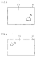
- FIG. 1 An example of such a private area is illustrated in FIG. There, the overview image 53 is displayed on the display 51.
- the reference numeral 54 denotes a private area which has been predetermined by the operator by means of the operating unit 7.
- control unit 6 can easily determine even if a large number of private areas whether and where the current field of view of the PTZ camera overlaps with one of these private areas. In the case of such an overlap, alternatively, as indicated above, only the overlapping areas or the entire image may be blackened or out of focus. Alternatively, a setting of large zoom values can also be denied with respect to these areas, ie. H. the camera does not zoom in on this area.
- Motion detectors have settings that specify areas of surveillance, permissible and impermissible directions of movement and image perspectives (the size of persons in front and behind the image).
- a problem with the use of motion detectors in connection with known PTZ cameras is that the mentioned settings relate only to a specific position of the PTZ camera. Consequently, different positions of the PTZ camera also require different settings. This is with associated with a high expenditure of time. Motion detection is not possible for unadjusted positions of the PTZ camera.
- the control according to the invention now makes it possible to specify the monitoring areas and directions, etc., in the overview image.
- Data regarding the perspective can be taken from the above-mentioned focus data memory 8, in which a kind of focus map is stored.
- a motion detection can be performed because the control unit for each position, the sizes of the overview image in the current image of the PTZ camera can convert.
- a further embodiment variant is to view the instantaneous live image of the PTZ camera as an overview image. If the mouse is clicked into this picture and a frame of the desired size is drawn, pan, tilt and zoom of the PTZ camera are adjusted by the control unit 6 in such a way that the frame defined by the frame is displayed as a complete picture. This corresponds to a mouse zoom tracking.
Abstract
Description
Die Erfindung betrifft ein Verfahren und eine Vorrichtung zur Steuerung einer schwenkbaren KameraThe invention relates to a method and a device for controlling a pivotable camera
Aus der
Aus der
Aus der
Im Unterschied zum vorstehend beschriebenen Stand der Technik erfolgt gemäß dem erfindungsgemäßen Verfahren eine genaue Steuerung einer PTZ-Kamera unter Verwendung eines Übersichtsbildes. Unter einem Übersichtsbild im Sinne der Erfindung wird ein Bild verstanden, das aus im Allgemeinen mehreren Teilbildern zusammengesetzt ist, wobei diese Teilbilder im Wesentlichen von einem Ort aus aufgenommen sind und entsprechend einer vorgegebenen mathematisch definierten Projektion in das Übersichtsbild umgerechnet werden. Für gebräuchliche Projektionen ergibt sich dabei im Übersichtsbild oftmals ein im Wesentlichen horizontales und vertikales Aneinanderreihen der Teilbilder. Das Übersichtsbild stellt damit eine nahtlose und artefaktfreie, jedoch im Allgemeinen verzerrt dargestellte Ansicht der Szene über einen im Allgemeinen beliebig großen Raumwinkelbereich dar.In contrast to the prior art described above, according to the method according to the invention, precise control of a PTZ camera is performed using an overview image. An overview image in the sense of the invention is understood to mean an image which is composed of generally several subimages, these subimages being recorded substantially from one location are and converted according to a predetermined mathematically defined projection in the overview image. For conventional projections, the overview image often results in an essentially horizontal and vertical stringing together of the partial images. The overview image thus represents a seamless and artifact-free, but generally distorted view of the scene over a generally arbitrarily large solid angle area.
Ein derartiges Übersichtsbild wird gemäß der vorliegenden Erfindung von der PTZ-Kamera selbst, welche zur Aufnahme der benötigten Teilbilder in der notwendigen Weise verschwenkt wird, oder von mindestens einer weiteren im Wesentlichem am selben Ort befindlichen Kamera erstellt und auf einem Display dargestellt. In das dargestellte Übersichtsbild wird eine Markierung eingeblendet, vorzugsweise ein Rahmen, um die momentane Blickrichtung und die momentane Zoomeinstellung der PTZ-Kamera anzuzeigen. Durch Verschieben und/oder Aufziehen des im dargestellten Übersichtsbild gezeigten Rahmens erfolgt eine Umpositionierung der PTZ-Kamera im Sinne einer Veränderung der Blickrichtung und der Zoomeinstellung der PTZ-Kamera.According to the present invention, such an overview image is produced by the PTZ camera itself, which is pivoted in the necessary manner to record the required sub-images, or by at least one further camera located substantially at the same location and displayed on a display. A marker is superimposed on the overview image shown, preferably a frame in order to display the instantaneous viewing direction and the current zoom setting of the PTZ camera. By shifting and / or winding up the frame shown in the illustrated overview image, a repositioning of the PTZ camera takes place in the sense of a change in the viewing direction and the zoom setting of the PTZ camera.
Das Verschieben und/oder Aufziehen des Rahmens im dargestellten Übersichtsbild kann unter Verwendung einer Maus erfolgen. Alternativ dazu besteht die Möglichkeit, ein Verschieben des Rahmens in Abhängigkeit vom Ausgangssignal eines Bewegungsdetektors durchzuführen.The shifting and / or mounting of the frame in the illustrated overview image can be done using a mouse. Alternatively, it is possible to perform a shifting of the frame in response to the output signal of a motion detector.
Wird das Übersichtsbild von der PTZ-Kamera selbst erstellt, dann bedarf es zur Realisierung des erfindungsgemäßen Verfahrens keiner weiteren Kamera.If the overview image is created by the PTZ camera itself, then no further camera is required to implement the method according to the invention.
Bei dem eingeblendeten Rahmen kann es sich um ein Viereck handeln, dessen Eckpunkte den vier Eckpunkten des momentanen Bildes von der PTZ-Kamera entsprechen. Alternativ dazu kann zum Zwecke einer erhöhten Genauigkeit auch ein Rahmen mit mehr Punkten dargestellt werden, wobei diese Punkte die echten Seitenlinien des PTZ-Bildes repräsentieren. Diese Seitenlinien können in Abhängigkeit von der jeweils verwendeten Projektion auch nicht geradlinig verlaufen.The displayed frame may be a quadrilateral whose vertices correspond to the four vertices of the current image from the PTZ camera. alternative For this purpose, a frame with more dots can also be displayed for the purpose of increased accuracy, these dots representing the true side lines of the PTZ image. These sidelines may not be straightforward, depending on the particular projection used.
In vorteilhafter Weise besteht die Möglichkeit, mittels der Eingabeeinheit im dargestellten Übersichtsbild einen Punkt zu markieren. Als Reaktion darauf wird die PTZ-Kamera bezüglich ihrer Blickrichtung und ihrer Zoomeinstellung derart gesteuert, dass der Mittelpunkt oder das Zoomzentrum der PTZ-Kamera auf den markierten Punkt verfahren wird. Dies ermöglicht es beispielsweise Sicherheitskräften in einem Fußballstadion, im Falle eines Abschießens von Feuerwerkskörpern an einer beliebigen Stelle des Fußballstadions durch eine schnelle Markierung eines Punktes im Übersichtsbild, der in der Nähe der Abschussstelle liegt, die PTZ-Kamera im Hinblick auf ihre Blickrichtung und ihre Zoomeinstellung schnell und automatisch an diesen Punkt zu verfahren, so dass der Übeltäter schnell identifiziert werden kann. Dies wird dadurch noch erleichtert, dass um den genannten Punkt herum ein Rahmen aufgezogen werden kann, so dass mit einem Bedienvorgang im Livebild der PTZ-Kamera auch die Umgebung der Abschussstelle automatisch in der gewünschten Größe (Zoomeinstellung) dargestellt wird.Advantageously, it is possible to mark a point by means of the input unit in the overview image shown. In response, the PTZ camera is controlled with respect to its viewing direction and zooming such that the center or zoom center of the PTZ camera is moved to the marked point. This allows, for example, security forces in a football stadium, in the event of fireworks firing anywhere in the football stadium, by quickly marking a point in the overview image that is close to the shooting site, the PTZ camera with regard to its viewing direction and zoom setting to move quickly and automatically to this point, so that the culprit can be identified quickly. This is made even easier by the fact that a frame can be wound around the said point, so that with an operation in the live image of the PTZ camera, the environment of the shooting point is automatically displayed in the desired size (zoom setting).
Vorzugsweise erfolgt die Markierung eines Punktes im Übersichtsbild und ein Aufziehen eines Rahmens im Übersichtsbild in einfacher Weise unter Verwendung einer Maus, mittels welcher der Zielpunkt angeklickt, durch Verschieben der Maus bei gedrückter Maustaste der Rahmen aufgezogen und durch das Loslassen der Maustaste die Größe des Rahmens festgelegt wird. Es ist dabei vorteilhaft, wenn der aufgezogene Rahmen in seiner Form im Übersichtsbild automatisch so angepasst wird, dass er der Form eines Teilbildes an dieser Stelle entspricht. Diese Form wird durch die Projektion definiert und hängt von dieser sowie von der Stelle im Übersichtsbild ab.Preferably, the marking of a point in the overview image and a drawing of a frame in the overview image in a simple manner using a mouse, by means of which the target point clicked, moved by moving the mouse while holding down the mouse button frame and set the size of the frame by letting go of the mouse button becomes. It is advantageous if the mounted frame in its shape in the overview image is automatically adjusted so that it corresponds to the shape of a partial image at this point. This form is defined by the projection and depends on it as well as on the location in the overview screen.
Ein Verfahren der Blickrichtung hat im Allgemeinen eine veränderte Entfernung der Objekte an der neuen Position zur Folge. Um diese scharf zu sehen, ist daher eine veränderte Fokuseinstellung notwendig. Um die Einstellung der PTZ-Kamera an das veränderte Blickfeld automatisch anpassen zu können, wird in vorteilhafter Weise von Fokusdaten Gebrauch gemacht, die in einem Fokusdatenspeicher abgelegt sind. In diesem Fokusdatenspeicher ist für jeden Bildpunkt des Übersichtsbildes ein Fokuswert hinterlegt. Daraus resultiert der Vorteil, dass es im Falle einer Veränderung der Blickrichtung der PTZ-Kamera keiner manuellen Veränderung der Fokuseinstellung der PTZ-Kamera bedarf.A viewing direction method generally results in a changed distance of the objects at the new position. In order to see these sharply, therefore, a changed focus adjustment is necessary. In order to be able to automatically adjust the setting of the PTZ camera to the changed field of view, use is advantageously made of focus data stored in a focus data memory. In this focus data memory, a focus value is stored for each pixel of the overview image. This results in the advantage that in the case of a change in the viewing direction of the PTZ camera, no manual change in the focus setting of the PTZ camera is required.
Vorzugsweise besteht des Weiteren die Möglichkeit, bezüglich des Übersichtsbildes Bildbereiche vorzugeben, die bei der Darstellung eines aktuellen Bildes der PTZ-Kamera nicht oder nur eingeschränkt einsehbar sind. Dies kann durch eine geschwärzte Darstellung oder eine unscharfe Darstellung der vorgegebenen Bildbereiche realisiert werden. Dadurch können beispielsweise im Falle einer Überwachung eines Firmengeländes Privatbereiche ausgeschlossen werden.Furthermore, it is possible to predefine image regions with respect to the overview image which are not or only partially visible when displaying a current image of the PTZ camera. This can be realized by a blackened representation or a blurred representation of the given image areas. As a result, private areas can be excluded, for example, in the case of monitoring a company premises.
Eine weitere vorteilhafte Ausgestaltung der Erfindung besteht darin, das Verschieben des Blickfeldes der PTZ-Kamera in Abhängigkeit vom Ausgangssignal eines Bewegungsdetektörs vorzunehmen, welcher das Livebild der PTZ-Kamera auswertet. Wird eine Bewegung detektiert, dann wird die PTZ-Kamera schnell und automatisch bezüglich ihrer Blickrichtung und Zoomeinstellung derart verfahren, dass die Stelle, an welcher Bewegung aufgetreten ist, in der Bildmitte des von der PTZ-Kamera gelieferten Livebildes erscheint.A further advantageous embodiment of the invention is to make the shifting of the field of view of the PTZ camera in response to the output of a Bewegungsdetektörs, which evaluates the live image of the PTZ camera. If a movement is detected, the PTZ camera is quickly and automatically moved with respect to its viewing direction and zoom setting in such a way that the point at which movement has occurred appears in the center of the image of the live image supplied by the PTZ camera.
Weitere vorteilhafte Eigenschaften der Erfindung ergeben sich aus deren nachfolgender Erläuterung anhand der Figuren. Es zeigt
Figur 1- eine Blockdarstellung zur Erläuterung eines ersten Ausführungsbeispiels für die Erfindung,
Figur 2- eine Blockdarstellung zur Erläuterung eines zweiten Ausführungsbeispiels für die Erfindung.
Figur 3- eine Skizze zur Veranschaulichung eines in ein Übersichtsbild eingeblendeten Rahmens,
Figur 4- eine Skizze zur Veranschaulichung eines privaten Bereiches in einem Übersichtsbild.
- FIG. 1
- a block diagram for explaining a first embodiment of the invention,
- FIG. 2
- a block diagram for explaining a second embodiment of the invention.
- FIG. 3
- a sketch to illustrate a frame displayed in an overview picture,
- FIG. 4
- a sketch to illustrate a private area in an overview picture.
Die vorliegende Erfindung betrifft die Steuerung einer PTZ-Kamera. Unter einer PTZ-Kamera wird dabei eine Kamera verstanden, die um eine vertikal verlaufende Achse, die sogenannte Pan-Achse, und um eine horizontal verlaufende Achse, die sogenannte Tilt-Achse, verschwenkbar ist und bei welcher die Zoomeinstellung der Kamera verändert werden kann. Gemäß der vorliegenden Erfindung wird zur Steuerung dieser PTZ-Kamera ein auf einem Display dargestelltes Übersichtsbild verwendet, in welchem eine gewünschte Stelle markiert wird. Als Reaktion auf diese Markierung wird die Blickrichtung und die Zoomeinstellung der PTZ-Kamera automatisch in dem Sinne verändert, dass die PTZ-Kamera auf die gewünschte Stelle gerichtet ist, so dass ein aktuelles Bild von der gewünschten Stelle auf einem Display betrachtet werden kann.The present invention relates to the control of a PTZ camera. A PTZ camera is understood to be a camera which can be pivoted about a vertically extending axis, the so-called pan axis, and about a horizontally extending axis, the so-called tilt axis, and in which the zoom setting of the camera can be changed. According to the present invention, an overview image displayed on a display is used to control this PTZ camera, in which a desired location is marked. In response to this marking, the viewing direction and zoom setting of the PTZ camera is automatically changed in the sense that the PTZ camera is aimed at the desired location, so that a current image can be viewed from the desired location on a display.
Die Figur 1 zeigt eine Blockdarstellung zur Erläuterung eines ersten Ausführungsbeispiels für die Erfindung. Diese Blockdarstellung offenbart eine Vorrichtung zur Steuerung einer PTZ-Kamera. Die PTZ-Kamera 1 ist auf einer Positioniereinrichtung 2 befestigt. Die Ausgangssignale der PTZ-Kamera 1 werden einer Displayeinheit 5 zugeführt. Die Displayeinheit 5 wird von einer Steuereinheit 6 angesteuert. Die Steuereinheit 6 liefert über eine Steuersignalverbindung 3 Steuersignale an die Positioniereinrichtung 2, um bei Bedarf eine horizontale und vertikale Verschwenkung der PTZ-Kamera 1 durchzuführen. Weiterhin liefert die Steuereinheit 6 über eine Steuersignalverbindung 4 Steuersignale an die PTZ-Kamera selbst, um deren Zoomeinstellung zu verändern. Ferner steht die Steuereinheit 6 mit einer Eingabeeinheit 7 und einem Fokusdatenspeicher 8 in Verbindung.1 shows a block diagram for explaining a first embodiment of the invention. This block diagram discloses a device for controlling a PTZ camera. The
Mittels der PTZ-Kamera 1 wird zunächst ein Übersichtsbild erstellt. Zu diesem Zweck wird mittels der PTZ-Kamera 1 zeitlich nacheinander und nach einer entsprechenden Umpositionierung der Kamera eine Vielzahl von Teilbildern aufgenommen und der Displayeinheit 5 zugeführt. Dort werden die Teilbilder in der oben näher beschriebenen Weise in horizontaler und vertikaler Richtung zusammengesetzt. Das dadurch entstehende Übersichtsbild wird auf dem Display der Displayeinheit 5 angezeigt. Dieses Übersichtsbild kann für einen längeren Zeitraum unverändert bleiben, es kann jedoch auch in vorgegebenen Zeitabständen, die beispielsweise in der Größenordnung einer Minute liegen, aktualisiert werden.By means of the
Ein aktuelles Livebild der PTZ-Kamera wird auf einem weiteren Display 9 dargestellt, welches in der Nähe der Displayeinheit 5 positioniert ist.A current live image of the PTZ camera is displayed on a
Zu einer Steuerung der PTZ-Kamera wird zunächst eine Markierung in das dargestellte Übersichtsbild eingeblendet, um die momentane Blickrichtung und die momentane Zoomeinstellung der PTZ-Kamera anzuzeigen. Dies ist in der Figur 3 veranschaulicht. Dort ist das Display 51 der Displayeinheit 5 gezeigt. Auf diesem Display 51 ist das Übersichtsbild 53 dargestellt, in welches ein Rahmen 52 eingeblendet ist, der die momentane Blickrichtung und die momentane Zoomeinstellung der PTZ-Kamera anzeigt. Der Rahmen zeit damit das von der Kamera momentan erfasste Blickfeld an. Die Einblendung der Markierung in das Übersichtsbild kann mittels der Eingabeeinheit 7 ausgelöst werden, welche über die Steuereinheit 6 mit der Displayeinheit 5 verbunden ist.For a control of the PTZ camera, a mark is first faded into the displayed overview image in order to display the current viewing direction and the current zoom setting of the PTZ camera. This is illustrated in FIG. There, the
Soll nun das Blickfeld der PTZ-Kamera 1 auf eine bestimmte andere Stelle gerichtet werden, dann geschieht dies durch eine Veränderung der Markierung im dargestellten Übersichtsbild.If the field of view of the
Dies kann gemäß einer ersten Ausführungsform dadurch erfolgen, dass mittels der Bedieneinheit 7, bei der es sich um eine Maus handelt, der in das Übersichtsbild eingeblendete Rahmen an die jeweils gewünschte andere Stelle des Übersichtsbildes gezogen wird.This can be done in accordance with a first embodiment in that by means of the
Gemäß einer zweiten Ausführungsform kann dies dadurch erfolgen, dass mittels der Bedieneinheit 7 die gewünschte andere Stelle im Übersichtsbild markiert wird und dann an dieser Stelle ein neuer Rahmen gewünschter Größe aufgezogen wird. Dies kann ebenfalls mittels einer Maus erfolgen, indem durch einen ersten Mausklick die gewünschte andere Stelle im Übersichtsbild markiert wird, dann bei gedrückter Maustaste um diese Stelle ein Rahmen gewünschter Größe aufgezogen und durch ein Loslassen der Maustaste festgelegt wird.According to a second embodiment, this can be done by marking the desired other location in the overview image by means of the
Diese Betätigungen der Bedieneinheit 7 werden von der Steuereinheit 6 detektiert und in Steuerbefehle umgesetzt, die der Positioniereinrichtung 2 über die Steuersignalverbindung 3 und der PTZ-Kamera 1 über die Steuersignalverbindung 4 zugeführt werden. Mittels dieser Steuersignale erfolgt eine Veränderung der Blickrichtung und der Zoomeinstellung der PTZ-Kamera.These actuations of the
Die technische Grundlage für eine derartige genaue Steuerung der PTZ-Kamera unter Verwendung eines Übersichtsbildes ist die Kenntnis des geometrischen Bezuges zwischen den möglichen Positionen im Übersichtsbild und der Pan-, Tilt- und Zoomeinstellung der PTZ-Kamera und den Positionen in deren eigenem Bild bei der jeweils vorliegenden Pan-, Tilt und Zoomeinstellung der PTZ-Kamera.The technical basis for such precise control of the PTZ camera using an overview image is the knowledge of the geometric relationship between the possible positions in the overview image and the pan, tilt and zoom setting of the PTZ camera and the positions in their own image at the Pan, tilt and zoom settings of the PTZ camera.
Um diesen Bezug herzustellen wird eine Modellierung und Kalibrierung der mechanischen (Pan-, Tilt-Mechanik) und optischen (Öffnungswinkel, Radialverzerrungen) Kameraeigenschaften sowie eine Modellierung der für das Übersichtsbild verwendeten Projektion durchgeführt.In order to establish this reference, a modeling and calibration of the mechanical (pan, tilt mechanics) and optical (opening angle, radial distortions) camera properties as well as a modeling of the projection used for the overview image is performed.
Dabei werden für die Abbildung eines Bildpunktes in einer beliebigen Pan-, Tilt-Stellung in das Übersichtsbild und umgekehrt folgende Schritte durchgeführt:The following steps are performed for the illustration of a pixel in any Pan, Tilt position in the overview image and vice versa:
Zunächst wird ein beliebiger Bildpunkt im Bild der PTZ-Kamera in einer beliebigen Pan-, Tilt-Position auf eine absolute Raumrichtung, d. h. in Weltkoordinaten, umgerechnet. Das Weltkoordinatensystem ist beliebig. Zweckmäßigerweise wird dafür das Kamerasystem für Pan = 0 und Tilt = 0 gewählt. Weiterhin wird ohne Einschränkung angenommen, dass ein System mit ortsfester Pan-Achse vorliegt.First, any pixel in the image of the PTZ camera in any pan, tilt position to an absolute spatial direction, d. H. in world coordinates, converted. The world coordinate system is arbitrary. Conveniently, the camera system for Pan = 0 and Tilt = 0 is selected. Furthermore, it is assumed without limitation that a system with fixed Pan-axis exists.
Danach werden folgende Schritte durchgeführt (erste Anweisungen):
- eine Radialentzerrung, bei welcher die Kamerabilder in entzerrte virtuelle Kamerabilder umgerechnet werden. Dabei werden Geraden exakt auf Geraden abgebildet. Die virtuelle Kamera verhält sich dann wie eine mathematisch ideale projektive Abbildung;
- optional kann ein Kameraroll korrigiert werden. Dies entspricht einer Drehung um die Längsachse. Roll kommt vor, wenn bei horizontaler Tiltstellung die vertikale Achse des Kamerachips nicht parallel zur Pan-Achse verläuft;
- Transformieren eines beliebigen Bildpunktes auf die Bildmitte. Dies kann beispielsweise unter Verwendung der in der
DE 101 32 929 B4 - Drehung der Bildmitte auf die z-Achse des Weltkoordinatensystems unter Verwendung der dem Pan und Tilt entsprechenden Drehmatrizen bei willkürlich festgelegter Nullrichtung.
- a radial equalization, in which the camera images are converted into equalized virtual camera images. Straight lines are shown exactly on straight lines. The virtual camera then behaves like a mathematically ideal projective image;
- Optionally, a camera roll can be corrected. This corresponds to a rotation about the longitudinal axis. Roll is coming when in horizontal tilt position, the vertical axis of the camera chip is not parallel to the pan axis;
- Transform any pixel to the center of the image. This can be done, for example, using the in
DE 101 32 929 B4 - Rotation of the center of the image on the z-axis of the world coordinate system using the Pan and Tilt corresponding Drehatrizen at arbitrary fixed zero direction.
Nach Durchführung dieser Schritte ist für einen gegebenen Bildpunkt im Bild der PTZ-Kamera die absolute Raumrichtung gegeben und umgekehrt.After performing these steps, the absolute spatial direction is given for a given pixel in the image of the PTZ camera, and vice versa.
Des Weiteren wir die Umrechung von Raumrichtungen in ein Übersichtsbild modelliert. Raumrichtungen entsprechen Punkten auf einer Kugel. Folglich entspricht dieses Problem dem sogenannten Atlantenproblem, d. h. einer Abbildung der Weltkugel auf ebene Karten, wobei im vorliegenden Fall eine Abbildung auf ein ebenes Display durchzuführen ist.Furthermore, we modeled the conversion of spatial directions into an overview image. Spatial directions correspond to points on a sphere. Consequently, this problem corresponds to the so-called atlas problem, i. H. an image of the globe on flat maps, in the present case an image is to be performed on a flat display.
Dazu werden folgende Schritte (zweite Anweisungen) durchgeführt, wobei sich je nach Projektionsart auch Abweichungen ergeben können:
- Festlegen einer Projektionsfläche (Zylinder, Kegel, etc.), die den Ursprung des Weltkoordinatensystems teilweise oder vollständig umgibt;
- Schneiden der berechneten Raumrichtung mit dieser Projektionsfläche;
- Abbilden der Projektionsfläche in die Ebene, beispielsweise durch ein Durchschneiden und Aufrollen des Zylinders oder Kegels;
- linear oder auch nichtlineare Skalierungen in Höhe und Breite, um den Maßstab bzw. die Pixelanzahl festzulegen. Bei Bedarf können beliebige geometrische Bildtransformationen implementiert werden, beispielsweise eine Darstellung eines Ausschnitts des Übersichtsbildes mit besonderer Genauigkeit. Dies entspricht einem elektronischen Warpen von Bildern beispielsweise für Karikaturen.
- Defining a projection surface (cylinder, cone, etc.) that partially or completely surrounds the origin of the world coordinate system;
- Cutting the calculated spatial direction with this projection surface;
- Imaging the projection surface into the plane, for example by cutting through and rolling up the cylinder or cone;
- linear or nonlinear scaling in height and width to set the scale or number of pixels. If required, any geometric image transformations can be implemented, for example a representation of a section of the overview image with particular accuracy. This corresponds to an electronic warping of images for example for cartoons.
Mittels dieser Umrechnungen kann das Verfahren gemäß der Erfindung ausgeführt werden. Für die Schritte, die die Anzeige der momentanen Kamerapositionen betreffen, werden entsprechend den oben gegebenen ersten Anweisungen die entsprechenden Bildpunkte (Randpunkte, Eckpunkte, Bildmitte und/oder Zoomzentrum) erst auf absolute Raumrichtungen umgerechnet und dann mit den oben gegebenen zweiten Anweisungen in das Übersichtsbild projiziert.By means of these conversions, the method according to the invention can be carried out. For the steps which relate to the display of the current camera positions, the corresponding pixels (edge points, corner points, center of the image and / or zoom center) are first converted to absolute spatial directions and then projected into the overview image with the second instructions given above, in accordance with the first instructions given above ,
Für die Schritte, die die Steuerung der Kamera betreffen, wird umgekehrt eine gegebene Position im Übersichtsbild erst mittels der zweiten Anweisungen in eine absolute Raumrichtung umgerechnet. Unter Umkehrung des letzten Schrittes der ersten Anweisungen können dann die Pan- und Tilt-Werte ermittelt werden, die diesen Punkt zum neuen Bildmittelpunkt machen. Für diesen neuen Mittelpunkt und die momentane Zoomeinstellung kann wie im vorhergehenden Abschnitt der Rahmen des momentanen Blickfeldes berechnet und angezeigt werden. Soll auch die Zoomeinstellung, etwa durch ein Ziehen der Maus, angepasst werden, so kann durch das Ziehen der Maus die Zoomeinstellung virtuell verändert und der dazugehörige Rahmen eingeblendet werden. Erscheint der durch den Rahmen angezeigte Ausschnitt geeignet, Wird beispielsweise durch ein Loslassen der Maustaste die Kamera tatsächlich auf diese Einstellung verfahren. Die Veränderung des virtuellen Zooms kann dabei derart erfolgen, dass der neue Öffnungswinkel dem Winkel zwischen den absoluten Raumrichtungen des neuen Mittelpunkts und der aktuellen Mausposition während des Ziehens entspricht. Der angezeigte Rahmen hat dann zum einen die korrekte geometrische Form eines Teilbildes und geht zum anderen in etwa durch die aktuelle Mausposition.Conversely, for the steps relating to the control of the camera, a given position in the overview image is first converted into an absolute spatial direction by means of the second instructions. By reversing the last step of the first instructions, the pan and tilt values can then be determined which make this point the new center of the image. For this new center point and the current zoom setting, as in the previous section, the frame of the current field of view can be calculated and displayed. If you also want to adjust the zoom setting, for example by dragging the mouse, you can virtually change the zoom setting by dragging the mouse and the corresponding frame can be displayed. If the section indicated by the frame appears suitable, for example, by releasing the Actually, move the camera to this setting. The change of the virtual zoom can take place such that the new opening angle corresponds to the angle between the absolute spatial directions of the new center and the current mouse position during the drawing. The displayed frame then has on the one hand the correct geometric shape of a partial image and on the other hand approximately goes through the current mouse position.
Die Figur 2 zeigt eine Blockdarstellung zur Erläuterung eines zweiten Ausführungsbeispiels für die Erfindung. Dieses zweite Ausführungsbeispiel unterscheidet sich von dem in der Figur 1 dargestellten Ausführungsbeispiel dadurch, dass die einzelnen Teilbilder, aus denen das Übersichtsbild zusammengesetzt wird, nicht von der PTZ-Kamera 1, sondern von einer weiteren Kamera 10 erstellt werden. Alternativ dazu können zur Erstellung der Teilbilder, aus denen das Übersichtsbild zusammengesetzt ist, auch mehrere weitere Kameras verwendet werden.2 shows a block diagram for explaining a second embodiment of the invention. This second exemplary embodiment differs from the exemplary embodiment illustrated in FIG. 1 in that the individual partial images from which the overview image is composed are not produced by the
Die weiteren Kameras befinden sich daher relativ zu den Entfernungen der Objekte in der Szene im Wesentlichen am selben Ort. Auf diese Weise können die genauen Objektentfernungen beim Erstellen des Übersichtsbildes unberücksichtigt und unbekannt bleiben.The other cameras are therefore located at substantially the same location relative to the distances of the objects in the scene. In this way, the exact object distances when creating the overview image can be disregarded and unknown.
In vorteilhafter Weise ist bei beiden vorgenannten Ausführungsbeispielen im Fokusdatenspeicher 8 für jeden Bildpunkt des Übersichtsbildes ein Fokuswert hinterlegt. Dieser Fokuswert wird beim Anfahren einer zugehörigen Position der PTZ-Kamera von der Steuereinheit 6 aus dem Fokusdatenspeicher 8 abgerufen und bei der Ermittlung der Steuersignale für die PTZ-Kamera berücksichtigt. Der Fokuswert entspricht dabei der zuvor ermittelten Objektentfernung an dieser Position.Advantageously, a focus value is stored in the
Eine vorteilhafte Weiterbildung der Erfindung besteht darin, im Übersichtsbild private Bereich anzugeben, so dass der aktuelle Bildinhalt dieser Bereiche im Livebild der PTZ-Kamera nicht oder nur eingeschränkt einsehbar ist. Beispielsweise können diese privaten Bereiche im Livebild der PTZ-Kamera geschwärzt oder unscharf dargestellt werden.An advantageous development of the invention is to specify in the overview image private area, so that the current image content of these areas in the live image of the PTZ camera is not or only partially visible. For example, these private areas in the live image of the PTZ camera can be blacked out or out of focus.
Ein Beispiel für einen derartigen privaten Bereich ist in der Figur 4 veranschaulicht. Dort wird auf dem Display 51 das Übersichtsbild 53 angezeigt. Mit der Bezugszahl 54 ist ein privater Bereich bezeichnet, der vom Bediener mittels der Bedieneinheit 7 vorgegeben wurde.An example of such a private area is illustrated in FIG. There, the
Durch die oben beschriebene geometrische Kopplung kann von der Steuereinheit 6 selbst bei einer großen Anzahl von privaten Bereichen in einfacher Weise festgestellt werden, ob und wo das momentane Blickfeld der PTZ-Kamera mit einem dieser privaten Bereiche überlappt. Im Falle einer derartigen Überlappung können - wie bereits oben angegeben - alternativ nur die überlappenden Bereiche oder das ganze Bild geschwärzt oder unscharf dargestellt werden. Alternativ dazu kann auch bezüglich dieser Bereiche eine Einstellung großer Zoomwerte verweigert werden, d. h. die Kamera lässt sich nicht in diese Bereich hineinzoomen.By the above-described geometric coupling, the
Eine andere vorteilhafte Weiterbildung besteht darin, das Verschieben und/oder Aufziehen eines Rahmens im dargestellten Übersichtsbild in Abhängigkeit von den Ausgangssignalen eines Bewegungsdetektors durchzuführen. Bewegungsdetektoren haben Einstellungen, welche Überwachungsbereiche, zulässige und unzulässige Bewegungsrichtungen und Bildperspektiven (Größe von Personen vorne und hinten im Bild) festlegen. Ein Problem bei der Anwendung von Bewegungsdetektoren im Zusammenhang mit bekannten PTZ-Kameras besteht darin, dass die genannten Einstellungen sich nur auf eine bestimmte Position der PTZ-Kamera beziehen. Folglich benötigen verschiedene Positionen der PTZ-Kamera auch verschiedene Einstellungen. Dies ist mit hohem Zeitaufwand verbunden. Für nicht eingestellte Positionen der PTZ-Kamera ist keine Bewegungsdetektion möglich. Die erfindungsgemäße Steuerung ermöglicht es nunmehr, die Überwachungsbereiche und Richtungen, etc., im Übersichtsbild anzugeben. Daten bezüglich der Perspektive können dem oben genannten Fokusdatenspeicher 8 entnommen werden, in welchem eine Art Fokuskarte abgespeichert ist. Damit kann in jeder Stellung von Pan, Tilt und Zoom der PTZ-Kamera eine Bewegungsdetektion durchgeführt werden, da die Steuereinheit für die jeweilige Stellung die Größen vom Übersichtsbild in das momentane Bild der PTZ-Kamera umrechnen kann.Another advantageous development is to carry out the shifting and / or mounting of a frame in the illustrated overview image as a function of the output signals of a motion detector. Motion detectors have settings that specify areas of surveillance, permissible and impermissible directions of movement and image perspectives (the size of persons in front and behind the image). A problem with the use of motion detectors in connection with known PTZ cameras is that the mentioned settings relate only to a specific position of the PTZ camera. Consequently, different positions of the PTZ camera also require different settings. This is with associated with a high expenditure of time. Motion detection is not possible for unadjusted positions of the PTZ camera. The control according to the invention now makes it possible to specify the monitoring areas and directions, etc., in the overview image. Data regarding the perspective can be taken from the above-mentioned
Eine weitere Ausführungsvariante besteht darin, das momentane Livebild der PTZ-Kamera als ein Übersichtsbild zu betrachten. Wird in dieses Bild mittels der Maus hineingeklickt und ein Rahmen gewünschter Größe aufgezogen, dann werden Pan, Tilt und Zoom der PTZ-Kamera von der Steuereinheit 6 so eingestellt, dass der durch Rahmen definierte Bildausschnitt als komplettes Bild dargestellt wird. Dies entspricht einem Maus-Zoom-Tracking.A further embodiment variant is to view the instantaneous live image of the PTZ camera as an overview image. If the mouse is clicked into this picture and a frame of the desired size is drawn, pan, tilt and zoom of the PTZ camera are adjusted by the
Claims (28)
Applications Claiming Priority (1)
| Application Number | Priority Date | Filing Date | Title |
|---|---|---|---|
| DE102006048006A DE102006048006A1 (en) | 2006-10-09 | 2006-10-09 | Control method for pan-tilt-zoom (PTZ) camera, involves changing marking inserted in displayed summary image on display unit to change line of sight and zooming position of PTZ camera |
Publications (2)
| Publication Number | Publication Date |
|---|---|
| EP1912431A2 true EP1912431A2 (en) | 2008-04-16 |
| EP1912431A3 EP1912431A3 (en) | 2010-07-07 |
Family
ID=38973145
Family Applications (1)
| Application Number | Title | Priority Date | Filing Date |
|---|---|---|---|
| EP07117457A Withdrawn EP1912431A3 (en) | 2006-10-09 | 2007-09-28 | Method and device for actuating a pivotable camera |
Country Status (2)
| Country | Link |
|---|---|
| EP (1) | EP1912431A3 (en) |
| DE (1) | DE102006048006A1 (en) |
Cited By (4)
| Publication number | Priority date | Publication date | Assignee | Title |
|---|---|---|---|---|
| WO2018120012A1 (en) * | 2016-12-30 | 2018-07-05 | 深圳市大疆灵眸科技有限公司 | Method and device for controlling cradle head, and cradle head |
| WO2020062298A1 (en) * | 2018-09-30 | 2020-04-02 | 深圳市大疆创新科技有限公司 | Gimbal and control method therefor, and movable platform |
| CN113169630A (en) * | 2020-10-27 | 2021-07-23 | 深圳市大疆创新科技有限公司 | Control method of focus following wheel, focus following wheel and storage medium |
| WO2022261907A1 (en) * | 2021-06-17 | 2022-12-22 | 深圳市大疆创新科技有限公司 | Control method for follow focus device, and device and storage medium |
Citations (7)
| Publication number | Priority date | Publication date | Assignee | Title |
|---|---|---|---|---|
| WO1994008424A1 (en) * | 1992-10-02 | 1994-04-14 | International Business Machines Corporation | Method and apparatus for controlling a camera |
| US20010019355A1 (en) * | 1997-04-21 | 2001-09-06 | Masakazu Koyanagi | Controller for photographing apparatus and photographing system |
| US20010040636A1 (en) * | 1994-11-17 | 2001-11-15 | Eiji Kato | Camera control and display device using graphical user interface |
| DE10158990C1 (en) * | 2001-11-30 | 2003-04-10 | Bosch Gmbh Robert | Video surveillance system incorporates masking of identified object for maintaining privacy until entry of authorisation |
| EP1363255A2 (en) * | 2002-05-15 | 2003-11-19 | Sony Corporation | Monitoring system, monitoring method and imaging apparatus |
| EP1455525A1 (en) * | 2003-03-05 | 2004-09-08 | TELCAST Media Group GmbH | Method and device for recording videodata |
| US20060064384A1 (en) * | 2004-09-15 | 2006-03-23 | Sharad Mehrotra | Apparatus and method for privacy protection of data collection in pervasive environments |
-
2006
- 2006-10-09 DE DE102006048006A patent/DE102006048006A1/en not_active Withdrawn
-
2007
- 2007-09-28 EP EP07117457A patent/EP1912431A3/en not_active Withdrawn
Patent Citations (7)
| Publication number | Priority date | Publication date | Assignee | Title |
|---|---|---|---|---|
| WO1994008424A1 (en) * | 1992-10-02 | 1994-04-14 | International Business Machines Corporation | Method and apparatus for controlling a camera |
| US20010040636A1 (en) * | 1994-11-17 | 2001-11-15 | Eiji Kato | Camera control and display device using graphical user interface |
| US20010019355A1 (en) * | 1997-04-21 | 2001-09-06 | Masakazu Koyanagi | Controller for photographing apparatus and photographing system |
| DE10158990C1 (en) * | 2001-11-30 | 2003-04-10 | Bosch Gmbh Robert | Video surveillance system incorporates masking of identified object for maintaining privacy until entry of authorisation |
| EP1363255A2 (en) * | 2002-05-15 | 2003-11-19 | Sony Corporation | Monitoring system, monitoring method and imaging apparatus |
| EP1455525A1 (en) * | 2003-03-05 | 2004-09-08 | TELCAST Media Group GmbH | Method and device for recording videodata |
| US20060064384A1 (en) * | 2004-09-15 | 2006-03-23 | Sharad Mehrotra | Apparatus and method for privacy protection of data collection in pervasive environments |
Cited By (8)
| Publication number | Priority date | Publication date | Assignee | Title |
|---|---|---|---|---|
| WO2018120012A1 (en) * | 2016-12-30 | 2018-07-05 | 深圳市大疆灵眸科技有限公司 | Method and device for controlling cradle head, and cradle head |
| US11086202B2 (en) | 2016-12-30 | 2021-08-10 | Sz Dji Osmo Technology Co., Ltd. | Gimbal control method, device, and gimbal |
| US11852958B2 (en) | 2016-12-30 | 2023-12-26 | Sz Dji Osmo Technology Co., Ltd. | Gimbal control method, device, and gimbal |
| WO2020062298A1 (en) * | 2018-09-30 | 2020-04-02 | 深圳市大疆创新科技有限公司 | Gimbal and control method therefor, and movable platform |
| CN113169630A (en) * | 2020-10-27 | 2021-07-23 | 深圳市大疆创新科技有限公司 | Control method of focus following wheel, focus following wheel and storage medium |
| WO2022087828A1 (en) * | 2020-10-27 | 2022-05-05 | 深圳市大疆创新科技有限公司 | Follow focus wheel control method, follow focus wheel, and storage medium |
| CN113169630B (en) * | 2020-10-27 | 2022-07-19 | 深圳市大疆创新科技有限公司 | Control method of focus following wheel, focus following wheel and storage medium |
| WO2022261907A1 (en) * | 2021-06-17 | 2022-12-22 | 深圳市大疆创新科技有限公司 | Control method for follow focus device, and device and storage medium |
Also Published As
| Publication number | Publication date |
|---|---|
| DE102006048006A1 (en) | 2008-04-10 |
| EP1912431A3 (en) | 2010-07-07 |
Similar Documents
| Publication | Publication Date | Title |
|---|---|---|
| EP2464098B1 (en) | Vicinity presentation device, a vehicle with such a vicinity presentation device and method for displaying a panorama image | |
| DE19825302B4 (en) | System for creating a three-dimensional garbage mat, which allows a simplified adjustment of spatial relationships between real and virtual scene elements | |
| EP2880853B1 (en) | Apparatus and method for determining the distinct location of an image-recording camera | |
| EP3427474B1 (en) | Image processing method, image processing means and image processing device for generating images of a portion of a three-dimensional space | |
| DE19815106B4 (en) | Method for measuring camera and lens characteristics for camera tracking | |
| WO2007104367A1 (en) | Video monitoring system | |
| DE102016124978A1 (en) | Virtual representation of an environment of a motor vehicle in a driver assistance system with a plurality of projection surfaces | |
| EP1912431A2 (en) | Method and device for actuating a pivotable camera | |
| DE102006036769B3 (en) | Airplane real time-aerial view-monitoring device, has cameras with fields of view adjusted by one camera by compensator such that format of resultant image is switched between strip receiver and point or sport receiver | |
| DE69721520T2 (en) | System with a photosensor, in particular for time measurement in competitions, and setting method for aligning such a system to a finish line | |
| AT521845B1 (en) | Method for adjusting the focus of a film camera | |
| EP0976003A1 (en) | Optical imaging system and graphic user interface | |
| WO2018133996A1 (en) | Method for combining a plurality of camera images | |
| DE19825837B4 (en) | Method and device for controlling lighting installations | |
| EP2884746A1 (en) | Monitoring camera device with depth information determination | |
| WO2004082266A1 (en) | Method and device for recording video data | |
| DE60108918T2 (en) | Interactive method and apparatus for video broadcasting of a moving video camera | |
| EP1434184B1 (en) | Control of a multicamera system | |
| DE102012217148A1 (en) | Client device for displaying camera images of a controllable camera, method, computer program and monitoring system with the client device | |
| DE102014105011B4 (en) | System for visualizing the field of view of an optical device | |
| DE102010026572A1 (en) | Method for recording and performing playback of panorama images, involves projecting image signals on virtual projection surface which corresponds to inverted surface of optical mirror component of camera system | |
| EP2424225B1 (en) | Imaging system and method for detecting an object | |
| EP3185213A1 (en) | Method for creating a depth map by means of a camera | |
| DE102004044002A1 (en) | Real-time movement analysis device e.g. for recording sporting events, uses image processing unit in data exchange with cameras | |
| EP1296213A1 (en) | Method and apparatus for guiding an unmanned aerial vehicle |
Legal Events
| Date | Code | Title | Description |
|---|---|---|---|
| PUAI | Public reference made under article 153(3) epc to a published international application that has entered the european phase |
Free format text: ORIGINAL CODE: 0009012 |
|
| AK | Designated contracting states |
Kind code of ref document: A2 Designated state(s): AT BE BG CH CY CZ DE DK EE ES FI FR GB GR HU IE IS IT LI LT LU LV MC MT NL PL PT RO SE SI SK TR |
|
| AX | Request for extension of the european patent |
Extension state: AL BA HR MK RS |
|
| PUAL | Search report despatched |
Free format text: ORIGINAL CODE: 0009013 |
|
| AK | Designated contracting states |
Kind code of ref document: A3 Designated state(s): AT BE BG CH CY CZ DE DK EE ES FI FR GB GR HU IE IS IT LI LT LU LV MC MT NL PL PT RO SE SI SK TR |
|
| AX | Request for extension of the european patent |
Extension state: AL BA HR MK RS |
|
| AKY | No designation fees paid | ||
| STAA | Information on the status of an ep patent application or granted ep patent |
Free format text: STATUS: THE APPLICATION IS DEEMED TO BE WITHDRAWN |
|
| 18D | Application deemed to be withdrawn |
Effective date: 20110108 |