EP1912411A1 - Method and system for service preparation of a residential network access device - Google Patents
Method and system for service preparation of a residential network access device Download PDFInfo
- Publication number
- EP1912411A1 EP1912411A1 EP06021448A EP06021448A EP1912411A1 EP 1912411 A1 EP1912411 A1 EP 1912411A1 EP 06021448 A EP06021448 A EP 06021448A EP 06021448 A EP06021448 A EP 06021448A EP 1912411 A1 EP1912411 A1 EP 1912411A1
- Authority
- EP
- European Patent Office
- Prior art keywords
- network access
- network
- residential
- address
- access device
- Prior art date
- Legal status (The legal status is an assumption and is not a legal conclusion. Google has not performed a legal analysis and makes no representation as to the accuracy of the status listed.)
- Granted
Links
Images

Classifications
-
- H—ELECTRICITY
- H04—ELECTRIC COMMUNICATION TECHNIQUE
- H04L—TRANSMISSION OF DIGITAL INFORMATION, e.g. TELEGRAPHIC COMMUNICATION
- H04L12/00—Data switching networks
- H04L12/28—Data switching networks characterised by path configuration, e.g. LAN [Local Area Networks] or WAN [Wide Area Networks]
- H04L12/2803—Home automation networks
- H04L12/2807—Exchanging configuration information on appliance services in a home automation network
- H04L12/2814—Exchanging control software or macros for controlling appliance services in a home automation network
-
- H—ELECTRICITY
- H04—ELECTRIC COMMUNICATION TECHNIQUE
- H04L—TRANSMISSION OF DIGITAL INFORMATION, e.g. TELEGRAPHIC COMMUNICATION
- H04L41/00—Arrangements for maintenance, administration or management of data switching networks, e.g. of packet switching networks
- H04L41/08—Configuration management of networks or network elements
- H04L41/0803—Configuration setting
- H04L41/0806—Configuration setting for initial configuration or provisioning, e.g. plug-and-play
-
- H—ELECTRICITY
- H04—ELECTRIC COMMUNICATION TECHNIQUE
- H04L—TRANSMISSION OF DIGITAL INFORMATION, e.g. TELEGRAPHIC COMMUNICATION
- H04L61/00—Network arrangements, protocols or services for addressing or naming
- H04L61/50—Address allocation
- H04L61/5007—Internet protocol [IP] addresses
-
- H—ELECTRICITY
- H04—ELECTRIC COMMUNICATION TECHNIQUE
- H04L—TRANSMISSION OF DIGITAL INFORMATION, e.g. TELEGRAPHIC COMMUNICATION
- H04L2101/00—Indexing scheme associated with group H04L61/00
- H04L2101/60—Types of network addresses
- H04L2101/618—Details of network addresses
- H04L2101/622—Layer-2 addresses, e.g. medium access control [MAC] addresses
Definitions
- the invention relates to the field of providing network services to customers. More particularly, the invention relates to the field of service preparation of a residential network access device in order to enable customers to enjoy a network service after said service preparation.
- IP telephony As an alternative for conventional plain old telephony systems (POTS).
- POTS plain old telephony systems
- IP telephony services typically require a residential network access device to adapt the outbound voice information to the IP telephony network and the inbound voice information to the requirements of the conventional telephone.
- network access devices are often complicated and require considerable preparation efforts from a user before the IP telephony service can be enjoyed.
- An example of such a residential network access device is disclosed in US 2006/079280 . Similar problems are encountered for other types of IP services.
- a method of service preparation of a residential network access device from one or more remote provisioning devices is proposed in order to prepare the residential network access device to receive a network service over a communications network.
- a line identifier is received indicating a physical line used by said residential network access device to connect to said communication network.
- An IP address is transmitted from said one or more provisioning devices to said residential network access device for which said line identifier has been received.
- the IP address is intended to function as a source address of the residential network access device.
- software code portions are transmitted to said IP address of said residential network access device, said software code portions being required for receiving said network service.
- a system for service preparation of a residential network access device to receive a network service over a communications network.
- the system comprises one or more remote provisioning devices and a network access node device arranged for establishing a communicative connection between a plurality of said residential network access devices and said one or more remote provisioning devices.
- the one or more provisioning devices are arranged for receiving a line identifier from said network access node device indicating a physical line used by said residential network access device to connect to said communication network.
- the provisioning devices are further arranged for transmitting an IP address from said one or more provisioning devices to said residential network access device for which said line identifier has been received.
- the IP address is intended to function as a source address of said residential network access device.
- the one or more provisioning devices are arranged to transmit software code portions to said IP address of said residential network access device, said software code portions being required for receiving said network service.
- the method and system as defined above realize a plug-and-play residential network access device.
- the connection of the residential network access device at a dwelling of a customer triggers the transmission of the line identifier via which the residential network access device connects to a network access node device from this network access node device to a provisioning device of the network service provider or an associated third party.
- This line identifier is valuable location information for customer relation services (e.g. billing) and location dependent services (e.g. routing of emergency calls to the nearest emergency centre).
- an IP address is assigned to the residential network access device from a provisioning device in order to allow transmission of further functional data to the residential network access device. This functional data prepares the residential network access device for performing functions related to the desired network service.
- the only action required by a customer desiring to enjoy a network service is to plug the residential network device into the appropriate connection in his dwelling after which an automatic installing and authorisation/registration process is performed requiring no further involvement of the customer.
- no additional actions are expected from the customer that go beyond the simple connection of a POTS telephone.
- the residential network access device may be an off-the-shelf device that requires no assignment of customer specific information to the residential network access device before connection to the network.
- the residential network access device only stores a device identifier, such as a MAC address, and is further capable of notifying the network access node device of its connection.
- the MAC address pertains to general data not linked to any specific customer. Consequently, provisioning and changing of residential network access devices is simple.
- the embodiment of the invention as defined in claims 3 and 14 is advantageous in that the MAC address bridges the gap between the physical line identifier via which the residential network access device connects to the communication network and the IP address received from the provisioning device. This is particularly advantageous in a combined Ethernet - IP communication network, as the Ethernet part of the communication network is transparent for the IP address.
- the embodiments of the invention as defined in claims 4-6, 8-10 and 18-20 are advantageous in that that a communication network is provided that uses and couples information from various layers of the Internet model (layer 1: physical line identifier; layer 2: MAC address; layer 3: IP address; higher layers: customer credentials) to advantage.
- the embodiments may also proof to be functional for preventing nomadic use of the residential network access device. The latter function may be relevant for location dependent services.
- a residential network access device hereinafter also referred to as RNAD, is illustrated that is connected to a communication network 2.
- the RNAD 1 comprises an adaptor 3 and a fibre network terminator 4 and is capable of being connected to a conventional (copper) wired telephone 5.
- the adaptor 3 and the fibre network terminator 4 are not necessarily integrated in a single device.
- the fibre network terminator 4 may provide RJ45 connections for connection of the adaptor 3.
- the adaptor 3 when properly configured according to the below described method, is capable of providing an IP telephony network service (VoIP) for the conventional telephone 5 over the communication network 2.
- VoIP IP telephony network service
- the fibre network terminator 4 provides Ethernet access for the customer of the RNAD 1.
- the functionality of the fibre network terminator 4 is limited to providing access on Ethernet level via one or more virtual local area networks (VLANs).
- the fibre network terminator 4 comprises further connections for receiving other services over the communication network that will not be described further.
- the RNAD 1 is communicatively connected by a fibre 6 to the communication network 2 by a fibre access node device 7.
- the fibre access node device 7 comprises a fibre access card with inputs 8 for further fibres of further RNADs (not shown).
- the fibre access node device 7 may be capable of receiving fibres of several hundreds of RNADs 1.
- the VLANs of the RNADs 1 are mapped on a VLAN connection to an IP edge router 11 for IP routing with provisioning devices as will be further described below.
- the communication network 2 comprises an Ethernet part 9 and an IP part 10, said parts being separated by the edge router 11.
- the communication network 2 further comprises a plurality of provisioning devices 12-14.
- the provisioning device 12 may be a server, connected to the router 11, that is capable of assigning IP addresses to devices over the communication network 2, such as a Dynamic Host Configuration Protocol (DHCP) server.
- DHCP Dynamic Host Configuration Protocol
- Provisioning device 13 is a management server taking care of the actual preparation of the RNAD 1 for receiving the IP telephony service over the communication network 2.
- Provisioning device 14 is an IP multimedia subsystem (IMS) providing the IP telephony service by voice emulation after preparation of the RNAD 1 for receiving this service.
- IMS uses open standard IP protocols, defined by the IEFT, and is capable of providing IP based services, such as VoIP.
- the IMS 14 employs a telephony application server (not shown individually) that uses the Session Initiation Protocol (SIP) for call session control of the RNAD 1.
- SIP Session Initiation Protocol
- SIP Session Initiation Protocol
- SIP Session Initiation Protocol
- SIP is an application layer signaling peer-to-peer protocol for creating, modifying and terminating sessions, such as IP telephone calls.
- SIP is specified in RFC 3261 of the IEFT SIP Working Group. It should be appreciated, however, that other signaling protocols, such as H.248, may be used.
- the system illustrated in FIG. 1 may contain further devices or systems for executing further functions, including, but not limited to, couplings for the IMS 14 to an existing conventional PSTN network (bridge-to-voice), systems for billing, maintenance, service etc. and a Session Border Controller (SBC).
- a SBC is a device used in some IP telephony networks for exerting control over the signaling and media streams involved in setting up, conducting, and tearing down calls. SBCs are put into the signaling and/or media path between a calling and a called party and may split a SIP signalling stream and a RTP media stream.
- a customer desiring to receive IP telephony network services for a service provider may obtain a RNAD 1 or an adaptor 3 as shown schematically in FIG. 2.
- the dwelling of the customer may already contain a fibre network terminator 4, such that only an adaptor 3 is required for receiving the IP telephony service.
- the adaptor 3 comprises a first connection 20 for the conventional telephone 5 and a second connection 21 for a fibre connection to the fibre network terminator 4 and further to the network access node device 7 over the fibre 6.
- the adaptor 3 further comprises a processor 22 and a memory 23.
- the processor 22 is arranged for converting SIP controlled IP telephony signals from the IMS 14 into conventional POTS signals for the telephone 5 by emulation of a POTS service and vice versa.
- the memory 23 stores a device identifier, such as a unique media access control (MAC) address. Furthermore, the memory may store further data obtained in the method described below.
- the memory 23 may be flash memory capable of storing configuration data. For such an RNAD 1, power failure does not directly require anew service preparation of the RNAD 1.
- FIG. 3 shows a first example of a communication diagram for performing a method for service preparation of the RNAD 1 over the communication network 2 of FIG. 1 according to an embodiment of the invention.
- a DHCP request is then automatically triggered and transmitted to the fibre access node device 7.
- the request 31 may include the MAC identifier of the RNAD 1 and other credentials of the RNAD 1, such as a serial number.
- the request may be a broadcast request to DHCP servers 12 listening in the communication network 2 for this request in order to provide an IP address to the RNAD 1.
- the RNAD 1 may have a specific URL 12 of a DHCP server 12 stored in its memory 23.
- the fibre access node device 7 analyses the line ID, indicating the port used by the physical line, i.e. the fibre 6, over which the DHCP request is received. This line ID is stored in the fibre access node device 7 together with the MAC address of the RNAD 1 via Ethernet learning. The line ID is not known at the RNAD 1 and thus is only available in the communication network 2. The MAC address is unique within the fibre access node device 7. The fibre access node device 7 then forwards the DHCP request in step 32 to the DHCP server 12.
- the DHCP server 12 comprises a configuration table of IP addresses corresponding to the line ID's in the various fibre access node devices 7.
- the DHCP server 12 selects the IP address corresponding to the line ID of fibre 6 and returns the IP address in step 33 to the RNAD 1.
- the IP source address is assigned to the RNAD 1.
- the router 11 intercepts and stores the MAC address of RNAD 1 in, combination with the selected IP address. Furthermore, a network address URL 13 of the management server 13 is returned to the RNAD 1.
- the DHCP server 12 communicates the assigned IP source address to the management server 13.
- the assigned IP address may also be communicated to IMS 14 (not shown), if the IP address is used for authentication purposes in IMS 14.
- step 35 a request containing the MAC address of RNAD 1 is received at the management server 13 with URL 13 from the RNAD 1 for network service preparation.
- the management server 13 is already aware of the IP source address of the RNAD 1, since this address was obtained in step 34 from the DHCP server 12.
- the management server 13 transmits voice emulation software code portions to the assigned IP address of RNAD 1 for loading in the firmware of the RNAD 1.
- the software code portions are required for receiving the IP telephony network service.
- the RNAD 1 receives customer specific credentials from the management server 13, including a public ID (e.g. a E.164 telephone number and a host domain), a private ID (a customer number to be used, e.g., for billing purposes) and possible other information such as a digit map.
- the public ID may e.g. be retrieved from a table storing relations between assigned IP source addresses for the RNAD 1 with a corresponding E.164 telephone number.
- the RNAD 1 receives a further network address, URL 14, of the IMS server 14.
- a trusted connection may be arranged between the RNAD 1 and the management server 13 on the basis of an encrypted identifier.
- step 37 the management server 13 communicates the assigned credentials, e.g. public ID and private ID, to the IMS 14. This step may be omitted if the management server 13 has received the IP source address of the RNAD 1 from the DHCP server 12.
- the RNAD 1 contacts the IMS 14 via URL 14 for the first time by transmitting the received credentials, such as the public ID and private ID, to the IMS 14.
- a customer specific service profile is established for the RNAD 1 with the line identifier of the fibre 6.
- the IMS 14 may act either on the basis of the credentials if these are trusted or also check the IP source address of the RNAD 1 if the IP source address has been provided to IMS 14.
- the RNAD 1 is signalled that the IP telephony service is ready. From this moment on, the customer may initiate or receive IP telephone calls with his conventional telephone 5.
- the SIP standardised challenge mechanism may provide for a secure relation between the RNAD 1 and the IMS 14.
- FIG. 4 shows a second example of a communication diagram for performing a method for service preparation of the RNAD 1 over the communication network 2 of FIG. 1 according to an embodiment of the invention.
- the DHCP server 12 dynamically assigns IP source addresses to the RNADs 1.
- Such an embodiment may prove to be advantageous with regard to the scalability of the system, since the DHCP server 12 no longer contains a configuration table with a reserved IP address for each line identifier.
- a DHCP broadcast request is then automatically triggered and transmitted to the fibre access node device 7.
- the request 31 may include the MAC identifier of the RNAD 1 and other credentials of the RNAD 1, such as a serial number.
- the fibre access node device 7 analyses the line ID, indicating the port used by the physical line, i.e. the fibre 6, over which the request is received. This line ID is stored in the fibre access node 7 together with the MAC address of the RNAD 1 via Ethernet learning and is not available to the RNAD 1.
- the MAC address is unique within the fibre access node 7.
- the fibre access node 7 forwards the DHCP request in step 42 to the DHCP server 12.
- the DHCP server 12 now assigns a dynamic IP source address to the RNAD 1 in step 43 as opposed to the method as described with reference to FIG. 3.
- the DHCP server 12 stores the assigned IP address and the associated line ID.
- the router 11 intercepts and stores the MAC address of RNAD 1 in combination with the assigned IP address. Furthermore, a network address URL 13 of the management server 13 is returned in step 43.
- step 44 a request containing the MAC address of RNAD 1 is received at the management server 13 from the RNAD 1 for network service preparation.
- step 45 the management server 13 transmits a request to DHCP server 12 to check whether DHCP server 12 assigned an IP source address to RNAD 1 in step 43.
- step 46 the assignment of such an IP source address is confirmed by the DHCP server 12 to the management server 13.
- the management server 13 transmits voice emulation software code portions to the dynamically assigned IP address of RNAD 1 for loading in the firmware of the RNAD 1.
- the software code portions are required for receiving the IP telephony network service.
- the RNAD 1 receives customer specific credentials from the management server 13, including a public ID (e.g. a E.164 telephone number and a host domain), a private ID (a customer number to be used, e.g. for billing purposes) and possible other information such as a digit map.
- the RNAD 1 receives a further network address, URL 14, of the IMS server 14.
- a trusted connection may be obtained on the basis of an encrypted identifier.
- step 48 the management server 13 communicates the assigned credentials, e.g. the public ID and private ID, to the IMS 14.
- the assigned credentials e.g. the public ID and private ID
- the RNAD 1 contacts the IMS 14 for the first time by transmitting the public ID and private ID, to the IMS 14.
- a customer specific service profile is established for the RNAD 1 with the line identifier of the fibre 6.
- the RNAD 1 is signalled that the IP telephony service is ready. From this moment on, the customer may initiate or receive IP telephone calls with his conventional telephone 5.
- the SIP standardised challenge mechanism may provide for a secure relation between the RNAD 1 and the IMS 14.
- the action for the customer is limited to plugging the RNAD 1, or the adaptor 3 if a fibre network terminator 4 is already installed, in the appropriate connection.
- This action corresponds to connecting a POTS device to a conventional telecommunication network.
- the further preparation of the RNAD 1 to a service ready state is fully automatic.
- the part of the communication network 2 ranging from the fibre access node device 7 to the provisioning devices 12-14 and further is what is referred to as a 'trusted' communication network.
- source identifiers of traffic such as the line ID
- source identifiers from the RNAD 1 can be manipulated on various levels (physically, e.g. by reconnecting fibres to other ports or on another level, e.g. spoofing of the MAC address of an RNAD 1 by another user) and is 'untrusted'.
- Both the line ID of the RNAD 1 and the IP address assigned to the RNAD 1 are trusted parameters, since these are assigned by the fibre access node device 7 and the DHCP server 12, respectively, which are in the trusted part of the communication network 2.
- the MAC address of the RNAD 1, which may be spoofed and is, therefore, untrusted, has a bridging function between these trusted parameters.
- RNAD 1 RNAD 1 from different physical lines that is noticed by the service provider
- measures may be taken if the above described method is applied. These measures may prevent malicious use as well.
- the fibre access node device 7 has stored a line identifier and a MAC address of the RNAD 1 in steps 31 and 41, respectively. If the fibre access node 7 receives the same MAC address over another physical line, access is denied for the latter received MAC address since it does not correspond to the line ID - MAC address pair stored in the fibre access node device 7. Retrieving the MAC address at the fibre access node device 7 may be performed by Ethernet learning. Blocking access on the basis of Ethernet learning requires frequent (5-15 minutes) transactions between the RNAD 1 and the fibre access node device 7. The number of MAC addresses for a particular VLAN may be restricted to e.g. two.
- the edge router 11 has stored a pair relating the assigned IP address of the RNAD 1 and the MAC address in step 33 and 43, respectively.
- a customer using a RNAD 1 requesting IP telephony service via another fibre access node 7 is denied access at the edge router 11 if the received source IP address and MAC address do not correspond to the pair stored at the edge router 11.
- both the fibre access node 7 and IP edge router perform filtering or screening functions to avoid nomadic use of the RNAD 1.
Landscapes
- Engineering & Computer Science (AREA)
- Computer Networks & Wireless Communication (AREA)
- Signal Processing (AREA)
- Automation & Control Theory (AREA)
- Data Exchanges In Wide-Area Networks (AREA)
- Telephonic Communication Services (AREA)
- Communication Control (AREA)
Abstract
Description
- Generally, the invention relates to the field of providing network services to customers. More particularly, the invention relates to the field of service preparation of a residential network access device in order to enable customers to enjoy a network service after said service preparation.
- The field of telecommunications has seen a tremendous change in the last decade. One of changes relates to the emergence of IP telephony as an alternative for conventional plain old telephony systems (POTS). In IP telephony, voice information is transmitted in discrete packets over packet switched communication networks instead of claiming a circuit switched connection in a telephone network for the entire duration of the telephone conversation.
- Typically, users that desire to enjoy IP telephony services while using conventional plain old telephones need a residential network access device to adapt the outbound voice information to the IP telephony network and the inbound voice information to the requirements of the conventional telephone. Such network access devices are often complicated and require considerable preparation efforts from a user before the IP telephony service can be enjoyed. An example of such a residential network access device is disclosed in
US 2006/079280 . Similar problems are encountered for other types of IP services. - It is an object of the invention to provide a method and system for service preparation of a residential network access device that requires only limited effort from a user before a network service, such as IP telephony or another type of IP application, can be enjoyed.
- In one aspect of the invention, a method of service preparation of a residential network access device from one or more remote provisioning devices is proposed in order to prepare the residential network access device to receive a network service over a communications network. A line identifier is received indicating a physical line used by said residential network access device to connect to said communication network. An IP address is transmitted from said one or more provisioning devices to said residential network access device for which said line identifier has been received. The IP address is intended to function as a source address of the residential network access device. Furthermore, software code portions are transmitted to said IP address of said residential network access device, said software code portions being required for receiving said network service.
- In another aspect of the invention, a system for service preparation of a residential network access device is proposed to receive a network service over a communications network. The system comprises one or more remote provisioning devices and a network access node device arranged for establishing a communicative connection between a plurality of said residential network access devices and said one or more remote provisioning devices. The one or more provisioning devices are arranged for receiving a line identifier from said network access node device indicating a physical line used by said residential network access device to connect to said communication network. The provisioning devices are further arranged for transmitting an IP address from said one or more provisioning devices to said residential network access device for which said line identifier has been received. The IP address is intended to function as a source address of said residential network access device. Furthermore, the one or more provisioning devices are arranged to transmit software code portions to said IP address of said residential network access device, said software code portions being required for receiving said network service.
- The method and system as defined above realize a plug-and-play residential network access device. In particular, the connection of the residential network access device at a dwelling of a customer triggers the transmission of the line identifier via which the residential network access device connects to a network access node device from this network access node device to a provisioning device of the network service provider or an associated third party. This line identifier is valuable location information for customer relation services (e.g. billing) and location dependent services (e.g. routing of emergency calls to the nearest emergency centre). After having received the line identifier, an IP address is assigned to the residential network access device from a provisioning device in order to allow transmission of further functional data to the residential network access device. This functional data prepares the residential network access device for performing functions related to the desired network service. Consequently, the only action required by a customer desiring to enjoy a network service is to plug the residential network device into the appropriate connection in his dwelling after which an automatic installing and authorisation/registration process is performed requiring no further involvement of the customer. In other words, no additional actions are expected from the customer that go beyond the simple connection of a POTS telephone. In particular, it is not required that the customer has to go through a cumbersome username/password verification session on a webpage of a service provider.
- An additional advantage of the proposed method and system is that the residential network access device may be an off-the-shelf device that requires no assignment of customer specific information to the residential network access device before connection to the network. The residential network access device only stores a device identifier, such as a MAC address, and is further capable of notifying the network access node device of its connection. The MAC address, however, pertains to general data not linked to any specific customer. Consequently, provisioning and changing of residential network access devices is simple.
- The embodiment of the invention as defined in
claims - The embodiments of the invention as defined in claims 4-6, 8-10 and 18-20 are advantageous in that that a communication network is provided that uses and couples information from various layers of the Internet model (layer 1: physical line identifier; layer 2: MAC address; layer 3: IP address; higher layers: customer credentials) to advantage. The embodiments may also proof to be functional for preventing nomadic use of the residential network access device. The latter function may be relevant for location dependent services.
- Further aspects of the invention and embodiments as defined in the claims will be clarified with reference to the attached drawings and corresponding description. It will be understood that the invention is not in any way restricted to the embodiments disclosed in these drawings.
- In the drawings:
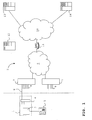
- FIG. 1 depicts a schematic illustration of a communication network for providing IP telephony services to a residential network access device according to an embodiment of the invention;
- FIG. 2 displays a schematic illustration of an adaptor of a residential network access device;
- FIG. 3 shows a first example of a communication diagram for performing a method for service preparation of a residential network access device over the communication network of FIG. 1 according to an embodiment of the invention, and
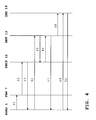
- FIG. 4 shows a second example of a communication diagram for performing a method for service preparation of a residential network access device over the communication network of FIG. 1 according to an embodiment of the invention.
- In FIG. 1, a residential
network access device 1, hereinafter also referred to as RNAD, is illustrated that is connected to acommunication network 2. The RNAD 1 comprises anadaptor 3 and a fibre network terminator 4 and is capable of being connected to a conventional (copper) wiredtelephone 5. - It should be noted that the
adaptor 3 and the fibre network terminator 4 are not necessarily integrated in a single device. In that case, the fibre network terminator 4 may provide RJ45 connections for connection of theadaptor 3. - It should further be appreciated that, although the presently described embodiment is limited to a fibre network connection, the described method, procedures and system are equally well applicable to copper wired connection, e.g. for xDSL connections with IP applications over Ethernet.
- The
adaptor 3, when properly configured according to the below described method, is capable of providing an IP telephony network service (VoIP) for theconventional telephone 5 over thecommunication network 2. - The fibre network terminator 4 provides Ethernet access for the customer of the
RNAD 1. In the present embodiment, the functionality of the fibre network terminator 4 is limited to providing access on Ethernet level via one or more virtual local area networks (VLANs). The fibre network terminator 4 comprises further connections for receiving other services over the communication network that will not be described further. - The RNAD 1 is communicatively connected by a
fibre 6 to thecommunication network 2 by a fibreaccess node device 7. The fibreaccess node device 7 comprises a fibre access card withinputs 8 for further fibres of further RNADs (not shown). The fibreaccess node device 7 may be capable of receiving fibres of several hundreds ofRNADs 1. In the fibre access node, the VLANs of theRNADs 1 are mapped on a VLAN connection to anIP edge router 11 for IP routing with provisioning devices as will be further described below. - The
communication network 2 comprises an Ethernet part 9 and anIP part 10, said parts being separated by theedge router 11. - The
communication network 2 further comprises a plurality of provisioning devices 12-14. - In particular, the
provisioning device 12 may be a server, connected to therouter 11, that is capable of assigning IP addresses to devices over thecommunication network 2, such as a Dynamic Host Configuration Protocol (DHCP) server. DHCP automates the assignment of IP addresses. -
Provisioning device 13 is a management server taking care of the actual preparation of theRNAD 1 for receiving the IP telephony service over thecommunication network 2. -
Provisioning device 14 is an IP multimedia subsystem (IMS) providing the IP telephony service by voice emulation after preparation of theRNAD 1 for receiving this service. IMS uses open standard IP protocols, defined by the IEFT, and is capable of providing IP based services, such as VoIP. TheIMS 14 employs a telephony application server (not shown individually) that uses the Session Initiation Protocol (SIP) for call session control of theRNAD 1. SIP is an application layer signaling peer-to-peer protocol for creating, modifying and terminating sessions, such as IP telephone calls. SIP is specified in RFC 3261 of the IEFT SIP Working Group. It should be appreciated, however, that other signaling protocols, such as H.248, may be used. - It will be evident for the skilled person that the system illustrated in FIG. 1 may contain further devices or systems for executing further functions, including, but not limited to, couplings for the
IMS 14 to an existing conventional PSTN network (bridge-to-voice), systems for billing, maintenance, service etc. and a Session Border Controller (SBC). A SBC is a device used in some IP telephony networks for exerting control over the signaling and media streams involved in setting up, conducting, and tearing down calls. SBCs are put into the signaling and/or media path between a calling and a called party and may split a SIP signalling stream and a RTP media stream. - A customer desiring to receive IP telephony network services for a service provider may obtain a
RNAD 1 or anadaptor 3 as shown schematically in FIG. 2. As mentioned above, the dwelling of the customer may already contain a fibre network terminator 4, such that only anadaptor 3 is required for receiving the IP telephony service. Theadaptor 3 comprises afirst connection 20 for theconventional telephone 5 and asecond connection 21 for a fibre connection to the fibre network terminator 4 and further to the networkaccess node device 7 over thefibre 6. Theadaptor 3 further comprises aprocessor 22 and amemory 23. Theprocessor 22 is arranged for converting SIP controlled IP telephony signals from theIMS 14 into conventional POTS signals for thetelephone 5 by emulation of a POTS service and vice versa. Thememory 23 stores a device identifier, such as a unique media access control (MAC) address. Furthermore, the memory may store further data obtained in the method described below. Thememory 23 may be flash memory capable of storing configuration data. For such anRNAD 1, power failure does not directly require anew service preparation of theRNAD 1. - FIG. 3 shows a first example of a communication diagram for performing a method for service preparation of the
RNAD 1 over thecommunication network 2 of FIG. 1 according to an embodiment of the invention. - The customer that obtained the
adaptor 3 of FIG. 2 plugssecond connection 21 into the appropriate connection of the fibre network terminator 4. A DHCP request, using DHCP option 82 and indicated bystep 31 in FIG. 3, is then automatically triggered and transmitted to the fibreaccess node device 7. Therequest 31 may include the MAC identifier of theRNAD 1 and other credentials of theRNAD 1, such as a serial number. The request may be a broadcast request toDHCP servers 12 listening in thecommunication network 2 for this request in order to provide an IP address to theRNAD 1. Alternatively, theRNAD 1 may have aspecific URL 12 of aDHCP server 12 stored in itsmemory 23. - The fibre
access node device 7 analyses the line ID, indicating the port used by the physical line, i.e. thefibre 6, over which the DHCP request is received. This line ID is stored in the fibreaccess node device 7 together with the MAC address of theRNAD 1 via Ethernet learning. The line ID is not known at theRNAD 1 and thus is only available in thecommunication network 2. The MAC address is unique within the fibreaccess node device 7. The fibreaccess node device 7 then forwards the DHCP request instep 32 to theDHCP server 12. - In the embodiment of FIG. 3, the
DHCP server 12 comprises a configuration table of IP addresses corresponding to the line ID's in the various fibreaccess node devices 7. TheDHCP server 12 selects the IP address corresponding to the line ID offibre 6 and returns the IP address instep 33 to theRNAD 1. In this step the IP source address is assigned to theRNAD 1. Therouter 11 intercepts and stores the MAC address ofRNAD 1 in, combination with the selected IP address. Furthermore, anetwork address URL 13 of themanagement server 13 is returned to theRNAD 1. - In
step 34, theDHCP server 12 communicates the assigned IP source address to themanagement server 13. The assigned IP address may also be communicated to IMS 14 (not shown), if the IP address is used for authentication purposes inIMS 14. - In
step 35, a request containing the MAC address ofRNAD 1 is received at themanagement server 13 withURL 13 from theRNAD 1 for network service preparation. Themanagement server 13 is already aware of the IP source address of theRNAD 1, since this address was obtained instep 34 from theDHCP server 12. - In
response step 36, themanagement server 13 transmits voice emulation software code portions to the assigned IP address ofRNAD 1 for loading in the firmware of theRNAD 1. The software code portions are required for receiving the IP telephony network service. Apart from the software for configuring theRNAD 1, theRNAD 1 receives customer specific credentials from themanagement server 13, including a public ID (e.g. a E.164 telephone number and a host domain), a private ID (a customer number to be used, e.g., for billing purposes) and possible other information such as a digit map. The public ID may e.g. be retrieved from a table storing relations between assigned IP source addresses for theRNAD 1 with a corresponding E.164 telephone number. Also, theRNAD 1 receives a further network address,URL 14, of theIMS server 14. In the exchange of information between theRNAD 1 and themanagement server 13, a trusted connection may be arranged between theRNAD 1 and themanagement server 13 on the basis of an encrypted identifier. - In
step 37, themanagement server 13 communicates the assigned credentials, e.g. public ID and private ID, to theIMS 14. This step may be omitted if themanagement server 13 has received the IP source address of theRNAD 1 from theDHCP server 12. - In
registration step 38, theRNAD 1 contacts theIMS 14 viaURL 14 for the first time by transmitting the received credentials, such as the public ID and private ID, to theIMS 14. A customer specific service profile is established for theRNAD 1 with the line identifier of thefibre 6. TheIMS 14 may act either on the basis of the credentials if these are trusted or also check the IP source address of theRNAD 1 if the IP source address has been provided toIMS 14. - In
registration confirmation step 39, theRNAD 1 is signalled that the IP telephony service is ready. From this moment on, the customer may initiate or receive IP telephone calls with hisconventional telephone 5. - In the exchange of information of
steps RNAD 1 and theIMS 14. - In the method depicted in FIG. 3, the IP source address for the
RNAD 1 is a permanent address. FIG. 4 shows a second example of a communication diagram for performing a method for service preparation of theRNAD 1 over thecommunication network 2 of FIG. 1 according to an embodiment of the invention. In this method theDHCP server 12 dynamically assigns IP source addresses to theRNADs 1. Such an embodiment may prove to be advantageous with regard to the scalability of the system, since theDHCP server 12 no longer contains a configuration table with a reserved IP address for each line identifier. - Again, the customer that obtained the
adaptor 3 of FIG. 2 simply connects thesecond connection 21 into the appropriate connection of his dwelling. A DHCP broadcast request, using DHCP option 82 and indicated bystep 41 in FIG. 4, is then automatically triggered and transmitted to the fibreaccess node device 7. Again, therequest 31 may include the MAC identifier of theRNAD 1 and other credentials of theRNAD 1, such as a serial number. The fibreaccess node device 7 analyses the line ID, indicating the port used by the physical line, i.e. thefibre 6, over which the request is received. This line ID is stored in thefibre access node 7 together with the MAC address of theRNAD 1 via Ethernet learning and is not available to theRNAD 1. The MAC address is unique within thefibre access node 7. - The
fibre access node 7 forwards the DHCP request instep 42 to theDHCP server 12. - The
DHCP server 12 now assigns a dynamic IP source address to theRNAD 1 instep 43 as opposed to the method as described with reference to FIG. 3. TheDHCP server 12 stores the assigned IP address and the associated line ID. Therouter 11 intercepts and stores the MAC address ofRNAD 1 in combination with the assigned IP address. Furthermore, anetwork address URL 13 of themanagement server 13 is returned instep 43. - In
step 44, a request containing the MAC address ofRNAD 1 is received at themanagement server 13 from theRNAD 1 for network service preparation. - In
step 45, themanagement server 13 transmits a request toDHCP server 12 to check whetherDHCP server 12 assigned an IP source address toRNAD 1 instep 43. Instep 46, the assignment of such an IP source address is confirmed by theDHCP server 12 to themanagement server 13. - In
response step 47, themanagement server 13 transmits voice emulation software code portions to the dynamically assigned IP address ofRNAD 1 for loading in the firmware of theRNAD 1. The software code portions are required for receiving the IP telephony network service. Apart from the software for configuring theRNAD 1, theRNAD 1 receives customer specific credentials from themanagement server 13, including a public ID (e.g. a E.164 telephone number and a host domain), a private ID (a customer number to be used, e.g. for billing purposes) and possible other information such as a digit map. Also, theRNAD 1 receives a further network address,URL 14, of theIMS server 14. In the exchange of information between theRNAD 1 and themanagement server 13, a trusted connection may be obtained on the basis of an encrypted identifier. - In
step 48, themanagement server 13 communicates the assigned credentials, e.g. the public ID and private ID, to theIMS 14. - In
registration step 49, theRNAD 1 contacts theIMS 14 for the first time by transmitting the public ID and private ID, to theIMS 14. A customer specific service profile is established for theRNAD 1 with the line identifier of thefibre 6. - In
registration confirmation step 50, theRNAD 1 is signalled that the IP telephony service is ready. From this moment on, the customer may initiate or receive IP telephone calls with hisconventional telephone 5. - In the exchange of information of
steps RNAD 1 and theIMS 14. - It should be appreciated from the above described methods that the action for the customer is limited to plugging the
RNAD 1, or theadaptor 3 if a fibre network terminator 4 is already installed, in the appropriate connection. This action corresponds to connecting a POTS device to a conventional telecommunication network. The further preparation of theRNAD 1 to a service ready state is fully automatic. - The part of the
communication network 2 ranging from the fibreaccess node device 7 to the provisioning devices 12-14 and further is what is referred to as a 'trusted' communication network. In other words, source identifiers of traffic, such as the line ID, are reliable in the trusted part of communication networks. On the other hand, source identifiers from theRNAD 1 can be manipulated on various levels (physically, e.g. by reconnecting fibres to other ports or on another level, e.g. spoofing of the MAC address of anRNAD 1 by another user) and is 'untrusted'. - Both the line ID of the
RNAD 1 and the IP address assigned to theRNAD 1 are trusted parameters, since these are assigned by the fibreaccess node device 7 and theDHCP server 12, respectively, which are in the trusted part of thecommunication network 2. The MAC address of theRNAD 1, which may be spoofed and is, therefore, untrusted, has a bridging function between these trusted parameters. - If one desires to prevent nomadic use of the
RNAD 1, i.e. use of theRNAD 1 from different physical lines that is noticed by the service provider, measures may be taken if the above described method is applied. These measures may prevent malicious use as well. - First, the fibre
access node device 7 has stored a line identifier and a MAC address of theRNAD 1 insteps fibre access node 7 receives the same MAC address over another physical line, access is denied for the latter received MAC address since it does not correspond to the line ID - MAC address pair stored in the fibreaccess node device 7. Retrieving the MAC address at the fibreaccess node device 7 may be performed by Ethernet learning. Blocking access on the basis of Ethernet learning requires frequent (5-15 minutes) transactions between theRNAD 1 and the fibreaccess node device 7. The number of MAC addresses for a particular VLAN may be restricted to e.g. two. - Second, the
edge router 11 has stored a pair relating the assigned IP address of theRNAD 1 and the MAC address instep RNAD 1 requesting IP telephony service via anotherfibre access node 7 is denied access at theedge router 11 if the received source IP address and MAC address do not correspond to the pair stored at theedge router 11. - Thus, both the
fibre access node 7 and IP edge router perform filtering or screening functions to avoid nomadic use of theRNAD 1.
Claims (26)
- A method of service preparation of a residential network access device from one or more remote provisioning devices to prepare said residential network access device to receive a network service over a communications network, said method comprising the steps of:- receiving a line identifier indicating a physical line used by said residential network access device to connect to said communication network;- transmitting an IP address from said one or more provisioning devices to said residential network access device for which said line identifier has been received, said IP address being a source address for said residential network access device, and- transmitting software code portions to said IP address of said residential network access device, said software code portions being required for receiving said network service.
- The method according to claim 1, further comprising the steps of:- transmitting a further IP address to said residential network access device for which said line identifier has been received;- receiving on said further IP address a request for transmitting said software code portions.
- The method according to claim 1, further comprising the step of receiving a MAC address of said residential network access device.
- The method according to one or more of the precedeng claims, wherein said communication network comprises an untrusted part and a trusted part, said untrusted part comprising said residential network access device, said communication network further comprising a network access node device capable of establishing a communicative connection between a plurality of said residential network access devices and said one or more remote provisioning devices, wherein said network access node device and said remote provisioning devices are part of said trusted part of said communication network, wherein said method further comprises the steps of:- receiving a device identifier of said residential network access device, preferably a MAC address, at said network access node device;- retrieving said line identifier by which said residential network access device connects to said network access node device, and- transmitting said line identifier to one or more of said provisioning devices.
- The method according to claim 4, further comprising the steps of:- storing said device identifier to obtain a device identifier-line identifier pair, such that said pair is available for said network access node device, and- granting or denying access to said network service by evaluating a request for said network service on the basis of said device identifier - line identifier pair.
- The method according to claim 4 or 5, wherein said communication network comprises a network router and wherein said method further comprises the steps of:- storing said device identifier to obtain a device identifier-IP address pair, such that said pair is available for said network router, and- granting or denying access to said network service by evaluating a request for said network service on the basis of said device identifier - IP address pair.
- The method according to one or more of the preceding claims, wherein said provisioning devices comprise an IP address assigning server, such as a DHCP server, for transmitting said IP address to said residential network access device and a management server, said management server transmitting said software code portions to said IP address, further comprising the step of exchanging said IP address between said IP address assigning server and said management server.
- The method according to one or more of the preceding claims, further comprising the step of transmitting one or more service credentials to said IP address of said residential network access device.
- The method according to claim 8, further comprising the step of receiving said credentials from said residential network access device at a provisioning device delivering said network service
- The method according to claim 9, further comprising at least one of the following steps:- linking said credentials to a service profile of a user of said residential network access device;- granting access to said network service by evaluating a request for said network service on the basis of said credentials.
- The method according to one or more of the preceding claims, wherein said network service is a VoIP telephony service.
- The method according to one or more of the preceding claims, wherein at least one of said provisioning devices controls said residential network access device using the session initiation protocol (SIP).
- A system for service preparation of a residential network access device to receive a network service over a communications network, said system comprising one or more remote provisioning devices and a network access node device arranged for establishing a communicative connection between a plurality of said residential network access devices and said one or more remote provisioning devices, wherein said provisioning devices are arranged for:- receiving a line identifier from said network access node device indicating a physical line used by said residential network access device to connect to said communication network;- transmitting an IP address from said one or more provisioning devices to said residential network access device for which said line identifier has been received, said IP address being a source address for said residential network access device, and- transmitting software code portions to said IP address of said residential network access device, said software code portions being required for receiving said network service.
- The system according to claim 13, wherein said network access node device is further arranged for retrieving a MAC address of said residential network access device.
- The system according to claims 13 or 14, wherein said communication network comprises a router and wherein said communication network is an Ethernet network between said residential network access device and said router and an IP network between said router and said provisioning devices.
- The system according to claim 15, wherein said network access node device is part of said Ethernet network and communication between said residential network access device and said network access node device and said network access node device and said router is established over virtual LANs.
- The system according to one or more of the claims 13-16, wherein said communication network between said residential network access device and said network access node device is a fibre network.
- The system according to one or more of the claims 13-17, wherein said network access node device is arranged for- receiving a device identifier of said residential network access device, preferably a MAC address, at said network access node device;- retrieving said line identifier by which said residential network access device connects to said network access node device, and- transmitting said line identifier to one or more of said provisioning devices.
- The system according to claim 18, wherein said network access node device is further arranged for:- storing said device identifier to obtain a device identifier-line identifier pair, such that said pair is available for said network access node device, and- granting or denying access to said network service by evaluating a request for said network service on the basis of said device identifier - line identifier pair.
- The system according to claim 18 or 19, wherein said communication network comprises a network router and wherein said network router is arranged for:- storing said device identifier to obtain a device identifier-IP address pair, such that said pair is available for said edge router, and- granting or denying access to said network service by evaluating a request for said network service on the basis of said device identifier-IP address pair.
- The system according to one or more of the claims 13-20, wherein said network service is a VoIP telephony service.
- The system according to one or more of the claims 13-21, wherein at least one of said provisioning devices is arranged for controlling said residential network access device using the session initiation protocol (SIP).
- A collection of computer programs comprising software code portions capable of executing, when run on a computer, the steps of the method as defined in one or more of the claims 1-12, wherein a variety of network devices of the system of claims 13-22, including said provisioning devices, said network access node device and said network router, each run a computer program of said collection.
- A residential network access device arranged for use in a system according to one or more of the claims 13-22, storing a MAC address and arranged for transmitting a DHCP broadcast request.
- The residential network access device according to claim 24, comprising a connection for a wired telephone and a fibre connection for connection to the communication network.
- The residential network access device according to claim 24 or 25, arranged for being controlled by a session initiation protocol.
Priority Applications (8)
| Application Number | Priority Date | Filing Date | Title |
|---|---|---|---|
| ES06021448T ES2342784T3 (en) | 2006-10-12 | 2006-10-12 | METHOD AND SYSTEM FOR THE PREPARATION OF SERVICE OF A RESIDENTIAL NETWORK ACCESS DEVICE. |
| EP06021448A EP1912411B1 (en) | 2006-10-12 | 2006-10-12 | Method and system for service preparation of a residential network access device |
| DE602006013324T DE602006013324D1 (en) | 2006-10-12 | 2006-10-12 | Method and system for preparing services from an access device in a domestic network |
| AT06021448T ATE463121T1 (en) | 2006-10-12 | 2006-10-12 | METHOD AND SYSTEM FOR PREPARING SERVICES FROM AN ACCESS DEVICE IN A HOME NETWORK |
| PCT/EP2007/008466 WO2008043442A2 (en) | 2006-10-12 | 2007-09-28 | Method and system for service preparation of a residential network access device |
| US12/445,121 US7940782B2 (en) | 2006-10-12 | 2007-09-28 | Method and system for service preparation of a residential network access device |
| US13/075,398 US9769009B2 (en) | 2006-10-12 | 2011-03-30 | Method and system for service preparation of a residential network access device |
| US15/601,343 US20170272302A1 (en) | 2006-10-12 | 2017-05-22 | Method and system for service preparation of a residential network access device |
Applications Claiming Priority (1)
| Application Number | Priority Date | Filing Date | Title |
|---|---|---|---|
| EP06021448A EP1912411B1 (en) | 2006-10-12 | 2006-10-12 | Method and system for service preparation of a residential network access device |
Publications (2)
| Publication Number | Publication Date |
|---|---|
| EP1912411A1 true EP1912411A1 (en) | 2008-04-16 |
| EP1912411B1 EP1912411B1 (en) | 2010-03-31 |
Family
ID=37875505
Family Applications (1)
| Application Number | Title | Priority Date | Filing Date |
|---|---|---|---|
| EP06021448A Not-in-force EP1912411B1 (en) | 2006-10-12 | 2006-10-12 | Method and system for service preparation of a residential network access device |
Country Status (6)
| Country | Link |
|---|---|
| US (3) | US7940782B2 (en) |
| EP (1) | EP1912411B1 (en) |
| AT (1) | ATE463121T1 (en) |
| DE (1) | DE602006013324D1 (en) |
| ES (1) | ES2342784T3 (en) |
| WO (1) | WO2008043442A2 (en) |
Cited By (2)
| Publication number | Priority date | Publication date | Assignee | Title |
|---|---|---|---|---|
| EP2328355A1 (en) | 2009-11-27 | 2011-06-01 | Koninklijke KPN N.V. | Automated service migration |
| EP2747360A1 (en) | 2012-12-20 | 2014-06-25 | Koninklijke KPN N.V. | Provisioning a user device in a network subsystem |
Families Citing this family (3)
| Publication number | Priority date | Publication date | Assignee | Title |
|---|---|---|---|---|
| US8918531B2 (en) | 2009-05-07 | 2014-12-23 | Cisco Technology, Inc. | Automated network device provisioning using dynamic host configuration protocol |
| US8879419B2 (en) * | 2009-07-28 | 2014-11-04 | Centurylink Intellectual Property Llc | System and method for registering an IP telephone |
| TWI521969B (en) * | 2013-07-01 | 2016-02-11 | 明基電通股份有限公司 | Matching method and data sharing method for network access apparatus |
Citations (4)
| Publication number | Priority date | Publication date | Assignee | Title |
|---|---|---|---|---|
| US20020162029A1 (en) | 2001-04-25 | 2002-10-31 | Allen Keith Joseph | Method and system for broadband network access |
| EP1271849A1 (en) | 2001-06-14 | 2003-01-02 | Alcatel | Processor system, access server system, method and computer program product |
| US20050149748A1 (en) | 2003-12-19 | 2005-07-07 | Spry Andrew J. | Method and apparatus for identifying IPsec security policy in iSCSI |
| US20060079280A1 (en) | 2004-09-13 | 2006-04-13 | Laperch Richard C | Personal wireless gateway and method for implementing the same |
Family Cites Families (19)
| Publication number | Priority date | Publication date | Assignee | Title |
|---|---|---|---|---|
| US6292794B1 (en) * | 1998-10-22 | 2001-09-18 | Libera, Inc. | Method of integrating text retrieval to enhance software stem searching |
| US6400730B1 (en) * | 1999-03-10 | 2002-06-04 | Nishan Systems, Inc. | Method and apparatus for transferring data between IP network devices and SCSI and fibre channel devices over an IP network |
| EP1293790B1 (en) * | 2001-09-18 | 2006-12-20 | STMicroelectronics Limited | Scan test apparatus using oversampling for synchronisation |
| US7274684B2 (en) * | 2001-10-10 | 2007-09-25 | Bruce Fitzgerald Young | Method and system for implementing and managing a multimedia access network device |
| US20030105881A1 (en) * | 2001-12-03 | 2003-06-05 | Symons Julie Anna | Method for detecting and preventing intrusion in a virtually-wired switching fabric |
| US7480724B2 (en) * | 2002-09-25 | 2009-01-20 | At&T Intellectual Property I, L.P. | API tool-set for providing services through a residential communication gateway |
| CN100472485C (en) * | 2003-04-25 | 2009-03-25 | 松下电器产业株式会社 | Server and processing method of server |
| US7516487B1 (en) * | 2003-05-21 | 2009-04-07 | Foundry Networks, Inc. | System and method for source IP anti-spoofing security |
| US7899929B1 (en) * | 2003-06-05 | 2011-03-01 | Juniper Networks, Inc. | Systems and methods to perform hybrid switching and routing functions |
| JP3803669B2 (en) * | 2003-11-07 | 2006-08-02 | Necアクセステクニカ株式会社 | Network connection system and network connection method |
| US7673021B2 (en) * | 2004-02-12 | 2010-03-02 | Cisco Technology, Inc. | Automated provisioning of phones in packet voice networks |
| JP4176655B2 (en) * | 2004-02-24 | 2008-11-05 | 株式会社エヌ・ティ・ティ・ドコモ | Address dynamic allocation system, relay apparatus, and address dynamic allocation method |
| US7623518B2 (en) * | 2004-04-08 | 2009-11-24 | Hewlett-Packard Development Company, L.P. | Dynamic access control lists |
| US7422152B2 (en) * | 2004-05-13 | 2008-09-09 | Cisco Technology, Inc. | Methods and devices for providing scalable RFID networks |
| CA2605304C (en) * | 2005-03-29 | 2011-10-04 | Research In Motion Limited | Methods and apparatus for use in establishing session initiation protocol communications for virtual private networking |
| US8079062B2 (en) * | 2005-05-16 | 2011-12-13 | Cisco Technology, Inc. | Method and system using presence information to manage network access |
| US8094663B2 (en) * | 2005-05-31 | 2012-01-10 | Cisco Technology, Inc. | System and method for authentication of SP ethernet aggregation networks |
| US8238352B2 (en) * | 2005-09-02 | 2012-08-07 | Cisco Technology, Inc. | System and apparatus for rogue VoIP phone detection and managing VoIP phone mobility |
| US8553678B2 (en) * | 2005-10-04 | 2013-10-08 | Cisco Technology, Inc. | Distributed codec for packet-based communications |
-
2006
- 2006-10-12 EP EP06021448A patent/EP1912411B1/en not_active Not-in-force
- 2006-10-12 ES ES06021448T patent/ES2342784T3/en active Active
- 2006-10-12 DE DE602006013324T patent/DE602006013324D1/en active Active
- 2006-10-12 AT AT06021448T patent/ATE463121T1/en not_active IP Right Cessation
-
2007
- 2007-09-28 WO PCT/EP2007/008466 patent/WO2008043442A2/en not_active Ceased
- 2007-09-28 US US12/445,121 patent/US7940782B2/en active Active
-
2011
- 2011-03-30 US US13/075,398 patent/US9769009B2/en active Active
-
2017
- 2017-05-22 US US15/601,343 patent/US20170272302A1/en not_active Abandoned
Patent Citations (4)
| Publication number | Priority date | Publication date | Assignee | Title |
|---|---|---|---|---|
| US20020162029A1 (en) | 2001-04-25 | 2002-10-31 | Allen Keith Joseph | Method and system for broadband network access |
| EP1271849A1 (en) | 2001-06-14 | 2003-01-02 | Alcatel | Processor system, access server system, method and computer program product |
| US20050149748A1 (en) | 2003-12-19 | 2005-07-07 | Spry Andrew J. | Method and apparatus for identifying IPsec security policy in iSCSI |
| US20060079280A1 (en) | 2004-09-13 | 2006-04-13 | Laperch Richard C | Personal wireless gateway and method for implementing the same |
Non-Patent Citations (2)
| Title |
|---|
| GASPARRO D M ET AL., DATACOMM., vol. 25, no. 12, 1 September 1996 (1996-09-01) |
| GASPARRO D M: "IP ADDRESSING: PLAN OR PAY", DATA COMMUNICATIONS, MCGRAW HILL. NEW YORK, US, vol. 25, no. 12, 1 September 1996 (1996-09-01), pages 59 - 62,64,66, XP000626549, ISSN: 0363-6399 * |
Cited By (2)
| Publication number | Priority date | Publication date | Assignee | Title |
|---|---|---|---|---|
| EP2328355A1 (en) | 2009-11-27 | 2011-06-01 | Koninklijke KPN N.V. | Automated service migration |
| EP2747360A1 (en) | 2012-12-20 | 2014-06-25 | Koninklijke KPN N.V. | Provisioning a user device in a network subsystem |
Also Published As
| Publication number | Publication date |
|---|---|
| US9769009B2 (en) | 2017-09-19 |
| US20170272302A1 (en) | 2017-09-21 |
| ATE463121T1 (en) | 2010-04-15 |
| US20110176548A1 (en) | 2011-07-21 |
| DE602006013324D1 (en) | 2010-05-12 |
| WO2008043442A3 (en) | 2008-07-10 |
| ES2342784T3 (en) | 2010-07-14 |
| WO2008043442A2 (en) | 2008-04-17 |
| US20100085958A1 (en) | 2010-04-08 |
| EP1912411B1 (en) | 2010-03-31 |
| US7940782B2 (en) | 2011-05-10 |
Similar Documents
| Publication | Publication Date | Title |
|---|---|---|
| US6400707B1 (en) | Real time firewall security | |
| US20020010865A1 (en) | Method and apparatus for remote office access management | |
| US7773532B2 (en) | Method for enabling communication between two network nodes via a network address translation device (NAT) | |
| EP1751923B1 (en) | Multimedia access device and system employing the same | |
| CN103039038B (en) | Method and system for efficient use of a telecommunications network and connections between the telecommunications network and customer premises equipment | |
| US20170272302A1 (en) | Method and system for service preparation of a residential network access device | |
| US20080225749A1 (en) | Auto-configuration of a network device | |
| CN101309284B (en) | Remote access communication method, apparatus and system | |
| US20020159442A1 (en) | Method of indicating the origin of a mobile user in a data network | |
| EP1898594A2 (en) | A method for providing broadband communication services | |
| US7342920B2 (en) | Voice over internet protocol (VoIP) telephone apparatus and communications systems for carrying VoIP traffic | |
| CN1332542C (en) | VoIP wireless telephone system and method utilizing wireless LAN | |
| CN106210034A (en) | A kind of intelligent terminal's management-control method based on IMS enterprise network and system | |
| US6594350B2 (en) | Dial on demand communication | |
| CN103069750B (en) | The method and system of the connection for being efficiently used between communication network and this communication network and customer rs premise equipment | |
| CN108429773B (en) | Authentication method and authentication system | |
| CA2454408C (en) | Subscriber station | |
| CN102075939B (en) | Method, equipment and system for preventing service embezzlement | |
| CN101170502B (en) | A method and system for realizing mutual access between stacking members | |
| WO2003043292A2 (en) | Method for allocating a non-data device to a voice vlan | |
| CN104982064B (en) | Managed Handoff Process | |
| WO2005064851A1 (en) | Remotely managed subscriber station | |
| CN101238704B (en) | Method and system for supporting shared local trunking | |
| JP4796924B2 (en) | Button phone system | |
| US7027581B1 (en) | Method for exchanging signaling messages in two phases |
Legal Events
| Date | Code | Title | Description |
|---|---|---|---|
| PUAI | Public reference made under article 153(3) epc to a published international application that has entered the european phase |
Free format text: ORIGINAL CODE: 0009012 |
|
| AK | Designated contracting states |
Kind code of ref document: A1 Designated state(s): AT BE BG CH CY CZ DE DK EE ES FI FR GB GR HU IE IS IT LI LT LU LV MC NL PL PT RO SE SI SK TR |
|
| AX | Request for extension of the european patent |
Extension state: AL BA HR MK RS |
|
| 17P | Request for examination filed |
Effective date: 20081016 |
|
| 17Q | First examination report despatched |
Effective date: 20081113 |
|
| AKX | Designation fees paid |
Designated state(s): AT BE BG CH CY CZ DE DK EE ES FI FR GB GR HU IE IS IT LI LT LU LV MC NL PL PT RO SE SI SK TR |
|
| GRAP | Despatch of communication of intention to grant a patent |
Free format text: ORIGINAL CODE: EPIDOSNIGR1 |
|
| GRAS | Grant fee paid |
Free format text: ORIGINAL CODE: EPIDOSNIGR3 |
|
| GRAA | (expected) grant |
Free format text: ORIGINAL CODE: 0009210 |
|
| AK | Designated contracting states |
Kind code of ref document: B1 Designated state(s): AT BE BG CH CY CZ DE DK EE ES FI FR GB GR HU IE IS IT LI LT LU LV MC NL PL PT RO SE SI SK TR |
|
| REG | Reference to a national code |
Ref country code: CH Ref legal event code: EP Ref country code: GB Ref legal event code: FG4D |
|
| REG | Reference to a national code |
Ref country code: IE Ref legal event code: FG4D |
|
| REF | Corresponds to: |
Ref document number: 602006013324 Country of ref document: DE Date of ref document: 20100512 Kind code of ref document: P |
|
| REG | Reference to a national code |
Ref country code: DE Ref legal event code: R096 Ref document number: 602006013324 Country of ref document: DE Effective date: 20100512 |
|
| REG | Reference to a national code |
Ref country code: NL Ref legal event code: T3 |
|
| REG | Reference to a national code |
Ref country code: ES Ref legal event code: FG2A Ref document number: 2342784 Country of ref document: ES Kind code of ref document: T3 |
|
| PG25 | Lapsed in a contracting state [announced via postgrant information from national office to epo] |
Ref country code: LT Free format text: LAPSE BECAUSE OF FAILURE TO SUBMIT A TRANSLATION OF THE DESCRIPTION OR TO PAY THE FEE WITHIN THE PRESCRIBED TIME-LIMIT Effective date: 20100331 |
|
| LTIE | Lt: invalidation of european patent or patent extension |
Effective date: 20100331 |
|
| PG25 | Lapsed in a contracting state [announced via postgrant information from national office to epo] |
Ref country code: LV Free format text: LAPSE BECAUSE OF FAILURE TO SUBMIT A TRANSLATION OF THE DESCRIPTION OR TO PAY THE FEE WITHIN THE PRESCRIBED TIME-LIMIT Effective date: 20100331 Ref country code: PL Free format text: LAPSE BECAUSE OF FAILURE TO SUBMIT A TRANSLATION OF THE DESCRIPTION OR TO PAY THE FEE WITHIN THE PRESCRIBED TIME-LIMIT Effective date: 20100331 Ref country code: SI Free format text: LAPSE BECAUSE OF FAILURE TO SUBMIT A TRANSLATION OF THE DESCRIPTION OR TO PAY THE FEE WITHIN THE PRESCRIBED TIME-LIMIT Effective date: 20100331 Ref country code: AT Free format text: LAPSE BECAUSE OF FAILURE TO SUBMIT A TRANSLATION OF THE DESCRIPTION OR TO PAY THE FEE WITHIN THE PRESCRIBED TIME-LIMIT Effective date: 20100331 Ref country code: FI Free format text: LAPSE BECAUSE OF FAILURE TO SUBMIT A TRANSLATION OF THE DESCRIPTION OR TO PAY THE FEE WITHIN THE PRESCRIBED TIME-LIMIT Effective date: 20100331 |
|
| PG25 | Lapsed in a contracting state [announced via postgrant information from national office to epo] |
Ref country code: SE Free format text: LAPSE BECAUSE OF FAILURE TO SUBMIT A TRANSLATION OF THE DESCRIPTION OR TO PAY THE FEE WITHIN THE PRESCRIBED TIME-LIMIT Effective date: 20100331 Ref country code: RO Free format text: LAPSE BECAUSE OF FAILURE TO SUBMIT A TRANSLATION OF THE DESCRIPTION OR TO PAY THE FEE WITHIN THE PRESCRIBED TIME-LIMIT Effective date: 20100331 Ref country code: CY Free format text: LAPSE BECAUSE OF FAILURE TO SUBMIT A TRANSLATION OF THE DESCRIPTION OR TO PAY THE FEE WITHIN THE PRESCRIBED TIME-LIMIT Effective date: 20100331 Ref country code: BE Free format text: LAPSE BECAUSE OF FAILURE TO SUBMIT A TRANSLATION OF THE DESCRIPTION OR TO PAY THE FEE WITHIN THE PRESCRIBED TIME-LIMIT Effective date: 20100331 Ref country code: EE Free format text: LAPSE BECAUSE OF FAILURE TO SUBMIT A TRANSLATION OF THE DESCRIPTION OR TO PAY THE FEE WITHIN THE PRESCRIBED TIME-LIMIT Effective date: 20100331 |
|
| PG25 | Lapsed in a contracting state [announced via postgrant information from national office to epo] |
Ref country code: CZ Free format text: LAPSE BECAUSE OF FAILURE TO SUBMIT A TRANSLATION OF THE DESCRIPTION OR TO PAY THE FEE WITHIN THE PRESCRIBED TIME-LIMIT Effective date: 20100331 Ref country code: IS Free format text: LAPSE BECAUSE OF FAILURE TO SUBMIT A TRANSLATION OF THE DESCRIPTION OR TO PAY THE FEE WITHIN THE PRESCRIBED TIME-LIMIT Effective date: 20100731 Ref country code: SK Free format text: LAPSE BECAUSE OF FAILURE TO SUBMIT A TRANSLATION OF THE DESCRIPTION OR TO PAY THE FEE WITHIN THE PRESCRIBED TIME-LIMIT Effective date: 20100331 |
|
| PG25 | Lapsed in a contracting state [announced via postgrant information from national office to epo] |
Ref country code: PT Free format text: LAPSE BECAUSE OF FAILURE TO SUBMIT A TRANSLATION OF THE DESCRIPTION OR TO PAY THE FEE WITHIN THE PRESCRIBED TIME-LIMIT Effective date: 20100802 Ref country code: DK Free format text: LAPSE BECAUSE OF FAILURE TO SUBMIT A TRANSLATION OF THE DESCRIPTION OR TO PAY THE FEE WITHIN THE PRESCRIBED TIME-LIMIT Effective date: 20100331 |
|
| PLBE | No opposition filed within time limit |
Free format text: ORIGINAL CODE: 0009261 |
|
| STAA | Information on the status of an ep patent application or granted ep patent |
Free format text: STATUS: NO OPPOSITION FILED WITHIN TIME LIMIT |
|
| 26N | No opposition filed |
Effective date: 20110104 |
|
| REG | Reference to a national code |
Ref country code: DE Ref legal event code: R097 Ref document number: 602006013324 Country of ref document: DE Effective date: 20110104 |
|
| PG25 | Lapsed in a contracting state [announced via postgrant information from national office to epo] |
Ref country code: MC Free format text: LAPSE BECAUSE OF NON-PAYMENT OF DUE FEES Effective date: 20101031 |
|
| REG | Reference to a national code |
Ref country code: CH Ref legal event code: PL |
|
| PG25 | Lapsed in a contracting state [announced via postgrant information from national office to epo] |
Ref country code: LI Free format text: LAPSE BECAUSE OF NON-PAYMENT OF DUE FEES Effective date: 20101031 Ref country code: CH Free format text: LAPSE BECAUSE OF NON-PAYMENT OF DUE FEES Effective date: 20101031 |
|
| PG25 | Lapsed in a contracting state [announced via postgrant information from national office to epo] |
Ref country code: IE Free format text: LAPSE BECAUSE OF NON-PAYMENT OF DUE FEES Effective date: 20101012 |
|
| PG25 | Lapsed in a contracting state [announced via postgrant information from national office to epo] |
Ref country code: LU Free format text: LAPSE BECAUSE OF NON-PAYMENT OF DUE FEES Effective date: 20101012 Ref country code: HU Free format text: LAPSE BECAUSE OF FAILURE TO SUBMIT A TRANSLATION OF THE DESCRIPTION OR TO PAY THE FEE WITHIN THE PRESCRIBED TIME-LIMIT Effective date: 20101001 Ref country code: BG Free format text: LAPSE BECAUSE OF FAILURE TO SUBMIT A TRANSLATION OF THE DESCRIPTION OR TO PAY THE FEE WITHIN THE PRESCRIBED TIME-LIMIT Effective date: 20100331 |
|
| PG25 | Lapsed in a contracting state [announced via postgrant information from national office to epo] |
Ref country code: TR Free format text: LAPSE BECAUSE OF FAILURE TO SUBMIT A TRANSLATION OF THE DESCRIPTION OR TO PAY THE FEE WITHIN THE PRESCRIBED TIME-LIMIT Effective date: 20100331 |
|
| PG25 | Lapsed in a contracting state [announced via postgrant information from national office to epo] |
Ref country code: BG Free format text: LAPSE BECAUSE OF FAILURE TO SUBMIT A TRANSLATION OF THE DESCRIPTION OR TO PAY THE FEE WITHIN THE PRESCRIBED TIME-LIMIT Effective date: 20100630 |
|
| PG25 | Lapsed in a contracting state [announced via postgrant information from national office to epo] |
Ref country code: GR Free format text: LAPSE BECAUSE OF FAILURE TO SUBMIT A TRANSLATION OF THE DESCRIPTION OR TO PAY THE FEE WITHIN THE PRESCRIBED TIME-LIMIT Effective date: 20100331 |
|
| REG | Reference to a national code |
Ref country code: FR Ref legal event code: PLFP Year of fee payment: 10 |
|
| REG | Reference to a national code |
Ref country code: FR Ref legal event code: PLFP Year of fee payment: 11 |
|
| REG | Reference to a national code |
Ref country code: FR Ref legal event code: PLFP Year of fee payment: 12 |
|
| REG | Reference to a national code |
Ref country code: FR Ref legal event code: PLFP Year of fee payment: 13 |
|
| PGFP | Annual fee paid to national office [announced via postgrant information from national office to epo] |
Ref country code: IT Payment date: 20201026 Year of fee payment: 15 Ref country code: ES Payment date: 20201224 Year of fee payment: 15 |
|
| REG | Reference to a national code |
Ref country code: DE Ref legal event code: R079 Ref document number: 602006013324 Country of ref document: DE Free format text: PREVIOUS MAIN CLASS: H04L0029080000 Ipc: H04L0065000000 |
|
| PG25 | Lapsed in a contracting state [announced via postgrant information from national office to epo] |
Ref country code: IT Free format text: LAPSE BECAUSE OF NON-PAYMENT OF DUE FEES Effective date: 20211012 |
|
| REG | Reference to a national code |
Ref country code: ES Ref legal event code: FD2A Effective date: 20221125 |
|
| PG25 | Lapsed in a contracting state [announced via postgrant information from national office to epo] |
Ref country code: ES Free format text: LAPSE BECAUSE OF NON-PAYMENT OF DUE FEES Effective date: 20211013 |
|
| P01 | Opt-out of the competence of the unified patent court (upc) registered |
Effective date: 20230517 |
|
| PGFP | Annual fee paid to national office [announced via postgrant information from national office to epo] |
Ref country code: NL Payment date: 20241021 Year of fee payment: 19 |
|
| PGFP | Annual fee paid to national office [announced via postgrant information from national office to epo] |
Ref country code: DE Payment date: 20241021 Year of fee payment: 19 |
|
| PGFP | Annual fee paid to national office [announced via postgrant information from national office to epo] |
Ref country code: GB Payment date: 20241022 Year of fee payment: 19 |
|
| PGFP | Annual fee paid to national office [announced via postgrant information from national office to epo] |
Ref country code: FR Payment date: 20241021 Year of fee payment: 19 |
|
| REG | Reference to a national code |
Ref country code: DE Ref legal event code: R119 Ref document number: 602006013324 Country of ref document: DE |
|
| REG | Reference to a national code |
Ref country code: NL Ref legal event code: MM Effective date: 20251101 |
|
| GBPC | Gb: european patent ceased through non-payment of renewal fee |
Effective date: 20251012 |
|
| PG25 | Lapsed in a contracting state [announced via postgrant information from national office to epo] |
Ref country code: GB Free format text: LAPSE BECAUSE OF NON-PAYMENT OF DUE FEES Effective date: 20251012 |
|
| PG25 | Lapsed in a contracting state [announced via postgrant information from national office to epo] |
Ref country code: DE Free format text: LAPSE BECAUSE OF NON-PAYMENT OF DUE FEES Effective date: 20260501 |
|
| PG25 | Lapsed in a contracting state [announced via postgrant information from national office to epo] |
Ref country code: NL Free format text: LAPSE BECAUSE OF NON-PAYMENT OF DUE FEES Effective date: 20251101 |
|
| PG25 | Lapsed in a contracting state [announced via postgrant information from national office to epo] |
Ref country code: FR Free format text: LAPSE BECAUSE OF NON-PAYMENT OF DUE FEES Effective date: 20251031 |